1
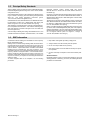
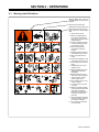
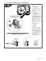
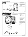
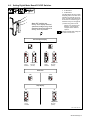
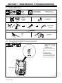
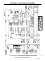
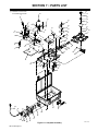
OM-215 092
210 177A
August 2005
Processes
MIG (GMAW) Welding
Flux Cored (FCAW) Welding
Description
Wire Feeder
UWF-SC12RC
TABLE OF CONTENTS
SECTION 1 − SAFETY PRECAUTIONS - READ BEFORE USING . . . . . . . . . . . . . . . . . . . . . . . . . . . . . . . . . . .
1-1. Symbol Usage . . . . . . . . . . . . . . . . . . . . . . . . . . . . . . . . . . . . . . . . . . . . . . . . . . . . . . . . . . . . . . . . . . . . . . . .
1-2. Arc Welding Hazards . . . . . . . . . . . . . . . . . . . . . . . . . . . . . . . . . . . . . . . . . . . . . . . . . . . . . . . . . . . . . . . . . .
1-3. Additional Symbols For Installation, Operation, And Maintenance . . . . . . . . . . . . . . . . . . . . . . . . . . . . .
1-4. California Proposition 65 Warnings . . . . . . . . . . . . . . . . . . . . . . . . . . . . . . . . . . . . . . . . . . . . . . . . . . . . . . .
1-5. Principal Safety Standards . . . . . . . . . . . . . . . . . . . . . . . . . . . . . . . . . . . . . . . . . . . . . . . . . . . . . . . . . . . . .
1-6. EMF Information . . . . . . . . . . . . . . . . . . . . . . . . . . . . . . . . . . . . . . . . . . . . . . . . . . . . . . . . . . . . . . . . . . . . . .
SECTION 2 − DEFINITIONS . . . . . . . . . . . . . . . . . . . . . . . . . . . . . . . . . . . . . . . . . . . . . . . . . . . . . . . . . . . . . . . . . . .
2-1. Warning Label Definitions . . . . . . . . . . . . . . . . . . . . . . . . . . . . . . . . . . . . . . . . . . . . . . . . . . . . . . . . . . . . . .
2-2. Manufacturer’s Rating Label For CE Products . . . . . . . . . . . . . . . . . . . . . . . . . . . . . . . . . . . . . . . . . . . . .
2-3. Symbols And Definitions . . . . . . . . . . . . . . . . . . . . . . . . . . . . . . . . . . . . . . . . . . . . . . . . . . . . . . . . . . . . . . .
SECTION 3 − INSTALLATION . . . . . . . . . . . . . . . . . . . . . . . . . . . . . . . . . . . . . . . . . . . . . . . . . . . . . . . . . . . . . . . . . .
3-1. Specifications . . . . . . . . . . . . . . . . . . . . . . . . . . . . . . . . . . . . . . . . . . . . . . . . . . . . . . . . . . . . . . . . . . . . . . . .
3-2. 14-Pin Plug Information . . . . . . . . . . . . . . . . . . . . . . . . . . . . . . . . . . . . . . . . . . . . . . . . . . . . . . . . . . . . . . . .
3-3. Equipment Connection Diagram . . . . . . . . . . . . . . . . . . . . . . . . . . . . . . . . . . . . . . . . . . . . . . . . . . . . . . . . .
3-4. Gun Recommendation Table . . . . . . . . . . . . . . . . . . . . . . . . . . . . . . . . . . . . . . . . . . . . . . . . . . . . . . . . . . . .
3-5. Consumable Parts and Spares for the T-400 MP Torch . . . . . . . . . . . . . . . . . . . . . . . . . . . . . . . . . . . . . .
3-6. Installing And Aligning Wire Guide And Drive Rolls . . . . . . . . . . . . . . . . . . . . . . . . . . . . . . . . . . . . . . . . .
3-7. Connecting Welding Gun . . . . . . . . . . . . . . . . . . . . . . . . . . . . . . . . . . . . . . . . . . . . . . . . . . . . . . . . . . . . . . .
3-8. Connecting Shielding Gas . . . . . . . . . . . . . . . . . . . . . . . . . . . . . . . . . . . . . . . . . . . . . . . . . . . . . . . . . . . . . .
3-9. Connecting Weld Cable . . . . . . . . . . . . . . . . . . . . . . . . . . . . . . . . . . . . . . . . . . . . . . . . . . . . . . . . . . . . . . . .
3-10. Installing And Threading Welding Wire . . . . . . . . . . . . . . . . . . . . . . . . . . . . . . . . . . . . . . . . . . . . . . . . . . . .
SECTION 4 − OPERATION . . . . . . . . . . . . . . . . . . . . . . . . . . . . . . . . . . . . . . . . . . . . . . . . . . . . . . . . . . . . . . . . . . . .
4-1. Controls . . . . . . . . . . . . . . . . . . . . . . . . . . . . . . . . . . . . . . . . . . . . . . . . . . . . . . . . . . . . . . . . . . . . . . . . . . . . .
4-2. Setting Digital Meter Board PC4 DIP Switches . . . . . . . . . . . . . . . . . . . . . . . . . . . . . . . . . . . . . . . . . . . . .
SECTION 5 − MAINTENANCE & TROUBLESHOOTING . . . . . . . . . . . . . . . . . . . . . . . . . . . . . . . . . . . . . . . . . . .
5-1. Routine Maintenance . . . . . . . . . . . . . . . . . . . . . . . . . . . . . . . . . . . . . . . . . . . . . . . . . . . . . . . . . . . . . . . . . .
5-2. Overload Protection And Thermostat Protection . . . . . . . . . . . . . . . . . . . . . . . . . . . . . . . . . . . . . . . . . . . .
5-3. Troubleshooting . . . . . . . . . . . . . . . . . . . . . . . . . . . . . . . . . . . . . . . . . . . . . . . . . . . . . . . . . . . . . . . . . . . . . .
SECTION 6 − ELECTRICAL DIAGRAMS . . . . . . . . . . . . . . . . . . . . . . . . . . . . . . . . . . . . . . . . . . . . . . . . . . . . . . . .
SECTION 7− PARTS LIST . . . . . . . . . . . . . . . . . . . . . . . . . . . . . . . . . . . . . . . . . . . . . . . . . . . . . . . . . . . . . . . . . . . . .
WARRANTY
1
1
1
3
3
4
4
5
5
6
6
6
6
7
7
8
8
9
10
10
11
11
12
12
13
14
14
14
15
17
18
Declaration of Conformity for
European Community (CE) Products
NOTE
This information is provided for units with CE certification (see rating label on unit).
Manufacturer:
European Contact:
Miller Electric Mg. Co.
1635 W. Spencer St.
Appleton, WI 54914 USA
Phone: (920) 734-9821
Mr. Danilo Fedolfi,
Managing Director
ITW Welding Products Italy S.r.l.
Via Privata Iseo 6/E
20098 San Giuliano
Milanese, Italy
Phone: 39(02)98290-1
Fax: 39(02)98290203
European Contact Signature:
Declares that the product:
UWF-SC12RC
conforms to the following Directives and Standards:
Directives
Low Voltage Directive: 73/23/EEC
Electromagnetic Compatibility (EMC) Directive: 89/336/EEC
Machinery Directives: 98/37/EEC, 91/368/EEC, 92/31/EEC, 133/04, 93/68/EEC
Standards
Arc Welding Equipment − Part 5: Wire Feeders. IEC 60974-5 Ed. 1
Arc Welding Equipment − Part 10: Electromagnetic Compatibility (EMC) Requirements. IEC 60974-10 August 2002
Arc Welding Equipment − Part 1: Welding Power Sources. IEC 60974-1 Ed. 2.1
Degrees Of Protection Provided By Enclosure (IP Code) IEC 60529 Ed. 2.1
Insulation Coordination For Equipment Within Low-Voltage Systems −
Part 1: Principles, Requirements and Tests: IEC 60664-1 Ed. 1.1
The product technical file is maintained by the responsible Business Unit(s) located at the manufacturing facility.
dec_wire_6/05
SECTION 1 − SAFETY PRECAUTIONS - READ BEFORE USING
som _3/05
Y Warning: Protect yourself and others from injury — read and follow these precautions.
1-1. Symbol Usage
Means Warning! Watch Out! There are possible hazards
with this procedure! The possible hazards are shown in
the adjoining symbols.
Y Marks a special safety message.
. Means “Note”; not safety related.
This group of symbols means Warning! Watch Out! possible
ELECTRIC SHOCK, MOVING PARTS, and HOT PARTS hazards.
Consult symbols and related instructions below for necessary actions
to avoid the hazards.
1-2. Arc Welding Hazards
Y The symbols shown below are used throughout this manual to
call attention to and identify possible hazards. When you see
the symbol, watch out, and follow the related instructions to
avoid the hazard. The safety information given below is only
a summary of the more complete safety information found in
the Safety Standards listed in Section 1-5. Read and follow all
Safety Standards.
Y Only qualified persons should install, operate, maintain, and
repair this unit.
D
D
D
D
D
D
Y During operation, keep everybody, especially children, away.
ELECTRIC SHOCK can kill.
Touching live electrical parts can cause fatal shocks
or severe burns. The electrode and work circuit is
electrically live whenever the output is on. The input
power circuit and machine internal circuits are also
live when power is on. In semiautomatic or automatic wire welding, the
wire, wire reel, drive roll housing, and all metal parts touching the
welding wire are electrically live. Incorrectly installed or improperly
grounded equipment is a hazard.
D Do not touch live electrical parts.
D Wear dry, hole-free insulating gloves and body protection.
D Insulate yourself from work and ground using dry insulating mats
or covers big enough to prevent any physical contact with the work
or ground.
D Do not use AC output in damp areas, if movement is confined, or if
there is a danger of falling.
D Use AC output ONLY if required for the welding process.
D If AC output is required, use remote output control if present on
unit.
D Additional safety precautions are required when any of the following electrically hazardous conditions are present: in damp
locations or while wearing wet clothing; on metal structures such
as floors, gratings, or scaffolds; when in cramped positions such
as sitting, kneeling, or lying; or when there is a high risk of unavoidable or accidental contact with the workpiece or ground. For these
conditions, use the following equipment in order presented: 1) a
semiautomatic DC constant voltage (wire) welder, 2) a DC manual
(stick) welder, or 3) an AC welder with reduced open-circuit voltage. In most situations, use of a DC, constant voltage wire welder
is recommended. And, do not work alone!
D Disconnect input power or stop engine before installing or
servicing this equipment. Lockout/tagout input power according to
OSHA 29 CFR 1910.147 (see Safety Standards).
D Properly install and ground this equipment according to its
Owner’s Manual and national, state, and local codes.
D Always verify the supply ground − check and be sure that input
power cord ground wire is properly connected to ground terminal in
disconnect box or that cord plug is connected to a properly
grounded receptacle outlet.
D When making input connections, attach proper grounding conductor first − double-check connections.
D Frequently inspect input power cord for damage or bare wiring −
replace cord immediately if damaged − bare wiring can kill.
D
D
D
D
D
D
Turn off all equipment when not in use.
Do not use worn, damaged, undersized, or poorly spliced cables.
Do not drape cables over your body.
If earth grounding of the workpiece is required, ground it directly
with a separate cable.
Do not touch electrode if you are in contact with the work, ground,
or another electrode from a different machine.
Do not touch electrode holders connected to two welding machines at the same time since double open-circuit voltage will be
present.
Use only well-maintained equipment. Repair or replace damaged
parts at once. Maintain unit according to manual.
Wear a safety harness if working above floor level.
Keep all panels and covers securely in place.
Clamp work cable with good metal-to-metal contact to workpiece
or worktable as near the weld as practical.
Insulate work clamp when not connected to workpiece to prevent
contact with any metal object.
Do not connect more than one electrode or work cable to any
single weld output terminal.
SIGNIFICANT DC VOLTAGE exists in inverter-type
welding power sources after removal of input
power.
D Turn Off inverter, disconnect input power, and discharge input
capacitors according to instructions in Maintenance Section
before touching any parts.
FUMES AND GASES can be hazardous.
Welding produces fumes and gases. Breathing
these fumes and gases can be hazardous to your
health.
D Keep your head out of the fumes. Do not breathe the fumes.
D If inside, ventilate the area and/or use local forced ventilation at the
arc to remove welding fumes and gases.
D If ventilation is poor, wear an approved air-supplied respirator.
D Read and understand the Material Safety Data Sheets (MSDSs)
and the manufacturer’s instructions for metals, consumables,
coatings, cleaners, and degreasers.
D Work in a confined space only if it is well ventilated, or while
wearing an air-supplied respirator. Always have a trained watchperson nearby. Welding fumes and gases can displace air and
lower the oxygen level causing injury or death. Be sure the breathing air is safe.
D Do not weld in locations near degreasing, cleaning, or spraying operations. The heat and rays of the arc can react with vapors to form
highly toxic and irritating gases.
D Do not weld on coated metals, such as galvanized, lead, or
cadmium plated steel, unless the coating is removed from the weld
area, the area is well ventilated, and while wearing an air-supplied
respirator. The coatings and any metals containing these elements
can give off toxic fumes if welded.
OM-215 092 Page 1
ARC RAYS can burn eyes and skin.
Arc rays from the welding process produce intense
visible and invisible (ultraviolet and infrared) rays
that can burn eyes and skin. Sparks fly off from the
weld.
D Wear an approved welding helmet fitted with a proper shade of filter lenses to protect your face and eyes when welding or watching
(see ANSI Z49.1 and Z87.1 listed in Safety Standards).
D Wear approved safety glasses with side shields under your
helmet.
D Use protective screens or barriers to protect others from flash,
glare and sparks; warn others not to watch the arc.
D Wear protective clothing made from durable, flame-resistant material (leather, heavy cotton, or wool) and foot protection.
WELDING can cause fire or explosion.
Welding on closed containers, such as tanks,
drums, or pipes, can cause them to blow up. Sparks
can fly off from the welding arc. The flying sparks, hot
workpiece, and hot equipment can cause fires and
burns. Accidental contact of electrode to metal objects can cause
sparks, explosion, overheating, or fire. Check and be sure the area is
safe before doing any welding.
D Remove all flammables within 35 ft (10.7 m) of the welding arc. If
this is not possible, tightly cover them with approved covers.
D Do not weld where flying sparks can strike flammable material.
D Protect yourself and others from flying sparks and hot metal.
D Be alert that welding sparks and hot materials from welding can
easily go through small cracks and openings to adjacent areas.
D Watch for fire, and keep a fire extinguisher nearby.
D Be aware that welding on a ceiling, floor, bulkhead, or partition can
cause fire on the hidden side.
D Do not weld on closed containers such as tanks, drums, or pipes,
unless they are properly prepared according to AWS F4.1 (see
Safety Standards).
D Connect work cable to the work as close to the welding area as
practical to prevent welding current from traveling long, possibly
unknown paths and causing electric shock, sparks, and fire
hazards.
D Do not use welder to thaw frozen pipes.
D Remove stick electrode from holder or cut off welding wire at
contact tip when not in use.
D Wear oil-free protective garments such as leather gloves, heavy
shirt, cuffless trousers, high shoes, and a cap.
D Remove any combustibles, such as a butane lighter or matches,
from your person before doing any welding.
D Follow requirements in OSHA 1910.252 (a) (2) (iv) and NFPA 51B
for hot work and have a fire watcher and extinguisher nearby.
FLYING METAL can injure eyes.
D Welding, chipping, wire brushing, and grinding
cause sparks and flying metal. As welds cool,
they can throw off slag.
D Wear approved safety glasses with side
shields even under your welding helmet.
OM-215 092 Page 2
BUILDUP OF GAS can injure or kill.
D Shut off shielding gas supply when not in use.
D Always ventilate confined spaces or use
approved air-supplied respirator.
HOT PARTS can cause severe burns.
D Do not touch hot parts bare handed.
D Allow cooling period before working on gun or
torch.
D To handle hot parts, use proper tools and/or
wear heavy, insulated welding gloves and
clothing to prevent burns.
MAGNETIC FIELDS can affect pacemakers.
D Pacemaker wearers keep away.
D Wearers should consult their doctor before
going near arc welding, gouging, or spot
welding operations.
NOISE can damage hearing.
Noise from some processes or equipment can
damage hearing.
D Wear approved ear protection if noise level is
high.
CYLINDERS can explode if damaged.
Shielding gas cylinders contain gas under high
pressure. If damaged, a cylinder can explode. Since
gas cylinders are normally part of the welding
process, be sure to treat them carefully.
D Protect compressed gas cylinders from excessive heat, mechanical shocks, physical damage, slag, open flames, sparks, and arcs.
D Install cylinders in an upright position by securing to a stationary
support or cylinder rack to prevent falling or tipping.
D Keep cylinders away from any welding or other electrical circuits.
D Never drape a welding torch over a gas cylinder.
D Never allow a welding electrode to touch any cylinder.
D Never weld on a pressurized cylinder − explosion will result.
D Use only correct shielding gas cylinders, regulators, hoses, and fittings designed for the specific application; maintain them and
associated parts in good condition.
D Turn face away from valve outlet when opening cylinder valve.
D Keep protective cap in place over valve except when cylinder is in
use or connected for use.
D Use the right equipment, correct procedures, and sufficient number of persons to lift and move cylinders.
D Read and follow instructions on compressed gas cylinders,
associated equipment, and Compressed Gas Association (CGA)
publication P-1 listed in Safety Standards.
1-3. Additional Symbols For Installation, Operation, And Maintenance
FIRE OR EXPLOSION hazard.
MOVING PARTS can cause injury.
D Do not install or place unit on, over, or near
combustible surfaces.
D Do not install unit near flammables.
D Do not overload building wiring − be sure power supply system is
properly sized, rated, and protected to handle this unit.
D Keep away from moving parts such as fans.
D Keep all doors, panels, covers, and guards
closed and securely in place.
D Have only qualified persons remove doors,
panels, covers, or guards for maintenance as
necessary.
D Reinstall doors, panels, covers, or guards
when maintenance is finished and before reconnecting input power.
FALLING UNIT can cause injury.
D Use lifting eye to lift unit only, NOT running
gear, gas cylinders, or any other accessories.
D Use equipment of adequate capacity to lift and
support unit.
D If using lift forks to move unit, be sure forks are
long enough to extend beyond opposite side of
unit.
READ INSTRUCTIONS.
D Read Owner’s Manual before using or servicing unit.
D Use only genuine Miller/Hobart replacement
parts.
H.F. RADIATION can cause interference.
OVERUSE can cause OVERHEATING
D Allow cooling period; follow rated duty cycle.
D Reduce current or reduce duty cycle before
starting to weld again.
D Do not block or filter airflow to unit.
D
D
STATIC (ESD) can damage PC boards.
D Put on grounded wrist strap BEFORE handling
boards or parts.
D Use proper static-proof bags and boxes to
store, move, or ship PC boards.
D
D
D High-frequency (H.F.) can interfere with radio
navigation, safety services, computers, and
communications equipment.
D Have only qualified persons familiar with
electronic equipment perform this installation.
The user is responsible for having a qualified electrician promptly correct any interference problem resulting from the installation.
If notified by the FCC about interference, stop using the
equipment at once.
Have the installation regularly checked and maintained.
Keep high-frequency source doors and panels tightly shut, keep
spark gaps at correct setting, and use grounding and shielding to
minimize the possibility of interference.
ARC WELDING can cause interference.
MOVING PARTS can cause injury.
D Keep away from moving parts.
D Keep away from pinch points such as drive
rolls.
D
WELDING WIRE can cause injury.
D Do not press gun trigger until instructed to do
so.
D Do not point gun toward any part of the body,
other people, or any metal when threading
welding wire.
D
D
D
D Electromagnetic energy can interfere with
sensitive electronic equipment such as
computers and computer-driven equipment
such as robots.
D Be sure all equipment in the welding area is
electromagnetically compatible.
To reduce possible interference, keep weld cables as short as
possible, close together, and down low, such as on the floor.
Locate welding operation 100 meters from any sensitive electronic equipment.
Be sure this welding machine is installed and grounded
according to this manual.
If interference still occurs, the user must take extra measures
such as moving the welding machine, using shielded cables,
using line filters, or shielding the work area.
1-4. California Proposition 65 Warnings
Y Welding or cutting equipment produces fumes or gases which
contain chemicals known to the State of California to cause
birth defects and, in some cases, cancer. (California Health &
Safety Code Section 25249.5 et seq.)
For Gasoline Engines:
Y Engine exhaust contains chemicals known to the State of
California to cause cancer, birth defects, or other reproductive
harm.
Y Battery posts, terminals and related accessories contain lead
and lead compounds, chemicals known to the State of
California to cause cancer and birth defects or other
reproductive harm. Wash hands after handling.
For Diesel Engines:
Y Diesel engine exhaust and some of its constituents are known
to the State of California to cause cancer, birth defects, and
other reproductive harm.
OM-215 092 Page 3
1-5. Principal Safety Standards
Safety in Welding, Cutting, and Allied Processes, ANSI Standard Z49.1,
from Global Engineering Documents (phone: 1-877-413-5184, website:
www.global.ihs.com).
Boulevard, Rexdale, Ontario, Canada M9W 1R3 (phone:
800−463−6727 or in Toronto 416−747−4044, website: www.csa−international.org).
Recommended Safe Practices for the Preparation for Welding and Cutting of Containers and Piping, American Welding Society Standard
AWS F4.1 from Global Engineering Documents (phone:
1-877-413-5184, website: www.global.ihs.com).
Practice For Occupational And Educational Eye And Face Protection,
ANSI Standard Z87.1, from American National Standards Institute, 11
West 42nd Street, New York, NY 10036−8002 (phone: 212−642−4900,
website: www.ansi.org).
National Electrical Code, NFPA Standard 70, from National Fire Protection Association, P.O. Box 9101, 1 Battery March Park, Quincy, MA
02269−9101 (phone: 617−770−3000, website: www.nfpa.org).
Standard for Fire Prevention During Welding, Cutting, and Other Hot
Work, NFPA Standard 51B, from National Fire Protection Association,
P.O. Box 9101, 1 Battery March Park, Quincy, MA 02269−9101 (phone:
617−770−3000,website: www.nfpa.org).
Safe Handling of Compressed Gases in Cylinders, CGA Pamphlet P-1,
from Compressed Gas Association, 1735 Jefferson Davis Highway,
Suite 1004, Arlington, VA 22202−4102 (phone: 703−412−0900, website: www.cganet.com).
Code for Safety in Welding and Cutting, CSA Standard W117.2, from
Canadian Standards Association, Standards Sales, 178 Rexdale
OSHA, Occupational Safety and Health Standards for General Industry, Title 29, Code of Federal Regulations (CFR), Part 1910, Subpart Q,
and Part 1926, Subpart J, from U.S. Government Printing Office, Superintendent of Documents, P.O. Box 371954, Pittsburgh, PA 15250 (there
are 10 Regional Offices−−phone for Region 5, Chicago, is
312−353−2220,website: www.osha.gov).
1-6. EMF Information
Considerations About Welding And The Effects Of Low Frequency
Electric And Magnetic Fields
Welding current, as it flows through welding cables, will cause electromagnetic fields. There has been and still is some concern about such
fields. However, after examining more than 500 studies spanning 17
years of research, a special blue ribbon committee of the National
Research Council concluded that: “The body of evidence, in the
committee’s judgment, has not demonstrated that exposure to powerfrequency electric and magnetic fields is a human-health hazard.”
However, studies are still going forth and evidence continues to be
examined. Until the final conclusions of the research are reached, you
may wish to minimize your exposure to electromagnetic fields when
welding or cutting.
To reduce magnetic fields in the workplace, use the following
procedures:
OM-215 092 Page 4
1. Keep cables close together by twisting or taping them.
2. Arrange cables to one side and away from the operator.
3. Do not coil or drape cables around your body.
4. Keep welding power source and cables as far away from operator as practical.
5. Connect work clamp to workpiece as close to the weld as possible.
About Pacemakers:
Pacemaker wearers consult your doctor before welding or going near
welding operations. If cleared by your doctor, then following the above
procedures is recommended.
SECTION 2 − DEFINITIONS
2-1. Warning Label Definitions
Warning! Watch Out! There are
possible hazards as shown by the
symbols.
Drive rolls can injure fingers
Welding wire and drive parts are at
welding voltage during operation −
keep hands and metal objects
clear.
1
1.1
2
2.1
3
3.1
4
4.1
1.2
2.2
2.3
3.2
+
5
1.3
3.3
+
+
6
+
S-178 936
1 Electric shock can kill.
1.1 Wear dry insulating gloves.
Do not touch electrode with
bare hand. Do not wear wet or
damaged gloves.
1.2 Protect yourself from electric
shock by insulating yourself
from work and ground.
1.3 Disconnect input plug or
power before working on
machine.
2 Breathing welding fumes can
be hazardous to your health.
2.1 Keep your head out of the
fumes.
2.2 Use forced ventilation or local
exhaust to remove the fumes.
2.3 Use ventilating fan to remove
fumes.
3 Welding sparks can cause
explosion or fire.
3.1 Keep flammables away from
welding. Don’t weld near
flammables.
3.2 Welding sparks can cause
fires. Have a fire extinguisher
nearby and have a watch
person ready to use it.
3.3 Do not weld on drums or any
closed containers.
4 Arc rays can burn eyes and
injure skin.
4.1 Wear hat and safety glasses.
Use ear protection and button
shirt collar. Use welding
helmet with correct shade of
filter. Wear complete body
protection.
5 Become trained and read the
instructions before working on
the machine or welding.
6 Do not remove or paint over
(cover) the label.
OM-215 092 Page 5
2-2. Manufacturer’s Rating Label For CE Products
For label location
see Section 4-1.
S/N:
U1 24 V
=I1= 10.0 A
50/60 Hz
IP 23
1
U2 100 V I2= 500 A
X 100 %
= MILLER ELECTRIC MFG. CO., APPLETON, WI USA
2-3. Symbols And Definitions
NOTE
X
Some symbols are found only on CE products.
Duty Cycle
Wire Feed
Percent
Input
Cold Jog (Inch) Towards Workpiece
Purge By Gas
Fast
Constant Current
Circuit Breaker
Constant Voltage
Slow
Trigger Hold Off
Trigger Hold On
Rated Welding
Current
Increase
U1
Primary Voltage
I2
U2
Amperes
V
IP
Input
Read Instructions
I1
A
Output
Conventional Load
Voltage
Volts
Degree Of Protection
Hz
Hertz
Primary Current
SECTION 3 − INSTALLATION
3-1. Specifications
Type of
Input
Power
Welding
Power
Source
Type
24 Volts AC
Single Phase
10 Amperes
50/60 Hz
Constant
Voltage (CV)
DC With
14-Pin And
Contactor
Control
OM-215 092 Page 6
Wire Feed
Speed
Range
50 to 700 ipm
(1.3 To 17.8
mpm)
Wire
Diameter
Range
Input
Welding
Circuit
Rating
.023 To 5/64 in
(0.6 To 2 mm)
100 Volts,
500
Amperes,
100%
Duty Cycle
IP
Rating
23
Max. Wire
Spool
Capacity
30 lb (13.6
kg),
12 in (304
mm)
Overall
Dimensions
Weight
Length: 20 in
(508 mm)
Width: 8 in
(203 mm)
Height: 15-1/2 in
(394 mm)
25.5 lb
(11.6 kg)
3-2. 14-Pin Plug Information
Pin*
J
I
H
K
A
B
L C
M D
E
N
G
F
Pin Information
A
24 volts ac with respect to socket G.
B
Contact closure to A completes 24 volts ac contactor control circuit.
G
Circuit common for 24 volts AC circuit.
C
+10 volts dc input from power source to wire feeder with respect to socket D.
D
Remote control circuit common.
E
0 to +10 volts dc output signal from wire feeder to power source with respect to socket D.
H
Voltage feedback; 0 to +10 volts dc, 1 volt per 10 arc volts.
F
Current feedback; 0 to +10 volts dc, 1 volt per 100 amperes.
*The remaining pins are not used.
3-3. Equipment Connection Diagram
1
Constant Voltage (CV)
Welding Power Source
Supplying 24 VAC To Feeder
Use optional PSA-2 adapter for
power sources having only 115
VAC supply.
1
2
3
4
5
Negative (−) Weld Cable
Positive (+) Weld Cable
Workpiece
Interconnecting Cord
(Customer Supplied)
6 14-Pin Plug And Cord
7 Wire Feeder
8 Gun
9 Gun Trigger Receptacle
10 Gas Hose
11 Gas Cylinder
11
2
. Shielding gas pressure not to
exceed 90 psi (620 kPa).
3
10
9
5
4
6
8
7
804 207-A
OM-215 092 Page 7
3-4. Gun Recommendation Table
Process
Gun
GMAW − Hard or Cored Wires
T-400 MP
FCAW − Self-Shielding Wires
T-400 MP + torch neck for self-sheilding wire
3-5. Consumable Parts and Spares for the T-400 MP Torch
The torch has adjustable neck and
is delivered complete with tools for
neck adjustment and contact tip
change. It is delivered with 3 m
cable, complete with liner and contact tips for 0.8–1.2 mm wire. The
teflon liner allows for all wire types
including aluminium.
A
1
2
10
9
8
6
7
B
5
A
3
B
4
Pos.
Unit
Product no.
1
Description
Wire torch for T-400 MP for gas shielded wire with 3 m cable and connector with 1.2 mm contact tip and steel liner (1.2 − 1.4 mm).
pcs
193-607451
2
Torch neck 160 mm for self-shileded wire. To be mounted on wire
torch T-400 MP handle.
pcs
193-607452
3
Torch neck 300 mm for self-shileded wire. To be mounted on wire
torch T-400 MP handle.
pcs
193-607453
4
Tip insulation cup for self-shileded neck.
pcs
193-607454
5
Gas nozzle for torch.
pcs
193-613765
6
Contact tips −
0.8 mm
1.0-1.2 mm
1.2-1.4 mm
1.6-2.0 mm
10
10
10
10
set
set
set
set
193-594622
193-594630
193-607455
193-607456
7
Nozzle insulator.
5
set
193-613766
8
Gas diffuser for T-400.
5
set
193-613763
9
Neck insualtor for T-400.
5
set
193-613764
10
Torch liner, Teflon for 0.8-1.2 mm wire 4.5 m long.
Torch liner, Steel for 0.8-1.2 mm wire (blue) 3.0 m long.
Torch liner, Steel for 3 m for 1.4-2.0 mm wire (red) 3.0 m long
pcs
pcs
pcs
193-594606
193-594614
193-607457
OM-215 092 Page 8
Qty.
3-6. Installing And Aligning Wire Guide And Drive Rolls
Installing Wire Guide And Drive
Rolls:
1
2
Drive Roll Nut
Drive Roll Carrier
Turn nut one click until lobes of nut
line up with lobes of drive roll carrier.
3
Drive Roll
Slide drive roll onto drive roll carrier.
Turn nut one click.
Repeat procedure for top drive roll.
4
5
Inlet Wire Guide Screw
Inlet Wire Guide
Loosen securing screw. Install inlet
guide so inlet guide screw is
centered in groove in guide, or so tip
is as close to drive rolls as possible
without touching. Tighten screw.
Installing Wire Guide
And Drive Rolls
Aligning Wire Guide And Drive
Rolls:
View is from top of drive rolls looking down with pressure assembly
open.
5
6
7
8
9
10
4
3
Drive Roll Securing Nut
Drive Roll
Wire Guide
Welding Wire
Drive Gear
Turn screw in or out until drive roll
groove lines up with wire guide.
1
Close pressure roll assembly.
Only bottom drive roll alignment is
adjustable. Turn adjustment screw
in or out until groove in drive roll
lines up with wire guide as shown.
2
Cleaning Drive Rolls:
Aligning Wire Guide And Drive Rolls
Correct
8
Remove drive rolls, and clean
grooves using a wire brush.
Incorrect
9
7
Tools Needed:
6
3/16 in
10
3/8 in
804 210-A
OM-215 092 Page 9
3-7. Connecting Welding Gun
1
2
3
Gun Securing Knob
Gun Block
Gun Outlet Wire Guide
Loosen knob, insert gun end into
block. Position outlet wire guide as
close as possible to drive rolls without touching. Tighten knob.
2
1
4
5
Gun Trigger Plug
Gun Trigger Receptacle
Internal Side View
3
4
5
804 209-A
3-8. Connecting Shielding Gas
1
2
Gas Hose With 5/8-18
Right-hand Thread Fittings
(Customer Supplied)
Shielding Gas Cylinder
. Shielding gas pressure not to
exceed 90 psi (620 kPa).
Rear View
3
4
3
4
5
Valve
Flowmeter
14-Pin Plug
Close valve on cylinder when finished welding.
2
5
Tools Needed:
5/8 in
OM-215 092 Page 10
1
804 208-A
3-9. Connecting Weld Cable
1
User-Suppled Weld Cable
Follow wire manufacturer’s recommendations for weld cable polarity.
2
3
From Wire Feeder
User-Suppled Male Connector
User-Suppled Female
Connector
Push female connector over male
connector, and turn 1/4 turn clockwise.
2
1
3
804 211-A
3-10. Installing And Threading Welding Wire
Hold wire tightly to keep it
from unraveling.
Installing Wire And Adjusting
Hub Tension:
1
2
Retaining Nut
Hub Tension Adjustment
Screw
Remove retaining ring, and install
spool so hub pin fits spool hole. Reinstall retaining nut.
Adjust tension nut so only a slight
force is needed to turn spool.
Threading Welding Wire:
3
Pressure Assembly
Adjustment Knob
Lay gun cable out straight.
Open pressure assembly, hold wire
tightly, and cut off end. Push wire
through guides into gun.
3
1
2
Close and tighten pressure assembly. Press Jog switch until wire
comes out gun.
Feed wire against wooden surface,
and tighten knob so wire does not
slip.
Cut off wire, and close door.
6 in
(150 mm)
Pull and hold wire; cut off end.
Tighten
Clockwise
Tools Needed:
9/16 in
WOOD
804 212-A
OM-215 092 Page 11
SECTION 4 − OPERATION
4-1. Controls
1
2
Depress the upper part of the switch
(turns trigger hold On) to weld without
holding gun trigger throughout the
weld cycle.
2
OFF
3
1
To start weld, press and release gun
trigger. To end weld, press and release gun trigger.
ON
PURGE
Power Control Switch
Trigger Hold Switch (Optional)
Depress the lower part of the trigger
hold switch to turn trigger hold Off.
POWER
3
4
Purge Switch
Press switch to momentarily energize
gas solenoid and purge air from gun,
and to adjust shielding gas regulator.
4
5
5
7
6
. Meter
is factory set to display
voltage and wirefeed speed. To
display voltage and amps refer to
Section 4-2 for DIP switch settings.
6
7
VOLTAGE
WIRE SPEED
Voltage Control
Wire Speed Control
Use control to adjust wire speed within range selected by switch.
8
Front Panel
Meter Display (Optional)
Volts, Wire Feed Speed Or
Amps Select Switch (Optional)
Jog Switch
Use Jog position to momentarily feed
welding wire at speed set on Wire
Speed control without energizing
welding circuit or shielding gas valve.
Close and latch door.
8
JOG
Internal Control Panel
Internal Side View
804 213-A
OM-215 092 Page 12
4-2. Setting Digital Meter Board PC4 DIP Switches
1
2
3
Front Meter Panel
S1 DIP Switch
S2 DIP Switch
If the DIP switches are set to a Meter
Hold (ON) position, the meter value
will hold 5 seconds after gun is triggered. The meter value will continue
to hold for 8 seconds after trigger is
released or until gun is re-triggered.
1
2
3
. When using power sources
Meter DIP switches are
factory set to display wirefeed
speed and voltage using 14 pin
feedback. Meter hold feature is
factory set to off position.
without 14 pin voltage/current
feedback − optional remote
voltage/current kit 195194 is
required.
Indicates this DIP switch setting has
no effect on this function.
Wire Feed Speed Display
Inches Per Minute
Meters Per Minute
S1
S1
S2
S2
S2
S2
14 Pin
Voltage
Feedback
Voltage/Current
Sense Kit
(195194)
14 Pin
Voltage
Feedback
Voltage/Current
Sense Kit
(195194)
Meter Hold
(ON)
(OFF)
S1
S1
Amps Display
S2
14 Pin
Current
Feedback
S2
Voltage/Current
Sense Kit
(195194)
803 141/ Ref. 803 124
OM-215 092 Page 13
SECTION 5 − MAINTENANCE & TROUBLESHOOTING
5-1. Routine Maintenance
. Maintain more often
Y Disconnect power
before maintaining.
during severe conditions.
3 Months
Replace
Damaged Or
Unreadable
Labels
Replace Damaged
Gas Hose
Repair Or Replace
Cracked Cables
And Cords
6 Months
Clean
Drive
Rolls
Blow Out Or
Vacuum Inside
5-2. Overload Protection And Thermostat Protection
Y Turn Off wire feeder and
welding power source. Stop
engine
on
welding
generator.
1
1
Circuit Breaker CB1
CB1 protects wire feeder from overload. Correct problem and reset
CB1.
Close and latch door.
CB1
Thermostat Protection
Unit has internal thermostat protection and will not feed wire if overheating occurs (see Section 5-3).
Internal Side View
804 213-A
OM-215 092 Page 14
5-3. Troubleshooting
Trouble
Remedy
Wire does not feed, unit completely inop- Turn Power switch On.
erative.
Check 14−pin plug PLG2 connections.
Check input power.
Wire does not feed.
Check circuit breaker CB1. (see Section 5-2).
Check gun trigger connection at wire feeder. Check gun trigger leads and trigger switch. See gun Owner’s
Manual.
Have Factory Authorized Service Agent check drive motor and control board PC1.
Wire feeds erratically.
Readjust hub tension and drive roll pressure (see Section 3-10).
Use correct size drive roll (see Parts Listing).
Clean or replace dirty or worn drive roll (see Section 3-6).
Remove weld spatter around nozzle opening.
Replace contact tip or liner. See gun Owner’s Manual.
Have Factory Authorized Service Agent check drive motor and control board PC1.
Wire feeds when Jog switch is pressed Check gun trigger connection at wire feeder. Check gun trigger leads and trigger switch. See gun Owner’s
but not when gun trigger is pressed.
Manual.
Wire feeds as soon as power is applied. Check gun trigger. See gun Owner’s Manual.
Wire does not feed until trigger is Check for short between gun trigger leads and weld cable. Repair or replace gun trigger leads.
pressed but continues to feed after trigger is released.
Gas valve rattles loudly and wire feeds Check for short between gun trigger leads and weld cable. Repair or replace gun trigger leads.
slowly or erratically.
Gas does not flow; wire feeds.
Check gas valve.
OM-215 092 Page 15
Notes
OM-215 092 Page 16
SECTION 6 − ELECTRICAL DIAGRAMS
223 794-B
Figure 6-1. Circuit Diagram For Wire Feeder
OM-215 092 Page 17
SECTION 7 − PARTS LIST
. Hardware is common and
32
not available unless listed.
22
33
3
34
21
35
27
4
36
5
6
19
28
7
35
29
20
38
18
2
37
23
30
17
16
1
25
24
15
31
14
42
13
11 47
8
69
26
12
70
41
9
9
43
45
44
39
46
40
52
10
53
54
48
49
55
50
56
51
68
58
67
57
59
60
61
66
65 64
OM-215 092 Page 18
62
63
Figure 8-1. Complete Assembly
804 214-D
Item
No.
Dia.
Mkgs.
Part
No.
Description
Quantity
Figure 7-1. Complete Assembly
. . 1 . . . . M1 . . . ME220 195
. . 2 . . . . . . . . . . . ME207 679
. . 3 . . . . . . . . . . . ME124 778
. . 4 . . . . . . . . . . . ME172 076
. . 5 . . . . . . . . . . . ME092 865
. . 6 . . . . . . . . . . . ME079 625
. . 7 . . . . . . . . . . . ME010 224
. . 8 . . . . . . . . . . . ME144 172
. . 9 . . . . . . . . . . . ME098 615
. . 10 . . . . . . . . . . ME225 306
. . 11 . . . . . . . . . . ME151 828
. . 12 . . . . . . . . . . ME079 634
. . 13 . . . . . . . . . . ME166 071
. . 14 . . . . . . . . . . ME085 243
. . 15 . . . . . . . . . . ME085 244
. . 16 . . . . . . . . . . ME089 562
. . 17 . . . . . . . . . . ME172 075
. . 18 . . . . . . . . . . ME220 221
. . 19 . . . . . . . . . . ME225 934
. . 20 . . . . . . . . . . ME026 947
. . 21 . . . . . . . . . . ME600 324
. . 22 . . . . . . . . . . ME221 347
. . 23 . . PC30 . ♦ME211 444
. . 24 . . . . . . . . . ♦ME097 132
. . 25 . . PC1 . . ME218 488
. . 26 . . . . . . . . . . ME097 132
. . 27 . . . . . . . . . . ME210 133
. . 28 . . . C1 . . . ME177 360
. . 29 . . . . . . . . . . ME207 678
. . 30 . . . . . . . . . . . ME211 989
. . 31 . . . . . . . . . . ME220 805
. . 32 . . . . . . . . . . ME209 450
. . 33 . . . . . . . . . . ME172 919
. . 34 . . . . . . . . . . ME172 918
. . 35 . . . . . . . . . . ME201 309
. . 36 . . . . . . . . . . ME225 069
. . 37 . . . . . . . . . . ME058 424
. . 38 . . . . . . . . . . ME221 052
. . 39 . . . . . . . . . . ME222 294
. . 40 . . . . . . . . . . ME222 103
. . 41 . . . . . . . . . . ME210 364
. . . . . . . . . . . . . . . . ME079 739
. . . . . . . . . . . . . . . . ME600 797
. . . . . . . . PLG9 . . ME141 162
. . . . . . . PLG21 . . ME115 093
. . . . . . . PLG41 . ME131 204
. . 42 . . . . . . . . . . ME139 041
. . 43 . . . . . . . . . . ME215 980
. . 44 . . . . . . . . . . ME214 860
. . 45 . . . . . . . . . . ME222 067
. . 46 . . . . . . . . . . ME182 445
. . 47 . . GS1 . . ME216 126
. . 48 . . . . . . . . . . ME222 181
. . 49 . . . . . . . . . . ME221 051
. . 50 . . . . . . . . . . ME208 000
. . Motor, Right Angle 24VDC 145 Rpm 37.5 Ratio W/Plug . . . . . . . . . . . . . . 1
. . Insert, Corner . . . . . . . . . . . . . . . . . . . . . . . . . . . . . . . . . . . . . . . . . . . . . . . . . . . 1
. . Knob, T 2.000 Bar W/.312−18 Stud 1.000 Lg Plstc . . . . . . . . . . . . . . . . . . . 1
. . Carrier, Drive Roll W/Components Keyed 24 Pitch . . . . . . . . . . . . . . . . . . . 1
. . Key, Stl .1215/.1230 x .750 . . . . . . . . . . . . . . . . . . . . . . . . . . . . . . . . . . . . . . . 1
. . Washer, Wave .500idx0.750odx.015t Stl Lbs . . . . . . . . . . . . . . . . . . . . . . . . 2
. . Pin, Spring Cs .187 X 1.000 . . . . . . . . . . . . . . . . . . . . . . . . . . . . . . . . . . . . . . 1
. . Ftg, Hose Brs Barbed M 3/16 Tbg X .250−20 . . . . . . . . . . . . . . . . . . . . . . . . 1
. . Hose, Sae .187 Id X .410 Od X 20.000 . . . . . . . . . . . . . . . . . . . . . . . . . . . . . 1
. . Insulator, Motor . . . . . . . . . . . . . . . . . . . . . . . . . . . . . . . . . . . . . . . . . . . . . . . . . 1
. . Pin, Cotter Hair .042 X .750 . . . . . . . . . . . . . . . . . . . . . . . . . . . . . . . . . . . . . . . 2
. . Pin, Hinge . . . . . . . . . . . . . . . . . . . . . . . . . . . . . . . . . . . . . . . . . . . . . . . . . . . . . . 1
. . Lever, Mtg Pressure Gear . . . . . . . . . . . . . . . . . . . . . . . . . . . . . . . . . . . . . . . . 1
. . Knob, Adjust Tension 1.250 Dia X .312−18 Thrd Stl . . . . . . . . . . . . . . . . . . 1
. . Washer, Cupped .328IDX .812ODX16GAX.125 Lip . . . . . . . . . . . . . . . . . . 1
. . Fastener, Pinned . . . . . . . . . . . . . . . . . . . . . . . . . . . . . . . . . . . . . . . . . . . . . . . . 1
. . Carrier, Drive Roll W/Components 24 Pitch . . . . . . . . . . . . . . . . . . . . . . . . . 1
. . Thermostat, NC Open 140C Close 110C Snap Action . . . . . . . . . . . . . . . . 1
. . Bus Bar, Interconnecting . . . . . . . . . . . . . . . . . . . . . . . . . . . . . . . . . . . . . . . . . 1
. . Stand−Off, Insul .250−20 X 1.000 Lg X .312 Thd . . . . . . . . . . . . . . . . . . . . 1
. . Cable, Weld Cop Strd No 4/0 Epdm Jkt . . . . . . . . . . . . . . . . . . . . . . . . . . As Rqd
. . Grommet, Bus Bar . . . . . . . . . . . . . . . . . . . . . . . . . . . . . . . . . . . . . . . . . . . . . . 1
. . Circuit Card Assy Trigger Hold/Burnback (Meter Option) . . . . . . . . . . . . . . 1
. . Stand-Off, No 6-32 X .375 Lg (Meter Option) . . . . . . . . . . . . . . . . . . . . . . . . 4
. . Circuit Card Assy, Motor Speed Control . . . . . . . . . . . . . . . . . . . . . . . . . . . . 1
. . Stand-Off, No 6-32 X .375 Lg . . . . . . . . . . . . . . . . . . . . . . . . . . . . . . . . . . . . . 4
. . Bracket, Capacitor Support SC12 . . . . . . . . . . . . . . . . . . . . . . . . . . . . . . . . . . 1
. . Capacitor, Elctlt 20000 Uf 45 VDC Can 1.40 Dia . . . . . . . . . . . . . . . . . . . . . 1
. . Insulator, Capacitor . . . . . . . . . . . . . . . . . . . . . . . . . . . . . . . . . . . . . . . . . . . . . . 1
. . Fitting, W/Screen . . . . . . . . . . . . . . . . . . . . . . . . . . . . . . . . . . . . . . . . . . . . . . . . 1
. . Nut, 750-14 Knurled1.48hex .41h Nyl . . . . . . . . . . . . . . . . . . . . . . . . . . . . . . 1
. . Nut, Hub . . . . . . . . . . . . . . . . . . . . . . . . . . . . . . . . . . . . . . . . . . . . . . . . . . . . . . . 1
. . Knob, Brake Adjust . . . . . . . . . . . . . . . . . . . . . . . . . . . . . . . . . . . . . . . . . . . . . . 1
. . Spring . . . . . . . . . . . . . . . . . . . . . . . . . . . . . . . . . . . . . . . . . . . . . . . . . . . . . . . . . 1
. . Washer, Anti−turn . . . . . . . . . . . . . . . . . . . . . . . . . . . . . . . . . . . . . . . . . . . . . . . 2
. . Hub, Spool W/Threads . . . . . . . . . . . . . . . . . . . . . . . . . . . . . . . . . . . . . . . . . . . 1
. . Washer, Fibre (Brake) . . . . . . . . . . . . . . . . . . . . . . . . . . . . . . . . . . . . . . . . . . . . 1
. . Shroud, Wire . . . . . . . . . . . . . . . . . . . . . . . . . . . . . . . . . . . . . . . . . . . . . . . . . . . 1
. . Clip, Wire/Cord .380 Bundle .250Hole .105 Thk Blk . . . . . . . . . . . . . . . . . . 1
. . Support, Spool . . . . . . . . . . . . . . . . . . . . . . . . . . . . . . . . . . . . . . . . . . . . . . . . . . 1
. . Cable, Power 17 In (Includes) . . . . . . . . . . . . . . . . . . . . . . . . . . . . . . . . . . . . . 1
. . . . Conn, Circ Cpc Clamp Str Rlf Size 17−20 .703od . . . . . . . . . . . . . . . . . . 1
. . . . Cable, Port No 16 8/C Type So Rb Jkt . . . . . . . . . . . . . . . . . . . . . . . . . . . 1.4 ft
. . . . Housing Plug+Pins, (Service Kit) . . . . . . . . . . . . . . . . . . . . . . . . . . . . . . As Rqd
. . . . Housing Plug+Skts, (Service Kit) . . . . . . . . . . . . . . . . . . . . . . . . . . . . . . As Rqd
. . . . Housing Plug+Skts, (Service Kit) . . . . . . . . . . . . . . . . . . . . . . . . . . . . . . As Rqd
. . Bushing, Strain Relief .481/.617 Id X1.115 Mtg Hole . . . . . . . . . . . . . . . . . . 1
. . Bushing, Strain Relief .709/.984 Id X1.375 Mtg Hole . . . . . . . . . . . . . . . . . 1
. . Nut, Ln Pg21 1.26Hex .14H Nickel Plated Brass . . . . . . . . . . . . . . . . . . . . . 1
. . Insulator, Rear Panel . . . . . . . . . . . . . . . . . . . . . . . . . . . . . . . . . . . . . . . . . . . . 1
. . Nut, Conduit 1.000 Npt Pld 1.688 Od X .200 Thk . . . . . . . . . . . . . . . . . . . . 1
. . Valve, Gas W/Fittings 24VAC . . . . . . . . . . . . . . . . . . . . . . . . . . . . . . . . . . . . . 1
. . Grommet, Scr No 8/10 Panel Hole .281 Sq .031 High . . . . . . . . . . . . . . . . 5
. . Chassis, Control Box . . . . . . . . . . . . . . . . . . . . . . . . . . . . . . . . . . . . . . . . . . . . 1
. . Washer, Shldr.260 Id 0.630 Od X.125T .327Od X .062T Nyl . . . . . . . . . . . 4
OM-215 092 Page 19
Item
No.
Dia.
Mkgs.
Part
No.
Description
Quantity
Figure 7-1. Complete Assembly (Continued)
. . 51 . . . . . . . . . . ME081 895
. . 52 . . . . . . . . . . ME147 195
. . 53 . . . S3 . . . ME200 640
. . 54 . . . . . . . . . . ME210 141
. . 55 . . . . . . . . . . ME208 076
. . 56 . . CB1 . . ME083 432
. . 57 . . . . . . . . . . ME208 015
. . 58 . . . . . . . . . . ME221 050
. . 59 . . PC4 . ♦2ME10 768
. . 60 . R1, R50 . ME073 562
. . 61 . . . . . . . . . . ME225 312
. . 62 . . . . . . . . . . ME225 313
. . 62 . . . . . . . . . ♦ME225 370
. . 63 . . . S1 . . . . ME111 997
. . 64 . . S31 . . ♦ME120 376
. . 65 . . . S2 . . . ME200 640
. . 66 . . . . . . . . . . ME193 920
. . 66 . . . . . . . . . ♦ME093 551
. . 67 . . . . . . . . . . ME070 654
. . 68 . . . . . . . . . . ME221 998
. . 69 . . . . . . . . . . ME107 983
. . 70 . . . . . . . . . . ME222 159
. . . . . . . . . . . . . . . . ME049 455
. . . . . . . . RC2 . . ME048 834
. . . . . . . . . . . . . . . . ME080 328
. . . . . . . . PLG6 . . . ME115 094
. . . . . . . . . . . . . . . . ME223 814
. . . . . . . . . . . . . . . . ME223 815
. . . . . . . . . . . . . . . . ME196 596
. . . . . . . . . . . . . . . ♦ME133 644
. . . . . . . . PLG1 . . . ME115 093
. . . . . . . . PLG3 . . . ME115 092
. . . . . . . . PLG4 . . . ME115 091
. . . . . . . . PLG7 . . ME131 056
. . . . . . . . PLG8 . ♦ME115 093
. . . . . . . PLG13 . ME131 054
. . . . . . . PLG15 ♦ME130 203
. . . . . . . PLG16 ♦ME131 055
. . . . . . . PLG17 ♦ME191 929
. . . . . . . PLG31 ♦ME153 501
. . . . . . . PLG32 ♦ME164 899
. . . . . . . PLG33 . ME131 054
. . . . . . . PLG34 ♦ME115 093
. . . . . . . PLG43 ♦ME131 204
. . . . . . . . RC6 . . . ME115 090
. . . . . . . . RC7 . . ME131 058
. . . . . RC8, RC21 ME131 059
. . . . . . . . RC13 . . ME135 635
. . . . . . . . RC42 . . ME131 203
. . Nut, 010−32 Rubber .75Dia .81l Insert In .38Hole . . . . . . . . . . . . . . . . . . . . 5
. . Nut, 375−27 .54Hex .25h Nyl Flange .62D . . . . . . . . . . . . . . . . . . . . . . . . . . 1
. . Switch, Rocker Dpdt 8A 125VAC On−None−(On) . . . . . . . . . . . . . . . . . . . . 1
. . Nameplate, Inner . . . . . . . . . . . . . . . . . . . . . . . . . . . . . . . . . . . . . . . . . . . . . . . . 1
. . Panel, Inner . . . . . . . . . . . . . . . . . . . . . . . . . . . . . . . . . . . . . . . . . . . . . . . . . . . . 1
. . Circuit Breaker, Man Reset 1P 10A 250VAC Frict . . . . . . . . . . . . . . . . . . . . 1
. . Handle, Rubberized Carrying . . . . . . . . . . . . . . . . . . . . . . . . . . . . . . . . . . . . . 1
. . Case, Control Feeder Plastic . . . . . . . . . . . . . . . . . . . . . . . . . . . . . . . . . . . . . . 1
. . Circuit Card Assy, Meter (Meter Option) . . . . . . . . . . . . . . . . . . . . . . . . . . . . 1
. . Pot, Cp Std Slot 1t 2. W 10k Linear . . . . . . . . . . . . . . . . . . . . . . . . . . . . . . . . 2
. . Panel, Front . . . . . . . . . . . . . . . . . . . . . . . . . . . . . . . . . . . . . . . . . . . . . . . . . . . . 1
. . Nameplate . . . . . . . . . . . . . . . . . . . . . . . . . . . . . . . . . . . . . . . . . . . . . . . . . . . . . 1
. . Nameplate, (Meter Option) . . . . . . . . . . . . . . . . . . . . . . . . . . . . . . . . . . . . . . . 1
. . Switch, Rocker Spst 10A 250VAC On−Off Visi Red Rock . . . . . . . . . . . . . 1
. . Switch, Rocker Spdt 4A 250VAC On−None−On Spade Ter . . . . . . . . . . . . 1
. . Switch, Rocker Dpdt 8A 125VAC On−None−On Black . . . . . . . . . . . . . . . . 1
. . Knob, Pointer .840 Dia X .250 Id W/One Set Screw . . . . . . . . . . . . . . . . . . 2
. . Knob, Pointer (Meter Option) . . . . . . . . . . . . . . . . . . . . . . . . . . . . . . . . . . . . . . 2
. . Bushing, Strain Relief .300 Id X .550 Mtg Hole . . . . . . . . . . . . . . . . . . . . . . 1
. . Cable, Trigger 25 In (Includes) . . . . . . . . . . . . . . . . . . . . . . . . . . . . . . . . . . . . 1
. . Blank, snap-in, nylon, .500 mounting hole, black . . . . . . . . . . . . . . . . . . . . . 1
. . Spring, torsion . . . . . . . . . . . . . . . . . . . . . . . . . . . . . . . . . . . . . . . . . . . . . . . . . . 1
. . . . Cable, Port No 18 2/C Type sjo nprn Jkt . . . . . . . . . . . . . . . . . . . . . . . . . 3 ft
. . . . Conn, Circ Cpc Clamp Str Rlf Size 11 .329OD . . . . . . . . . . . . . . . . . . . . . 1
. . . . Rcpt W/Skts, Free Hanging . . . . . . . . . . . . . . . . . . . . . . . . . . . . . . . . . . . . . 1
. . . . Housing Plug+Skts, (Service Kit) . . . . . . . . . . . . . . . . . . . . . . . . . . . . . . . . 1
. . Label, Warn Gen Precaution Suitcase . . . . . . . . . . . . . . . . . . . . . . . . . . . . . . 3
. . Label, Warn Gen Precaution Suitcase (CE) . . . . . . . . . . . . . . . . . . . . . . . . . 3
. . Label, Warning Electric Shock And Pinch Wordless . . . . . . . . . . . . . . . . . . 1
. . Frame, Snap-In Switch Rocker Panel Mtg . . . . . . . . . . . . . . . . . . . . . . . . . . 1
. . Housing Plug+Skts, (Service Kit) . . . . . . . . . . . . . . . . . . . . . . . . . . . . . . . . . . 1
. . Housing Plug+Skts, (Service Kit) . . . . . . . . . . . . . . . . . . . . . . . . . . . . . . . . . . 1
. . Housing Plug+Skts, (Service Kit) . . . . . . . . . . . . . . . . . . . . . . . . . . . . . . . . . . 1
. . Housing Rcpt+Skts, (Service Kit) . . . . . . . . . . . . . . . . . . . . . . . . . . . . . . . . . . 1
. . Housing Plug+Skts, (Service Kit) . . . . . . . . . . . . . . . . . . . . . . . . . . . . . . . . . . 1
. . Housing Rcpt+Skts, (Service Kit) . . . . . . . . . . . . . . . . . . . . . . . . . . . . . . . . . . 1
. . Housing Plug+Skts, (Service Kit) . . . . . . . . . . . . . . . . . . . . . . . . . . . . . . . . . . 1
. . Housing Rcpt+Skts, (Service Kit) . . . . . . . . . . . . . . . . . . . . . . . . . . . . . . . . . . 1
. . Housing, Wire To Board Crimp Spox . . . . . . . . . . . . . . . . . . . . . . . . . . . . . . . 1
. . Housing Plug Pins+Skts, (Service Kit) . . . . . . . . . . . . . . . . . . . . . . . . . . . . . . 1
. . Housing Plug Pins+Skts, (Service Kit) . . . . . . . . . . . . . . . . . . . . . . . . . . . . . . 1
. . Housing Rcpt+Skts, (Service Kit) . . . . . . . . . . . . . . . . . . . . . . . . . . . . . . . . . . 1
. . Housing Plug+Skts, (Service Kit) . . . . . . . . . . . . . . . . . . . . . . . . . . . . . . . . . . 1
. . Housing Plug+Skts, (Service Kit) . . . . . . . . . . . . . . . . . . . . . . . . . . . . . . . . . . 1
. . Housing Plug+Pins, (Service Kit) . . . . . . . . . . . . . . . . . . . . . . . . . . . . . . . . . . 1
. . Housing Plug+Skts,(Service Kit) . . . . . . . . . . . . . . . . . . . . . . . . . . . . . . . . . . . 1
. . Housing Plug+Pins, (Service Kit) . . . . . . . . . . . . . . . . . . . . . . . . . . . . . . . . . . 1
. . Housing Plug+Pins, (Service Kit) . . . . . . . . . . . . . . . . . . . . . . . . . . . . . . . . . . 1
. . Housing Plug+Pins, (Service Kit) . . . . . . . . . . . . . . . . . . . . . . . . . . . . . . . . . . 1
. Meter/Trigger Hold feature optional in non-CE models, standard in CE models
♦ Optional
+When ordering a component originally displaying a precautionary label, the label should also be ordered.
To maintain the factory original performance of your equipment, use only Manufacturer’s Suggested
Replacement Parts. Model and serial number required when ordering parts from your local distributor.
OM-215 092 Page 20
Table 7-1. Drive Roll And Wire Guide Kits for Wire Feeder SC 12 RC
Drive roll kit
Product no.
V-Groove 0.8 mm (0.030 in)
193-603118*
V-Groove 1.2 mm (0.45 in)
193-603340
V-Groove 1.6 mm (1/16 in)
193-603373
V-Groove Knurled 0.9 mm (0.035 in)
193-603142
V-Groove Knurled 1.8 mm (0.068/0.072 in)
193-603126**
U-Groove 0.9 mm (0.035 in)
193-603134
U-Groove 1.6 mm (1/16 in)
193-603498
For Unitor welding wire
GSP-W-200
Ialbro-W-237
Icuni-W-239
0.8 mm
0.8 mm
0.8 mm
HST-SF-203
S-316M-GF-221
S-309M-GF-222
1.0 mm
0.9 mm
0.9 mm
HST-SF-232
1.7 mm
Alumag-W-235
1.0 mm
* Included in wire feeder when first received.
** This wire comes in the form of coil with 245 mm dia x 75 mm (6.1 kg) and requires a spool adapter product no. 193-602839.
OM-215 092 Page 21
Notes
Notes
Unitor ASA
Drammensveien 175
P.O. Box 300 Skoyen
N−0212 Oslo
Norway
Tel: +47 22 13 14 15
PRINTED IN USA
1/04