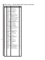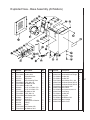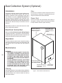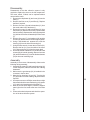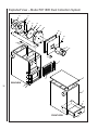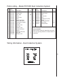
1
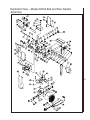
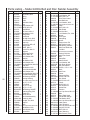
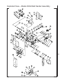
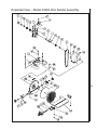
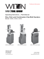
This Manual is Bookmarked
Operating Instructions — Parts Manual
Disc, Belt, and Combination Disc/Belt Sanders
Models: 4200A, 4300A, 4400A
4200A Disc/Belt Sander
WHM TOOL GROUP
2420 Vantage Drive
Elgin, Illinois 60123
Ph.: 800-274-6848
www.wmhtoolgroup.com
4300A 6 Inch Belt Sander
4400A 12 Inch Disc Sander
Part No. 5511365
Revision E2 10/04
Copyright © WMH Tool Group
This manual has been prepared for the owner and operators of a Wilton Sander. Its purpose, aside from
machine operation, is to promote safety using accepted operating and maintenance procedures. To obtain
maximum life and efficiency from your Sander and to aid in using it safely, please read this manual thoroughly
and follow instructions carefully.
Warranty and Service
WMH Tool Group warrants every product it sells. If one of our tools needs service or repair, one of our
Authorized Repair Stations located throughout the United States can provide quick service or information.
In most cases, a WMH Tool Group Repair Station can assist in authorizing repair work, obtaining parts, or
perform routine or major maintenance repair on your Wilton product.
For the name of an Authorized Repair Station in your area, please call 1-888-594-5866, or visit our web site at
www.wmhtoolgroup.com
More Information
Remember, WMH Tool Group is consistently adding new products to the line. For complete, up-to-date
product information, check with your local WMH Tool Group distributor, or visit our web site at
www.wmhtoolgroup.com
WMH Tool Group Warranty
WMH Tool Group makes every effort to assure that its products meet high quality and durability standards and
warrants to the original retail consumer/purchaser of our products that each product be free from defects in
materials and workmanship as follows: 1 YEAR LIMITED WARRANTY ON ALL PRODUCTS UNLESS
SPECIFIED OTHERWISE. This Warranty does not apply to defects due directly or indirectly to misuse,
abuse, negligence or accidents, normal wear-and-tear, repair or alterations outside our facilities, or to a lack
of maintenance.
WMH TOOL GROUP LIMITS ALL IMPLIED WARRANTIES TO THE PERIOD SPECIFIED ABOVE,
BEGINNING FROM THE DATE THE PRODUCT WAS PURCHASED AT RETAIL. EXCEPT AS STATED
HEREIN, ANY IMPLIED WARRANTIES OR MERCHANTABILITY AND FITNESS ARE EXCLUDED. SOME
STATES DO NOT ALLOW LIMITATIONS ON HOW LONG THE IMPLIED WARRANTY LASTS, SO THE
ABOVE LIMITATION MAY NOT APPLY TO YOU. IN NO EVENT SHALL WMH TOOL GROUP BE LIABLE
FOR DEATH, INJURIES TO PERSONS OR PROPERTY, OR FOR INCIDENTAL, CONTINGENT, SPECIAL,
OR CONSEQUENTIAL DAMAGES ARISING FROM THE USE OF OUR PRODUCTS. SOME STATES DO
NOT ALLOW THE EXCLUSION OR LIMITATION OF INCIDENTAL OR CONSEQUENTIAL DAMAGES, SO
THE ABOVE LIMITATION OR EXCLUSION MAY NOT APPLY TO YOU.
To take advantage of this warranty, the product or part must be returned for examination, postage prepaid, to
an Authorized Repair Station designated by our office. Proof of purchase date and an explanation of the
complaint must accompany the merchandise. If our inspection discloses a defect, we will either repair or
replace the product at our discretion, or refund the purchase price if we cannot readily and quickly provide a
repair or replacement. We will return the repaired product or replacement at WMH Tool Group’s expense, but
if it is determined there is no defect, or that the defect resulted from causes not within the scope of WMH Tool
Group’s warranty, then the user must bear the cost of storing and returning the product. This warranty gives
you specific legal rights; you may also have other rights, which vary from state to state.
WMH Tool Group sells through distributors only. Members of the WMH Tool Group reserve the right to effect
at any time, without prior notice, alterations to parts, fittings and accessory equipment, which they may deem
necessary for any reason whatsoever.
Table of Contents
Cover Page ......................................................................................................................................... 1
Warranty .............................................................................................................................................. 2
Table of Contents ................................................................................................................................ 3
Machine and Manual Overview ............................................................................................................ 4
General Specifications......................................................................................................................... 5
Warnings .............................................................................................................................................6
Operating Instructions ..........................................................................................................................8
Maintenance ...................................................................................................................................... 10
Setup and Installation ........................................................................................................................ 13
Troubleshooting ................................................................................................................................. 18
Wiring Diagrams ................................................................................................................................ 19
Replacement Parts ............................................................................................................................ 20
Accessories ....................................................................................................................................... 28
3
Machine and Manual Overview
Wilton Abrasive Finishing Machines are available in three
different configurations: disc, belt, and combination disc
and belt. Each configuration is a rugged, heavy-duty
machine designed for maximum high production work in
an industrial environment.
The speed of stock removal and the quality of finish
achieved is determined largely by the aggressiveness of
the abrasive disc or belt mounted on the machine. With
very aggressive grits, these machines are typically considered grinding machines. With very fine grits, these
machines are typically considered sanding machines.
Whatever you call them, and however you use them, the
instructions in this manual will help you use them safely
and productively.
You will note there are several types of electrical systems available for these machines. All of these systems
are equally effective in providing power to the grinding
mechanism -- however, local codes and the type of environment in which the machine is used will often be a
factor in your choice of system.
Instructions in this manual assume that you are using
one of the Model 4200A series Belt and Disc machines.
If you have a disc only, or belt only machine, you can
bypass those instructions which do not apply to you.
4
General Specifications
Disc Sander
Belt Sander
Disc/Belt Sander
Table size
12x16 3/8 in. (254x416mm)
7 3/8x14 3/4 in. (187x355mm)
Disc:12x16 3/8 in. (254x416mm)
Belt: 7 3/8x14 3/4 in.
(187x355mm)
Table tilt
45° down, 20° up
45° down, 20° up
(both) 45° down, 20° up
Miter gauge groove
3/8x3/4 in. (9.5x19mm)
3/8x3/4 in. (9.5x19mm)
(both) 3/8x3/4 in. (9.5x19mm)
Disc diameter
Disc Speed
Platen size
Belt size
Belt speed
Dimensions
(depth, W, H)
Dimensions w/platen
vertical (depth,W, H)
Dimensions w/platen
horizontal
(depth, W, H)
Motor options
12 in. (305mm)
1960 RPM
6 1/4x14 3/4 in. (159x375mm)
6x48 in. (152x1214mm)
2850 SFM
12 in. (305mm)
1960 RPM
6 1/4x14 3/4 in. (159x375mm)
6x48 in. (152x1214mm)
2850 SFM
19x16x57 1/2 in.
(475x400x1437mm)
25 1/2x16x43 in.
(637x400x1075mm)
19x16x57 1/2 in.
(475x400x1437mm)
25 1/2x16x43 in.
(637x400x1075mm)
Model 4300A 1 ph. 1.5HP
115/230V
Model 4301A 3 ph. 1.5HP
230V/460V
Model 4303A 3 ph. 1.5HP 230/
460V (connected 460) full JIC,
110V at the switch
Model 4200A 1 ph. 1.5HP
115/220V
Model 4202A 3 ph. 1.5HP
230V/460V
Model 4204A 3 ph. 1.5HP 230/
460V (connected 460) full JIC,
110V at the switch
211 lbs. (96 kg.)
250 lbs. (113 kg.)
Weight
29x17x42 3/4 in.
(1070x725x4250mm)
Model 4400A 1 ph. 1.5HP
115/230V
Model 4401A 3 ph. 1.5HP
230V/460V
Model 4403A 3 ph. 1.5HP
230/460V (connected 460)
full JIC, 110V at the switch
unassembled
164 lbs. (74 kg.)
5
General Machinery Cautions
- Misuse of this machine can cause serious injury.
- For safety, the machine must be set up, used and
serviced properly.
- Read, understand and follow the instructions in the
operator’s and parts manual which was shipped with
your machine.
When setting up the machine:
- Always avoid using the machine in damp or poorly
lighted work areas.
- Always be sure the machine is securely anchored to the
floor.
- Always keep the machine guards in place.
- Always put the start switch in the “OFF” position before
plugging in the machine.
When using the machine:
- Never operate the machine with safety guards missing.
- Always wear safety glasses with side shields (See ANSI
Z87.1)
- Never wear loose clothing or jewelry.
- Never overreach — you may slip and fall into the
machine.
- Never leave the machine running while unattended.
- Always shut the machine off when not in use.
When servicing the machine:
- Always unplug the machine from the electrical power
while servicing.
- Always follow the instructions in the operators and parts
manual when changing accessory tools or parts.
- Never modify the machine without consulting Wilton
Corporation.
You — the stationary power tool user — hold the key to safety.
Read and follow these simple rules for best results and full benefits from your machine. Used properly, Wilton’s
machinery is among the best in design and safety. However, any machine used improperly can be rendered inefficient
and unsafe. It is absolutely mandatory that those who use our products be properly trained in how to use them correctly.
They should read and understand the Operators and Parts Manual as well as all labels affixed to the machine. Failure
in following all of these warnings can cause serious injuries.
General Machinery Warnings
6
1. Always wear protective eye wear when operating machinery. Eye wear shall be impact resistant, protective safety
glasses with side shields which comply with ANSI Z87.1
specifications. Use of eye wear which does not comply
with ANSI Z87.1 specifications could result in severe injury
from the breakage of the eye protection.
2. Wear proper apparel. No loose clothing or jewelry which
can get caught in moving parts. Rubber soled, nonslip,
footwear is recommended for best footing.
3. Do not overreach. Failure to maintain a proper working
position can cause you to fall into the machine or cause
your clothing to get caught — pulling you into the machine.
4. Keep the guards in place and in proper working order.
Do not operate the machine with the guards removed.
5. Avoid dangerous working environments. Do not use stationary machine tools in wet or damp locations. Keep work
areas clean and well lit.
6. Special electrical precautions should be taken when
working on flammable materials.
7. Avoid accidental starts by being sure that the start switch
is in the “OFF” position before plugging in the machine.
8. Never leave the machine running while unattended. The
machine shall be shut off whenever it is not being used.
9. Disconnect the electrical power before servicing, whenever changing accessories or when general maintenance
is done on the machine.
10. Maintain all machine tools with care. Follow all maintenance instructions for lubricating and the changing of accessories. No attempt shall be made to modify or have
makeshift repairs done to the machine. This not only voids
the warranty but also renders the machine unsafe.
10. The machinery must be anchored to the floor.
11. Secure your work. Use clamps or a vise to hold your
work, when practical. It is safer than using your hands and
it frees both hands to operate the machine.
12. Never brush chips away while the machine is in operation.
13. Keep work area clean. Cluttered areas invite accidents.
14. Remove adjusting keys and wrenches before turning
the machine on.
15. Use the right tool. Don’t force a tool or attachment to do
a job it was not designed for.
16. Use only recommended accessories and follow manufacturers instructions pertaining to them.
17. Keep hands in sight and clear of all moving parts and
cutting surfaces.
18. All visitors should be kept at a safe distance from the
work area. Make your workshop completely safe by using
padlocks, master switches, or by removing starter keys.
19. Know the tool you are using — its application, limitations, and potential hazards.
General Electrical Cautions
Wire Sizes
This machine should be grounded in accordance with the
National Electrical Code and local codes and ordinances.
The work should be done by a qualified electrician. The
machine should be grounded to protect the user from electrical shock.
Caution: For circuits that are a great distance from the electrical service box, the wire size must be increased in order
to deliver ample voltage to the motor. To minimize power
losses and to prevent motor overheating and burnout, the
use of wire sizes for branch circuits or electrical extension
cords according to the following table is recommended:
Conductor length
AWG (American Wire Gauge) number
240 volt lines
0-50 feet
50-100 feet
Over 100 feet
No. 14
No. 14
No. 12
120 volt lines
No. 14
No. 12
No. 8
Safety Requirements for Abrasive
Sanding Machines
Abrasive sanding can be hazardous to operators and bystanders. Sanding sparks, chips and dust particles thrown
off by the sanding disc can cause serious injury if contacted or inhaled. To avoid such injuries you must comply
with the following safety requirements:
1. Always wear protective eyewear when operating machinery. Eye wear shall be impact resistant, safety glasses with
side shields which comply with ANSI Z87.1. Use of eye
wear which does not comply with ANSI Z87.1 specifications could result in severe injury from the breakage of the
eye protection.
2. Wear leather safety gloves, arm guards, leather aprons
and safety shoes.
3. A dust collection system is recommended, The operator
should also wear a dust mask at all times.
4. Additional precautions may be necessary for sanding
materials which are flammable or have other hazardous
properties. You should always consult the manufacturer of
such materials for instructions on sanding and handling.
5. Do not force or jam the workpiece into the sanding disc.
6. Before sanding, always allow the motor to come up to
operating speed, then check the sanding disc for wobble,
runout, or any unbalanced condition. If the disc is not operating accurately and smoothly, immediately stop the motor
and make repairs before attempting any sanding operations.
Figure A
Figure B
7. Abrasive discs must be stored in a controlled environment area. Relative humidity should be 35% to 50% and
the temperature should be between 60o and 80o Fahrenheit. Failure to do so could cause premature disc failure.
8. Examine the face of the sanding disc carefully. Excessive sanding that wears down to the backing material can
tear the disc. Never use a disc which shows backing, nicks
or cuts on the surface or edge or damage due to creasing
or poor handling.
9. When installing a new disc, be certain the disc is accurately centered on the drive wheel. Failure to do so could
cause a serious unbalanced condition.
10. Always present the workpiece to the wheel while resting the workpiece firmly on the table. Failure to do so could
result in damage to the workpiece or throwing of the
workpiece off the wheel.
11. Safety shoes which comply with ANSI Z41.1 should be
worn.
12. Personal hearing protection such as ear plugs or ear
muffs should be used to protect against the effect of noise
exposure.
7
Figure C
Figure D
Operating Instructions
These sanders can be used to remove stock from a
wide variety of machinable materials. Different materials
require different grit types and grades to achieve the desired stock removal rate and surface finish. Please consult
with your abrasive materials supplier for specific recommendations on the correct grit material and grade required
for your specific needs.
When removing stock from soft materials (wood, plastic, etc.) these machines are typically called "sanders."
When removing stock from hard materials (cast iron, steel,
etc.) they are referred to as "grinders". The word "sander"
is used, more-or-less consistently, throughout this manual.
It refers to the machines and not the type of abrasive finishing being performed.
Before operating your sander, please read the basic
instructions on safe machine usage on the preceding two
pages.
Belt Sander
The sanding belt must be in good condition, at proper
tension, and tracking correctly, before doing any sanding,
grinding or other abrasive machining operations. Refer to
the section on Track Mechanism Maintenance if you have
any problems with belt tension or tracking.
Adjusting the Belt Sander Table
You can tilt the table in a range between 20o upward
and 45o downward. A single locking handle on the side of
the table is used to lock and unlock the table to permit
adjustment.
There are two positive lock stop positions: at 90o (that
is, at a right angle to the platen) and at 45o downward (essentially 90o + 45o or 135o total to the platen.)
To Tilt the Belt Sander Table:
8
1. Unlock the locking handle on the side of the table.
2. Using the pointer and scale, set the angle to any required angle between 20o upward and 45o downward.
3. Lock the lock handle.
To Tilt the Table to Exactly 45o:
1.
2.
3.
4.
Flip out the stop bracket (see Figure 20).
Unlock the locking handle.
Move the table until it contacts the stop bracket.
Lock the table lock handle.
CAUTION: NEVER ADJUST THE TABLE ANGLE
WHILE THE SANDER IS RUNNING. ALWAYS TURN
THE MOTOR OFF BEFORE ADJUSTING THE TABLE
ANGLE.
Figure 1: Locking handle for belt table
Using the Indexing Lock Handle
The lock handle is spring loaded and can be repositioned on its shaft to permit easy locking and unlocking.
To Reposition the Handle:
1. Pull outward against its spring.
2. Rotate the handle to the position you require.
3. Release the handle and its spring will return it to the
correct operating position.
Adjusting the Belt Sander Arm
The arm which holds the sanding belt can be positioned at a full vertical position, a full horizontal position, or
at any angle in between which is convenient to the type of
sanding you are doing.
A positive stop mechanism is used to permit quick
adjustment to the vertical or horizontal positions.
To Adjust to Vertical:
1. Unlock both of the lock bolts. These are located under
the arbor cover.
2. Move the arm to vertical until it contacts its stop.
3. Tighten both of the lock bolts, and replace arbor cover.
To Adjust to Horizontal:
1. Unlock both of the lock bolts.
2. Move the arm to horizontal until it contacts its stop. (See
Figure 3.)
3. Tighten both of the lock bolts and replace arbor cover.
To Adjust the Arm to Any Angle Between
Vertical and Horizontal:
1. Unlock both of the lock bolts.
2. Use a machinist's protractor and level to set the arm to
the required angle.
3. Tighten both of the lock bolts and replace arbor cover.
Adjusting the Disc Sander Table
1. Unlock the two locking knobs underneath the table at
each end. (See Figure 4.)
2. Using the pointer and scale, set the angle to any required angle between 20o upward and 45o downward.
3. Lock the two locking knobs underneath the table.
CAUTION: NEVER ADJUST THE TABLE ANGLE
WHILE THE SANDER IS RUNNING. ALWAYS TURN
THE MOTOR OFF BEFORE ADJUSTING THE TABLE
ANGLE.
Figure 2: Lock bolts for belt arm
Use of the Miter Gauge
Figure 3: Arm at horizontal -- note that the table is removed.
The table may be removed or left in position, and may also
be set to any angle to allow horizontal sanding of various
angles.
The miter gauge can be used on either the disc or
belt surfaces to sand accurate angles on workpieces. When
using the gauge, alone, you sand a single angle. However,
by tilting the table and using the miter gauge in combination with the table tilt, it is possible to sand compound
angles, as well.
When grinding a compound angle you should always check the accuracy of your setup by sanding a piece
of scrap material before doing any finish sanding on the
actual workpiece.
1. Set the angle you wish to sand using the scale on the
miter gauge.
2. Tighten the miter gauge securely so the miter reference
surface will not move while you are sanding.
3. Place the workpiece against the miter reference surface
and slide it along the reference surface and into the sanding disc or belt. The basic method is shown in Figure 5,
below.
CAUTION: NEVER ADJUST THE ARM ANGLE
WHILE THE SANDER IS RUNNING. ALWAYS TURN
OFF THE MOTOR BEFORE ADJUSTING THE ARM
ANGLE.
9
Figure 5: Use of the miter system
Figure 4: Disc sander table adjustment
Maintenance
Belt Replacement
10
1. Disconnect the power to the machine to prevent accidental start-ups. If the machine is plugged into an outlet,
unplug it. If the machine is hardwired to a branch circuit
with a junction box, remove the fuse or trip the circuit breaker
to the branch.
2. Remove the lock knob and top cover (See Figure 6).
3. Remove the side guard and table.
4. Release the belt tension by turning the tension handle
in a counterclockwise direction (See Figure 7). If the handle
is difficult to turn, perform Track Mechanism Maintenance
according to the instructions following this section.
5. Remove the belt.
6. Check the drums and platen for scoring or signs of
wear which might require service or replacement.
7. Check the height of the platen with a straight edge. If it
is not 1/32 in. above the drums, adjust it according to the
instructions in Platen Replacement or Adjustment in the
Machine Setup section of this manual.
8. Check the drums for looseness which might cause
tracking problems. Correct any loose condition by tightening or replacing any parts as required.
9. Slip the new belt onto the drums and platen.
10. Adjust the tension handle clockwise until the belt is flat
against the platen and there is no curling or buckling of the
belt in the middle.
11. Turn the drums by hand to see if the belt tracks moreor-less true. JUST BECAUSE THE OLD BELT TRACKED
CORRECTLY DOES NOT MEAN THE NEW BELT WILL.
Always check the tracking when replacing a belt.
12. To adjust the tracking:
12.1. Plug the machine back into the outlet or
reestablish power in the branch.
12.2. Loosen the tracking lock knob.
12.3. Jog the motor on and off as necessary to
observe the tracking, and turn the tracking knob as
necessary to make the belt track in the center of the
platen and drums. Turn the tracking knob clockwise to
move the belt toward the right and counterclockwise to
move the belt toward the left.
12.4. When the belt seems to be tracking correctly, turn
the motor on and leave it running while fine tuning the
tracking.
12.5. Lock the tracking lock knob.
12.6. When the lock knob is secure, turn the power
off and disconnect the machine from the outlet or
branch as in Step 1, above.
13. Replace the table, side guard, top cover and lock
knob by reversing steps 3 and 2, above.
14. If you have not already done so, reconnect the power
to the machine and return it to service.
Figure 6: Top cover components
Figure 7: Belt adjustment components (Note top cover
removed for removal and replacement of belt.)
Track Mechanism Maintenance
Replacing the V-Belt.
While the use of a dust collection system can extend
service intervals, an accumulation of dust will almost certainly require periodic cleaning of the tracking mechanism.
The more continuous the use of the machine, the more
frequently this maintenance should be performed.
As mentioned in the preceding section, the need for
required maintenance is often indicated by difficulty in adjusting the tension/tracking mechanism.
1. Disconnect the power to the machine to prevent accidental start-ups.
2. Remove the belt guard (Figure 9) and disc table
3. Remove the table tilt lock knob (Figure 10).
Maintenance:
1. With the belt removed according to the instructions in
Belt Replacement, pull out the upper tracking system and
clean away all built up material in the upper part of the
bracket casting.
2. Take the two keys off of the idler pin bracket, wipe off, and
re-grease.
3. Reverse the above steps to make the machine ready for
reinstallation of the belt according to the Belt Replacement
instructions.
Installing Abrasive Discs
1. Disconnect the power to the machine to prevent accidental start-ups.
2. Peel off the old abrasive disc.
3. Clean the drive disc surface using naptha or a similar
nonflammable solvent that will dry film-free.
4. Pull the protective backing half off the new abrasive disc.
5. Position the new disc carefully so it is centered accurately on the drive disc. (See Figure 8.)
6. When accurately centered, remove the rest of the protective backing and press the abrasive disc firmly against the
drive disc so complete adhesive contact is made.
7. Reconnect the power to the machine.
Figure 9: Removing belt guard
11
Figure 10: Disc table lock knob
Figure 8: Installing new abrasive disc
3. Loosen the four motor bolts so the motor can slide on
its plate.
4. Remove the belt from the motor pulley.
5. Remove three of the base mounting bolts, then loosen
the fourth bolt slightly. This allows you to rotate the machine on the machine base (See Figure 11).
Figure 13: Removing the guard and drive disc, together.
Figure 11: Rotating the machine casting to remove the disc
guard bolts
6. Remove the two bolts, underneath the machine casting,
that secure the disc guard to the casting (See Figure 11).
12
Figure 12: Locating the set screws that secure the disc to
the arbor
5. Through the hole in the disc guard casting, locate and
remove the TWO set screws that secure the drive disc to
the arbor. One set screw clamps on the arbor key and the
other clamps on the arbor shaft, itself. Be sure you loosen
both of them.
6. Slide the disc and its guard off of the machine, together
(See Figure 13).
7. The V-belt can now be removed from the drive arbor.
8. Install the new belt on the top pulley.
9. Slide the disc and guard back into position.
10. Reinstall the disc guard bolts underneath the table.
11. Position the drive disc so that it is no more than 1/16
inch away from the table, then tighten BOTH of the set
screws by inserting the hex wrench through the hole in the
disc guard casting.
12. Rotate the machine back onto its base and secure it
with all four mounting bolts.
13. Install the belt over the bottom pulley.
14. Tension the belt so that when pressed, in the middle of
its travel, it has no more than one belt's width of movement
-- then tighten the four motor bolts.
15. Observe the alignment of the motor pulley and arbor
pulley. If necessary, correct their alignment by shifting the
motor slightly on its mount (which involves loosening and
retightening the mounting bolts and checking tension) or
by shifting the pulley slightly on the motor shaft (which involves loosening the motor pulley set screw and sliding
the pulley into alignment) or by moving the arbor pulley
slightly on its shaft (See Figure 14).
16. When the pulleys are accurately aligned, reinstall the
belt guard.
17. Reestablish electrical power to the machine.
Machine Setup
Basic Setup
Figure 14: Loosening pulley set screws to allow the
adjustment of pulley on arbor shaft.
1. Position the machine where it will be located on the
shop floor. When positioning the machine, consider the
type of work which will be done on it so you allow sufficient
room not only for the workpieces, but also for service to the
machine.
2. Open the door in the base of the machine and, using the
holes in the base as a template, mark the floor for the
position of the hold-down bolts.
3. Move the machine to expose the hold-down bolt marks
and install anchors for the hold-down bolts.
4. Put the machine back over the hold-down anchors and
bolt the machine securely to the shop floor. THIS MUST BE
DONE FOR SAFE OPERATION OF THE MACHINE.
5. Establish an electrical service connection to the machine. This will vary according to the model purchased. ALL
ELECTRICAL CONNECTIONS SHOULD BE MADE BY A
QUALIFIED ELECTRICIAN WHO IS FAMILIAR WITH YOUR
STATE AND LOCAL CODES. Many models of these machines make use of high voltages which pose a significant
risk of serious injury or DEATH if proper knowledge and
precautions are not used. Electrical instructions are included in the Electrical section of these Machine Setup
instructions.
6. Machines with belts are shipped with the belts in slack
condition. During the electrical hookup phase of machine
setup, the belt will have to be tightened and checked for
tracking. See the Belt Replacement section for instructions
on this procedure.
13
Disc Table Angle Adjustment
1. Disconnect the power to the machine to prevent accidental start-ups.
2. Loosen the table locking knobs on either end of the
table.
3. Using a machinist's square against the table and disc,
set the table at exactly 90o to the disc (See Figure 15).
4. Tighten the table locking knobs.
5. Check the pointer. If it is not exactly on the zero mark,
loosen the pointer attaching screw, adjust the pointer, and
retighten the screw.
6. Reconnect the power to the machine.
Figure 16: Using an adjustable square to set the table
parallelism.
Figure 15: Using a square to check the disc table scale.
Disc Table Miter Parallelism
Adjustment
14
1. Disconnect the power to the machine to prevent accidental start-ups.
2. Set the table angle to zero.
3. Place a scale or adjustable machinist's square against
either the left or right edge of the disc face and measure the
distance to the miter slot edge (See Figure 16).
4. Move the measuring device to the opposite edge of the
disc and measure the distance to the miter slot.
5. Adjust the table by loosening the four attachment screws
under the table, then move the table until the distance between the miter slot and the disc is equal on both sides
(See Figure 17).
6. Tighten the four attachment screws.
7. Reconnect the electrical power to the machine.
Figure 17: Table attachment screws -- loosen to adjust
miter groove parallelism.
Disc Table Gap Adjustment
1. Using a scale, check the gap between the edge of the
table and the face of the disc. It should be very close to 3/32
inch. If it is much more or less than that distance, adjust it
as follows:
2. Disconnect the electrical power to the machine.
3. Using the access hole on the top of the disc guard,
locate and loosen the two set screws that secure the disc
to the shaft.
4. Slide the disc in or out along its shaft until the table-todisc gap is 3/32 inch (See Figure 18).
5. Tighten both set screws.
6. Reconnect the electrical power to the machine.
Figure 18: Table-todisc gap
measurement.
Belt Table Miter Slot Parallelism
Adjustment
1. Disconnect the power to the machine to prevent accidental start-ups.
2. Set the table angle to zero.
3. Place a scale or adjustable machinist's square against
either the left or right edge of the belt or platen and measure the distance to the miter slot edge (See Figure 19).
4. Move the measuring device to the opposite edge of the
belt or platen and measure the distance to the miter slot.
5. Adjust the table by loosening the three attachment screws
under the table, then move the table until the distance between the miter slot and belt or platen is equal on both
sides.
6. Tighten the three attachment screws.
7. Reconnect the electrical power to the machine.
Belt Table Angle Adjustment
1. Loosen the table locking handle and tilt the table
upward to about 15o.
2. Flip out the stop bracket (See Figure 21).
3. Lower the table until its adjusting screw touches
the stop bracket.
4. Place a machinist's square against the table and
belt or platen.
5. If adjustment is required, turn the adjusting screw
(Figure 20) until the table is exactly square to the platen.
6. Check the pointer. If it is not on 0o, loosen the
pointer screw and adjust the pointer until it is on 0o.
7. Tighten the pointer screw.
8. Loosen the table lock handle and tilt the table until
its stop contacts the 45o stop position.
9. Using a machinist's protractor set on 135o (90o +
45o) adjust the screw until the table and platen are in
correct adjustment. DO NOT reset the pointer after
this operation.
Figure 19: Using an adjustable square to check and
set miter slot parallelism on the belt table.
15
Figure 20: Location of adjustment (socket head)
screws and pointer attachment screw for table angle
adjustment.
Figure 21: Locations of stop lugs and stop
bracket for zero and 45o table positions.
Adjusting or Replacing the Platen
Electrical
1. Disconnect the electrical power to the machine to prevent accidental start-ups.
2. Remove the top cover, side guard and belt as outlined in
Belt Replacement.
3. Remove the table by unscrewing the locking handling
and lifting the complete table assembly, from the machine.
4. If you are replacing the platen, remove the three screws
that hold it to its mount -- then install the new platen and
replace the mounting screws finger tight.
5. If you are only adjusting the platen, loosen the three
mounting screws to allow adjustment.
6. Using a straight edge as shown in Figure 22, adjust the
platen height until it is 1/32 inch higher than the crown of
both the drive and idler drums.
7. Tighten the platen adjustment screws.
8. Reinstall the table and belt.
9. Check and adjust, if necessary, the tracking of the belt
according to instructions in Belt replacement.
10. Reinstall the guards and covers.
11. Check and adjust the table angles and miter slot
squareness, according to table adjustment instructions in
this manual.
12. Reconnect the electrical power to the machine.
Caution: Wilton sanders are available in a wide variety of electrical configurations to meet the needs of the
purchaser with respect to power available and compliance
with electrical codes. Each machine is tested at the factory
for operation before shipment and the power cord is tagged
with the power requirements for the machine, as shipped.
HOWEVER, before attempting any electrical hookup, you
should be certain:
1. The electrical characteristics of the service branch match
the requirements of the motor.
2. The service branch is equipped with wires of the required gauge or size.
3. The branch circuit intended for the machine is protected
with a time delay fuse or circuit breaker with a rated amperage just slightly greater than the full load current of the
motor.
MOTOR AMPERAGE full load current
Phase
Voltage
Amperage
1
115
20
1
220
10
3
3
220
440
5.2
2.6
CAUTION: All electrical service work on your
Wilton sander should be performed by a qualified,
licensed electrician who is familiar with all safe standard electrical installation practices and all applicable electrical codes. This includes local electrical codes which may affect the connection and operation of the Wilton sander in your specific manufacturing operation.
16
Figure 22: Method for adjusting height of platen above drive
and idler drums.
Single Phase Electrical Hookup
Three Phase Electrical Hookup
When connecting your machine to single phase
power, you may be connecting to either 115 or 230 volts,
depending upon the motor type provided. Local codes may,
or may not, permit the use of a plug type of connection for
your machine. Where a plug connection is permitted, the
following installation practices must be followed:
1. The plug used must be a grounding type of plug. That is,
on a 115 volt single phase connection, the plug must be a
three-prong plug with two flat, parallel blades for the power
wires and a single rounded or U-shaped prong for the
ground connection. On 230 volt single phase connections,
the lug must be a three prong plug with two flat blades in
tandem to carry the current, and a third round or U-shaped
prong for the ground connection.
2. The service branch to which the plug is connected must
be a branch with a separate ground wire so the grounding
prong of the plug can be connected to ground effectively.
Note: Local electrical codes in many jurisdictions
DO NOT ALLOW THE USE OF PLUG TYPE CONNECTIONS
FOR SINGLE PHASE POWER WHEN THE MACHINE IS USED
IN A COMMERCIAL OR INDUSTRIAL ESTABLISHMENT.
In these cases you must connect your machine to
the service branch using a hardwired junction box connection.
1. Be certain the power to the branch you are connecting is
off and locked out, so power cannot be reestablished accidentally.
2. Connect the ground wires. These wires will be either
green, or green with a white stripe.
3. Connect the remaining three cable wires to the three
power wires in the service branch.
4. Reestablish the power to the branch.
Motor Rotation
The motor should be turning counterclockwise,
the belt sander should be moving downward and the disc
sander should be turning clockwise. If this is the case, the
machine can be considered wired correctly. If the motor is
not turning in the correct direction, take the following corrective action:
1. Disconnect power in the branch again and be certain it
cannot be accidentally turned on while you correct the wiring.
2. Reverse ANY TWO of the power wires to the machine.
3. Reestablish the power to the machine.
4. Turn the machine on. The motor should now be turning
in the correct direction.
Motor Rotation
The motor should be turning counterclockwise, the
belt sander should be moving downward, and the disc
sander should be turning clockwise. These motors are
wired at the factory for correct rotation.
Voltage Conversion
Voltage Conversion
Single phase machines are pre-wired for 115V or
230V per customer request. If it becomes necessary to
change the voltage, remove the back cover from the base
and place the machine on its side. Remove the terminal
cover from the motor. Rewire the motor according to the
motor connection diagram, (Figure 32 or, Figure 33).
Different electrical plugs are required depending on which
voltage you select. This completes the voltage conversion
process.
Three phase machines are pre-wired for 230V or
460V per customer request. If it becomes necessary to
change the voltage, remove the back cover from the base
and place the machine on its side. Remove the terminal
cover from the motor. Rewire the motor according to the
motor connection diagram, Figure 32 or, Figure 33). This
completes the voltage conversion process
Circuit Protection
Circuit Protection
Where the service branch is protected with a fuse or
circuit breaker that has too high a value to offer protection to
the motor supplied, a fuse or circuit breaker box should be
used at the point where the machine connection is made
and the time delay fuse or circuit breaker should be a value
just slightly higher than the maximum load current draw.
17
Troubleshooting
Fault
Motor will not run
Probable cause
1. Motor is defective
2. Voltage is too low
3. Switch is defective
4. Branch circuit fuse is blown or
the circuit breaker is tripped
5. Branch is shut down for service
6. Open circuit in the wiring
Motor stalls easily
1. Low voltage.
2. Fuse is blown (three phase
motors only.)
3. Improper wiring.
Abrasive belt or disc slows
down although motor keeps
running at working speed
Poor tracking
Suggested remedy
1. Replace the motor.
2. Check the power supply for the proper
voltage.
3. Replace the switch.
4. Determine the reason for the blown fuse
or tripped circuit breaker -- then replace
the fuse or reset the breaker.
5. Check all personnel and machines on
the branch to be certain someone has
not shut down the branch for service. DO
NOT replace the fuse or reset the breaker
unless you are certain no personnel are
working on the machines, wires or con
trols in the circuit.
6. Inspect all the wire connections for loose
or open connections.
1. Check for proper voltage at the motor
-- correct as necessary.
2. Replace the blown fuse.
3. Check for proper connections.
1. Belt is slipping
1. Replace the belt.
1. Tracking is out of adjustment.
2. Too much belt tension.
1. Adjust the belt tracking.
2. Loosen the tension until the belt is just
taut.
3. Tighten the tension until the belt is more
taut.
4. Check the belt for an irregular seam or
shape.
5. Remove the belt and put a straight edge
along the drive roller. There should be a
slight crown (high spot toward the middle
of the roller.) If the crown has worn away,
replace the roller.
6. Check all the bearings for excessive heat
or loose shafts. Replace if necessary.
3. Not enough belt tension.
4. Belt is jointed improperly.
5. Lack of crown on the drive roller.
18
6. Worn bearings.
Unsteady belt
1. Slack in the abrasive belt.
1. Adjust the belt tension.
Short belt life
1. Excessive pressure applied while
grinding.
1. Allow the belt to do the cutting. Excessive
pressure only dulls the grit and removes it
from the cloth.
2. Use all the surface areas of the abrasive
cloth.
3. Check with your abrasives supplier for rec
ommendations on the type and coarse
ness of the abrasive required for the
workpieces you are sanding or grinding.
2. Working on only one side of the belt
or only in one area of the disc.
3. Incorrect abrasive material or grit
size.
CAUTION: For all of the electrical faults and corrections in the above table Wilton recommends the use of a qualified
and licensed electrician for all circuit tracing, diagnosis and repair.
Electrical Schematics
JIC Packages
Figures 25 and 26, below: Wiring diagrams for 230 and 460 VAC with controller with warning light.
Figure 27 and 28, below: Wiring diagrams for 230 and 460 VAC with push button switch.
19
Electrical Schematics
Standard 1 phase and 3 phase machines
Figure 30: Schematic diagram for single phase motor.
Figure 31: Schematic diagram for 3-phase motor.
Figure 32: Motor connection diagram for 1-phase motor.
Figure 33: Motor connection diagram for 3-phase motor.
Replacement Parts
20
This section provides exploded view illustrations that show the replacement parts for the Model 4400A, 4300A,
4200A Disc, Belt, and Combination Disc/Belt Sanders. Also provided are parts listings that provide part number
and description. Item numbers shown on the illustration relate to the item numbers in the facing parts listing.
Order replacement parts from:
WMH Tool Group
2420 Vantage Drive
Elgin, Illinois 60123
Phone: 800-274-6848
www.wmhtoolgroup.com
Identify the replacement part by the part number shown in the parts listing. Be sure to include the model
number and serial number of your machine when ordering replacement parts to assure that you will receive the
correct part.
Exploded View – Model 4200A Belt and Disc Sander
Assembly
21
Parts Listing – Model 4200A Belt and Disc Sander Assembly
22
Ref #
1
2
3
4
5
6
7
8
9
10
11
12
13
14
15
16
17
18
19
20
21
22
23
24
25
26
27
28
29
30
31
32
33
34
35
36
37
38
39
40
41
42
43
44
45
46
47
48
49
50
51
52
53
54
55
Part No.
Description
Qty.
5508427
Bracket
1
5511833
Square Nut, M10
1
50510801 Spring
1
5051091
Sleeve
1
5051131
Collar
1
5508431
Shaft with Collar
1
5051151
Cap
1
TS-2361051 Lock Washer, M5
2
TS-1513051 SHFS, M5 x 25
2
5051721
Hand Wheel
1
5511818
FH Screw, M5 x 6
4
TS-1550071 Flat Washer, M10
2
5508432
Tilting Table
1
5508450
Hand Knob
4
5508429
Belt Adj. Knob, M10
1
5511824
Drive Screw, M2 x 5
5
5508437
Stop Lock
1
5511828
Groove Pin, M5 x 45
1
5051351
Tilting Scale
1
TS-1523011 SHSS, M6 x 6
2
5511827
Groove Pin, M4 x 8
2
5051331
Segment
1
5511725
4200 Arbor Pulley
1
TS-1504061 SHCS, M8 x 30
4
TS-2361081 Lock Washer, M8
4
5508433
Trunnion
1
TS-1550061 Flat Washer, M8
9
TS-2361081 Lock Washer, M8
9
TS-1490041 Hex Cap Screw, M8 x 25 3
5508435
Stud, M10
1
TS-1550071 Flat Washer, M10
4
5508436
Acorn Nut and Handle
1
TS-2361061 Lock Washer, M6
3
TS-1482031 Hex Cap Screw, M6 x 16 3
5508439
Preload Bushing, M54
1
BB-6205ZZ Ball Bearing, 6205ZZ
1
5508438
Bearing Housing
1
2
TS-2210951 Hex Cap Screw, M10 x 140
5051421
Key, 5 x 5 x 70
1
5508441
Drive Shaft
1
5051451
Key, 5 x 5 x 35
1
4200A-042 Key, 5 x 5 x 55
1
BB-6204ZZ Ball Bearing, 6204ZZ
1
5051471
Retaining Ring, S20
1
VB-A59
V-Belt, A59
1
TS-2245081 SHFS, M5 x 8
4
5508444
Belt Guard Assembly
1
4200A-048 Warning Label
1
TS-1540071 Hex Nut, Full, M10
5
5508446
Stop Pin
1
5508447
Base
1
TS-2210801 Hex Cap Screw, M10 x 80
4
5515292
Flat Washer, M10
8
TS-2361101 Lock Washer, M10
6
5051841
Garnet Belt
1
Ref #
56
57
58
59
60
61
62
63
64
65
66
67
68
69
70
71
72
73
74
75
76
77
78
79
80
81
82
83
84
85
86
87
88
89
90
91
92
93
94
95
96
97
98
99
100
101
102
103
104
105
106
107
108
109
110
Part No.
Description
5508455
Deflector Plate
TS-2361051 Lock Washer, M5
TS-1513021 SHFS, M5 x 12
5508454
Drive Drum Guard
5508456
Dust Deflector
TS-2361101 Lock Washer, M10
TS-1491021 Hex Cap Screw, M10 x 20
5508457
Platen
TS-1514011 SHFS, M6 x 12
5051601A Side Guard
TS-1540231 Hex Nut, M24
9058121
Lock Washer, Ext., M24
5051981
Spacer
5051971A Drive Drum
5508458
Clamp Ring
4200A-071 Spacer
5051031
Tension Lever Pin
5051021
Belt Tension Lever
BB-6202ZZ Ball Bearing, 6202ZZ
5508461
Idler Drum Shaft with
Lock Nut
TS-2342121 Hex Nut, Nylon Lock M12
5508460
Bearing Lock Nut
5051591A Idler Drum Guard
5508462
Stud
5508463
Clamp Bar
5052121
Bottom Guard
TS-2361061 Lock Washer, M6
5052061B Idler Drum Spacer
5508459
Idler Pin Bracket
TS-0367061 Roll Pin, 1/4" x 1-1/4"
5052001
Block
5052061A Idler Drum
5508434
Pointer
5508451
Clamp with Pins
4200A-090 Roll Pin, M6 x 45
5508453
Disc Guard
TS-2239551 SHCS, M10 x 55
5051741
Pointer
TS-1523031 SHSS, M6 x 10
5051641
Disc, Aluminum
5051631
Garnet Disc
5051681
Trunnion
TS-1490041 Hex Cap Screw, M8 x 25
5508449
Table
5051701
Tilting Table Scale
5052271
Deluxe Miter Gauge
TS-1550071 Flat Washer, M10
TS-1482032 Hex Cap Screw, M6 x 17
4200A-104 Label, Name
4200A-105 Label, Direction
TS-1482081 Hex Cap Screw, M6 x 40
TS-1540041 Hex Nut, Full, M6
TS-1523021 SHFS, M6 x 8
4200A-109 Label, Warning
TS-152704 Allen Wrench, 4mm
Qty.
1
2
2
1
1
3
3
1
2
1
1
1
1
1
1
1
1
1
2
1
1
2
1
1
3
2
1
4
2
1
2
2
2
1
2
4
1
2
1
2
1
1
2
4
1
1
1
2
4
1
2
2
2
1
1
1
Exploded View – Model 4300A Belt Sander Assembly
23
Parts Listing – Model 4300A Belt Sander
24
Ref #
1
2
3
4
5
6
7
8
9
10
11
12
13
14
15
16
17
18
19
20
21
22
23
24
25
26
27
28
29
30
31
32
33
34
35
36
37
38
39
40
41
42
43
44
45
46
47
48
49
50
51
Part No.
Description
5508427
Bracket
5511833
Square Nut, M10
5051081
Spring
5051091
Sleeve
5051131
Collar
5508431
Shaft with Collar
5051151
Cap
TS-2361051 Lock Washer, M5
TS-1513051 SHFS, M5 x 25
5051721
Hand Wheel
5511818
Flat Head Screw, M5 x 6
TS-1550071 Flat Washer, M10
5508432
Tilting Table
5508450
Hand Knob
5508429
Belt Adj. Knob, M10
5511824
Drive Screw, M2 x 5
5508437
Stop Lock
5511828
Groove Pin, M5 x 45
5051351
Tilting Scale
TS-1523011 SHSS, M6 x 6
5511827
Groove Pin, M4 x 8
5051331
Segment
5511725
4200 Arbor Pulley
TS-1504061 SHCS, M8 x 30
TS-2361081 Lock Washer, M8
5508433
Trunnion
TS-1550061 Flat Washer, M8
TS-2361081 Lock Washer, M8
TS-1490041 Hex Cap Screw, M8 x 25
5508435
Stud, M10
TS-1550071 Flat Washer, M10
5508436
Acorn Nut and Handle
TS-2361061 Lock Washer, M6
TS-1482033 Hex Cap Screw, M6 x 18
5508439
Reload Bushing, M54
BB-6205ZZ Ball Bearing, 6205ZZ
5508438
Bearing Housing
TS-2210951 Hex Cap Screw, M10 x 140
5051421
Key, 5 x 5 x 70
5508442
Drive Shaft
5051451
Key, 5 x 5 x 35
TS-1482034 Hex Cap Screw, M6 x 19
BB-6204ZZ Ball Bearing, 6204ZZ
5051471
Retaining Ring, S20
VB-A59
V-Belt, A59
TS-2245081 SHFS, M5 x 8
5508445
Belt Guard Assembly
4200A-048 Label, Warning
TS-1540071 Hex Nut, Full, M10
5508446
Stop Pin
5508448
Base
Qty.
1
1
1
1
1
1
1
2
2
1
4
1
1
2
1
3
1
1
1
2
2
1
1
4
4
1
3
3
3
1
4
1
3
3
1
1
1
2
1
1
1
4
1
1
1
4
1
1
5
1
1
Ref #
52
53
54
55
56
57
58
59
60
61
62
63
64
65
66
67
68
69
70
71
72
73
74
75
76
77
78
79
80
81
82
83
84
85
86
87
88
89
90
91
92
93
94
95
Part No.
TS-2210801
TS-1550071
TS-2361101
5051841
5508455
TS-2361051
TS-1513021
5508454
5508456
TS-2361101
TS-1491021
5508457
TS-1514011
5051601A
TS-1540231
9058121
5051981
5051971A
5508458
4200A-077
5051031
5051021
BB-6202ZZ
5508461
Description
Qty.
Hex Cap Screw, M10 x 80 4
Flat Washer, M10
8
Lock Washer, M10
6
Garnet Belt
1
Deflector Plate
1
Lock Washer, M5
2
SHFS, M5 x 12
2
Drive Drum Guard
1
Dust Deflector
1
Lock Washer, M10
3
Hex Cap Screw, M10 x 20 3
Platen
1
SHFS, M6 x 12
2
Side Guard
1
Hex Nut, M24
1
Lock Washer, Ext., M24
1
Spacer
1
Drive Drum
1
Clamp Ring
1
Idler Drum Shaft
1
Tension Lever Pin
1
Belt Tension Lever
1
Ball Brearing, 6202ZZ
2
Idler Drum Shaft with
1
Lock Nut
TS-2342121 Hex Nut, Nylon Lock, M12 2
5508460
Bearing Lock Nut
1
5051591A Idler Drum Guard
1
5508462
Stud
1
5508463
Clamp Bar
2
5052121
Bottom Guard
1
TS-2361061 Lock Washer, M6
4
5052061B Idler Drum Spacer
2
5508459
Idler Pin Bracket
1
TS-0367061 Roll Pin, 1/4" x 1-1/4"
2
5052001
Block
2
5052061A Idler Drum
2
5508434
Pointer
1
5052271
Deluxe Miter Gauge
1
4300A-090 Label, Name
1
4200A-105 Label, Direction
1
TS-1482081 Hex Cap Screw, M6 x 40
2
TS-1540041 Hex Nut,Full, M6
2
4300A-094 Label, Warning
1
TS-152704 Allen Wrench, 4mm
1
Exploded View – Model 4400A Disc Sander Assembly
25
Parts Listing – Model 4400A Disc Sander Assembly
26
Ref #
1
2
3
4
5
6
7
8
9
10
11
12
13
14
15
16
17
18
19
20
21
22
23
24
25
26
27
28
29
30
31
32
33
34
35
36
37
38
39
40
41
42
43
44
45
46
Part No.
Description
5508427
Bracket
TS-1523011 SHSS, M6 x 6
5511725
4200 Arbor Pulley
TS-1504061 SHCS, M8 x 30
TS-2361081 Lock Washer, M8
5508443
Drive Shaft
5051451
Key, 5 x 5 x 35
4200A-042 Key, 5 x 5 x 55
BB-6204ZZ Ball Bearing, 6204ZZ
5051471
Retaining Ring, S20
VB-A59
V-Belt, A59
5511818
Pan Head Screw, M5 x 6
5508444
Belt Guard Assembly
BB-6205ZZ Ball Bearing, 6205ZZ
5508439
Locking Bushing
TS-1550061 Flat Washer, M8
TS-1490031 Hex Cap Screw, M8 x 20
4400A-018 Glue Bushing
4200A-105 Label, Direction
4400A-020 Label, Warning
4400A-021 Label, Warning
TS-1540071 Hex Nut, Full, M10
TS-2210801 Hex Cap Screw, M10 x 80
TS-1550071 Flat Washer, M10
5508447
Base
TS-1550071 Flat Washer, M10
TS-2361101 Lock Washer, M10
5508450
Hand Knob
5508451
Clamp with Pins
4200A-090 Roll Pin, M6 x 45
5508462
Stud
5508453
Disc Guard
TS-2361101 Lock Washer, M10
TS-2239551 SHCS, M10 x 55
5051741
Pointer
TS-1523021 SHFS, M6 x 8
TS-1523031 SHSS, M6 x 10
5051641
Disc, Aluminum
5051631
Garnet Disc
5508449
Table
5051681
Trunnion
TS-2361081 Lock Washer, M8
TS-1490041 Hex Cap Screw, M8 x 25
5051701
Tilting Table Scale
5511824
Drive Screw, M2 x 5
5052271
Deluxe Miter Gauge
Qty.
1
2
1
4
4
1
1
1
1
1
1
4
1
1
1
1
1
1
1
1
1
4
4
8
1
2
4
2
2
4
2
1
2
2
1
1
2
1
1
1
2
4
4
1
2
1
Exploded View - Base Assembly (All Models)
Ref #
301
302
303
304
305
306
307
308
309
309
310
311
312
313
314
315
316
317
318
319
Part No.
5511743
TS-1540081
5511745
5511729
5052431
TS-1490031
TS-1550061
TS-1540061
5514650
5514651
TS-1550061
TS-1490011
TS-2361081
9133081
5514703
5511753
5511754
9139391
TS-2361081
TS-2360121
Description
Enclosure
Hex Nut, M12
Adjustable Mount
Large Cover
Motor Mounting Plate
HHCS, M8 x 20
Flat Washer, M8
Hex Nut, M8
1.5 HP 115/230V 1 Ph.
1.5 HP 115/230V 1 Ph.
Flat Washer, M8
HHCS, M8 x 12
Lock Washer, M8
Power Cord
Switch Box
Tapping Bolt w/ Washer
Bushing
Switch
Lock Washer, M8
Flat Washer, M12
Qty.
1
4
4
1
1
7
7
7
1
1
4
4
7
1
1
2
1
1
4
4
Ref #
320
321
322
323
324
325
326
327
328
329
330
331
332
333
334
335
Part No.
Description
Qty.
4200A-B320 Cover
1
4200A-B321 Pan Head Bolt w/ Flange
3
TS-1540041 Hex Nut, M6
3
TS-1540031 Hex Nut, M5
2
TS-0733203 Lock Washer, Ext., #10
2
4200A-B325 Pan Head Screw, M5 x 8
2
TS-2284082 Pan Head Screw, M4 x 8
2
TS-2361041 Lock Washer, M4
4
4200A-B328 Label, Name
1
TS-1533052 Pan Head Screw, M5 x 16
1
4200A-B330 Cord Clamp
1
TS-1540031 Hex Nut, M5
1
4200A-B332 Wiring Nut
3
TS-1550021 Flat Washer, M4
6
4200A-B334 Label, Voltage
1
4200A-B335 Switch Cover
1
27
Dust Collection System (Optional)
Installation
Transport the shipping container to the installation site.
Unpack the dust collection system and check for
damage. Contact the carrier if damage is found. Open
the installation kit (refer to Optional Accessories in
the parts listing for installation kits). Install the cover
and debris collection drawer if removed. Slip a hose
clamp over the 3-inch vacuum hose. Slip the hose on
the inlet duct. Move the clamp over the duct to secure
the hose.
Filter
Check for accumulation of debris. Replace the filter at
intervals that you determine are appropriate for your
shop environment and machine utilization.
Drawer Seal
Check the drawer seal periodically and replace if
damaged or missing. Keep the seal in good condition
to help maintain collection system efficiency.
Repeat the procedure to connect the hose to the outlet
duct on the grinding machine.
Electrical Connection
ON/OFF switch on
motor at rear of dust
collection system
Refer to the Dust Collection System Wiring Diagram
for wiring information. Connection to electrical power
should be made by a qualified electrician. Observe local
electrical codes when connecting the machine.
Removable cover –
remove for interior
cleaning/access to
impeller
Second Inlet
Duct on this side
Operation
The dust collection system motor is started by setting
the toggle switch on the motor to the ON position. Set
the switch to OFF to shut down the dust collection
system.
Maintenance
WARNING:
·
28
·
MAKE SURE YOU DISCONNECT THE ELECTRICAL POWER TO THE DUST COLLECTION SYSTEM BEFORE PERFORMING MAINTENANCE.
FAILURE TO DO SO MAY RESULT IN INJURY
TO THE OPERATOR AND/OR MAINTENANCE
PERSONNEL.
DO NOT OPERATE THE DUST COLLECTION
SYSTEM WITH THE COVER REMOVED. INJURY
TO FINGERS AND HANDS FROM THE FAN
BLADES, AND INGESTION OF LOOSE FITTING
CLOTHING INTO THE AIR INLET WITH
RESULTANT INJURY IS ALSO POSSIBLE.
Outlet filter at rear
removes fine debris
from outlet air stream
Inlet Duct – Connect
3 inch hose - secure
with clamp
Chip Drawer Pull to Open
Cleaning
Periodically dispose of accumulated chips and debris
from the chip drawer. Use a brush to loosen debris from
internal surfaces. Use a vacuum cleaner to clean up
the loosened debris.
Figure 1: Dust Collector Assembled View
Disassembly
Disassembly of the dust collection system is only
required to replace the motor or the fan components.
The motor switch, if failed, can be replaced without
removal of the motor.
1. Remove the chip drawer (2) and cover (4) from the
base (1).
2. Remove the filter cover (5) and filter (6). Replace
the filter if required.
3. Remove five nuts (10) and lock washers (11) from
the studs at the rear of the base (1).
4. Remove four nuts (12) and lock washers (13) from
the screws (14). Remove the screws (14) from inside
the fan housings. Separate the motor support panel
(9) (with fan and motor still attached) from the base
(1).
5. Remove five nuts (17), lock washers (18) and the
screws (19) that secure the fan housings together.
6. Using a flat bladed tool, separate the outer fan
housing (16) from the inner fan housing (24).
7. Using an Allen wrench, loosen the set screw (22).
Remove the fan (21) from the shaft of the motor
(25). Remove the key (23) from the motor shaft.
8. Use a flat-bladed screwdriver to hold the flat head
screws (28) (in inner fan housing). Remove four nuts
(26) and lock washers (27) from the flat head screws
(28) in the motor mounting lugs.
Assembly
Assembly is the reverse of disassembly. Observe the
following during assembly:
1. Assemble the motor (25) and inner fan housing (24)
on the rear panel; make sure the fan duct is facing
downward.
2. Make sure the guard strap (20) is installed in the
recesses in the fan duct.
3. Mate the fan housings (16 and 24). Turn the fan
(21) by hand to check for rubbing. Adjust the fan as
required.
4. Use a spare screw or a Phillips screwdriver to align
the screw holes in the outer fan housing (16), spacer
(15), and in the internal panel of the base (1).
5. With the screw holes aligned, install the support
panel (9) on the five studs at the rear of the base
(1).
6. Connect the electrical power and check the operation of the dust collection system.
29
Exploded View – Model 5511885 Dust Collection System
15
14
16
21
22
26
24
28
19
9
20
12
23
13
18
27
17
11
25
10
5
4
6
REAR VIEW
30
7
8
1
2
FRONT VIEW
3
Parts Listing – Model 5511885 Dust Collection System
Ref.
No.
1
2
3
4
5
6
7
8
9
10
11
12
13
14
15
16
17
18
Part
Number
5514731
5514732
5514733
5514734
5514735
5514779
5514736
5514737
5514738
5514739
5514740
5514741
5514742
5514743
5514744
5514745
5514746
5514747
Description
Base
Drawer, Chip
Seal, Tape
Cover
Cover, Filter
Filter
Panel, Rear Foam
Panel, Side Foam
Panel, Motor Support
Nut, Hex
Washer, Lock
Nut, Hex
Washer, Lock
Screw, Hex Head
Spacer
Housing, Outer Fan
Nut, Hex
Washer, Lock
Qty
1
1
*AR
1
1
1
1
2
1
5
5
4
4
4
1
1
5
5
Ref.
No.
19
20
21
22
23
24
25
26
27
28
Part
Number
5514748
5514749
5514750
5514751
5514752
5514753
5514754
5514755
5514756
5514757
Description
Screw, Hex Head
Strap, Guard
Fan
Screw, Set
Key
Housing, Inner Fan
Motor
Screw, Hex Head
Seal, Tape
Switch, Motor
Qty
5
1
1
1
1
1
1
4
*AR
1
Connection Kits:
Refer to Wilton catalog for appropriate connection
kit for your grinding machine, or contact Wilton for
assistance.
Wiring Information - Dust Collection System
31
WMH Tool Group
2420 Vantage Drive
Elgin, Illinois 60123
Phone: 800-274-6848
www.wmhtoolgroup.com