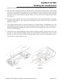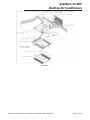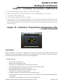
1
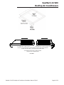
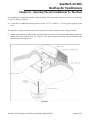
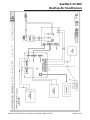
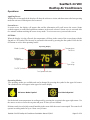
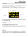
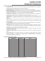
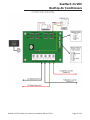
SeaMach 24 VDC
Rooftop Air Conditioners
SeaMach 24 VDC Rooftop
Air Conditioner
Installation Manual
24 VDC Rooftop Air Conditioner
Chapter 1: Safety Considerations .......................................................................... 2
Chapter 2: General Information . ........................................................................... 3
Chapter 3: Air Conditioning Sizing ......................................................................... 3
Chapter 4: Selecting an Installation Location . ........................................................ 4
Chapter 5: Installing the Roof Top Unit .................................................................. 4
Chapter 6: Securing the Air Conditioner to the Roof . .............................................. 8
Chapter 7: Electrical Wiring .................................................................................. 9
Chapter 8: Installing the Ceiling Assembly (9000 Series) ....................................... 11
Chapter 9: Completing the Installation (9000 Series) ............................................ 14
Chapter 10:Installation, Programming and Operation of the o-Touch Thermostat...... 14
Chapter 11:Maintenance....................................................................................... 20
Manufactured by:
Marvair Division of AIRXCEL , Inc
®
PO Box 400 • Cordele, GA 31010
156 Seedling Dr. • Cordele, GA 31015
(229) 273-3636 • Fax (229) 273-5154
Email: [email protected]
www.marvair.com
Marvair Marine UK
®
®
Unit B8 • Arena Business Centre • Holyrood Close
Poole, Dorset BH17 7FL.
+44 1202 606405
www.marvair.co.uk
SeaMach 24 VDC Rooftop Air Conditioner Installation Manual 5/2013
P/N 01991 5/2013
New
Page 1 of
20
SeaMach 24 VDC
Rooftop Air Conditioners
Chapter 1 - Safety Considerations
These instructions are a general guide for installing the SeaMach 24 VDC roof top air conditioners. For
specific air conditioner details, it will be necessary to refer to the printed Customer Envelope Package
supplied with each air conditioner.
IMPORTANT NOTICE:
These instructions are for the use of qualified individuals specially trained and experienced in
installation of this type equipment and related system components.
Installation and service personnel are required by some states to be licensed. PERSONS NOT
QUALIFIED SHALL NOT INSTALL NOR SERVICE THIS EQUIPMENT.
NOTE:
The words “Shall” or “Must” indicate a requirement which is essential to satisfactory and safe product
performance.
The words “Should” or “May” indicate a recommendation or advice which is not essential and not
required but which may be useful or helpful.
Safety Considerations
This is the safety alert symbol
. When you see this symbol on the Marvair® unit and in the instruction
manuals be alert to the potential for personal injury. Understand the signal word DANGER, WARNING
and CAUTION. These words are used to identify levels of the seriousness of the hazard.
DANGER Failure to comply will result in death or severe personal injury and/or property damage.
WARNING Failure to comply could result in death or severe personal injury and/or property damage.
CAUTION Failure to comply could result in minor personal injury and/or property damage.
IMPORTANT is used to point out helpful suggestions that will result in improved installation, reliability
or operation.
!
WARNING - SHOCK HAZARD
To prevent the possibility of severe personal injury or equipment damage due to electrical shock,
always be sure the electrical power source to the appliance is disconnected.
CAREFULLY FOLLOW ALL INSTRUCTIONS AND WARNINGS IN THIS BOOKLET TO AVOID
DAMAGE TO THE EQUIPMENT, PERSONAL INJURY OR FIRE.
!
WARNING
Improper installation may damage equipment, can create a hazard and may void the warranty.
The use of components not tested in accordance with these units will void the warranty, may make the
equipment in violation of state codes, may create a hazard and may ruin the equipment.
SeaMach 24 VDC Rooftop Air Conditioner Installation Manual 5/2013
Page 2 of 20
SeaMach 24 VDC
Rooftop Air Conditioners
Chapter 2 - General Information
OEM
Please make sure the Customer Envelope Package accompanies the air conditioner.
INSTALLER AND/OR DEALER
Please make sure the Customer Envelope Package is presented to the product consumer.
For more information about the contract, please review the sample contract located in the Operation and
Maintenance Instructions Booklet (Customer Envelope Package).
INQUIRIES ABOUT THE A/C UNIT
Inquiries to your Airxcel, Inc. representative or to Airxcel, Inc. pertaining to product installation should
contain both the model and serial numbers of the roof top air conditioner. All roof top air conditioning
units have model and serial number identification in two locations; (1) rating plate sticker may be viewed
by looking through the shroud louvers on the compressor side of the roof top air conditioning unit. The
rating plate sticker can be seen without removing the outer plastic shroud, (2) model/serial number sticker
(silver color) is located on the bottom of the basepan of the roof top air conditioner. If the air conditioner
is installed, the sticker may be viewed by lowering the ceiling assembly shroud.
Chapter 3 - Air Conditioning Sizing
The ability of an air conditioner to provide a comfortable environment for the consumer is dependent upon
the following conditions.
Air conditioners are rated primarily by their ability to remove heat. The thermal measurement used for
detecting a gain or loss of heat is the British Thermal Unit (BTU). One (1) BTU is the amount of heat
required to raise the temperature of one pound of water by one degree Fahrenheit. An air conditioner rated
at 13,500 BTUH can remove 13,500 BTU’s of heat in one hour.
The ability of an air conditioner to cool down a vehicle or maintain a consumer desired temperature is
dependent upon the heat gain of the vehicle. The physical size, the amount of window area, the quality
and amount of insulation, the position exposure to sunlight, the number of people using the vehicle and
the outside temperature may increase the heat gain to such an extent that the capacity of the air conditioner
is exceeded.
As a general rule, air supplied (discharge air) from the air conditioner will be 15°F to 20°F (11° C to
8.4°C) cooler than the air entering (return air) the ceiling assemblies bottom air grilles.
For example, if the air entering the air conditioner (the return air) is 80°F (26.7), the supply air (discharge
air) will be 60° to 65° F (11.1° to 18.3°C). As long as this temperature difference -15°F to 20° F (11° C to
8.4°C) is being maintained at the air conditioner, the air conditioner is operating properly.
SeaMach 24 VDC Rooftop Air Conditioner Installation Manual 5/2013
Page 3 of 20
SeaMach 24 VDC
Rooftop Air Conditioners
Again, give careful consideration to the heat gain variables. During extreme outdoor temperatures, the
heat gain of the vehicle or vessel may be reduced by:
•
•
•
•
Keeping the vessel in a shaded area
Keeping windows and doors closed
Avoiding the use of heat producing appliances
Using window shades (blinds and/or curtains)
For a more permanent solution to high heat gain situations, additional insulation, window awnings and/or
window glass tinting should be considered.
Chapter 4 - Selecting An Installation Location
Is the roof of the vehicle or vessel capable of supporting both the roof top unit and ceiling assembly without
additional support structures? Inspect the interior ceiling mounting area to avoid interference with existing
structural members such as: bunks, curtains, tracks or room dividers. The depth of the ceiling assembly
shroud is 3” (7.6 cm). Be sure to check clearance for doors which must be swung open (refrigerator,
closets, cabinets).
Chapter 5 - Installing The Roof Top Unit
!
DANGER - SHOCK HAZARD
DISCONNECT ALL POWER BEFORE PERFORMING ANY CUTTING. CONTACT WITH
HIGH VOLTAGE CAN RESULT IN EQUIPMENT DAMAGE, PERSONAL INJURY OR
DEATH.
!
CAUTION
TO PREVENT DAMAGE TO THE WIRING AND BATTERY, DISCONNECT THE BATTERY
CABLE FROM THE POSITIVE BATTERY TERMINAL BEFORE PERFORMING ANY
CUTTING TO THE VEHICLE OR VESSEL.
Once the location for your air conditioner has been determined (See Chapter 4), a reinforced and framed
roof hole opening must be provided (may use existing vent hole). Before cutting into the roof, verify that
the cutting action will clear all structural members and crossbeams. Additionally, the location of any inner
roof plumbing and electrical supplies must be considered.
A. If a roof vent is already present in the desired mounting location for the air conditioner, the following
steps must be taken:
1. Remove all screws which secure the roof vent to the vehicle. Remove the vent and any additional
trim materials. Carefully remove all caulking from around the roof vent opening to obtain clean
exterior roof surface.
2. It may be necessary to seal some of the old roof vent mounting screw holes which may fall outside
of the air conditioner basepan gasket.
SeaMach 24 VDC Rooftop Air Conditioner Installation Manual 5/2013
Page 4 of 20
SeaMach 24 VDC
Rooftop Air Conditioners
3. Examine the roof opening. If the opening is smaller than 14” x 14” (35.6 cm x 35.6 cm), the
opening must be enlarged. If the opening exceeds 15” x 15” 38 cm x 38 cm), a mounting frame
must be field fabricated to reduce the opening size (See Figure 1).
B. If a roof vent opening is not used, a new opening (See Figure 1) will have to be cut into the vehicle
roof. A matching opening will also have to be cut into the interior vehicle ceiling. Be careful when
cutting the ceiling opening.
After the opening in the roof and interior ceiling are the correct size, a framed support structure must
be provided between exterior roof top and interior ceiling. The reinforced framed structure must
provide the following guidelines:
1. Capable of supporting both the weight of the roof top air conditioner and the interior ceiling
assembly.
2. Capable of holding or supporting the roof outer surface and interior ceiling apart, so that when the
roof top air conditioner and ceiling assembly are bolted together, no collapsing occurs.
Airxcel’s SeaMach air conditioner requires that the spacing from the vehicle roof top to the interior
ceiling be no less than 1” (2.34 cm). A typical support frame is shown in Figure 1.
The frame must provide an opening to allow passage for the power supply wiring. Route the supply
wiring through the frame at the same time the support frame is being installed.
IMPORTANT – Allow 24” (61 cm)of supply wiring through the support frame (working length).
After the support frame is installed, seal off all gaps between the frame and both the roof exterior
and the interior ceiling of the vehicle or vessel (cavity walls). Additionally, seal the gap around the
electrical supply wiring.
C. This air conditioner is to be installed in accordance with NFPA Standard 501C.
D. The roof top air conditioner must be mounted as near level from front to rear and side to side as is
possible when the vehicle is parked on a level plane. Figure 2 shows maximum allowable degree
deviations (mounting degrees from total surface flat plane).
SeaMach 24 VDC Rooftop Air Conditioner Installation Manual 5/2013
Page 5 of 20
SeaMach 24 VDC
Rooftop Air Conditioners
15 DEGREE MAX. ABOVE LEVEL
15 DEGREE MAX. ABOVE OR BELOW LEVEL
NOTE: IF UNIT IS INSTALLED UNLEVEL FRONT TO BACK, THE NOSE OR FRONT
OF THE UNIT MUST BE UP. DO NOT INSTALL NOSE DOWN.
ALLOWABLE OFFSET FOR ALL HEAT PUMPS
WITH ROTARY COMPRESSORS.
FIGURE 2
FIGURE 3
SeaMach 24 VDC Rooftop Air Conditioner Installation Manual 5/2013
Page 6 of 20
SeaMach 24 VDC
Rooftop Air Conditioners
FIGURE 3
If the roof of the vehicle or vessel is sloped (not level) such that the roof top air conditioner cannot be
mounted within the maximum allowable degree deviations, an exterior leveling shim will need to be
added to make the roof top air conditioner level. A typical leveling shim is shown in Figure 3.
After the mounting hole area is properly prepared, remove the carton and shipping pads from the roof top
air conditioner. Carefully lift the unit to the top of the vehicle. Do not use the outer plastic shroud for
lifting. Place the roof top air conditioner over the prepared mounting hole. The pointed end (nose) of the
shroud must face towards the front of the vehicle or vessel. Pull the electrical conduit down from the roof
air conditioner through the mounting opening and let hang.
SeaMach 24 VDC Rooftop Air Conditioner Installation Manual 5/2013
Page 7 of 20
SeaMach 24 VDC
Rooftop Air Conditioners
Chapter 6 - Securing The Air Conditioner To The Roof
A mounting frame is supplied with the ceiling assembly. Follow the steps below to secure the air conditioner
to the roof. Refer to Figure 4.
A. Locate the air conditioner mount gasket over the 14” (35.6 cm)to 15” (38 cm) square opening in the
roof.
B. Install the ceiling assembly mount frame using the four bolts found with the ceiling assembly.
C. Proper tension has been achieved for each bolt when any portion of each gasket indicating tab has been
pulled down even with the roof. See Figure 4. The upper unit has now been properly installed with
optimum gasket compression.
FIGURE 4
SeaMach 24 VDC Rooftop Air Conditioner Installation Manual 5/2013
Page 8 of 20
SeaMach 24 VDC
Rooftop Air Conditioners
Chapter 7 - Electrical Wiring
ROUTING 24 VDC WIRING:
Following Airxcel’s low voltage wiring specifications and local National Electrical Codes (NEC), route
the Roof Top Unit 24VDC supply wiring from its power source to the wire box. Use the chart below as a
guide knowing the amp draw listed on the unit rating plate to size the minimum wire size for use for the
distance in feet between the unit and your power supply.
This is a five percent table which means at these amperage ratings at the listed distances, 5% of the power
would be lost to resistance.
24 VOLT DC CHART
Amps in Wire Watts at 24V
#14
#12
#10
#8
#6
#4
1
24
169
262
412
675
2
48
84
131
207
337
532
4
96
37
66
103
169
267
6
144
28
45
66
112
178
282
#2
1/0
2/0
3/0
8
192
21
32
54
84
133
216
10
240
17
26
43
67
107
169
270
15
360
11
17
26
45
71
112
180
289
20
480
13
21
37
54
84
135
217
270
343
25
600
17
26
43
67
108
172
217
274
30
720
13
22
36
56
90
144
180
228
40
960
17
26
43
67
108
135
171
50
1200
13
21
34
54
86
108
137
ELECTRIC CIRCUIT
DC POWER REQUIREMENT:
OPERATING CURRENT:
1243 Watts
13 - 40 Amps
MINIMUM CIRCUIT AMPACITY (DC AMPS):
50
Follow all local and NEC (National Electrical Code) for proper sizing of wire AWG based on
Overcurrent Protection Device selected and the length of the wiring run to the air conditioner.
!
DANGER - SHOCK HAZARD
MAKE SURE THAT ALL POWER SUPPLY TO THE UNIT IS DISCONNECTED BEFORE
PERFORMING ANY WORK ON THE UNIT TO AVOID THE POSSIBILITY OF SHOCK
INJURY OR DAMAGE TO THE EQUIPMENT.
SeaMach 24 VDC Rooftop Air Conditioner Installation Manual 5/2013
Page 9 of 20
SeaMach 24 VDC
Rooftop Air Conditioners
SeaMach 24 VDC Rooftop Air Conditioner Installation Manual 5/2013
Page 10 of 20
SeaMach 24 VDC
Rooftop Air Conditioners
!
DANGER
WHEN USING NON-METALLIC SHEATH CABLES (ROMEX, ETC.), STRIP SHEATH BACK
TO EXPOSE 4-6 INCHES OF THE SUPPLY LEADS.
STRIP THE INDIVIDUAL WIRE LEAD ENDS FOR WIRE CONNECTION (ABOUT 3/4” BARE WIRE). INSERT
THE SUPPLY WIRES INTO THE ELECTRICAL CONNECTOR CLAMP. SHEATH MUST PROTRUDE PAST
THE CLAMP BUSHING INSIDE THE BOX AS ILLUSTRATED. MAKE SURE SHEATH CABLE IS CENTERED
IN CLAMP BEFORE TIGHTENING UP ON IT. DO NOT OVERTIGHTEN!!
THIS COULD RESULT IN PINCHING THROUGH THE PLASTIC WIRE INSULATION AND CAUSE SHORTING
OR “HOT” WIRES TO GROUND (SHOCK HAZARD). THE CLAMP IS INTENDED FOR STRAIN RELIEF OF
THE WIRES. SLIGHT PRESSURE IS USUALLY SUFFICIENT TO ACCOMPLISH THIS.
IF OTHER THAN NON-METALLIC CABLES ARE USED FOR SUPPLY CONDUCTORS, APPROPRIATE
STRAIN RELIEF CONNECTORS OR CLAMPS SHOULD BE USED.
IN NO CASE SHOULD CLAMPING OR PINCHING ACTION BE APPLIED TO THE INDIVIDUAL SUPPLY
LEADS (NEUTRAL AND “HOT” WIRES).
!
DANGER - SHOCK HAZARD
TO PREVENT THE POSSIBILITY OF SHOCK INJURY, THE WHITE WIRE MUST BE CONNECTED TO
NEUTRAL IN THE SERVICE BOX ENTRANCE AND THE MECHANICAL GROUND MUST BE CONNECTED TO
A GROUNDING LUG EITHER IN THE SERVICE BOX OR THE MOTOR GENERATOR COMPARTMENT.
Chapter 8 - Installing The Ceiling Assembly (9000 Series)
Make sure that you have properly matched the roof top air conditioner and interior ceiling assembly.
The following step by step instructions must be performed in the following sequence to insure proper
installation.
A. A.Carefully uncarton the ceiling assembly. Controls are factory installed in the ceiling assembly
(except ceiling assemblies for applications with remote control box/thermostat).
B. Remove the grille and filters from the ceiling assembly.
C. Fasten the duct collar to the basepan of the air conditioner with three (3) screws (See Figure 7).
D. Plug the roof top air conditioner electrical conduit into the 9 position receptacle located in the thermostat
side of the ceiling assembly.
E. Insert the supply wiring through the cable clamp and into the field wiring box so that 4 - 6” (10 cm to
15 cm) of supply conductor is inside the box. Secure the cable clamp over the supply wire sheath so
that no movement is possible (See Figure 6).
F. Connect the supply power conductors to the black and white pigtail wires and the supply ground wire
to the green pigtail wire found in the field wiring box using the 3 provided wire nuts. IMPORTANT
– Connect the black supply to the black pigtail and the white supply to the white pigtail. Using a U.L.
SeaMach 24 VDC Rooftop Air Conditioner Installation Manual 5/2013
Page 11 of 20
SeaMach 24 VDC
Rooftop Air Conditioners
approved electrical tape, secure the wire nuts to wires in a workmanlike manner (See Figure 6).
G. Place the metal control box shield over the thermostat, switch and field wiring boxes. Make certain
that all wires are pushed into the control boxes or laying in the wireway between the thermostat and
switch boxes and will not be pinched by the control box shield. Control box shield is properly installed
when the two holes in the shield are aligned with the two screw holes in the ceiling assembly chute
(See Figure 5).
H. Raise the ceiling assembly and secure to the mounting frame with 4 provided shoulder screw/spring
assemblies. The front two screws should pass through the clearance holes in the metal control box
shield (See Figure 7).
I. The ceiling assembly shroud is curved to contour to a crowned ceiling. If installation is to a flat
ceiling and gaps are present on the sides of the shroud, insert the four optional 3/4 inch (19 mm)screws
(provided) through the mounting posts and secure them to the mounting frame above (See Figure 5,
6, & 7 for screw locations).
J. Pull the fabric duct material through ceiling assembly discharge opening. Peel the release liner from
the adhesive strip around the discharge opening. Press the fabric duct material firmly in place around
opening. Cut off excess fabric on inside of ceiling assembly chute with a box knife taking care not to
tear the fabric beyond the adhesive strip.
FIGURE 5
FIGURE 6
SeaMach 24 VDC Rooftop Air Conditioner Installation Manual 5/2013
Page 12 of 20
SeaMach 24 VDC
Rooftop Air Conditioners
FIGURE 7
SeaMach 24 VDC Rooftop Air Conditioner Installation Manual 5/2013
Page 13 of 20
SeaMach 24 VDC
Rooftop Air Conditioners
Chapter 9 - Completing The Installation (9000 Series)
A. Make sure the non-allergenic filters are properly positioned in the ceiling grille.
B. Install the ceiling grille by positioning on the bottom of the shroud and engaging the two 1/4 turn fasteners.
C. Turn the selector switch to OFF position
D. Turn ON the power supply to the roof top air conditioner.
E. System Checkout – Airxcel, Inc. manufactures a wide range of roof top air conditioners which incorporate different product
operation features. To properly evaluate the performance of a newly installed air conditioner, it is necessary to review the
specific unit operation characteristics (features) described in the product operation and maintenance instructions (Customer
Envelope Package).
Chapter 10 - Installation, Programming and Operation of the
o-Touch Thermostat
Introduction
When connected to a 12-24VDC controller, the versatile o-Touch DC digital display provides room
temperature control and humidity reduction in a small package. It allows for easy control of fan speed,
operating mode and temperature in a wide variety of applications.
Features Include:
•
•
•
•
•
•
•
•
•
•
Easy touch screen operation.
Built in room temperature sensor.
The display is compatible with Vimar and Gewiss frames.
Visual symbols enable the viewer to see the operating status at a glance.
Easily programmed for customized operation.
Both automatic and manual six level fan speed control.
De-icing cycle to prevent evaporator icing.
Automatic moisture mode provides relative humidity control.
Variable compressor speed control reduces power consumption as ambient temperature approaches
the set point.
Compressor current limiting can be used to prolong battery life.
SeaMach 24 VDC Rooftop Air Conditioner Installation Manual 5/2013
Page 14 of 20
SeaMach 24 VDC
Rooftop Air Conditioners
Operations
Applying Power:
When power is first applied, the display will show the software revision, and then return to the last operating
mode the unit was in when power was removed.
Screen Saver:
In screen saver, the display will appear dim and the information will scroll across the screen. Status
symbols appear as needed and operation continues in the mode selected. Screen saver is activated after
two minutes without touching the screen in any mode. To exit screen saver, just touch the screen.
Off Mode:
When the display is in the off mode, the temperature will show in the center of the screen along with the
fan and on / off symbol. The fan may be operated in this mode by pressing the fan symbol. Press the On/
Off button to access other operating modes.
Operating Display
Temperature
Set Point
Mode Symbol
Ambient
Temperature
Fan
Operating
I/O
On/Off Symbol
Fan Speed Indicator
Operating Modes:
Two operating modes are available and can be changed by pressing the symbol in the upper left corner.
The symbols below will appear in the upper left on the display.
Moisture Mode Symbol
Cool Mode Symbol
Set the desired room temperature in cooling mode by pressing the set point in the upper right corner. Use
the arrows to raise or lower the set point and press X when you are finished.
Moisture mode is used to help control humidity in the room while the room is unoccupied. The control will
operate in cooling mode for up to 1 hour every 6 hours.
SeaMach 24 VDC Rooftop Air Conditioner Installation Manual 5/2013
Page 15 of 20
SeaMach 24 VDC
Rooftop Air Conditioners
Operating the Fan:
Fan speed may be set for automatic (temperature dependent) or manual control. Press the fan operating
symbol in the bottom right corner to change speeds. Manually selected fan speed is indicated with the M
showing before the fan speed indicator. When the fan is automatically controlled, the M is not present. The
fan may be controlled in the cool, heat, automatic modes as well as in the off state.
Manual fan speed operation is not available when the compressor is not running if the “Cycled Fan”
option is set. Turn the unit off in this case and then manual fan operation may be used. Manual fan speed
operation is also not available in moisture mode.
System Status Screen
System Voltage
System Current
Motor Current
Motor
Temperature
Motor Speed
Several system operating parameters can be viewed during operation as shown above. Press and hold the
lower center of the display (where the fan speed indicator is located) to view this status. To exit the status
view, press anywhere on the display.
The system current is available at all times, the remaining items only during compressor operation.
Failure Messages:
The following fault messages will be shown on the display in the event of a failure:
AIR SENSOR TROUBLE: Failure of the display mounted air sensor.
MASTERFLUX GENERATED ERRORS: Errors generated by the Masterflux controller will also show
on the display. The exact text of these errors is dependent on the connected controller. See the operating
manual for your Masterflux controller for details and resolution of these errors.
Programmable Parameters
Program Mode:
To enter the program mode first put the unit in the off mode. Then press and hold the On/Off symbol for 3
seconds. Press the right arrow to advance to the next parameter and press the left arrow to go back to the
last parameter. Press the up or down arrows to change the parameters value. Exit the program mode when
finished by pressing the X or wait 60 seconds for the display to exit.
SeaMach 24 VDC Rooftop Air Conditioner Installation Manual 5/2013
Page 16 of 20
SeaMach 24 VDC
Rooftop Air Conditioners
Parameter Description:
• Cycled Fan: When set for “Cycled”, the fan will operate on demand. When set for “Continuous”,
the fan will always operate when the system is in cool mode.
• System Units: Degrees Fahrenheit (°F) or degrees Celsius (°C) can be selected
• Display Brightness: Display brightness can be set from 4 to 15 to suit room lighting conditions.
• Screen Saver Brightness: If set for (0) then a single bar will blink sequentially in the four corners
of the display. Values from 1 to 8 can be set to suit room lighting conditions.
• Temperature Calibration: This parameter allows the user to calibrate the room air temperature
sensor. The room temperature will be displayed and can be adjusted +/-10 °F or +/-5°C
• Staging Delay: The compressor staging delay is provided for multi system installations. Set the
Staging delays at different intervals so only one compressor starts at a time when power is
applied.
• De-Ice Time: If the compressor runs continuously for longer than one hour, the compressor will
shut down and the blower will run for the specified time. The compressor will then restart and
resume operation.
• Cycled Pump: When set for “Cycled”, the pump will run on demand. When set for “Continuous”,
the pump will run continuously when the system is in cool mode.
• Fan Speed 1-6: These parameters are used to optimize fan performance and airflow Speed 1
corresponds to the lowest speed setting. Speed 6 corresponds to the highest speed setting. Speeds
should be set to avoid system icing in humid environments.
• Maximum Comp Current: Thirty seconds after starting a cooling cycle the compressor current
will be limited to this value.
• Compressor Speed Range: The number of degrees from set point to maximum compressor
speed.
• Reset Parameters: To reset all parameters to factory defaults, select YES and then exit the program
mode by pressing the on / off button. The display will show “EEPROM RESET”, and then show
the room temperature in the off mode.
Programmable Parameters Table:
Description
Cycled fan
System units
Display brightness
Screen saver brightness
Temperature calibration
Staging delay
De-Ice time
Cycled pump
Fan A speed 1
Fan A speed 2
Fan A speed 3
Fan A speed 4
Fan A speed 5
Fan A speed 6
Compressor speed range
Maximum comp current
Reset Parameters
Default
Continuous
°F
15
4
0
15
2
Cycled
30
35
40
45
55
85
2 (1.1)
35
No
Value
Cycled or Continuous
°F or °C
4=Minimum 15=Maximum
- and 1-8
Ambient +/- 10°F
5-135 Seconds
1-5 Minutes
Cycled or Continuous
30-90
30-90
30-90
30-90
30-90
30-90
2-5 °F (1.1-2.8 °C)
Off, 10-60 Amps
No or Yes
SeaMach 24 VDC Rooftop Air Conditioner Installation Manual 5/2013
Page 17 of 20
SeaMach 24 VDC
Rooftop Air Conditioners
Specifications
Set point range
55°F to 85°F
12.7°C to 29.4°C
Ambient temperature range displayed
5°F to 150°F
-15°C to 65.6°C
Sensor accuracy
+/-2°F at 77°F
+/-1.1°C at 25°C
Evaporator Output MAX
10 Amps
Condenser Output MAX
10 Amps
System Current MAX
60 Amps
Minimum operating temperature
0°F
17.8°C
Maximum operating temperature
180°F
82.2°C
Maximum RH conditions
95% Non-condensing
Maximum length of the display cable 75 Feet
22.86 m
SeaMach 24 VDC Rooftop Air Conditioner Installation Manual 5/2013
Page 18 of 20
SeaMach 24 VDC
Rooftop Air Conditioners
SeaMach 24 VDC Rooftop Air Conditioner Installation Manual 5/2013
Page 19 of 20
SeaMach 24 VDC
Rooftop Air Conditioners
Chapter 11 - Maintenance
One of the biggest advantages to your air conditioner is that the maintenance needed to keep the unit in
good care is minimal. As the owner, your primary responsibility is the cleaning and replacement of the
filter(s). Filters are made from long life natural fibers which can be cleaned and reused.
If the filters are not cleaned at regular intervals, they may become partially clogged with lint, dirt, grease,
etc. A clogged filter will produce a loss of air volume and may eventually cause an icing-up of the cooling
(evaporator) coil. The filters should be cleaned or changed at least every two weeks when the air conditioner
is in operation.
Cleaning and/or changing the filters:
1. Disengage the two 1/4-turn fasteners that secure the ceiling assembly grille to the ceiling assembly
(See Figure 7).
2. Lower the grille and filter(s) from the ceiling assembly.
3. Take filter(s) out and either clean or exchange with other filters (See Figure 7).
4. If the vehicle is equipped with a flush mount ceiling assembly, remove the four return air grill
screws.
5. Remove filter from grill and either clean or exchange with new filter.
NOTE: If replacement filters are necessary, they can be purchased from most Authorized Service
Centers. It is recommended that spare filters be carried with the unit at all times to replace worn,
torn or deteriorated filters.
Service Person:
A. Electrical - All electrical work and/or inspection should be performed only by qualified service
personnel. Contact your nearest Service Center if electrical problems should arise.
B. Check Points - Failure to start or to cool the air are sometimes problems with air conditioning
units. The air conditioner is designed to operate on 24 VDC electrical power. If the compressor on
the air conditioner fails to start, check with your Service Center to determine that the proper wire
size is connected to the unit, the proper circuit breakers are installed as protection devices on the
electrical circuit. Refer to the chart on page 9 to determine if the proper size wire is being used.
Each air conditioning unit must be protected with a 50 amp time delay fuse or circuit breaker.
If the air conditioner continues to trip off the circuit breakers, have an electrician check the starting
amperage and running amperage on the unit. If the circuit breaker continues to trip off and the electrical
consumption is found to be normal, it will require the replacement of the faulty circuit breaker. If all
electrical power to the air conditioner is normal but neither the fan nor the compressor will operate,
the connector plug located behind the ceiling assembly control box should be checked to determine
whether it is faulty.
C. Mechanical Integrity - The air conditioner should be inspected periodically to be sure that the bolts
which secure the unit to the roof are tight and in good shape. Also, an examination of the plastic
shroud covering the air conditioner on the top of the roof should be made periodically. Be sure the four
mounting screws and washers are snug and holding the shroud to the air conditioner. Also examine the
shroud to be sure it is not developing cracks or has suffered damage from impact.
1976A520 (10-11) PP
Airxcel, Inc.
Marvair Division
156 Seedling Dr.
Cordele, GA 31015
SeaMach 24 VDC Rooftop Air Conditioner Installation Manual 5/2013
Page 20 of 20