1
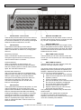
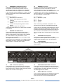
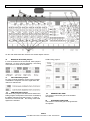
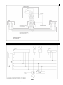
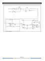
PS 630
SIX CHANNEL SPEAKER STATION
USER MANUAL
Issue 2011 © ASL Intercom BV
DESIGNED AND MANUFACTURED BY:
ASL INTERCOM BV
ZONNEBAAN 42
3542 EG UTRECHT
THE NETHERLANDS
PHONE: +31 (0)30 2411901
FAX: +31 (0)30 2667373
E-MAIL: [email protected]
WEB: www.asl-inter.com
PAGE 1
User Manual PS 630 / Issue 2011 © ASL Intercom BV
.
CONTENT OF THIS USER MANUAL
1.0
2.0
3.0
4.0
5.0
6.0
7.0
8.0
9.0
10.0
11.0
12.0
13.0
INTRODUCTION .............................................................................................3
UNPACKING ....................................................................................................3
INSTALLATION ...............................................................................................3
WARRANTY ....................................................................................................3
FRONT PANEL CONTROLS & CONNECTOR ................................................4
REAR PANEL CONTROLS & CONNECTOR...................................................5
INTERNAL CONTROLS...................................................................................6
TECHNICAL SPECIFICATIONS PS 630 .........................................................7
PARTY LINE, TECHNICAL CONCEPT ............................................................7
CABLING .........................................................................................................8
EARTHING CONCEPT ....................................................................................9
SYSTEM CONFIGURATION ...........................................................................9
PS 630 BLOCK DIAGRAM .............................................................................10
PAGE 2
User Manual PS 630 / Issue 2011 © ASL Intercom BV
.
1.0
INTRODUCTION
The PS 630 is a six channel speaker station
designed for use in both portable and fixed intercom
systems. It incorporates a loudspeaker and a
gooseneck microphone and provides full duplex
communications within an ASL intercom system.
The PS 630 RM model has a small built-in electret
microphone.
Special attention has been paid to the intelligibility of
speech. By applying low noise/high speed op-amps, a
speech presence filter and proprietary and bridged
headphone amplifiers, communication is very
comfortable even in environments with high background noise level. There are separate amplifiers for
headset and loudspeaker.
Each channel has a Volume (listen level) control, a
TALK and CALL button with LED indicators and a
two-stage side tone trimmer. A master volume
controls the speaker/headset volume.
The unique ASL CALL system provides both a
flashing red LED and a very distinctive characteristic
sound signal. Smooth operation is guaranteed with
the CALL button. Only a slight touch makes the red
LED flash, whilst holding the button for two seconds
activates the CALL sound signal. The volume of the
sound signal (buzzer) can be adjusted at the front
panel.
The unit is equipped with a limiter for the gooseneck
microphone, allowing to speak close into the
microphone without giving rise to overload and
distortion. Loudspeaker dimming is automatic when
the microphone is active. Private conversation may
be carried out with a headset or telephone handset
connected to the unit. When a headset is plugged in,
both gooseneck microphone and loudspeaker are
disabled automatically.
As an option, a XLR-5 headset connector can be
fitted for binaural use of the headset: each channel
can be assigned to either the left or the right headset
can, or to both headset cans.
The PS 630 has an electronically balanced program
audio input for local volume controlled monitoring
only. The program audio does not appear on the
intercom lines.
2.0
After unpacking the unit please inspect for any
physical damage to the unit, and retain the shipping
carton and relevant packing materials for use should
the unit need returning. If any damage has occurred,
please notify your dealer immediately so that a written
claim can be initiated. Please also refer to the
guarantee section of this manual.
INSTALLATION
This PS 630 may form part of an existing or new
intercom system. To connect the PS 630 to the
system, use professional flexible microphone cable
with 2 wires and 1 shield only. Connect the intercom
cables to the LINE connector sockets at the rear
panel.
4.0
Fully electronic switching increases reliability and
allows for :
'soft' microphone ON switching, latched or
momentary
remote Mic Mute facility
automatic speaker attenuation, when the
microphone is activated
UNPACKING
The shipping carton contains :
The PS 630
User manual
19” rack mount flares
If any are missing, contact your dealer.
ASL has taken great care to ensure this product
reaches you in flawless condition.
3.0
The pre-amplified microphone signal is electronically
balanced available at the ‘Mic Direct Out’ connector
at the rear panel. This signal may be sent to any PA
or paging system.
The PS 630 is fully protected against eventual wiring
mistakes (reverse power) or a short circuit in the
interconnect cables.
A special kit is included for mounting the PS 630 in a
19" rack, taking 2U of rack space.
WARRANTY
This unit is warranted by ASL Intercom to the original
end-user purchaser against defects in workmanship
and materials in its manufacture for a period of one
year from date of shipment to the end-user.
Faults arising from misuse, unauthorized
modifications or accidents are not covered by this
warranty. If the unit is faulty it should be sent in its
original packing, to the supplier or your local ASL
dealer, with shipping prepaid.
A note must be included stating the faults found and
a copy of the original suppliers invoice.
PAGE 3
User Manual PS 630 / Issue 2011 © ASL Intercom BV
.
5.0
FRONT PANEL CONTROLS & CONNECTOR
1
LISTEN LEVEL control knobs
These knobs preset the listen level for each intercom
channel. By turning the knob fully counter clockwise,
the channel is switched off. For receiving a Call signal
whilst the channel is switched off, see #17.
4
MASTER VOLUME knob
This knob functions as the master volume control of
the listen levels of the 6 intercom channels (see also
#1), for both the speaker and the headset.
2
TALK buttons
These buttons allow talking to each channel
separately or to some or all channels simultaneously.
When a TALK button is switched on, its large green
LED is lit.
5
PGM VOLUME knob
This knob adjusts the volume of the Program audio,
both for the speaker and the headset. Depending on
the setting of internal jumpers (see #18), the master
volume knob functions as a master control for both
PGM and intercom volume.
Momentary switching:
When a TALK button is pushed and held, the
microphone signal is sent to the referring intercom
channel until the button is released.
6
SIDE TONE LEVEL trimmers
These trimmers (one for each channel) control the
level of your voice as heard in your own loudspeaker
or headset.
Latched switching:
When a TALK button is pushed shortly, it is
electronically latched and the microphone signal is
sent to the referring intercom channel. When pushed
again, the Talk button switches off.
7
SIDE TONE HI trimmers
These trimmers (one for each channel) control the
rejection in the high frequency range.
Mic Mute when latched on:
After on an intercom channel a so-called Mic Mute
signal has been received from a PRO Series master
station or power supply the connection between
microphone and the referring intercom channel is
interrupted. By pushing the TALK button, the
connection is restored and one can talk to the
intercom channel again.
3
CALL buttons
These push buttons activate the call system, for each
channel separately. By a momentary push a call
signal is sent to all stations connected to the referring
intercom channel and all Call LED’s start flashing.
Pushing and holding the CALL button for 2 seconds
activates the call buzzer, if not muted by a Buzzer
Mute signal received from a PRO Series master
station or separate power supply. After the CALL
button is released the LED’s continue to flash for a
further 2 seconds.
The trimmers #6 and #7 also minimize the speaker
feeding back into the gooseneck microphone (unit
feedback). Adjustment procedure for both side tone
trimmers, for each channel separately:
set trimmer in start position : fully clockwise
switch off the microphones of all connected
(speaker-) stations
Connect a headset to this PS 630
push the TALK button of the channel of which
the side tone is supposed to be adjusted
turn up the listen volume of the PS 630.
speak into the headset microphone.
adjust the listen level (your own voice) by
turning the side tone trimmer.
The operating area is between fully clockwise and
minimum level.
For optimum result, repeat above mentioned
procedure for trimmers #6 and trimmer #7.
Adjusting side tones does not affect the level of your
voice as it is heard by other stations.
PAGE 4
User Manual PS 630 / Issue 2011 © ASL Intercom BV
.
8
SPEAKER ATTENUATOR trimmer
This trimmer adjusts the extent to which the
loudspeaker is automatically dimmed when the
gooseneck microphone is switched on. It prevents
unit feedback if side tone rejection is not sufficient.
It also minimizes system feedback or a 'hollow' sound
when the gooseneck mics of other speaker stations
are switched on.
10
HEADSET connector
An XLR-4 connector for the connection of a local
headset when private conversation is desired.
The headset must have a can impedance of
minimum 200 ohms. When the headset has two cans
in parallel, each can must have an impedance of
minimum 400 ohms. The headset microphone may
be of the dynamic or electret type.
Adjustment procedure :
switch off the TALK buttons
inject an audio signal into one of the
channels
turn up the listen volume of the selected
channel
activate the microphone (push the TALK
button)
adjust the degree of attenuation.
The speaker attenuator has no effect when a headset
is connected
Pin assignments :
Pin 1: Shield mic. (GND)
Pin 2: mic. +
Pin 3: phones +
Pin 4: phones -
9
BUZZER VOLUME trimmer
This trimmer adjusts the volume of the internal
buzzer, which is located behind the front panel.The
buzzer is activated if the CALL button of the PS 630
(or a CALL button of any other station on the
channels to which the PS 630 is connected) pushed
for longer than 2 seconds.
The buzzer may be muted after a so-called All Buzzer
Mute signal has been received from a PRO Series
master station or separate power supply.
6.0
When connecting a headset, loudspeaker and
gooseneck microphone are disabled automatically
The PS 630 can optionally be equipped with a XLR-5
headset connector for binaural use. Jumpers on the
internal front PCB (see #16) determine the routing of
each channel to the headset cans: either to the left
can, or the right can or to both cans or to none of the
cans.
11
GOOSENECK microphone
This is a high quality electret noise cancelling
microphone. A limiter prevents the mic pre-amp from
clipping when speaking close in the microphone.
12
LOUDSPEAKER
This is a high quality loudspeaker driven by a 2.9
Watt amplifier..
REAR PANEL CONTROLS & CONNECTOR
13
LINE connectors (A thru F)
These twelve XLR-3 connectors are for connecting
the PS 630 to the party lines of the intercom system.
Each channel has an XLR-3 female connector (input)
and an XLR-3 male connector (link).
14
PROGRAM AUDIO INPUT connector
This input is electronically balanced and accepts line
level signals. In case of binaural use of the PS 630, 2
internal jumpers (see #18) determine the routing of
the PGM signal to the headset.
15
DIRECT MIC OUT connector
This connector outputs the pre-amplified microphone
signal, electronically balanced. For output signal
levels see section 8 ‘Technical Specifications’.
PAGE 5
User Manual PS 630 / Issue 2011 © ASL Intercom BV
.
7.0
INTERNAL CONTROLS
On the main PCB inside the unit there are several adjust controls :
16
BINAURAL ROUTING jumpers
In case of binaural use of the PS 630, these jumpers
determine – for each channel separately - the routing
of the intercom audio to the headset.
PGM routing jumpers:
17
CALL RECEIVE jumpers
For each channel separately, these jumpers enable
or disable the reception of a CALL signal when the
channel is switched off.
18
PGM ROUTING jumpers
With these two jumpers one determines whether the
PGM (program audio) listen level is also controlled by
the Master Volume knob (see #4) and – in case of
binaural use of the PS 630 - the routing of the PGM
signal to the headset.
19
HEADSET MIC GAIN
This trimmer controls the gain of the headset
microphone.
20
GOOSENECK MIC GAIN
This trimmer controls the gain of the gooseneck
microphone.
.
PAGE 6
User Manual PS 630 / Issue 2011 © ASL Intercom BV
.
8.0
TECHNICAL SPECIFICATIONS PS 630
System
dynamic range: 80 dB
call send signal: +2.8 mA
call signal threshold (receive): +2.4 V DC
supply voltage: +30 V DC (12 - 32 V DC)
power interrupt time (mic mute): 0.1 sec
Intercom Line
Impedance: 350 Ω (1kHz), 2.2 kΩ (DC)
audio level: nom. -18 dBu, max. +4 dBu
Mic. Pre-amps
gooseneck mic: noise cancelling electret
headset mic. impedance: 200 Ω
gain: 40 - 60 dB (adjustable internally)
presence filter: +6 dB at 5 kHz
frequency response: 200 Hz - 13 kHz (-3 dB)
power to electret mic: +9 V DC
Headphones Driver Amps
max. output level:
monaural: 14 Vrms @ 200 Ω
binaural: 2x 10.6 Vrms @ 400 Ω
max. output power:
monaural: 1 Wrms @ 200 Ω
binaural: 2x 0.28 Wrms @ 400 Ω
Program Audio Input
input impedance: 11 kΩ (balanced)
nominal input level: -12 to + 6 dBU
max. input level: +21 dBu
Direct Mic Output
output impedance: 50 Ω (balanced)
nominal Output Level: + 6 dBu
max. Output Level: +24 dBu
Power Consumption PS 630
current (at 30 V DC):
105 mA quiescent, 140 mA signaling
280 mA at max. output + signaling
Side Tone
Rejection: 0 - 30dB adjustable
Buzzer
max. SPL: 85 dBA
Dimensions & Weight PS 630
width: 337mm / height: 87 mm
depth: 155 mm / weight: 2940 grams
Speaker Driver Amp
speaker impedance: 25 Ω
max. output power: 2.9 Wrms
0 dBu is defined as 775 mV into open circuit
ASL reserves the right to alter specifications without prior notice
9.0
PARTY LINE, TECHNICAL CONCEPT
User stations in an ASL intercom system are
connected via one or several 'party lines'. A party
line offers two way (‘full duplex’) communication and
consists of standard microphone (multi-pair) cable.
One wire is used as an audio line, one as a power
line and the screen of the cable functions as
earth/return.
Current drive is used for signal transfer. Each station
utilizes a current amplifier to amplify the microphone
signal and place it on the common audio line where,
due to the constant line impedance (situated in the
power supply between XLR pin 3 and 1), a signal
voltage is developed which can be further amplified
and sent to the headphones or loudspeakers.
This principle has three advantages:
the use of a single audio line allows several
stations to talk and listen simultaneously
due to the high bridging impedance offered
by each station, the number of stations on
the party line has no influence on the level of
the communications signal
power and audio to the intercom stations
use the same cable
The Call signal is also sent as a current on the audio
line. It develops a DC potential over the line
impedance which will be sensed by each station and
interpreted as a Call signal.
PAGE 7
User Manual PS 630 / Issue 2011 © ASL Intercom BV
.
10.0
CABLING
The intercom lines (the ‘party lines’) are of the shielded two-conductor microphone cable type. The intercom line
connectors are of the XLR-3 type. Audio and Call signals are on pin 3, DC power is on pin 2 and pin 1 is
connected to the shield of the cable which functions as the common return for audio and power.
The audio signal is transferred in an unbalanced way (see ‘Party Line, Technical Concept’).
To avoid earth loops (hum), the possible effect of electromagnetic fields and to minimize power loss, certain rules
have to be obeyed when installing the cabling of an intercom system :
Use high quality cable
Use high quality microphone cable (shielded two
conductor cable, minimum 2x 0.30 mm2).
In case multi-pair microphone cable is used, it
should be of high quality and each pair should
consist of two conductors (minimum 2x 0.15 mm2)
with separate shield and an overall shield.
Keep cables parallel as much as possible
When two (multi channel) units in a network are
connected by more than one cable, make sure that
these cables are parallel to each other over the
whole distance between those units. When using
multi-pair cable, parallelism is ensured in the best
possible way.
Use flexible cable
Use flexible single and multi-pair microphone cable
instead of cable with solid cores, especially when the
cable is subjected to bending during operation or
installation.
Avoid closed loops
Always avoid that intercom cables are making a
closed loop. So-called 'ring intercom' should not
physically be cabled as a ring..
Cable screens to XLR pin 1
The screen of each separate microphone cable
and/or the screen of each single pair in a multi-pair
cable, should be connected to pin 1 of each XLR-3
connector. Do not connect these screens to the
metal housing of ASL unitst or XLR-3 wall boxes.
See section ‘Earthing Concept’.
Connect metal cable trunks, wall boxes and
overall multi-pair cable screens to clean earth
Metal cable trunks, metal wall boxes and overall
multi-pair cable screens should be interconnected
and, at the 'central earth point' in the intercom
network only, be connected to a clean earth or a
safety earth. (see section ‘Earthing Concept’).
Keep metal connection boxes and cable trunks
or pipes isolated from other metal parts
Metal trunks or pipes for intercom cables and metal
connection boxes should be mounted in such a way
that they are isolated from any other metal housing
or construction part.
Keep cables away from electromagnetic sources
Keep intercom cables away from high energy cables,
e.g. 115/230/400V mains power or dimmer
controlled feeds for spotlights. Intercom cables
should cross high energy cables at an angle of 90º
only. Intercom cables should never be in the same
trunks as energy cables.
Place power supply in a central position
In case of a system powered by a separate power
supply: In order to diminish power losses, place the
power supply as close as possible to where most
power consumption occurs, in other words most
user stations are placed.
ASL powered units to a 'clean' mains outlet
Master stations or power supplies should be
connected to a mains outlet with a clean earth. Other
audio equipment may be connected to this mains
outlet, but avoid using an outlet which also powers
dimmer controlled lighting systems.
In case of more complex installations, don’t hesitate to contact us. Please send us a block diagram of the planned
intercom network with a list of all user stations and their positions, and we are happy to advise you on cabling lay
out
PAGE 8
User Manual PS 630 / Issue 2011 © ASL Intercom BV
.
11.0
EARTHING CONCEPT
12.0
SYSTEM CONFIGURATION
PAGE 9
User Manual PS 630 / Issue 2011 © ASL Intercom BV
.
13.0
PS 630 BLOCK DIAGRAM
PAGE 10
User Manual PS 630 / Issue 2011 © ASL Intercom BV
.
![User Manual PS 430 [ASL]](http://vs1.manualzilla.com/store/data/005978378_1-af53a31d0469f4c1b9fb526270e34a3a-150x150.png)
![User Manual PS 260 [ASL]](http://vs1.manualzilla.com/store/data/005875222_1-79f7ffd37f8e6cc3732f57605cc0b82b-150x150.png)
![User Manual PS 260 [ASL]](http://vs1.manualzilla.com/store/data/006916739_1-983cb380987130e2fe2cf762515f3398-150x150.png)

![User Manual PS 260 [ASL]](http://vs1.manualzilla.com/store/data/005887031_1-132c7eb8ac96774a27528798f7f3ad09-150x150.png)
![User Manual PS 260 [ASL]](http://vs1.manualzilla.com/store/data/005945478_1-a7dc8230481a9f04873ba664e1b890b7-150x150.png)