1
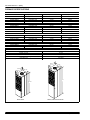
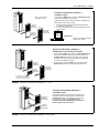
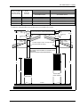
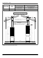
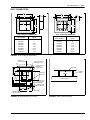
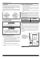
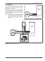
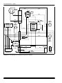
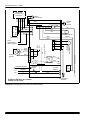
INSTALLATION
INSTRUCTION
SEALED COMBUSTION
DOWNFLOW GAS FURNACE
MODELS: DGAA, DGAH, DGPA, AND DGPH
TABLE OF CONTENTS
FURNACE SPECIFICATIONS . . . . . . . . . . . . . . . . .2
GENERAL INFORMATION . . . . . . . . . . . . . . . . . . . .3
INSTALLATION STANDARDS . . . . . . . . . . . . . . . . .3
CODE COMPLIANCE . . . . . . . . . . . . . . . . . . . . . .3
HIGH ALTITUDE INSTALLATION . . . . . . . . . . . .3
MINIMUM FURNACE CLEARANCES . . . . . . . . .3
RETURN AIR REQUIREMENTS . . . . . . . . . . . . . . . .4
CLOSET INSTALLATIONS . . . . . . . . . . . . . . . . . .4
AIR DISTRIBUTION SYSTEMS . . . . . . . . . . . . . .4
ROOF JACK . . . . . . . . . . . . . . . . . . . . . . . . . . . . . . .6
EXISTING FURNACE REPLACEMENT . . . . . . . .6
NEW HOME INSTALLATION . . . . . . . . . . . . . . . .6
INSTALLATION IN SNOW REGIONS . . . . . . . . .6
LOCATING AND CUTTING ROOF JACK
OPENING . . . . . . . . . . . . . . . . . . . . . . . . . . . . . . .6
INSTALLING ROOF JACK IN ROOF . . . . . . . . . .6
DUCT CONNECTORS . . . . . . . . . . . . . . . . . . . . . . .9
INSTALLATION OF SCREW ATTACHMENT
DUCT CONNECTOR . . . . . . . . . . . . . . . . . . . . .10
INSTALLATION OF TAB ATTACHMENT
DUCT CONNECTORS . . . . . . . . . . . . . . . . . . . .10
INSTALLATION OF THE FURNACE . . . . . . . . . . .11
CEILING RINGS . . . . . . . . . . . . . . . . . . . . . . . . .12
ELECTRICAL WIRING . . . . . . . . . . . . . . . . . . . . . .12
CONNECT POWER SUPPLY WIRES . . . . . . . .12
CONNECT THERMOSTAT WIRES . . . . . . . . . .12
WALL THERMOSTAT . . . . . . . . . . . . . . . . . . . . .13
For Installation In:
1.
Manufactured (Mobile) Homes
2.
Recreational Vehicles & Park Models
3.
Modular Homes & Buildings
IMPORTANT - Only individuals having proven experience with this
type of equipment should attempt to perform set-up.
Proper furnace set-up and adjustment is the responsibility of the
retailer/homeowner and is not covered under warranty.
FURNACE START-UP CHECK LIST
•
Has roof jack crown been correctly installed?
•
Has furnace gas valve and burner orifice been correctly converted for Propane. gas where applicable?
GAS PIPING . . . . . . . . . . . . . . . . . . . . . . . . . . . . . .19
•
INSTALLATION AND CHECKING OF GAS LINE 19
HIGH ALTITUDE DERATION CHART . . . . . . . .21
Has furnace gas valve been de-rated for altitudes above 2000
feet where applicable?
•
Is gas line outlet pressure properly set for fuel type? (natural gas
is 3.5" W.C.; Propane is 10" W.C.)
REPAIR PARTS LIST . . . . . . . . . . . . . . . . . . . . . . .22
•
Is cross-over duct installed per home builder and UPG installation instructions?
•
Has furnace been operated through a complete heating cycle?
•
Has the pilot flame been adjusted properly? (DGPH and DGPA
Models)
WIRING DIAGRAMS . . . . . . . . . . . . . . . . . . . . . . .14
CAUTION: READ ALL SAFETY GUIDES BEFORE
YOU START TO INSTALL YOUR UNIT.
SAVE THIS MANUAL
035-16328-002 Rev. C (0902)
035-16328-002 Rev. C (0902)
FURNACE SPECIFICATIONS
DGAA — AUTOMATIC IGNITION — WITH BUILT-IN COIL CABINET — 4 TON - A/C READY
MODEL NO.
DGAA056BDTA
DGAA070BDTA
DGAA077BDTA
DGAA090BDTA
Factory Equipped for use with
NATURAL GAS
NATURAL GAS
NATURAL GAS
NATURAL GAS
Input/BTUH
56,000
70,000
77,000
90,000
Output/BTUH
45,000
56,000
62,000
72,000
DGPA — STANDING PILOT — WITH BUILT-IN COIL CABINET — 3 TON - A/C READY
DGPA056ABTA
DGPA070ABTA
DGPA077ABTA
DGPA090ABTA
NATURAL GAS
NATURAL GAS
NATURAL GAS
NATURAL GAS
56,000
70,000
77,000
90,000
45,000
56,000
62,000
72,000
DGPH — STANDING PILOT — WITH BUILT-IN COIL CABINET — 3 TON - NO A/C CONTROLS
DGPH056ABTA
DGPH070ABTA
DGPH077ABTA
DGPH090ABTA
NATURAL GAS
NATURAL GAS
NATURAL GAS
NATURAL GAS
56,000
70,000
77,000
90,000
45,000
56,000
62,000
72,000
DGAH — AUTOMATIC IGNITION — HEATING ONLY — NO COIL CABINET
DGAH056BBSA
DGAH077BBSA
NATURAL GAS
NATURAL GAS
56,000
77,000
45,000
62,000
ELECTRICAL SPECIFICATIONS
Electrical Power Supply
Breaker or Fuse
Thermostat Circuit
Nominal Anticipator Setting
Gas Valve Inlet
115 Volts - 60 Hz - 1 Phase
15 Amp
24 Volt - 60 Hz - 40 VA
.50
1/2" NFPT
24-3/4”
19-1/2”
23”
9-3/4”
24-3/4”
19-1/2”
23”
12”
9-3/4”
12”
76”
59-1/2”
DGAH Series
DGPH, DGPA & DGAA Series
FIGURE 1 : Furnace Dimensions
2
Unitary Products Group
035-16328-002 Rev. C (0902)
GENERAL INFORMATION
NOTE: The words “Shall" or “Must" indicate a requirement
which is essential to satisfactory and safe product performance.
The words “Should" or “May" indicate a recommendation
or advice which is not essential and not required but
which may be useful or helpful.
IMPORTANT - These instructions are primarily intended to
assist qualified individuals experienced in the proper installation of heating and/ or air conditioning appliances. Some local
codes require licensed installation service personnel for this
type of equipment. Read all instructions carefully before starting the installation.
Improper installation may damage equipment,
can create a shock hazard, and will void the warranty.
The furnace shall be installed so the electrical
components are protected from water.
Recreational Vehicles in U.S.A.:
1.
Standard on Recreational Vehicles (NFPA 1192, formerly
NFPA 501C).
2.
National Electrical Code (NFPA 70).
Recreational Vehicles in Canada:
1.
Unit installation shall comply with current CSA standard
CAN/CGA-Z240.4.2 - Installation Requirements for Propane Appliances and Equipment in Recreational Vehicles.
2.
Unit electrical wiring and grounding shall comply with
current CSA standard C22.2 No.148/CAN/CSA-Z240.6.2
- Electrical Requirements for recreational vehicles.
HIGH ALTITUDE INSTALLATION
For elevation above 2,000 feet, derate furnace input 4% for
each 1,000 feet of elevation above sea level. Derating is
accomplished by reducing the orifice size. See Derating
Chart for orifice size.
In Canada, for elevations from 2000 to 4500 feet derate by
reducing gas manifold pressure to 3.0” W.C. for natural gas
and 9.0” W.C. for LP gas.
The furnace is not to be used for temporary heating of buildings or structures under construction.
Do not test the fuel system at more than 14
inches water column after furnace has been connected to the fuel line. Such testing may void the
warranty. Any test run above 14 inches water column may damage the furnace control valve
which could cause an explosion, fire, or asphyxiation.
INSTALLATION STANDARDS
• Never attempt to alter or modify this furnace or any
of its components.
• Never attempt to repair damaged or inoperable
components. Such action could cause unsafe operation, explosion, fire and/or asphyxiation.
• If a malfunction has occurred, or if you feel that the
furnace is not operating as it should, contact a qualified service agency or gas utility for assistance.
CODE COMPLIANCE
MINIMUM FURNACE CLEARANCES
The installer must comply with all local codes and regulations
which govern the installation of this appliance. Local codes
and regulations shall take precedent over these regulations
where applicable. In lieu of local codes, the appliance shall
be installed in accordance with one or more of the following
standards.
Access for servicing is an important factor in the location of
any furnace. A minimum of 24 inches should be provided in
front of the furnace for access to the heating elements and
controls. This access may be provided by a closet door or by
locating the furnace 24 inches from a facing wall or partition.
Manufactured homes in the U.S.A.:
1.
Federal Manufactured Home Construction & Safety
Standard (H.U.D. Title 24, Part 3280).
2.
National Fuel Gas Code (ANSI-Z223.1, NFPA-54).
3.
National Electrical Code (NFPA 70).
Manufactured homes in Canada:
1.
Natural Gas and Propane Installation Code (CAN/CSA
B149.1).
2.
Canadian Electrical Code, Part 1 (CSA C22.1)
Unitary Products Group
These furnaces are design certified for the following minimum
clearances from combustible material in alcove or closet
installation
Table 1: MINIMUM CLEARANCES
CLOSET
ALCOVE
BACK
0”
0”
SIDES
0”
0”
FRONT
6”
24”
TOP
2”
2”
ROOF JACK
0”
0”
DUCT
0”
0”
3
035-16328-002 Rev. C (0902)
RETURN AIR REQUIREMENTS
6.
Non-combustible pans having one-inch upturned flanges
are located beneath openings in the floor return duct
system.
Additional Requirements
7.
Additional requirements for floor and ceiling return system for
closet installed sealed combustion heating appliance are
given in the next paragraph.
Wiring materials located in the return duct system conform to Article 300-22 (B&C) of the National Electrical
Code (NFPA-70).
8.
Gas piping is not run in or through the return duct system.
9.
The negative pressure in the closet as determined by
test with the air-circulating fan operating at high heating
speed and the closet door closed is to be not more negative than minus 0.05-inch water column.
CLOSET INSTALLATIONS
Floor or Ceiling Return Air System
Listed in the next paragraph are the conditions to be met by
Manufactured Home Manufacturers to have U.L. acceptance
of in-floor or ceiling return air systems of closet installed
direct vent forced air heating appliances for Manufactured
Homes to be sold in the United States.
1.
The return-air opening into the closet, regardless of location, is to be sized not less than specified on the appliance's rating plate.
2.
If the return-air opening is located in the floor of the
closet (versus the vertical front or side wall), the opening
is to be provided with means to prevent its inadvertent
closure by a flat object placed over the opening.
3.
4.
5.
The cross-sectional area of the return duct system (when
located in the floor or ceiling of the manufactured home)
leading into the closet is to be not less than that of the
opening specified on the appliance's rating plate.
The total free area of openings in the floor or ceiling registers serving the return-air duct system is to be not less
than 150% of the size of the opening specified on the
appliance's rating plate. At least one such register is to
be located where likelihood of its being covered by carpeting, boxes, and other objects is minimized.
Materials located in the return duct system have a flame
spread classification of 200 or less.
A
Single trunk duct
4
Crossover
HAZARD OF ASPHYXIATION, DO NOT COVER
OR RESTRICT FLOOR OPENING.
AIR DISTRIBUTION SYSTEMS
For proper air distribution, the supply duct system shall be
designed so that the static pressure does not exceed the
listed static pressure rating on the furnace rating plate.
Three typical distribution systems are illustrated in Figure 2.
Location, size and number of registers should be selected on
the basis of best air distribution and floor plan of the home.
The Air Temperature Rise is to be adjusted to obtain a temperature rise within the range(s) specified on the furnace rating plate.
C
Transition Duct with Branches
B*
Dual trunk duct with crossover connector
1
Dual trunk duct
10. For floor return systems, the manufactured home manufacturer or installer shall affix a prominent marking on or
near the appliance where it is easily read when the
closet door is open. The marking shall read:
2
Transition duct
Branches
3
1. Crossover Duct must be centered directly under furnace.
2. Use 12” Diameter Round or insulated Flex-duct only.
3. Terminate Flex-duct (opposite furnace) in the center of the trunk duct.
4. Flex-duct material must be pulled tight — No Loops or unnecessary dips — Air Flow may be impeded.
FIGURE 2 : Air Distribution Systems
4
Unitary Products Group
035-16328-002 Rev. C (0902)
Furnace to Closet Door Clearance —
5 Inches or more
Return Air Grille Part No.
7900-287P/A * White
The closet door MUST have a minimum of 250 Square Inches
of free area in the upper half of the door.
If opening for return air is located in the floor or sidewalls and
below the top of the furnace casing:
A
250 SQ. IN.
MINIMUM
FREE AREA
1. 6 inches minimum clearance must be provided on side
where return is located, and
2. 6 inches minimum clearance must be maintained from the
front of furnace.
B
250 SQ. IN.
MINIMUM
FREE AREA
50 SQ. IN.
MINIMUM
FREE AREA
CLOSET
FURNACE
5”or greater * Closet
to Door Clearance
DOOR
Return Air Closet Door Part No.
7900-7771/C * White
FIGURE 3 : Closet To Door Clearance - 6” or Greater
Furnace to Closet Door Clearance —
Greater than 1 Inch and Up to 5 Inches
1. The closet door MUST have a minimum of 250 Square Inches
of free area in the upper half of the door and a minimum of
50 Square Inches of free area in the lower area of the door.
The lower closet door grille may be omitted if an undercut of
2-1/2 inches is provided in the door.
250 SQ. IN.
MINIMUM
FREE AREA
50 SQ. IN.
MINIMUM
FREE AREA
2. A fully louvered closet door MUST have a minimum of 250
Square Inches of free area in the upper half of the door.
B
250 SQ. IN.
MINIMUM
FREE AREA
As an option to the lower grill,
an undercut of 2-1/2" will provide
50 Square. Inches of free area.
FIGURE 4 : Furnace To Closet Door Clearance - 1” To 6”
Furnace to Closet Door Clearance —
Less than 1 Inch
250 SQ. IN.
MINIMUM
FREE AREA
The closet door MUST have three return air grilles. The
total free area of the two upper grilles must be minimum
of 250 Square Inches. The total free area of the lower
grille MUST be a minimum of 50 Square Inches.
The grilles MUST BE ALIGNED directly opposite the
return air grille of the furnace door.
50 SQ. IN.
MINIMUM
FREE AREA
FIGURE 5 : Furnace To Closet Door Clearance - Less Than 1”
Unitary Products Group
5
035-16328-002 Rev. C (0902)
ROOF JACK
NEW HOME INSTALLATION
If this furnace is installed on a new home do the following:
1.
Inspect the furnace top collars for signs of insulation or
ceiling debris which might have fallen in during cutting of
the ceiling and roof holes. Remove all debris before continuing.
2.
Only use the appropriate roof jack. See Figures 6
& 7 for correct application.
After unpacking the roof jack, check the rain caps. Insure
they are not damaged, tilted or crooked. Do not twist,
crush or sit on the roof caps during installation. Damaged
roof caps will cause improper furnace operation. The furnace will not heat properly and could result in explosion.
3.
Do not exceed the maximum height as determined from Figures 6 & 7. Installer should allow
an additional 1-1/2" travel before the flue pipe
assembly is fully extended against the built-in
stop. This provides an additional safeguard
against the flue assembly being pulled from the
roof jack during transportation or other stress
conditions.
Before inserting the vent pipe into the furnace top,
inspect the furnace flue and combustion air opening for
debris or insulation which have fallen in during pre-installation steps. Do not proceed unless all debris have been
cleaned out or removed.
4.
After installing roof jack on furnace top collar, check to
make sure there is no gap in back or side between the
pipe collar and the furnace casing top. If necessary to
prevent excessive air leakage, the installer should seal
joints in the combustion air tube with aluminum type or
other suitable sealant.
Failure to follow all venting instructions can result
in fire, asphyxiation, or explosion.
EXISTING FURNACE REPLACEMENT
If this furnace replaces an existing furnace, do the following:
INSTALLATION IN SNOW REGIONS
1.
If a 2nd roof, roof cap or addition has been made to the
existing roof of the home, remove the old roof jack completely! To avoid the possibility of an improperly installed
pipe or gaps in the old roof jack, INSTALL A NEW ROOF
JACK. Your ceiling and roof height will determine the correct roof jack to use. Refer to the vent selection table, of
the furnace installation instructions.
When the combustion air pipe inlet is covered or blocked with
snow, the furnace will not operate properly due to the
depleted combustion air supply.
After unpacking the roof jack, check the rain caps. Insure
they are not damaged, tilted or crooked. Do not twist,
crush or sit on the roof caps during installation. Damaged
roof caps will cause improper furnace operation. The furnace will not heat properly and could result in explosion.
LOCATING AND CUTTING ROOF JACK OPENING
2.
3.
Before inserting the roof jack into the furnace top,
inspect the furnace flue and combustion air opening for
debris or insulation which might have fallen in during preinstallation steps. Do not proceed unless all debris has
been cleaned out or removed.
4.
After installing roof jack on furnace top collar, check to
make sure there is no gap in back or side between the
pipe collar and the furnace casing top.
5.
Use only the pipes provided with the roof jack assembly.
Do not add to or adapt other sheet metal pipes. Do not
cut, insert or add other pipes to this assembly.
6.
6
In no case should there be a gap between sections of
the flue pipe or the combustion air pipe. If necessary to
prevent excessive air leakage, the installer should seal
joints in the combustion air tube with aluminum type or
other suitable sealant.
Therefore, if the furnace will be located in regions where
snow accumulation on the roof exceeds 7" or in H.U.D. Snow
Load Zones, a roof jack extension (Part No. 7680B6541) is
recommended.
To facilitate the proper installation of the roof jack, it is very
important that the roof jack opening in the ceiling and roof be
on the same vertical center line as the furnace flue collar. See
Figure 9.
Mark this location on ceiling and scribe a circle with a 5"
radius (10" diameter) around this mark. Cut opening for roof
jack through ceiling and roof. (If furnace was installed during
construction, cover furnace and flue opening to prevent
debris from entering flue when hole is cut for roof jack.)
INSTALLING ROOF JACK IN ROOF
(See Figure 6 & 7 for Dimensional requirements.)
Insert roof jack into opening in the roof.
The roof jack should be secured to the furnace before roof
flange (flashing) is secured to the roof. This will insure a better alignment of the flue pipe and furnace flue collar. Caulk
around and under roof flange to provide a water tight seal,
before securing roof jack flashing to roof.
Unitary Products Group
035-16328-002 Rev. C (0902)
SWIVEL FLASHING
ADJUSTS FROM
0/12 TO 5/12 PITCH
1
2
SLANT
FLASHING
3/12 PITCH
DGAH FURNACES
DGPH, DGPA, & DGAA FURNACES
INSTALLATION DIMENSIONS
INSTALLATION DIMENSIONS
“A”
ADJUSTABLE HEIGHT
“B”
ADJUSTABLE HEIGHT
4000-7101/C
4000-6101/A
70” to 79”
86” to 95”
4000-7121/C
4000-6121/A
75” to 86”
91” to 102”
4000-7141/C
4000-6141/A
83” to 104”
99” to 120”
4000-7151/C
4000-6151/A
90” to 116”
106” to 132”
4000-7171/C
4000-6171/A
127” to 157”
143” to 173””
The 4084-7141 is dimensionally the same as 4000-7141/C and is available only in Canada.
The 4084-7151 is dimensionally the same as 4000-7151/C and is available only in Canada.
19 1/2"
FLUE
GASES
CAREFULLY CAULK ALL AROUND SWIVEL JOINT WITH
SEALANT SUPPLIED BY FURNACE MANUFACTURER.
FLUE
GASES
19 1/2"
COMBUSTION
AIR
COMBUSTION
AIR
CAULK
UNDER
FLASHING
CAULK
UNDER
FLASHING
ROOF
The End of Upper Portion of Roof Jack need
Not extend below the ceiling.
IMPORTANT
SEAL ROOF JACK FLASHING TO THE ROOF JACK
AND ROOF.
THIS IS THE INSTALLER'S RESPONSIBILITY.
B
A
76"
59-1/2"
DGPH, DGPA,
DGAA, MODELS
DGAH MODELS
FLOOR
WARM AIR DUCT
DUCT CONNECTOR
DUCT CONNECTOR
WARM AIR DUCT
FIGURE 6 : Standard Roof Jack
Unitary Products Group
7
035-16328-002 Rev. C (0902)
SWIVEL FLASHING
ADJUSTS FROM
0/12 TO 5/12 PITCH
SLANT
FLASHING
3/12 PITCH
DGAH FURNACES
DGPH, DGPA, & DGAA FURNACES
INSTALLATION DIMENSIONS
INSTALLATION DIMENSIONS
“B”
ADJUSTABLE HEIGHT
“A”
ADJUSTABLE HEIGHT
4000-8161/C
4000-9161/A
85” to 101”
101” to 117”
4000-8181/C
4000-9181/A
99” to 129”
115” to 145”
CAREFULLY CAULK ALL AROUND SWIVEL JOINT WITH
SEALANT SUPPLIED BY FURNACE MANUFACTURER.
CAULK
UNDER
FLASHING
CAULK
UNDER
FLASHING
ROOF
The End of Upper Portion of Roof Jack need
Not extend below the ceiling.
IMPORTANT
SEAL ROOF JACK FLASHING TO THE ROOF JACK
AND ROOF.
THIS IS THE INSTALLER'S RESPONSIBILITY.
B
A
76"
59-1/2"
DGPH, DGPA,
DGAA, MODELS
DGAH MODELS
FLOOR
WARM AIR DUCT
DUCT CONNECTOR
DUCT CONNECTOR
WARM AIR DUCT
FIGURE 7 : Roof Jack With Removable Crowns
8
Unitary Products Group
035-16328-002 Rev. C (0902)
DUCT CONNECTORS
3
18 4
23
8
SEE
CHART
23
8
14
3
18 4
23
8
14
23
8
23
8
13
12
11
SEE
CHART
23
8
13
12
3
18 4
11
43
8
18 3
4
43
8
DUCT CONNECTOR DIMENSIONS
DUCT CONNECTOR DIMENSIONS
DUCT CONNECTOR
PART NUMBER
DUCT CONNECTOR
DEPTH
DUCT CONNECTOR
PART NUMBER
DUCT CONNECTOR
DEPTH
7990-6011
7990-6021
7990-6041
7990-6061
7990-6071
7990-6081
7990-6101
7990-6121
1”
2”
4-1/2”
6-1-2”
7-1/2”
8-1/2”
10-1/4”
12-1/4”
7990-6211
7990-6221
7990-6241
7990-6261
7990-6271
7990-6281
7990-6301
7990-6321
1”
2”
4-1/2”
6-1-2”
7-1/2”
8-1/2”
10-1/4”
12-1/4”
FIGURE 8 : Duct Connector Dimensions
REAR WALL
OF ENCLOSURE
2-3/4
MIN.
CEILING CUT-OUT
FOR ROOF JACK
9-7/8
FLOOR CUT-OUT
FOR DUCT
CONNECTOR
DUCT CONNECTOR
DEPTH
FLOOR
JOIST
15
23-1/4
20-1/2
FURNACE
OUTLINE
FLOOR
SUPPLY DUCT
15
OPTIONAL GAS
OR ELECTRIC
ENTRANCE
2-1/8
FRONT PANEL
1
1-3/8
1-1/8 OF FURNACE
6-3/8
3-1/4
9-3/4
20
FLOOR
FUTURE REFRIGERANT
LINE ENTRANCE
FIGURE 9 : Recommended Floor Cut-out
Unitary Products Group
FIGURE 10 : Duct Connector Depth
9
035-16328-002 Rev. C (0902)
LOCATOR BRACKET
LOCATOR BRACKET
NAILS, FLAT HEAD SCREWS
OR STAPLES
BEND TABS UNDER
DUCT OPENING TO
SECURE TO THE
SUPPLY DUCT.
NAILS, FLAT HEAD SCREWS
OR STAPLES
SCREWS
FLOOR
FLOOR
SUPPLY DUCT
SUPPLY DUCT
FIGURE 11 : Duct Connector Screw Attachment
FIGURE 12 : Duct Connector Tab Attachment
INSTALLATION OF SCREW ATTACHMENT DUCT
CONNECTOR
INSTALLATION OF TAB ATTACHMENT DUCT
CONNECTORS
1.
Make floor cut out as shown in Figure 9.
1.
Make floor cut out as shown in Figure 9.
2.
Determine the depth of the floor cavity from the surface
of the floor to the top of the supply air duct and select the
appropriate duct connector from the chart.
2.
Determine the depth of the floor cavity from the surface
of the floor to the top of the supply air duct and select the
appropriate duct connector from the chart.
3.
Place locating bracket (supplied with the duct connector)
to the back edge of the floor opening. See Figure 11.
3.
4.
Apply a water based duct sealant to the 1/2" supply duct
attachment flange of the duct connector.
Place locating bracket (supplied with the duct connector)
to the rear of the floor area for the furnace. See Figure
12.
4.
5.
Determine which of the four positions the duct connector
best centers over the supply duct and insert it through
the floor cutout.
Determine which of the four positions the duct connector
best centers over the supply duct and insert it through
the floor cutout.
5.
6.
When properly aligned with the supply duct, secure the
duct connector to the floor with nails, flat head screws or
staples.
Mark cut-out location on the supply duct and remove the
duct connector.
6.
Cut out the opening to the supply duct.
7.
Bend tabs down through and back up under the supply
duct.
8.
Secure the duct connector to the floor with nails, flat
head screws or staples.
7.
Use screws as required to secure the duct connector to
the supply duct.
8.
Cut out the opening to the supply duct. If sealant was not
used, the installer should tape the mating flanges to provide a good air seal.
NOTE: Duct sealant and tape must be classified as
meeting HUD Standard 3280.715, U.L. Standard 181A.
If tape is used to provide a better air seal, it should be a type
approved by the applicable national or local codes.
10
The duct connector is designed for use on ducts down to 12"
in width. When using the connector on smaller width ducts,
there will not be sufficient clearance to bend the tabs on two
sides of the duct connector.
In such cases the tabs may be attached to the sides of the
duct by using sheet metal screws or other suitable fasteners.
Holes for sheet metal screws are provided in three (3) tabs on
each side of the duct connector. If more than 3 tabs need to
be used to provide a more secure and air tight connection,
the remaining tabs can also be fastened to the duct with
screws after drilling the required screw holes.
Unitary Products Group
035-16328-002 Rev. C (0902)
The inner flue pipe must be present.
FURNACE SEATED
AGAINST THE
LOCATOR BRACKET
It is mandatory that the combustion air pipe and
flue pipe assembly be fully engaged. The combustion air pipe MUST be securely fastened to
the furnace with a sheet metal screw in the hole
provided.
SECURE FURNACE
TO FLOOR WITH
TWO NAILS OR
SCREWS.
Use a 1/2" blunt or sharp end sheet metal screw
to fasten roof jack combustion air pipe to furnace
combustion air collar. Screw hole is provided in
the pipe and collar. Excessively long screws may
extend to flue pipe and puncture it. Screws are
not to exceed 1 1/2" in length.
NOTE: Combustion air tube and flue pipe are part of the
same assembly. Only the combustion air tube need be fastened to the furnace.
FIGURE 13 : Installation of Furnace
INSTALLATION OF THE FURNACE
1.
Remove the front panels and set the furnace onto the
duct connector. Slide it back until the rear of the unit
engages the locator bracket.
2.
Secure the front of the furnace with two screws at the
mounting holes provided.
3.
Secure the top of the furnace to a structural member
using screw through the strap at the back of the furnace.
Strap may be moved to any of the holes located along
the top back of the furnace. Installer may provide an
equivalent method, such as screws through the casing
side.
COMBUSTION
AIR TUBE
1.
Check to be certain that the flue pipe and combustion air
tube are present.
2.
Pull the telescoping flue tube and combustion air tube
assembly down from the roof jack. Slide the flue tube/
combustion air tube assembly down firmly over the furnace flue outlet and combustion air collar. Insure that the
back, side and front of combustion air tube collar is fully
engaged and is in contact with gasket. Fasten the combustion air tube to the furnace combustion air collar
using a 1/2 inch sheet metal screw. (Screw hole provided
in combustion air tube and furnace combustion air collar.
See Figure 14.
It is mandatory that the combustion air and flue tube assembly
be fully engaged at back sides and front, and combustion air
tube securely fastened to the furnace with a sheet metal screw
in the screw hole provided.
SECURE STRAP
TO WALL
COMBUSTION
AIR TUBE COLLAR
FLUE
PIPE
FURNACE
FLUE OUTLET
GASKET
FRONT OF
FURNACE
#8 OR #10 SCREW RECOMMENDED
FIGURE 14 : Connecting Roof JAck to Furnace
Unitary Products Group
11
035-16328-002 Rev. C (0902)
CEILING RINGS
CONNECT THERMOSTAT WIRES
The ceiling ring is to meet fire stop requirements. Accessory
Ceiling Ring (P/N 7660-2841) may be used, (See Figure 15)
or the manufactured home manufacturer or the installer may
use other approved methods to stop fire.
1.
Insert 24 volt wires through the small plastic bushing just
above the control panel.
2.
Connect the thermostat wires to the furnace low voltage
pigtails. See Figure17 (heating only) and Figure 18
(heating and cooling).
3.
Connect low-voltage circuit to the wall thermostat pigtails.
If required, three (3) sections of Accessory Ring may be used
as shown in Figure 15 to provide closer clearance around
roof jack.
NOTE: Five-conductor thermostat cable is recommended for
all installations to allow easy installation of an air conditioning
system at a later time.
A
B
FIGURE 15 : Ceiling Rings
ELECTRICAL WIRING
TO INSTALLER: Incoming power must be polarized. Observe color coding.
SHOCK HAZARD - DISCONNECT ELECTRICAL POWER SUPPLY TO THE UNIT BEFORE
SERVICING TO AVOID THE POSSIBILITY OF
SHOCK INJURY OR DAMAGE TO THE EQUIPMENT.
CONNECT POWER SUPPLY WIRES
1.
Remove the field wiring cover.
2.
Insert 115 volt wires through the large plastic bushing on
the left side of the furnace (See Figure 16). If conduit is
used it should be secured to the control box.
3.
Connect the “hot" wire to the BLACK pigtail lead, and the
“neutral" wire to the WHITE pigtail lead. Secure all connections with suitable wire nuts and wrap with electrical
tape.
4.
Connect the “ground" wire to the grounding screw.
5.
Reinstall the control panel cover and secure mounting
screw.
Eighteen gauge thermostat wire is highly recommended.
Smaller gauge thermostat wire may be used only if the guideline below is followed.
THERMOSTAT WIRE
LENGTH (FURNACE TO
THERMOSTAT)
THERMOSTAT
WIRE GAUGE
0 - 45 feet
0 - 70 feet
22
20
Do not use thermostat wire smaller than 22 gauge. If thermostat wire smaller than 18 gauge is used, pay particular attention that the connections between the different wire sizes are
tight.
Operational problems may be caused by loose connections
or by the use of thermostat wire that is too small to carry the
required load. Any such problems are the responsibility of the
installer.
A separate 115 V.A.C. supply circuit must be used for the furnace. The circuit should be protected by a 15 amp fuse or circuit breaker.
THIS SCREW DOES
NOT NEED TO BE
REMOVED IN ORDER
TO REMOVE THE
FIELD WIRING COVER.
(JUST LOOSEN).
NOTE:
Cover should
not be removed
except when
servicing the
controls.
FIGURE 16 : Field Wiring
12
Unitary Products Group
035-16328-002 Rev. C (0902)
WALL THERMOSTAT
Avoid locations where the thermostat could be subject to
drafts from outside, or exposed to direct light from lamps,
sun, fireplaces, etc., or affected by air from a duct register
blowing directly on the thermostat.
FURNACE
CONTROL
BOX
The wall thermostat should be located 52 to 66 inches above
the floor. The preferred location is on an inside wall situated
in an area with good air circulation, and where the temperature will be reasonably representative of other living areas the
thermostat is controlling.
WHITE
NOTE: In order to provide proper ventilation control when
using DGPH model furnaces with Coleman Blend
Air ventilation systems, it is required that a 4-wire
wall thermostat and Blower Relay Kit 7900-7761 be
installed.
RED
WHITE
GREEN
BLACK
RED
YELLOW
FIGURE 17 : Wiring for Heat Only Thermostat
WHITE
®
GREEN
RED
YELLOW
FURNACE
CONTROL
BOX
WHITE
GREEN
BLACK
RED
BLEND AIR
CONTROL BOX
WHITE
GREEN
RED
BLACK
YELLOW
CONDENSING
UNIT
WALL THERMOSTAT
NOT FACTORY INSTALLED
FIGURE 18 : Wiring for Heat-Cool Thermostat
Unitary Products Group
13
035-16328-002 Rev. C (0902)
WIRING DIAGRAMS
BLOWER
MOTOR
1
GND.
SCREW
2
3
BLK
ORG
GRN
4
5
6
BLK
7
LOAD
8
9
24V SEC.
FAN
SWITCH
ORG
LINE
BRN
BLU
120V PRI.
WHT
MANUAL RESET
LIMIT SWITCH
TRANSFORMER
GRY
WHT
RED
RED
AUTO
RESET
LIMIT
SWITCH
3 AMP FUSE
ORG
NEU.
SYSTEM
SWITCH
WHT
BLK
115 VAC
LI
W
BLK
TO EARTH GND.
1
2
R
WALL
THERMOSTAT
GAS
CONTROL
GND.
SCREW
3
FIGURE 19 : Wiring Diagram for DGPH056, DGPH070, DGPH077
NOTE: In order to provide proper ventilation control when using DGPH model furnaces with Coleman Blend Air ventilation systems, it is required that a 4-wire wall thermostat and Blower Relay Kit 7900-7761 be installed.
14
Unitary Products Group
035-16328-002 Rev. C (0902)
COMBUSTION
BLOWER
RELAY
3
BLK
TRANSFORMER
6
LOAD
4
6
1
3
7
8
9
120V PRI.
WHT
FAN
SWITCH
GRY
24V SEC.
ORG
COMBUSTION
BLOWER MOTOR
MANUAL RESET
LIMIT SWITCH
ORG
4
5
2
5
GRN
GND.
SCREW
2
WHT
BLK
1
GRY
BLOWER
MOTOR
LINE
BLK
WHT
BLU
BRN
WHT
WHT
RED
RED
AUTO RESET
LIMIT SWITCH
3 AMP FUSE
NEU.
SYSTEM
SWITCH
WHT
BLK
115 VAC
W
R
WALL
THERMOSTAT
LI
BLK
TO EARTH GND.
PRESSURE
SWITCH
BLU
RED
WHT
ORG
1
2
GND.
SCREW
3
GAS
CONTROL
FIGURE 20 : Wiring Diagram for DGPH090
NOTE: In order to provide proper ventilation control when using DGPH model furnaces with Coleman Blend Air ventilation systems, it is required that a 4-wire wall thermostat and Blower Relay Kit 7900-7761 be installed.
Unitary Products Group
15
035-16328-002 Rev. C (0902)
ORG
BLOWER
MOTOR
ORG
1
BLK
BLK
2
3
4
5
2
5
4
6
1
3
A/C
BLOWER
RELAY
ORG
GRY
6
8
9
TRANSFORMER
LOAD
GRY
120V PRI.
LINE
BLK
RED
WHT
FAN
SWITCH
24V SEC.
WHT
GRN
GND.
SCREW
BLK
BLEND-AIR
CONTROL BOX
(IF EQUIPPED)
MANUAL
RESET
LIMIT
SWITCH
7
G
R
N
BLK
BRN
BLU
GRN
WHT
WHT
RED
BLK
RED
AUTO
RESET
LIMIT
SWITCH
3 AMP FUSE
YEL
RED
WHT
GRN
A/C
CONDENSING
UNIT
CONTACTOR
NEU.
SYSTEM
SWITCH
WHT
BLK
115 VAC
G
W
R
Y
WALL
THERMOSTAT
LI
BLK
TO EARTH GND.
1
2
GND.
SCREW
3
GAS
CONTROL
FIGURE 21 : Wiring Diagram for DGPA056, DGPA070, DGPA077
16
Unitary Products Group
035-16328-002 Rev. C (0902)
ORG
BLOWER
MOTOR
ORG
ORG
2
5
4
6
1
3
COMBUSTION
BLOWER
RELAY
4
5
7
TRANSFORMER
4
6
1
3
COMBUSTION
BLOWER MOTOR
24V SEC.
120V PRI.
BLK
LINE
BLU
BRN
FAN
SWITCH
LOAD
BLK
RED
GRN
WHT
8
9
2
5
GRY
MANUAL
RESET
LIMIT
SWITCH
WHT
WHT
BLEND AIR
CONTROL BOX
(IF EQUIPPED)
BLK
6
GRY
A/C
BLOWER
GND.
RELAY
SCREW
GRN
BLK
BLK
3
GRY
BLK
1
2
WHT
GRN
WHT
WHT
RED
YEL
RED
GRN
WHT
BLK
AUTO RESET
LIMIT SWITCH
3 AMP FUSE
A/C
CONDENSING
UNIT
CONTACTOR
NEU.
WHT
BLK
115 VAC
G
W
R
Y
WALL
THERMOSTAT
LI
BLK
TO EARTH GND.
PRESSURE
SWITCH
SYSTEM
SWITCH
BLU
RED
1
2
GND.
SCREW
3
GAS
CONTROL
FIGURE 22 : Wiring Diagram for DGPA090
Unitary Products Group
17
035-16328-002 Rev. C (0902)
GRN
UPPER
LIMIT SWITCH
WHT
RED
BLK
BLEND AIR
CONTROL BOX
(if equipped)
BLU
GRY
WHT
W
1 2 3 4 5 6 7 8 9
GRN
GRN
G
GND.
SCREW
YEL
BLU
BLK
RED
R
Y
LOWER
LIMIT
SWITCH
ORG
BLU
YEL
BLK
XFMR
L1
COOL
WHT
WHT
BLK
BLK
RED
WHT
TRANSFORMER
GROUND
SCREW
L1
INCOMING POWER MUST BE POLARIZED.
OBSERVE COLOR CODING.
BLU
COM
RED
24
VAC
SYSTEM
SWITCH
NEUTRAL
SENSOR ROD
WHT
LOAD
LINE
NEUTRALS
TO EARTH GROUND
BLK
WHT
RED
BLOWER
MOTOR
9
8
7
6
5
4
3
2
1
HEAT
WHT
BLK
BLK
COMBUSTION
BLOWER
MOTOR
6
5
4
3
2
1
TO A/C
CONDENSING
UNIT (if equipped)
115
VAC
COMBUSTION AIR
SWITCH
BRN
BRN
WALL
THERMOSTAT
GAS
VALVE
BLK
HOT SURFACE
IGNITOR
FIGURE 23 : Wiring Diagram for DGAA and DGAH Models
18
Unitary Products Group
035-16328-002 Rev. C (0902)
GAS PIPING
INSTALLATION AND CHECKING OF GAS LINE
Gas Supply piping must be sized in accordance with the recommendations contained in National Fuel Gas Code (ANSIZ223.1, NFPA-54) unless local codes or regulations state otherwise.
Materials used and pipe sizing for U.S. manufactured homes
must comply with requirements contained in Manufactured
Homes A119.1, Recreational Vehicles A119.2 and H.U.D.
Title 24, Section 3280.705 and any local or state codes.
NOTE: The gas line inlet on the gas valve is 1/2-14 N.P.T.
The gas line may be installed through the furnace floor or furnace side to the gas valve.
To install gas line and to connect it to the gas
valve, care must be taken to hold gas valve firmly
to prevent misalignment of the burner orifice, or
to damage gas valve which could result in
improper heating, explosion, fire or asphyxiation.
DO NOT USE EXCESSIVE PIPE SEALANT ON
PIPE JOINTS. Pipe sealant, metal chips or other
foreign material that could be deposited in the
inlet of the gas valve, when gas pipe is installed
or carried through the gas piping into the gas
valve inlet after installation, may cause the gas
valve to malfunction and could result in possible
improper heating, explosion, fire or asphyxiation.
Also, pipe sealant must be resistant to Propane
gas.
For natural gas operation, the furnace is designed for 7" W.C.
inlet gas pressure. Pressure to main burner is then reduced
to 3 1/2" W.C.
For Propane gas operation, the furnace is designed for 11"
W.C. inlet gas pressure. Pressure to main burner is then
reduced to 10" W.C.
IMPORTANT - When converting gas valve from or to Propane gas, it will be necessary to change main burner orifice
to prevent an underfired or overfired condition. See label
inside lower furnace door for complete instructions.
Pilot Adjustment
On models equipped with standing pilot ignition, the pilot
should be adjusted so that the flame is approximately 1” in
height (500 BTU / hr.). This will allow proper burner ignition
without excessive fuel usage. The pilot adjustment screw is
located on the top of the gas valve.
Observing Burner Operation
1.
Observe burner to make sure it ignites. Observe color of
flame. On natural gas the flame will burn blue with appreciably yellow tips. On Propane gas a yellow flame may
be expected. If flame is not the proper color call a qualified service technician for service.
2.
Let furnace heat until blower cycles on.
3.
Turn thermostat down.
4.
Observe burner to make sure it shuts off.
5.
Let the furnace cool and blower cycle off.
Should overheating occur, or the gas supply fail
to shut off, shut off the manual gas valve to the
furnace and allow burner to run until furnace
cools down and blower shuts off before shutting
off the electrical supply.
Where regulations require, a main shut-off valve
shall be installed externally of furnace casing.
After piping has been installed, turn gas on and
check all connections with a leak detector or
soap solution.
Never use open flame to test for gas leaks as
fire or explosion could occur.
Do not test the fuel system at more than 14" W.C.
after furnace has been connected to fuel line.
Such testing could void the warranty. Any test run
above 14" W.C. may damage furnace control
valve which could cause an explosion, fire or
asphyxiation.
If the gas input to the furnace is too great
because of excessive gas pressure, wrong size
orifice, high altitude, etc., the burner flame will be
sooty and may produce carbon monoxide, which
could result in unsafe operation, explosion, and/
or fire or asphyxiation.
A dirt leg may be required by some local codes to trap moisture and contaminations.
Unitary Products Group
If any abnormalities are observed when checking for correct
operation, such as burner failing to ignite or to turn off, sooty
flame, etc., call your nearest authorized service technician as
shown in the Service Center List included in the home owner
envelope with the furnace.
If Furnace Fails to Operate Properly
1.
Check setting of thermostat - and position of HEAT/
COOL switch if air conditioning is installed. If a set-back
type thermostat is employed be sure that the thermostat
is in the correct operating mode.
2.
Check to see that electrical power is ON.
3.
Check to see that the knob or switch on the gas control
valve is in the full ON position.
4.
Make sure filters are clean, return grilles are not
obstructed, and supply registers are open.
5.
Be sure that furnace flue piping is open and unobstructed.
If the cause for the failure to operate is not obvious, do not
attempt to service the furnace yourself. Call a qualified service agency or your gas supplier.
19
035-16328-002 Rev. C (0902)
FINAL PROCEDURE
FURNACE AND AIR CONDITIONER
INSTALLATIONS
INSTALL FURNACE DOORS
Install the lower door first by sliding the bottom of the door
down until the tabs on the casing base engage the slots in the
bottom door end cap. Then push the top of the lower door in
until the door clips snap into place. Install the upper door in a
similar manner, first engaging the slots in the top of the upper
door on the tabs on the casing top. Then snap the bottom of
the upper door into place against the casing.
FINISH AND TRIM
Alcove and Closet Installations may now be finished and
trimmed as necessary.
If an air conditioner is installed which does not use the blower
for air distribution and operates completely independent of
the furnace, the thermostat system must have an interlock to
prevent the furnace and air conditioner from operating at the
same time. This interlock system usually contains a heat-cool
switch which must be turned to either HEAT or COOL to activate either heating or cooling operation, or a positive OFF
switch on the cooling thermostat.
When used in connection with a cooling unit the furnace shall
be installed parallel with or on the upstream side of the cooling unit to avoid condensation in the heat exchanger.
For installations with a parallel flow arrangement, the furnace
must be equipped with a damper to prevent cold air from
being discharged up around the heat exchanger. Cold air
causes condensation inside the exchanger and can cause it
to rust out which can allow products of combustion to be circulated into the living area by the furnace blower resulting in
possible asphyxiation. An air flow activated automatic
damper, P/N 7900-6771, is available from furnace manufacturer. See Figure 24.
AUTOMATIC
DAMPER
NOTE: See label on coil panel for conversion and lighting
instructions. Obtain a temperature rise within the ranges
specified on the name plate.
SUPPLY DUCT
OPENING
FURNACE
BASE
DUCT
CONNECTOR
NOTE: FOR BEST AIR DELIVERY INSTALL DAMPER
WITH BLADES PARALLEL TO SUPPLY DUCT.
FIGURE 24 : Anti-Backflow Damper
20
Unitary Products Group
035-16328-002 Rev. C (0902)
HIGH ALTITUDE DERATION CHART
NATURAL GAS
Elevation
Sea Level
2,000
3,000
4,000
5,000
6,000
7,000
8,000
9,000
10,000
56,000 — Input
Orifice
Drill
Part #
Dia.
Size
0.136
29
9951--1361
0.136
29
9951--1361
0.128
30
9951--1281
0.128
30
9951--1281
0.128
30
9951--1281
0.128
30
9951--1281
0.120
31
9951--1201
0.120
31
9951--1201
0.120
31
9951--1201
0.116
32
9951--1161
70,000 — Input
Orifice
Drill
Part #
Dia.
Size
0.154
23
9951--1541
0.149
25
9951--1491
0.149
25
9951--1491
0.147
26
9951--1471
0.144
27
9951--1441
0.144
27
9951--1441
0.140
28
9951--1401
0.136
29
9951--1361
0.136
29
9951--1361
0.128
30
9951--1281
56,000 — Input
Orifice
Drill
Part #
Dia.
Size
0.082
45
9951--0821
0.081
46
9951--0811
0.078
47
9951--0781
0.078
47
9951--0781
0.078
47
9951--0781
0.076
48
9951--0761
0.076
48
9951--0761
0.073
49
9951--0731
0.073
49
9951--0731
0.070
50
9951--0731
70,000 — Input
Orifice
Drill
Part #
Dia.
Size
0.093
42
9951--0931
0.093
42
9951--0931
0.089
43
9951--0891
0.089
43
9951--0891
0.089
43
9951--0891
0.086
44
9951--0861
0.086
44
9951--0861
0.082
45
9951--0821
0.081
46
9951--0811
0.078
47
9951--0781
Orifice
Dia
0.161
0.157
0.157
0.154
0.152
0.149
0.147
0.144
0.140
0.136
77,000 — Input
Drill
Part #
Size
20
9951--1611
22
9951--1571
22
9951--1571
23
9951--1541
24
9951--1521
25
9951--1491
26
9951--1471
27
9951--1441
28
9951--1401
29
9951--1361
Orifice
Dia.
0.180
0.177
0.173
0.173
0.169
0.166
0.161
0.161
0.157
0.152
90,000 — Input
Drill
Part #
Size
15
9951--1801
16
9951--1771
17
9951--1731
17
9951--1731
18
9951--1691
19
9951--1661
20
9951--1611
20
9951--1611
22
9951--1571
24
9951--1521
77,000 — Input
Drill
Part #
Size
40
9951--0981
41
9951--0961
42
9951--0931
42
9951--0931
42
9951--0931
43
9951--0891
43
9951--0891
44
9951--0861
44
9951--0861
45
9951--0821
Orifice
Dia.
0.106
0.104
0.101
0.101
0.099
0.098
0.096
0.096
0.093
0.089
90,000 — Input
Drill
Part #
Size
36
9951--1061
37
9951--1041
38
9951--1011
38
9951--1011
39
9951--0991
40
9951--0981
41
9951--0961
41
9951--0961
42
9951--0931
43
9951--0891
PROPANE GAS
Elevation
Sea Level
2,000
3,000
4,000
5,000
6,000
7,000
8,000
9,000
10,000
Table shows 4% Input Reduction per 1,000 feet Elevation.
Reference Source: NFPA No. 54, ANSI Z 223.1, National
Fuel Gas Code.
Unitary Products Group
Orifice
Dia.
0.098
0.096
0.093
0.093
0.093
0.089
0.089
0.086
0.086
0.082
For Canadian high altitude (2000 - 4500 feet), reduce gas
manifold pressure to 3.0” W.C. for natural gas, 9.0”
W.C. for Propane gas.
21
035-16328-002 Rev. C (0902)
REPAIR PARTS LIST
HEAT/COOL
22
23
8
20
21
19
HEAT ONLY
DGAA056BDTA
DGAA070BDTA
DGAA077BDTA
DGAA090BDTA
DGPA056ABTA
DGPA070ABTA
DGPA077ABTA
DGPA090ABTA
DGAH056BBSA
DGAH077BBSA
DGPH056ABTA
DGPH070ABTA
DGPH077ABTA
DGPH090ABTA
8
10
15
9
DGAA, DGAH
14
27
29
28
3
DGPA, DGPH
1
14
26
2
6
4
13
17
BURNER ORIFICE
(SEE CHART)
7
16
24
25
5
6
18
12
11
3
11
2
1
DGAA, DGAH
DGPA, DGPH
CONTROL BOX DETAIL
22
Unitary Products Group
035-16328-002 Rev. C (0902)
DGAA
ITEM
NOTE:
DESCRIPTION
DGAA056BDTA DGAA070BDTA DGAA077BDTA DGAA090BDTA
1
Switch, Pressure
024-27666-000
024-27666-000
024-27666-000
024-27666-000
2
Tubing Silicone (2’ Req’d)
028-11957-000
028-11957-000
028-11957-000
028-11957-000
3
Limit Switch, Manual (Upper)
025-35358-000
025-35358-000
025-35358-000
025-35358-000
4
Assembly, Booster (w/Motor)
373-19801-820
373-19801-820
373-19801-820
373-19801-820
5
Control Board, Integrated
031-01932-000
031-01932-000
031-01932-000
031-01932-000
6
Valve, Gas
7
Bracket, Valve
7990-328P
7990-328P
7990-328P
7990-328P
073-19801-064
073-19801-064
073-19801-064
073-19801-064
8
Thermostat (Heat /Cool)
9
Exchanger, Heat (w/Gaskets)
373-19804-651
373-19805-651
Accessory (See Page 6)
373-19806-651
373-19806-650
10
Sensor, Flame
025-35354-000
025-35354-000
025-35354-000
025-35354-000
11
Switch, System
7681-3301
7681-3301
7681-3301
7681-3301
12
Transformer (115-24V, 40 VA)
2940A3541
2940A3541
2940A3541
2940A3541
13
Switch, Limit
025-35380-000
025-35380-000
025-35381-000
025-35381-000
14
Burner Assembly, Auto Ignition
(Includes items 10 & 15)
373-19801-403
373-19801-403
373-19801-403
373-19801-403
15
Ignitor, Hot Surface
1474-052P
1474-052P
1474-052P
1474-052P
16
Filter (2 Req’d) (16x20x1)
1214-2511
1214-2511
1214-2511
1214-2511
17
Panel, Door (Upper)
18
Panel, Door (Lower, Tall)
373-19801-740
373-19801-740
Accessory (See Page 6)
373-19801-740
373-19801-740
19
Motor (See note 2)
20
Assembly, Motor Mount (See Note 3)
1468-220P
1468-220P
1468-220P
1468-220P
373-19806-100
373-19806-100
373-19806-100
373-19806-100
21
Plug, Connector
025-21192-000
025-21192-000
025-21192-000
025-21192-000
22
Capacitor, Run (See Note 3)
024-20063-000
024-20063-000
024-20063-000
024-20063-000
23
Wheel, Blower
1472-2761
1472-2761
1472-2761
1472-2761
24
Relay, Fan
---
---
---
---
25
Relay, Booster
---
---
---
---
26
Switch, Fan
---
---
---
---
27
Thermocouple
---
---
---
---
28
Burner, Pilot
---
---
---
---
29
Tube, Pilot
30*
Diagram, Wiring
---
---
---
---
035-15289-001
035-15289-001
035-15289-001
035-15289-001
*Not Shown
New replacement parts shown in bold face type at the first printing of parts list dated 9/02.
Major components and suggested stocking items are shown with shaded item number.
“<“ Across from row indicates a change in that row.
--- Not applicable to specified model.
2. For Serial Numbers lower then 001207164- Replacement DGAA motors also require Motor Mount
Assembly 373-19806-100 if replaced motor has integral, flex-arm motor mount.
3. DGAA with 5-Ton Blowers are provided as an accessory item and are not standard equipment from
the factory. See Page 6
Unitary Products Group
23
035-16328-002 Rev. C (0902)
DGAH
ITEM
NOTE:
DESCRIPTION
DGAH056BBSA
DGAH077BBSA
024-27666-000
024-27666-000
1
Switch, Pressure
2
Tubing Silicone (2’ Req’d)
028-11957-000
028-11957-000
3
Limit Switch, Manual (Upper)
025-35358-000
025-35358-000
4
Assembly, Booster (w/Motor)
373-19801-820
373-19801-820
5
Control Board, Integrated
031-01932-000
031-01932-000
6
Valve, Gas
7
Bracket, Valve
7990-328P
7990-328P
073-19801-064
073-19801-064
8
Thermostat (Heat /Cool)
9
Exchanger, Heat (w/Gaskets)
373-19804-651
Accessory (See Page 6)
373-19806-651
10
Sensor, Flame
025-35354-000
025-35354-000
11
Switch, System
7681-3301
7681-3301
12
Transformer (115-24V, 40 VA)
2940A3541
2940A3541
13
Switch, Limit
025-35380-000
025-35381-000
14
Burner Assembly, Auto Ignition
(Includes itemss 10 & 15)
373-19801-403
373-19801-403
15
Ignitor, Hot Surface
1474-052P
1474-052P
16
Filter (2 Req’d) (16x20x1)
1214-2511
1214-2511
17
Panel, Door (Upper)
18
Panel, Door (Lower, Short)
373-19801-790
373-19801-790
19
Motor (See Note 3)
024-31948-000
024-31948-000
20
Assembly, Motor Mount
---
---
Accessory (See Page 6)
21
Plug, Connector
025-21192-000
025-21192-000
22
Capacitor, Run
---
---
23
Wheel, Blower
1472-2761
1472-2761
24
Relay, Fan
---
---
25
Relay, Booster
---
---
26
Switch, Fan
---
---
27
Thermocouple
---
---
28
Burner, Pilot
---
---
29
Tube, Pilot
30*
Diagram, Wiring
---
---
035-15289-001
035-15289-001
*Not Shown
New replacement parts shown in bold face type at the first printing of parts list dated 9/02.
Major components and suggested stocking items are shown with shaded item number.
“<“ Across from row indicates a change in that row.
--- Not applicable to specified model.
3. DGAH with 5-Ton Blowers are provided as an accessory item and are not standard equipment from
the factory. See page 6.
24
Unitary Products Group
035-16328-002 Rev. C (0902)
DGPA
ITEM
NOTE:
DESCRIPTION
DGPA056ABTA DGPA070ABTA DGPA077ABTA DGPA090ABTA
1
Switch, Pressure
---
---
---
024-27666-000
2
Tubing Silicone (2’ Req’d)
---
---
---
028-11957-000
3
Limit Switch, Manual (Upper)
025-35358-000
025-35358-000
025-35358-000
025-35358-000
4
Assembly, Booster (w/Motor)
---
---
---
373-19801-820
5
Control Board, Integrated
---
---
---
---
6
Valve, Gas
7
Bracket, Valve
7956-336P
7956-336P
7956-336P
7956-336P
073-19801-064
073-19801-064
073-19801-064
073-19801-064
373-19804-651
373-19805-651
8
Thermostat (Heat /Cool)
9
Exchanger, Heat (w/Gaskets)
Accessory (See Page 6)
10
Sensor, Flame
---
---
---
---
11
Switch, System
7681-3301
7681-3301
7681-3301
7681-3301
12
Transformer (115-24V, 40 VA)
2940A3541
2940A3541
2940A3541
2940A3541
13
Switch, Limit
025-35380-000
025-35380-000
025-35381-000
025-35381-000
14
Standing Pilot, Burner Assembly
(Includes items 10 & 15)
373-19801-401
373-19801-401
373-19801-401
373-19801-402
15
Ignitor, Hot Surface
16
Filter (2 Req’d) (16x20x1)
17
Panel, Door (Upper)
18
373-19806-651
373-19806-650
---
---
---
---
1214-2511
1214-2511
1214-2511
1214-2511
Panel, Door (Lower, Tall)
373-19801-740
373-19801-740
373-19801-740
373-19801-740
19
Motor (See Note 3)
024-31948-000
024-31948-000
024-31948-000
024-31949-000
20
Assembly, Motor Mount
---
---
---
---
Accessory (See Page 6)
21
Plug, Connector
025-21192-000
025-21192-000
025-21192-000
025-21192-000
22
Capacitor, Run
---
---
---
024-20045-000
23
Wheel, Blower
1472-2761
1472-2761
1472-2761
1472-2761
24
Relay, Fan
3110-3301
3110-3301
3110-3301
3110-3301
25
Relay, Booster
26
Switch, Fan
---
---
---
3110-3301
7975-3281
7975-3281
7975-3281
7975-3281
27
Thermocouple
7945-3481
7945-3481
7945-3481
7945-3481
28
Burner, Pilot
9880-0141
9880-0141
9880-0141
9880-0141
29
Tube, Pilot
029-22188-000
029-22188-000
029-22188-000
029-22188-000
30*
Diagram, Wiring
035-15287-001
035-15287-001
035-15287-001
035-15288-001
*Not Shown
New replacement parts shown in bold face type at the first printing of parts list dated 9/02.
Major components and suggested stocking items are shown with shaded item number.
“<“ Across from row indicates a change in that row.
--- Not applicable to specified model.
3. DGPA with 4 or 5-Ton Blowers are provided as an accessory item and are not standard equipment
from the factory. See Page 6
Unitary Products Group
25
035-16328-002 Rev. C (0902)
DGPH
ITEM
NOTE:
DESCRIPTION
DGPH056ABTA DGPH070ABTA DGPH077ABTA DGPH090ABTA
1
Switch, Pressure
---
---
---
024-27666-000
2
Tubing Silicone (2’ Req’d)
---
---
---
028-11957-000
3
Limit Switch, Manual (Upper)
025-35358-000
025-35358-000
025-35358-000
025-35358-000
4
Assembly, Booster (w/Motor)
---
---
---
373-19801-820
5
Control Board, Integrated
---
---
---
---
6
Valve, Gas
7
Bracket, Valve
8
Thermostat (Heat Only)
9
Exchanger, Heat (w/Gaskets)
10
Sensor, Flame
---
---
---
---
11
Switch, System
7970-3331
7970-3331
7970-3331
7970-3331
7956-336P
7956-336P
7956-336P
7956-336P
073-19801-064
073-19801-064
073-19801-064
073-19801-064
373-19804-651
373-19805-651
Accessory (See Page 6)
373-19806-651
373-19806-650
12
Transformer (115-24V, 40 VA)
2940A3541
2940A3541
2940A3541
2940A3541
13
Switch, Limit
025-35380-000
025-35380-000
025-35381-000
025-35381-000
14
Standing Pilot, Burner Assembly
(Includes items 10 & 15)
373-19801-401
373-19801-401
373-19801-401
373-19801-402
15
Ignitor, Hot Surface
16
Filter (2 Req’d) (16x20x1)
17
Panel, Door (Upper)
18
---
---
---
---
1214-2511
1214-2511
1214-2511
1214-2511
Panel, Door (Lower, Tall)
373-19801-740
373-19801-740
373-19801-740
373-19801-740
19
Motor (See Note 3)
024-31948-000
024-31948-000
024-31948-000
024-31949-000
20
Assembly, Motor Mount
---
---
---
---
Accessory (See Page 6)
21
Plug, Connector
025-21192-000
025-21192-000
025-21192-000
025-21192-000
22
Capacitor, Run
---
---
---
024-20045-000
23
Wheel, Blower
1472-2761
1472-2761
1472-2761
1472-2761
24
Relay, Fan
---
---
---
---
25
Relay, Booster
---
---
---
3110-3301
26
Switch, Fan
7975-3281
7975-3281
7975-3281
7975-3281
27
Thermocouple
7945-3481
7945-3481
7945-3481
7945-3481
28
Burner, Pilot
9880-0141
9880-0141
9880-0141
9880-0141
29
Tube, Pilot
029-22188-000
029-22188-000
029-22188-000
029-22188-000
30
Diagram, Wiring
035-15285-001
035-15285-001
035-15285-001
035-15286-001
*Not Shown
New replacement parts shown in bold face type at the first printing of parts list dated 9/02.
Major components and suggested stocking items are shown with shaded item number.
“<“ Across from row indicates a change in that row.
--- Not applicable to specified model.
3. DGPH with 4 or 5-Ton Blowers are provided as an accessory item and are not standard equipment
from the factory. See page 6.
26
Unitary Products Group
035-16328-002 Rev. C (0902)
BURNER ORIFICE CHART (Normal Altitude Only 4)
056
070
077
MODEL
NATURAL GAS
LP GAS
9951-1361
9951-0821
9951-1541
9951-0931
090
9951-1611
9951-0981
9951-1801
9951-1061
NOTES
4. Contact Customer Service for installations at altitudes over 2000 feet above sea level.
“<“ Across from row indicates a change in that row.
DESCRIPTION
ACCESSORY PARTS LIST
DGAA
DGAH
DGPA
DGPH
025-38251-000
--373-19802-010
025-38251-000
--373-19802-010
025-38251-000
--373-19802-010
--025-38252-000
373-19802-010
4-Ton Blower Ass’y Motor
7900-7741/A
Run Capacitor (7.5 MFD)
Motor Mount
Blower Wheel
---------
---------
1468-220
024-32020-000
373-19806-100
1472-2761
1468-220
024-32020-000
373-19806-100
1472-2761
5-Ton Blower Ass’y Motor
7900-7751
Run Capacitor (20 MFD)
Motor Mount
Blower Wheel
024-31975-000
024-20051-000
373-19802-930
1472-2761
024-31975-000
024-20051-000
373-19802-930
1472-2761
024-31975-000
024-20051-000
373-19802-930
1472-2761
024-31975-000
024-20051-000
373-19802-930
1472-2761
Thermostat (Heat/Cool)
Thermostat (Heat Only)
Door Panel (Upper)
Unitary Products Group
27
<
<
NOTES
Subject to change without notice. Printed in U.S.A.
Copyright © by York International Corp. 2002. All rights reserved.
Unitary
Products
Group
035-16328-002 Rev. C (0902)
Supersedes: 0035-16328-002 Rev. B (1001)
P.O.
Box
19014
Wichita
KS
67204-9014