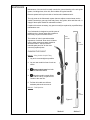
1
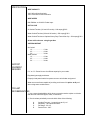
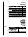
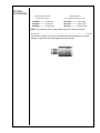
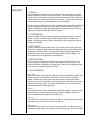
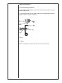
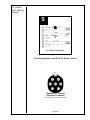
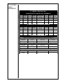
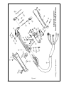
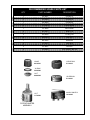
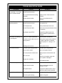
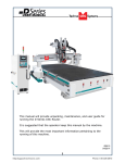
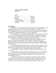
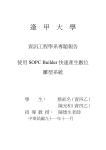
Product Description
Cobra III
M.K. Manual Part Number
091-0264
M.K. Form Number
NWSA Form Number
Effective with Serial Number
Voltage Rating
OWNERS
MANUAL
CTIII
550
35000
24 VDC
Printing/Revision Date
9/95
This manual applies
to the following
Torch Model Numbers
160-xxx
161-xxx
162-xxx
163-xxx
Cobramatic® Gooseneck Welding Torch
MK PRODUCTS, INC.
16882 ARMSTRONG AVE., IRVINE, CALIFORNIA
92714 TEL (714) 863-1234
FAX (714) 474-1428
SAFETY CONSIDERATIONS
ELECTRIC ARC WELDING EQUIPMENT
CAUTION : READ BEFORE ATTEMPTING INSTALLATION, OPERATION OR
MAINTENANCE OF THIS EQUIPMENT
1-1 INTRODUCTION
This equipment is intended for ultimate application by
commercial/industrial users and for operation by persons
trained and experienced in the use and maintenance of
welding equipment. Operation should not be undertaken
without adequate training in the use of such equipment.
Training is available from many public and private schools
or similar facilities.
Safe practices in the installation, operation and maintenance
of this equipment requires proper training in the art, a careful
study of the information provided with the equipment, and
the use of common sense. Rules for safe use are generally
provided by suppliers of welding power sources, compressed
gas suppliers, and electrode suppliers. Careful compliance
with these rules will promote safe use of this equipment.
The following Safety Rules cover some of the more generally
found situations. READ THEM CAREFULLY. In case of any
doubt, obtain qualified help before proceeding.
1-2 GENERAL PRECAUTIONS
A. Burn Prevention
ELECTRIC ARC WELDING PRODUCES HIGH INTENSITY
HEAT AND ULTRAVIOLET RADIANT ENERGY WHICH
MAY CAUSE SERIOUS AND PERMANENT EYE DAMAGE
AND WHICH MAY DAMAGE ANY EXPOSED SKIN AREAS.
Wear helmet with safety goggles or glasses with side
shields underneath, appropriate filter lenses or plates
(protected by clear cover glass). This is a must for welding
or cutting (and chipping) to protect the eyes from radiant
energy and flying metal. Replace cover glass when broken,
pitted, or spattered.
Medical first aid and eye treatment. First aid facilities and a
qualified first aid person should be available for each shift
unless medical facilities are close by for immediate treatment
of flash burns of the eyes and skin burns.
Wear protective clothing - leather (or asbestos) gauntlet
gloves, hat, and high safety-toe shoes. Button shirt collar
and pocket flaps, and wear cuffless trousers to avoid entry
of sparks and slag.
Avoid oily or greasy clothing. A spark may ignite them.
Flammable hair preparations should not be used by persons
intending to weld or cut.
Hot metal such as electrode stubs and work pieces should
never be handled without gloves.
Ear plugs should be worn when working on overhead or in
a confined space. A hard hat should be worn when others
work overhead.
B. Toxic Fume Prevention
Adequate ventilation. Severe discomfort, illness or death
can result from fumes, vapors, heat, or oxygen enrichment
or depletion that welding (or cutting) may produce. Prevent
them with adequate ventilation. NEVER ventilate with
oxygen.
Lead-, cadmium-, zinc-, mercury-, beryllium-bearing and
Cobra Gooseneck Owner's Manual - 8/96
similar materials, when welded or cut, may produce harmful
concentrations of toxic fumes. Adequate local exhaust
ventilation must be used, or each person in the area, as well as
the operator, must wear an air-supplied respirator. For beryllium,
both must be used.
Metals coated with or containing materials that emit toxic
fumes should not be heated unless coating is removed form
the work surface, the area is well ventilated, or the operator
wears an air-supplied respirator.
Work in a confined space only while it is being ventilated and,
if necessary, while wearing an air-supplied respirator.
Gas leaks in a confined space should be avoided. Leaked gas
in large quantities can change oxygen concentration
dangerously. Do not bring gas cylinders into a confined space.
Leaving confined space, shut OFF gas supply at source to
prevent possible accumulation of gases in the space if
downstream valves have been accidently opened or left open.
Check to be sure that the space is safe before reentering it.
Vapors from chlorinated solvents can be decomposed by the
heat of the arc (or flame) to form PHOSGENE, a highly toxic
gas, and other lung and eye irritating products. The ultraviolet
(radiant) energy of the arc can also decompose trichloroethylene
and perchloroethylene vapors to form phosgene. DO NOT
WELD or cut where solvent vapors can be drawn into the
welding or cutting atmosphere or where the radiant energy can
penetrate to atmospheres containing even minute amounts of
trichloroethylene or perchloroethylene.
C. Fire and Explosion Prevention
Causes of fire and explosion are: combustibles reached by the
arc, flame, flying sparks, hot slag, or heated material, misuse
of compressed gases and cylinders, and short circuits.
BE AWARE THAT flying sparks or falling slag can pass through
cracks, along pipes, through windows or doors, and through
wall or floor openings, out of sight of the goggled operator.
Sparks can fly many feet.
To prevent fires and explosion:
Keep equipment clean and operable, free of oil, grease, and (in
electrical parts) of metallic particles that can cause short
circuits.
If combustibles are in area, do NOT weld or cut. Move the work
if practicable, to an area free of combustibles. Avoid paint
spray rooms, dip tanks, storage areas, ventilators. If the work
cannot be moved, move combustibles at least 35 feet away,
out of reach of sparks and heat; or protect against ignition with
suitable and snug-fitting, fire-resistant covers or shields.
Walls touching combustibles on opposite sides should not be
welded on (or cut). Walls, ceilings, and floor near work should
be protected by heat-resistant covers or shields.
Fire watcher must be standing by with suitable fire extinguishing
equipment during and for some time after welding or cutting if:
1. Appreciable combustibles (including building construction)
are within 35 feet.
4. Combustibles adjacent to walls, ceilings, roofs, or metal
partitions can be ignited by radiant or conducted heat.
Hot work permit should be obtained before operation to
ensure supervisor’s approval that adequate precautions
have been taken.
After work is done, check that area is free of sparks, glowing
embers, and flames.
An empty container that held combustibles, or that can
produce flammable or toxic vapors when heated, must
never be welded on or cut, unless container has first been
cleaned in accordance with industry standards.
This includes: a thorough steam or caustic cleaning (or a
solvent of water washing, depending on the combustible’s
solubility), followed by purging and inerting with nitrogen or
carbon dioxide, and using protective equipment.
Water-filling just below working level may substitute for
inerting.
A container with unknown contents should be cleaned (see
paragraph above). Do NOT depend on sense of smell or
sight to determine if it is safe to weld or cut.
Hollow castings or containers must be vented before welding
or cutting. They can explode.
Explosive atmospheres. NEVER weld or cut where the air
may contain flammable dust, gas, or liquid vapors (such as
gasoline).
D. Compressed Gas Equipment
The safe handling of compressed gas equipment is detailed
in numerous industry publications. The following general
rules cover many of the most common situations.
1. Pressure Regulators
Regulator relief valve is designed to protect only the regulator
from overpressure; it is not intended to protect any
downstream equipment. Provide such protection with one
or more relief devices.
Never connect a regulator to a cylinder containing gas other
than that for which the regulator was designed.
Remove faulty regulator from service immediately for repair
(first close cylinder valve). The following symptoms indicate
a faulty regulator:
Leaks - if gas leaks externally.
Excessive Creep - if delivery pressure continues to rise with
downstream valve closed.
Faulty Gauge - if gauge pointer does not move off stop pin
when pressurized, nor returns to stop pin after pressure
release.
Repair. Do NOT attempt repair. Send faulty regulators for
repair to manufacturer’s designated repair center, where
special techniques and tools are used by trained personnel.
2. Cylinders
2.
Appreciable combustibles are further than 35 feet, but can
be ignited by sparks.
3. Openings (concealed or visible) in floors or walls within 35
feet may expose combustibles to sparks.
Cylinders must be handled carefully to prevent leaks and
damage to their walls, valves, or safety devices:
Avoid electrical circuit contact with cylinders including third
rails, electrical wires, or welding circuits. They can
produced short circuit arcs that may lead to a serious
accident. (See 1-3C)
ICC or DOT marking must be on each cylinder. It is an
assurance of safety when the cylinder is properly handled.
Identifying gas content. Use only cylinders with name of
gas marked on them; do not rely on color to identify gas
content. Notify supplier if unmarked. NEVER DEFACE
or alter name, number, or other markings on a cylinder.
It is illegal and hazardous.
Empties: Keep valves closed, replace caps securely;
mark MT; keep them separate from FULLS, and return
promptly.
Prohibited use. Never use a cylinder or its contents for
other than its intended use, NEVER as a support or roller.
Locate or secure cylinders so they cannot be knocked
over.
Passageways and work areas. Keep cylinders clear of
areas where they may be stuck.
Transporting cylinders. With a crane, use a secure
support such as a platform or cradle. Do NOT lift
cylinders off the ground by their valves or caps, or by
chains, slings, or magnets.
Do NOT expose cylinders to excessive heat, sparks,
slag, and flame, etc. that may cause rupture. Do not allow
contents to exceed 55 degrees C (130 degrees F.) Cool
with water spray where such exposure exists.
Protect cylinders, particularly valves from bumps, falls,
falling objects, and weather. Replace caps securely
when moving cylinders.
Stuck valve. Do NOT use a hammer or wrench to open
a cylinder valve that cannot be opened by hand. Notify
your supplier.
Mixing gases. NEVER try to mix any gases in a cylinder.
that the regulator label and cylinder marking agree, and that
the regulator inlet and cylinder outlet match. NEVER Connect
a regulator designed for a particular gas or gases to a cylinder
containing any other gas.
shoes. As necessary, use additional protective clothing
such as leather jacket or sleeves, flameproof apron, and
fire-resistant leggings. Avoid outer garments of untreated
cotton.
Tighten connections. When assembling threaded connections,
clean and smooth seats where necessary. Tighten. If
connection leaks, disassemble, clean, and retighten, using
properly fitting wrench.
Bare skin protection. Wear dark, substantial clothing.
Button collar to protect chest and neck, and button
pockets to prevent entry of sparks.
Adapters. Use a CGA adapter (available from your supplier)
between cylinder and regulator, if one is required. Use two
wrenches to tighten adapter marked RIGHT and LEFT HAND
threads.
2. Eye and Head Protection
Regulator outlet (or hose) connections may be identified by
right hand threads for oxygen and left hand threads (with
grooved hex on nut or shank) for fuel gas.
5. Pressurizing Steps:
Cylinder fittings should never be modified or exchanged.
Welding helmet or shield containing a filter plate shade
no. 12 or denser must be used when welding. Place over
face before striking arc.
Protect filter plate with a clear cover plate.
Drain regulator of residual gas through suitable vent before
opening cylinder (or manifold valve) by turning adjusting screw
in (clockwise). Draining prevents excessive compression heat
at high pressure seat by allowing seat to open on pressurization.
Leave adjusting screw engaged slightly on single-stage
regulators.
Stand to side of regulator while opening cylinder valve.
Open cylinder valve slowly so that regulator pressure increases
slowly. When gauge is pressurized (gauge reaches regulator
maximum) leave cylinder valve in following position: for oxygen
and inert gases, open fully to seal stem against possible leak;
for fuel gas, open to less than one turn to permit quick
emergency shut-off.
Use pressure charts (available from your supplier) for safe and
efficient recommended pressure settings on regulators.
Check for leaks on first pressurization and regularly thereafter.
Brush with soap solution. Bubbles indicate leaks. Clean off
soapy water after test; dried soap is combustible.
E. User Responsibilities
NEVER refill any cylinder.
Protect eyes from exposure to arc. Eyes may be damaged
by radiant energy when exposed to the electric arc, even
when not looking in the direction of the arc. Never look
at an electric arc without protection.
Cracked or broken helmet or shield should NOT be worn;
radiation can be passed through to cause burns.
Cracked, broken, or loose filter plates must be replaced
IMMEDIATELY. Replace clear cover plate when broken,
pitted, or spattered.
Flash goggles with side shields MUST be worn under the
helmet to give some protection to the eyes should the
helmet not be lowered over the face before an arc is
struck. Looking at an arc momentarily with unprotected
eyes (particularly a high intensity gas-shielded arc) can
cause a retinal burn that may leave a permanent dark
area in the field of vision.
3. Protection of Nearby Personnel
Enclose the welding area. For production welding, a
separate room or enclosed bay is best. In open areas,
surround the operation with low-reflective, noncombustible
screens or panels. Allow for free air circulation, particularly
at floor level.
Viewing the weld. Provide face shields for all persons
who will be looking directly at the weld.
Follow all Safety Rules.
Remove leaky or defective equipment from service immediately
for repair. Read and follow user manual instructions.
Others working in area. See that all persons are wearing
flash goggles.
Prohibited use. Never use hose other than that designed
for the specified gas. A general hose identification rule
is: red for fuel gas, green for oxygen, and black for inert
gases.
F. Leaving Equipment Unattended
Before starting to weld, make sure that screen flaps or
bay doors are closed.
Use ferrules or clamps designed for the hose (not ordinary
wire or other substitute) as a binding to connect hoses to
fittings.
G. Rope Staging-Support
3. Hose
No copper tubing splices.
fittings to splice hose.
Use only standard brass
Avoid long runs to prevent kinks and abuse. Suspend
hose off ground to keep it from being run over, stepped
on, or otherwise damaged.
Coil excess hose to prevent kinks and tangles.
Protect hose from damage by sharp edges, and by
sparks, slag, and open flame.
Examine hose regularly for leaks, wear, and loose
connections. Immerse pressured hose in water; bubbles
indicate leaks
Repair leaky or worn hose by cutting area out and
splicing. Do NOT use tape.
4. Proper Connections
Clean cylinder valve outlet of impurities that may clog
orifices and damage seats before connecting regulator.
Except for hydrogen, crack valve momentarily, pointing
outlet away from people and sources of ignition. Wipe
with a clean, lintless cloth.
Match regulator to cylinder. Before connecting, check
Cobra Gooseneck Owner's Manual - 8/96
Close gas supply at source and drain gas.
Rope staging-support should not be used for welding or cutting
operation; rope may burn.
1-3 ARC WELDING
Comply with precautions in 1-1, 1-2, and this section. Arc
Welding, properly done, is a safe process, but a careless
operator invites trouble. The equipment carries high currents
at significant voltages. The arc is very bright and hot. Sparks
fly, fumes rise, ultraviolet and infrared energy radiates,
weldments are hot, and compressed gases may be used. The
wise operator avoids unnecessary risks and protects himself
and others from accidents.
A. Burn Protection
B. Toxic Fume Prevention
Comply with precautions in 1-2B.
Generator engine exhaust must be vented to the outside
air. Carbon monoxide can kill.
C. Fire and Explosion Prevention
Comply with precautions in 1-2C.
Equipment’s rated capacity. Do not overload arc welding
equipment. It may overheat cables and cause a fire.
Loose cable connections may overheat or flash and
cause afire.
Never strike an arc on a cylinder or other pressure vessel.
It creates a brittle area that can cause a violent rupture or
lead to such a rupture later under rough handling.
Comply with precautions in 1-2.
The welding arc is intense and visibly bright. Its radiation can
damage eyes, penetrate lightweight clothing, reflect from lightcolored surfaces, and burn the skin and eyes. Skin burns
resemble acute sunburn; those from gas-shielded arcs are
more severe and painful. DON’T GET BURNED; COMPLY
WITH PRECAUTIONS.
1. Protective Clothing
Wear long-sleeve clothing in addition to gloves, hat, and
D. Compressed Gas Equipment
Comply with precautions in 1-2D.
E. Shock Prevention
Exposed electrically hot conductors or other bare metal
in the welding circuit, or in ungrounded, electrically-HOT
equipment can fatally shock a person whose body
becomes a conductor. DO NOT STAND, SIT, LIE, LEAN
ON, OR TOUCH a wet surface when welding without
suitable protection.
shut OFF all power, and remove line fuses (or lock or red-tag
switches) to prevent accidental turning ON of power. Disconnect
all cables from welding power source, and pull all 115 volts linecord plugs.
To protect against shock:
Do not open power circuit or change polarity while welding. If,
in an emergency, it must be disconnected, guard against
shock burns or flash from switch arcing.
Leaving equipment unattended. Always shut OFF, and
disconnect all power to equipment.
Keep body and clothing dry. Never work in damp area
without adequate insulation against electrical shock.
Stay on a dry duckboard, or rubber mat when dampness
or sweat cannot be avoided. Sweat, sea water, or
moisture between body and an electrically HOT part - or
grounded metal - reduces the body surface electrical
resistance, enabling dangerous and possibly lethal
currents to flow through the body.
1. Grounding the Equipment
When installing, connect the frames of each unit such as
welding power source, control, work table, and water
circulator to the building ground. Conductors must be
adequate to carry ground currents safely. Equipment
made electrically HOT by stray currents may shock,
possibly fatally. Do NOT GROUND to electrical conduit,
or to a pipe carrying ANY gas or a flammable liquid such
as oil or fuel.
Three-phase connection. Check phase requirement of
equipment before installing. If only three-phase power is
available, connect single-phase equipment to only two
wires of the three-phase line. Do NOT connect the
equipment ground lead to the third (live) wire, or the
equipment will become electrically HOT - a dangerous
condition that can shock, possibly fatally.
Before welding, check ground for continuity. Be sure
conductors are touching bare metal of equipment frames
at connections.
If a line cord with a ground lead is provided with the
equipment for connection to a switch box, connect the
ground lead to the grounded switch box. If a three-prong
plug is added for connection to a grounded mating
receptacle, the ground lead must be connected to the
ground prong only. If the line cord comes with a threeprong plug, connect to a grounded mating receptacle.
Never remove the ground prong from a plug, or use a
plug with a broken ground prong.
2. Connectors
Fully insulated lock-type connectors should be used to
join welding cable lengths.
3. Cables
Frequently inspect cables for wear, cracks, and damage.
IMMEDIATELY REPLACE those with excessively worn
or damaged insulation to avoid possibly lethal shock from
bared cable. Cables with damaged areas may be taped
to give resistance equivalent to original cable.
Keep cable dry, free of oil and grease, and protected from
hot metal and sparks.
4. Terminals and Other Exposed Parts
Terminals and other exposed parts of electrical units
should have insulating covers secured before operation.
5. Electrode Wire
Electrode wire becomes electrically HOT when the power
switch of gas metal-arc welding equipment is ON and
welding gun trigger is pressed. Keep hands and body
clear of wire and other HOT parts.
6. Safety Devices
Safety devices such as interlocks and circuit breakers
should not be disconnected or shunted out.
Before installation, inspection, or service of equipment,
Cobra Gooseneck Owner's Manual - 8/96
Power disconnect switch must be available near the welding
power source.
INTRODUCTION
Congratulations! You have just purchased the latest generation of the
popular Cobra System III Gooseneck Torch.
With the quest to be a Leader in Welding Technology this generation of Cobra
System III Gooseneck Torch is the best MK Products has ever developed.
Stronger gas and water tubes, motor and gearbox with enough torque and
speed to feed aluminum and flux core wires from .030 to 1/16, solid and hard
wires from .030 to .045. Matched up with any of MK’s Cobramatic wire feed
system is a combination that can not be beat.
This manual details the installation and operation of your Cobra System III
Gooseneck Torch. Properly installed, adjusted for your welding conditions, it
will be a reliable welding system producing consistently uniform welds.
Conduits for all MK torches (System III Gooseneck, Prince, and King) are
interchangeable. Some parts are interchangeable with existing Gooseneck
and Prince torches (contact tips, gas cups, drive and idler rolls). Consult
your owner’s manual for more information on your Cobra System III Gooseneck
torch.
Cobra Gooseneck Owner's Manual - 8/96
Page 26
SPECIFICATIONS
WIRE CAPACITY
.030-.045 solid and hard wire
.030-1/16 aluminum and cored wire
WIRE SPEED
800 IPM Max. at 120VAC Feeder Input
DUTY CYCLE
Air Cooled Torches (161 and 163 series) - 200 amps @ 50%
Water Cooled Torches (160 and 162 series) - 250 amps @ 50%
Water Cooled Torches w/ Optional Heavy Duty Finned Gas Cup - 300 amps @ 50%
All are at 25 volts max. using Argon Gas
SHIPPING WEIGHT
Air Cooled
15' .........................
25' .........................
50' .........................
Water Cooled
15' .........................
25' .........................
50' .........................
13 lbs.
18 lbs.
30 lbs.
15 lbs.
19 lbs.
32 lbs.
SUPPORT
EQUIPMENT
REQUIRED
C.V. or C.C. Power Source of sufficient capacity for your needs.
Regulated gas supply and hoses.
Properly sized power leads from power source to wire feeder and ground.
Water source and hose capable of providing a minimum of 1 qt/min. at 45 p.s.i.
when using water cooled torches.
COOLANT
RECOMMENDATIONS
1. Use a name-brand additive which does not contain reactive sulphur or chlorine
and does not react with copper, brass, or aluminum.
2. Check coolant periodically to remain within limits of the following:
A.
B.
C.
D.
Cobra Gooseneck Owner's Manual - 8/96
Coolant Flow rate - 1 quart/minute at 45 p.s.i.
Resistivity - 10K ohms/centimeter
Ph Range - 5.5-8.5
Particle Size - .005"
Page 1
ACTUAL SIZE
Spray Arc
Short Arc
CONTACT TIPS
CONTACT TIP SELECTOR GUIDE
WIRE SIZE
TIP I.D. **
ARC TYPE
LENGTH
PART NO.
.030" (0.8mm)
Spray Arc
1-1/2" (38mm)
621-0057
.030" (0.8mm)
Short Arc
1-3/4" (44mm)
621-0328
.036" (0.9mm)
Spray Arc
1-1/2" (38mm)
621-0325
.036" (0.9mm)
Short Arc
1-3/4" (44mm)
621-0326
.040" (1.0mm)
Spray Arc
1-1/2" (38mm)
621-0076
.040" (1.0mm)
Short Arc
1-3/4" (44mm)
621-0077
.044" (1.1mm)
Spray Arc
1-1/2" (38mm)
621-0001
.044" (1.1mm)
Short Arc
1-3/4" (44mm)
621-0002
.045" (1.2mm)
.053" (1.3mm)
Spray Arc
1-1/2" (38mm)
621-0327
.045" (1.2mm)
or
.052" (1.3mm)
*.060" (1.5mm)
Spray Arc
1-1/2" (38mm)
621-0003
.060" (1.5mm)
Short Arc
1-3/4" (44mm)
621-0286
1/16" (1.6mm)
.075" (1.9mm)
Spray Arc
1-1/2" (38mm)
621-0075
.085" (2.1mm)
Spray Arc
1-1/2" (38mm)
621-0153
.085" (2.1mm)
Short Arc
1-3/4" (44mm)
621-0154
.023" (0.6mm)
.030" (0.8mm)
.030" (0.8mm)
or
.035" (0.9mm)
.035" (0.9mm)
1/16" (1.6mm)
contact.tbl
* Standard - Furnished with torch. ** All tips stamped with tip I.D.
NOTE: As a rule of thumb, use the smaller I.D. tip for steel, stainless steel and the 5000 series aluminum. Softer alloys such as the 1000 and 4000
series aluminum require more clearance and, therefore, use a larger I.D. tip.
Standard Cup
GAS CUPS
STANDARD GAS CUPS
SIZE
I.D.
PART NO.
5
1/4" (6.4mm)
621-0079
6
3/8" (9.5mm)
001-0137
*8
1/2" (12.7mm)
10
5/8" (15.8mm)
HEAVY-DUTY GAS CUPS
SIZE
I.D.
PART NO.
001-0138
8
1/2" (12.7mm)
621-0366
001-0139
10
5/8" (15.8mm)
621-0367
*Standard - Furnished with torch
Cobra Gooseneck Owner's Manual - 8/96
Page 2
TORCH LINERS
BARREL
LINER MATERIAL
WIRE TYPE USED
PART NO.
Straight*
Green Teflon
All
615-0316
Curved & Long Straight
Green Teflon
Aluminum
615-0317
Curved & Long Straight
Spiral Steel
Steel / Cored
615-0318
Spool Kit liner
Black Teflon
All
615-0319
Straight
HD White Teflon
All (.045max.)
615-0325
Curved & Long Straight
HD White Teflon
Aluminum (3/64max.)
615-0326
*Standard - Furnished with torch
Bulk green teflon liner material P/N 615-0054 - Bulk HD white teflon liner material (.023-.045) P/N 615-0209 - Order bulk material by
the foot.
OPTIONAL KITS
Insulated Knurled Drive Roll Kit ............................................................................................ 005-0118
For .030" through 1/16" dia. wire. Includes insulated drive roll P/N 511-0068 and
idler roll assy. P/N 511-0074.
Insulated Groove Drive Roll Kit ............................................................................................. 005-0244
For .030" (0.8mm) dia. aluminum wire.
Includes and insulated drive roll P/N 511-0089 and idler roll assy. P/N 003-1870.
Insulated Groove Drive Roll Kit ............................................................................................. 005-0245
For .035" (0.9mm) dia. aluminum wire.
Includes insulated drive roll P/N 511-0090 and idler roll assy. P/N 003-1870.
Insulated Groove Drive Roll Kit ............................................................................................. 005-0246
For .040" (1.0mm)dia. aluminum wire.
Includes insulated drive roll P/N 511-0091 and idler roll assy. P/N 003-1870.
Insulated Groove Drive Roll Kit ............................................................................................. 005-0247
For .045" (1.2mm) dia. aluminum wire.
Includes insulated drive roll P/N 511-0092 and idler roll assy. P/N 003-1870.
Insulated Groove Drive Roll Kit ............................................................................................. 005-0248
For .062" (1.6mm) dia. aluminum wire.
Includes insulated drive roll P/N 511-0093 and idler roll assy. P/N 003-1870.
Handle Kit - System III torch only ......................................................................................... 005-0255
Includes right and left handles, trigger, pot nut, and knob and related hardware.
NOTE: Insulated drive roll kits are used to prevent preheating of the wire which may
soften it and clog the liner. This picking up of current at the drive rolls rather than at
the contact tip is usually not a problem usless using too large of a contact tip or
excessively oxidized aluminum wire.
Cobra Gooseneck Owner's Manual - 8/96
Page 3
OPTIONAL
ACCESSORIES
Flat Spiral Steel Conduit
for steel & cored wire.
615-0208 ............ 15 ft./4.5m
615-0216 ............ 25 ft./7.6m
615-0218 ............ 50 ft./15.0m
StandardConduit
with additional protective cover.
001-0774 .............. 15 ft./4.5m
001-0775 .............. 25 ft./7.6m
001-0777 .............. 50 ft./15.0m
NOTE: The protective cover is used to help protect the conduit from burns.
Tip Extender ............................................................................................................................ 621-0017
Tip extender is used if torch cup or tip threads have been damaged or to prevent
damage. Longer liners are required when using tip extender.
Cobra Gooseneck Owner's Manual - 8/96
Page 4
OPERATION
1. GENERAL
The patented Cobra Gooseneck Torch maintains a constant, steady, uniform feed
speed, regardless of curved or looped wire conduit. The constant push exerted by
the slave motor in the cabinet, combined with the pull of the torch motor, causes the
wire to literally float friction-free through the wire conduit. The 24 volt DC torch motor
is controlled by a three (3) turn potentiometer in the torch handle.
The torch trigger is designed so that when it is partially depressed, gas flow starts via
the valve located in the torch body, prior to ignition of the arc. When the trigger is
partially released after welding (extinguishing the arc), gas flow continues until the
trigger is fully released; built-in pre and post gas flow.
2. POTENTIOMETER
The pot is located on the left hand side of the torch and provides three (3) turns of
rotation. A spacer is placed on the pot shaft before the pot is inserted into the
handle. A special pot nut and O-Ring provides drag on the knob and also secures
the pot to the handles.
3. MICRO SWITCH
The micro switch is wired “Normally Open” and secured to the torch block with two
(2) screws. An insulator between the torch block and micro switch prevents accidental shorting of the switch leads. The trigger pin reaches through the handle and
activates the micro switch just before the trigger bottoms out on the handle. The
micro switch lever may be adjusted to accomplish this.
4. MOTOR GEAR BOX
A 19.5:1 24VDC motor gear box is used on this version of the Gooseneck Torch.
The motor gear box attaches to the angle head with three (3) Allen screws. The
torch serial number is stamped on the angle head. There are no spare parts for the
motor gear box; it must be replaced as a whole.
5. LEAD ASSEMBLIES
Power Cable
Water-cooled torches use a bare #4 AWG power cable housed inside a flexible hose.
The torch fitting is screwed into the back of the torch block using a conductive
sealant. Because of the small cable used, these torches must be water-cooled.
Ultraflex torches, on the other hand, use a #2 AWG power cable which is secured to
the torch in the same manner. The power cable fitting on the end connects to the
power block inside the Cobramatic feeder.
Conduit
The Cobra Gooseneck comes standard with a teflon lined conduit. The torch end is
secured with a set screw accessable through a hole in the handles. Spiral steel
liners are available when using hard and cored wires.
Gas Hose
The gas hose is crimped to the inlet tube with a ferrule. The gas inlet tube is located
in the lower left of the torch when viewed from the rear.
Water-In Hose
The Water-In Hose is crimped to the inlet tube with a ferrule. The Water-In tube is
located in the upper right of the torch when viewed from the rear. Air cooled torches
Cobra Gooseneck Owner's Manual - 8/96
Page 5
do not have a Water-In Hose.
Electric Cable
A seven conductor control cable is used on the Gooseneck Torch. The torch end of
the control cable is secured to the back of the torch with a cable clamp and the wires
are soldered to the motor, pot, and micro switch. The cabinet end has a seven pin
“S” or “W” clocked Amphenol connector. See schematic for wiring information.
6. DRIVE AND IDLER ROLLS
A.
General
The Gooseneck torch comes standard with knurled drive rolls which will handle wire
diameters from .030-1/16 inch. Optional V-groove drive rolls are also available for
feeding aluminum wire if desired (see Optional Kits).
Drive roll tension is accomplished by means of a pressure-adjusting screw located
on the left hand side of the torch. Proper tension is achieved when wire does not slip
if a small amount of pressure is added to the wire as it exits the tip.
NOTE: Over-tightening of the drive rolls will cause excessive knurling and/or deformation of the wire.
B.
Drive Roll Installation/Removal
1. Remove right handle.
2. Rotate drive roll by jogging drive motor with trigger switch or with finger tips until
slots line up.
3. Hold the drive roll with 3/8" open-end wrench.
Figure 1
4. Insert a slot type screwdriver into the slot on motor shaft, and turn screwdriver
CCW (left hand thread).
5. Install new drive roll on motor shaft using left hand thread. Drive roll will selfCobra Gooseneck Owner's Manual - 8/96
Page 6
tighten when feeding wire.
C. Idler Roll Installation and Removal
1. Using a slot type screwdriver, loosen idler screw, taking care not to lose lock
washer under idler roll.
2. Insert new idler roll and lock washer onto screw, insuring that idler groove is
toward top and lock washer is beneath.
Figure 2
3. Tighten.
NOTE: Lock washer must be under idler roll or it will not turn freely.
Cobra Gooseneck Owner's Manual - 8/96
Page 7
"W" CLOCKED
TORCH WIRING
DIAGRAM
W
"W" Clocked Torch Wiring
This wiring applies to all 162 & 163 Series Torches
KEY
INDICATOR
New "W" Clocked
Amphenol Connector
Viewed from the front of connector
Figure 3
Cobra Gooseneck Owner's Manual - 8/96
Page 8
"S" clocked
Torch Hook-up
Diagram
S
"S" Clocked Torch Wiring
This wiring applies to all 160 & 161 Series Torches
KEY
INDICATOR
Standard "S" Clocked
Amphenol Connector
Viewed from the front of connector
Figure 6
Cobra Gooseneck Owner's Manual - 8/96
Page 9
"W" CLOCKED
CABLE
ASSEMBLIES
"W" SERIES TORCHES ONLY
162 SERIES WATER COOLED CABLE ASSEMBLIES
Length
Complete
Cable Assy
Conduit
#4 Water/
Power
Cable
Electrical Cable
7 pin "W"
Clocked
Gas
Hose
Water In
Hose
Boot
15'
001-1196
615-0007
001-2521
001-3787
001-0537
001-0529
551-0272
25'
001-1197
615-0008
001-2524
001-3788
001-0538
001-0530
551-0273
50'
001-1199
615-0068
843-0338
001-3790
001-0665
001-0667
551-0293
163 SERIES ULTRA FLEX CABLE ASSEMBLIES
Length
Complete
Cable Assy
Conduit
#2 Power
Cable
Electrical Cable
7 pin "W"
Clocked
Gas
Hose
Boot
15'
001-1143
615-0007
001-2527
001-3787
001-0537
551-0274
25'
001-1144
615-0008
001-2528
001-3788
001-0538
551-0275
50'
001-1145
615-0068
001-1042
001-3790
001-0665
551-0277
CABLE FITTINGS & FERRULES
Power Cable Fittings for #4 Water-Cooled Torches (162 series)
Component
Torch End
Cabinet End
Ferrule #650
Part No.
003-0590
003-1327
469-0002
Power Cable Fittings for Ultra-Flex Torches (163 series)
Component
Torch End
Cabinet End
Part No.
431-1128
003-1328
Gas Hose & Water In Hose Ferrules (all Torches)
Component
Ferrule #400
Cabinet End Nut & Nipple
Part No.
469-0161
753-0464
See page xx for listings on "S" clocked Torches
MODEL NUMBER
REFERENCE
CHART
MODEL
SERIES
DESCRIPTION
CONNECTOR
CLOCKING
WIRE IPM
CABLE
TYPE
160-xxx
Cobra Gooseneck
S
800
Water-Cooled
161-xxx
Cobra Gooseneck
S
800
Air-Cooled
162-xxx
Cobra Gooseneck
W
800
Water-Cooled
163-xxx
Cobra Gooseneck
W
800
Air-Cooled
Cobra Gooseneck Owner's Manual - 8/96
Page 10
"S" CLOCKED
CABLE
ASSEMBLIES
"S" SERIES TORCHES ONLY
160 SERIES WATER COOLED CABLE ASSEMBLIES
Length
Complete
Cable
Assy
Conduit
#4 Water/
Power
Cable
Electrical Cable
7 pin "S"
Clocked
Gas Hose
Water-In
Hose
Boot
15'
001-1009
615-0007
001-2521
001-3794
001-0537
001-0529
551-0272
25'
001-1010
615-0008
001-2524
001-3795
001-0538
001-0530
551-0273
50'
001-1012
615-0068
843-0338
001-3797
001-0665
001-0667
551-0293
161 SERIES ULTRA FLEX CABLE ASSEMBLIES
Length
Complete
Cable
Assy
Conduit
#2 Power
Cable
Electrical Cable
7 pin "S"
Clocked
Gas Hose
Boot
15'
001-1025
615-0007
001-2527
001-3794
001-0537
551-0274
25'
001-1026
615-0008
001-2528
001-3795
001-0538
551-0275
50'
001-1043
615-0068
001-1042
001-3797
001-0665
551-0277
CABLE FITTINGS & FERRULES
Power Cable Fittings for #4 Water-Cooled Torches (160 series)
Component
Torch End
Cabinet End
Ferrule #650
Part No.
003-0590
003-1327
469-0002
Power Cable Fittings for Ultra-Flex Torches (161 series)
Component
Torch End
Cabinet End
Part No.
431-1128
003-1328
Gas Hose & Water In Hose Ferrules (all Torches)
Component
Ferrule #400
Cabinet end Nut & Nipple
Part No.
469-0161
753-0464
Cobra Gooseneck Owner's Manual - 8/96
Page 11
Figure 4
Cobra Gooseneck Owner's Manual - 8/96
Page 12
NOTE
These are optional items.
Cobramatic System III
Gooseneck Torch Exploded View
PARTS LIST GOOSENECK
TORCH
ITEM
PART NO.
QTY
1
401-0521
1
2
303-0540
3
DESCRIPTION
ITEM
PART NO.
QTY
DESCRIPTION
Knob
28
333-0082
1
Washer Lock #10 Med.
1
"O" Ring
29
511-0001
1
Idler Roll
449-0542
1
Nut, Pot
30
325-0206
1
Screw P.H. #10-24 x 3/8 LG
5
117-0520
1
Potentiomenter
31
421-3106
1
Dowel Pin 1/8 dia. x 3/4 LG
6
328-0015
1
Screw,Soc.HD.Cap #6-32 x 3/4
32
413-0017
1
Idler Arm
7
437-0202
1
Handle, Left Side
33
419-0020
1
Spring Roll Pressure
8
333-0039
2
Lock Washer #2 Int. Star
34
431-0015
1
Torch, Adjusting Screw
9
325-0025
2
Screw, P.H. #2-56 x 3/8 LG
35
See Table
1
Lead Assembly
10
161-0002
1
Micro Switch
36
003-0302
1
Lever-SwitchActuator
11
261-0069
1
Insulator
37
421-0018
1
Dowel Pin 3/32 Dia. x 7/8 LG
12
001-1202
1
Front Body Assy.
38
437-0201
1
Handle, Right Side
13
321-0001
2
Set Screw, #4-40 x 1/8LG
39
328-0013
1
Screw,Cap Soc.HD #6-32 x 1/2
14
431-0743
1
Front Wire Guide
40
328-0002
1
Screw,Cap Soc.HD #4-40 x 3/8
15
431-0115
1
Rear Wire Guide
41
328-0014
1
Screw,Cap Soc.HD #6-32 x 5/8
16
411-0159
1
Cable Clamp
42
615-0055
1
Teflon Liner
17
328-0216
1
Screw Soc.HD Cap#3-48 x 3/16
43
621-0003
1
ContactTip
18
001-0562
1
Gas Valve Assy.
44
001-0138
1
Gas Cup #8
19
419-0742
1
Spring
45
615-0284
1
Spiral Liner
20
001-0740
1
Valve Stem Assy. *
46
621-0017
1
Tip Extension
21
001-0553
1
GasValve Seat Assy.
47
615-0058
1
Long Teflon Liner
22
001-3662
1
Motor & Gear Box Assy. (800ipm)**
48
615-0057
1
Long Spiral Liner
23
211-0058
1
Motor - Pittman (19.5:1) (800ipm)**
49
321-1074
1
Screw, set. modified
24
003-1300
1
Gear Box Assy.
50
321-0083
1
Screw, set. 1/4 - 20 x 3/8
25
328-0003
3
Screw Cap Soc.HD #4-40 x 3/8
51
na
26
511-0016
1
Drive Roll
52
333-0003
3
Lock Washer
27
321-0080
1
Screw, Set.1/4 - 20 x 3/16
*NOTE: If feeder is equipped with gas solenoid, modified gas valve stem P/N 431-1080 must be installed in torch.
**NOTE: The following items are for the optional High Speed Torch.
22 001-3673 Motor & Gear Box (1000 ipm) Optional High Speed
23 211-0064 Motor - Pittman (10:1) (1000 ipm) Optional High Speed
(Motor leads must be reversed on the high speed motor)
Cobra Gooseneck Owner's Manual - 8/96
Page 13
RECOMMENDED SPARE PARTS LIST
QTY
PART NUMBER
DESCRIPTION
1
615-0007
Conduit 15'
1
615-0008
Conduit 25'
1
615-0068
Conduit 50'
1
117-0520
Potentiometer
1
161-0002
Micro Switch
3
401-0521
Knob, Pot
2
303-0540
'O' Ring, Pot
2
449-0542
Nut, Pot
1
005-0202
Handle Kit
2
511-0016
Drive Roll
2
511-0001
Idler Roll
2
333-0082
Lock Washer, Idler roll
KNOB
DRIVE ROLL
401-0521
511-0016
'O' RING
303-0540
NUT
449-0542
IDLER ROLL
511-0001
POT
117-0520
MICRO SWITCH
161-0002
POTENTIOMETER
ASSEMBLY
Cobra Gooseneck Owner's Manual - 8/96
Page 14
TROUBLESHOOTING GUIDE
TROUBLE
CAUSE
No wire feed at torch, feeder 115 VAC Control fuse in
not operating, i.e. no slave
feeder/Control box blown.
motor or brake solenoid.
Micro-switch defective/not being
activated.
Broken electrical cable.
No wire feed at torch, feeder 24 VAC Control fuse in
operating properly
feeder/Control box blown.
REMEDY
Replace fuse.
Replace switch. Check switch for
operation
Check micro-switch wires for
continuity.
Check motor leads for shorts;
then replace fuse.
Bad Potentiometer.
Check potentiometer with meter
Broken Electrical Cable.
Check motor and potentiometer wires
for continuity.
Bad Speed control/PCB.
See specific cabinet/control box
owners manual for speed control
operation.
Wire feeds, but welding wire Loose or no cable connections.
Check all power connections.
is not energized.
Contactor control cable loose or in Check power supply owners manual
wrong position.
for location and type of contactor
signal required, i.e., closing or 115
VAC.
Wire feeds erratically.
Welding power source.
Check power source.
Excessive spool drag pressure.
Decrease spool drag pressure.
Dirty or worn conduit.
Blow out or replace conduit.
Incorrect pressure on drive rolls.
Adjust pressure at both feeder and
torch.
Idler roll stuck.
Check for lock washer under idler
roll, or replace if damaged.
Wrong size contact tip.
See Contact tip table.
Wire feeds one speed only.
Bad potentiometer.
Check with meter.
Broken electrical cable.
Check potentiometer wires for
continuity or short.
Bad speed control.
See specific cabinet/control owners
manual for speed control operation.
Wire walks out of drive rolls. Idler roll upside-down.
Rear wire guide missing.
Place groove in idler roll toward top.
Replace wire guide
trouble.tbl
Cobra Gooseneck Owner's Manual - 8/96
Page 15
TROUBLESHOOTING
Regardless of which torch or feeder used, all M.K. Products’ push-pull guns operate
on the same principle. The 115 VAC slave motor in the feeder runs at a fast, constant speed, but has very low torque. It is always trying to feed more wire than the
torch motor wants, and when the motor gets all it wants, it slows the slave motor,
preventing a bird’s nest. Because of the low torque produced by the slave motor, a
brake system is used to prevent wire overrun rather than tension. The drag adjustment in the spindle is used simply to keep the wire slightly taut, so it will not pull off
the spool while feeding wire.
The high torque 24 VDC torch motor is controlled by a solid state speed control and
a pot located in the torch. The torch motor, potentiometer, and micro switch are
connected to the cabinet/control box via a control cable and Amphenol. If this cable
becomes damaged, a variety of symptoms can occur, depending on which wire(s)
break. To test, check each wire for continuity and shorts.
Remember, the micro switch in the torch activates both the 115 VAC and 24 V
circuits in the cabinet. Therefore, if the slave motor and brake solenoid operate, but
the torch does not, look more toward the 24 V circuits, speed control, control cable,
or the torch motor. If nothing operates, look more toward the 115 VAC input, micro
switch leads, or micro switch.
TESTING THE TORCH
A. Motor Check
1. Remove the torch connector from the cabinet.
2. Using the torch Amphenol, check the resistance across pins “A” and “B” (motor
leads). The resistance across the motor should be between 5-10 ohms.
3. If an open circuit or short exist, check the motor leads and motor independently.
B. Testing the Potentiometer - “W” Clocked
1. Using the torch Amphenol, check the resistance across pin “D” (wiper) and pin
“C”. The resistance should vary from 0 - 5K ohms.
2. Check the resistance across pin “D” (wiper) and pin “G”. The resistance should
vary from 5K - 0 ohms.
C. Testing the Potentiometer - “S” Clocked
1. Using the torch Amphenol, check the resistance across pin “D” (wiper) and pin
“C”. The resistance should vary from 0 - 5K ohms.
2. Check the resistance across pin “D” (wiper) and pin “A”. The resistance should
vary from 5K - 0 ohms.
D. Testing the Micro Switch
1. Using the torch Amphenol, check for continuity across pins “E” and “F” when
the trigger is pressed.
Cobra Gooseneck Owner's Manual - 8/96
Page 16
MAINTENANCE
Maintenance of the torch will normally consist of a general cleaning of the wire guide
system, including tubes, drive rolls, and conduits at regular intervals.
Remove spatter build-up from inside of nozzles with a hardwood stick.
The only parts on the Cobramatic system that are subject to normal wear are the
conduit, contact tips, gas cups, front body liners, wire guides, drive and idler rolls. A
supply of these parts should be maintained on hand.
If repairs do become necessary, any part can easily be replaced by a qualified shop
maintenance man.
Your Cobramatic is designed to provide years of
reliable service. Normal wear and component
failure may require occasional service.
New
Conduit
The number of units in operation and the
importance of minimal “down time” will determine to what extent spare parts should be
stocked on hand. See the "Recommended spare parts list" for the most
commonly replaced parts.
New
Conduit
CHANGING THE CONDUIT
Method 1 - Using Conduit Coupler Fitting
1. Lay torch out as straight as possible.
2. Lay out new conduit in front of torch as
shown.
3.
Remove spiral wrap from both
ends of cable assemblies.
4.
Using the conduit coupler fitting,
(MK P/N 757-0012), couple the old
conduit to the new one.
5. Pull the old conduit out while an
assistant pushes the new one in.
Method 2 - Field Expedient
Old
Conduit
Figure 5
Method 1
Cobra Gooseneck Owner's Manual - 8/96
Method 2
Page 17
1.
Lay torch out as straight as possible.
2.
Lay out new conduit in front of torch as shown.
3.
Remove spiral wrap from both ends of cable assemblies.
4.
Using .045 hard wire, run it through the old and the new conduit and bend
wire over at both ends and tape secure.
5.
Pull the old conduit out while an assistant pushes the new one in.
Cobra Gooseneck Owner's Manual - 8/96
Page 18
SN
AKESKIN CABLE CO
VER
SNAKESKIN
COVER
IN ORDER TO PROVIDE BETTER FIELD SERVICEABILITY
WE HAVE REPLACED OUR CABLE COVERS WITH A NEW COVER
CALLED THE "SNAKESKIN".
A "Snakeskin" is a flexible, fire-resistant nylon cable cover with a flap protecting the zipper
which is used as a field replacement for COBRA, KING and PRINCE Mig torches. The MK
"Snakeskin" is the only cable cover with a protective flap over the zipper, making it an ideal
cover for Mig Torches. This cover is reusable reducing future replacement costs. The old
rubber boot was difficult to remove and replace in the field.
Features:
z
The zipper will not conduct electric current.
z
The zipper is covered with fabric to protect it from the welding spatter!
z
Sturdy, yet light weight fabric allows for continued easy flexing of the lead assy.
Use the chart below to order your new cover. You can cross reference to the new number
using either the old rubber boot part number or simply by cable lenghth.
Rubber Boot P/N
551-0272 (0274)
551-0273 (0275)
551-0293 (0277)
Cobra Gooseneck Owner's Manual - 8/96
Snakeskin P/N
931-0110
931-0122
931-0122 (2 REQ.)
Cable Length
15.0 ft
25.0 ft
50.0 ft
Page 19
Effective February 15, 1995
This warranty supersedes all previous MK Products warranties and is
exclusive, with no other guarantees or warranties expressed or implied.
LIMITED WARRANTY - MK Products,Inc.,Irvine,California
warrants that all new and unused equipment furnished by MK
Products is free from defect in workmanship and material as of the
time and place of delivery by MK Products. No warranty is made
by MK Products with respect to trade accessories or other items
manufactured by others. Such trade accessories and other items
are sold subject to the warranties of their respective manufacturers,
if any.
MK Products’ warranty does not apply to components having
normal useful life of less than one (1) year, such as relay points,
wire conduit, tungsten, and welding torch parts that come in
contact with the welding wire, including nozzles, nozzle insulators,
and contact tips where failure does not result from defect in
workmanship or material.
In the case of MK Products’ breach of warranty or any other duty
with respect to the quality of any goods, the exclusive remedies
therefore shall be at MK Products’ option: (1) repair; (2) replacement;
(3) where authorized in writing by MK Products, the reasonable
cost of repair or replacement at our Irvine, California plant; or (4)
payment of or credit for the purchase price (less reasonable
depreciation based upon actual use) upon return of the goods at
customer’s risk and expense. Upon receipt of notice of apparent
defect or failure, MK Products shall instruct the claimant on the
warranty claim procedures to be followed.
As a matter of general policy only, MK Products may honor an
original user’s warranty claims on warranted equipment in the
event of failure resulting from a defect within the following periods
from the date of delivery of equipment to the original user:
1.
2.
3.
4.
5.
Torches and Weldheads ........................................ 1 year
All Other Equipment ............................................. 2 years
Mechanical & Electro-Mechanical Components .. 1 year
Electronic Assemblies and Sub-Assemblies ..... 2 years
Repairs ................................................................... 90 days
MK PRODUCTS, INC.
16882 ARMSTRONG AVENUE
IRVINE, CA 92714
TEL (714) 863-1234
FAX (714) 474-1428
Classification of any item into the foregoing categories shall be at
the sole descretion of MK Products. Notification of any failure must
be made in writing within 30 days of such failure.
A copy of the invoice showing the date of sale, must accompany
products returned for warranty repair or replacement.
All equipment returned to MK Products for service must be
properly packaged to guard against damage from shipping, MK
Products will not be responsible for any damages resulting from
shipping.
Normal surface transportation charges (both ways) for products
returned for warranty repair or replacement will be borne by MK
Products, except for products sold for foreign markets.
ANY EXPRESS WARRANTY NOT PROVIDED HEREIN AND
ANY
IMPLIED
WARRANTY,
GUARANTY,
OR
REPRESENTATION AS TO PERFORMANCE, AND ANY
REMEDY FOR BREACH OF CONTRACT WHICH, BUT FOR
THIS PROVISION, MIGHT ARISE BY IMPLICATION,
OPERATION OF LAW, CUSTOM OF TRADE, OR COURSE OF
DEALING, INCLUDING ANY IMPLIED WARRANTY OF
MERCHANTABILITY OR OF FITNESS FOR PARTICULAR
PURPOSE, WITH RESPECT TO ANY AND ALL EQUIPMENT
FURNISHED BY MK PRODUCTS, IS EXCLUDED AND
DISCLAIMED BY MK PRODUCTS.
EXCEPT AS EXPRESSLY PROVIDED BY MK PRODUCTS IN
WRITING, MK PRODUCTS ARE INTENDED FOR ULTIMATE
PURCHASE BY COMMERCIAL/INDUSTRIAL USERS AND FOR
OPERATION BY PERSONS TRAINED AND EXPERIENCED IN
THE USE AND MAINTENANCE OF WELDING EQUIPMENT
AND NOT FOR CONSUMERS OR CONSUMER USE. MK
PRODUCTS WARRANTIES DO NOT EXTEND TO, AND NO RESELLER IS AUTHORIZED TO EXTEND MK PRODUCTS’
WARRANTIES TO ANY CONSUMER.
FORM : LW-6
DATE : February 1995
M.K. PRODUCTS, INC.
16882 ARMSTRONG AVE.
IRVINE, CALIFORNIA 92714
TEL (714) 863-1234 FAX (714) 474-1428
M.K. Part Number 091-0264
Printed in the U.S.A.