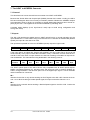
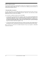
1
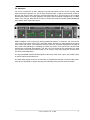
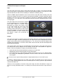
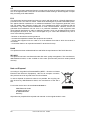
User's Guide
ADI-4 DD
SyncAlign
TM
TM
SyncCheck
Intelligent Clock Control
TM
TM
SteadyClock
Hi-Precision 24 Bit / 96 kHz
AES / ADAT Dual Format Converter
8-Channels ADAT® optical from / to AES/EBU Interface
AES-3
24 Bit Interface
Contents
1
2
3
4
Introduction ........................................................................................................3
Supplied Contents .............................................................................................3
Brief Description and Characteristics..............................................................3
Technical Specifications ...................................................................................4
4.1 Inputs...............................................................................................................4
4.2 Outputs............................................................................................................5
5
First Usage
5.1
Quick Start ......................................................................................................6
5.2
Operation ........................................................................................................7
6
The AES to ADAT Converter
6.1
General ...........................................................................................................8
6.2
Inputs...............................................................................................................8
6.3
Input State Display ..........................................................................................9
6.4
Outputs ADAT Optical.....................................................................................9
7
The ADAT to AES/EBU Converter
7.1
General .........................................................................................................10
7.2
Inputs.............................................................................................................10
7.3
Input State Display ........................................................................................11
7.4
Outputs AES/EBU .........................................................................................11
7.5
Double Wire Conversion ...............................................................................12
8
Clock Section
8.1
Clock Configuration.......................................................................................13
8.2
Lock, SyncCheck and SyncAlign ..................................................................13
8.3
Word Clock Input and Output........................................................................14
9
Word Clock
9.1
Operation and Technical Background ..........................................................15
9.2
Cabling and Termination...............................................................................16
10
Conversion Modes and Notes
10.1
8-channel AES to ADAT Converter (96 kHz) .............................................17
10.2
8-channel AES to 2 x ADAT Splitter (48 kHz) ............................................17
10.3
2-channel AES to 8-channel ADAT Splitter (96 kHz) .................................17
10.4
2-channel AES to 8-channel AES Splitter (96 kHz) ...................................17
10.5
4-channel AES Double Wire to AES Single Wire Converter (96 kHz) .......17
10.6
4-channel AES Single Wire to AES Double Wire Converter (96 kHz) .......18
10.7
8-channel ADAT to AES Converter (96 kHz) .............................................18
10.8
8-channel ADAT to 2 x ADAT Splitter (48 kHz)..........................................18
11
Technical Background
11.1
DS – Double Speed....................................................................................19
11.2
AES/EBU – SPDIF .....................................................................................20
12
Controls and Connectors ................................................................................21
13
Connector Pinouts ...........................................................................................22
14
Block Diagram ..................................................................................................24
15
Warranty............................................................................................................25
16
Appendix ...........................................................................................................25
2
User's Guide ADI-4 DD © RME
1. Introduction
With the ADI-8 DD you have an incredibly compact and flexible digital interface to your supply.
What at first looks like a simple AES/ADAT format converter, turns out to be a universal problem
solver at a closer look. From small project studios to broadcast and television, the ADI-4 DD is
the perfect link between the formats mostly used today.
As a consequent continuation of RME's world-wide successful ADI-8 series, the 4-DD also contains elaborate technology and the latest integrated circuits, delivering 8 full channels in 24 bit
and 96 kHz. The ADI-4 DD is a uniquely powerful and high-quality device, which will excite you
even after many years of operation.
2. Package Contents
Please check that your ADI-4 DD package contains each of the following:
• ADI-4 DD
• Quick Info
• Power supply 12 V / 1.25 A and power cord
3. Brief Description and Characteristics
The ADI-4 DD consists of two 8-channel digital format converters in reference quality, in a halfrack space enclosure with 1 unit height. The compact device has numerous extraordinary features like Intelligent Clock Control (ICC), SyncCheck®, SyncAlign®, Bitclock PLL, SteadyClock,
active jitter suppression and patchbay functionality.
All of the ADI-4 DD's I/Os support 96 kHz/24 bit. As ADAT optical is restricted to 48kHz, in DS
mode (Double Speed) two channels are being used for the transmission of one channel's data.
The Sample Split algorithm used is also implemented in RME's Hammerfall and Hammerfall
DSP. Thus the ADI-4 DD also serves as an ideal AES/EBU frontend for these interface cards,
on both Mac and PC.
The format conversion between AES/EBU and ADAT operates in both directions at the same
time. LEDs of different colours show the present state of incoming and outgoing signals and of
the internal processing in a clear way.
The unique Intelligent Clock Control (ICC) allows for a flexible use with external word clock or
the digital input signals. These options being available for both directions are intelligently coupled in a way typical for RME and easy to apply thanks to a clear and easily understandable
display of the Lock and Sync states. Besides, the unique Copy Mode allows for operation as
digital patchbay and signal distributor.
User's Guide ADI-4 DD © RME
3
4. Technical Specifications
•
•
•
•
•
Power supply: External power supply, 100-240 V AC, 10 Watts
Accepted power supply voltage: DC 7 V – 38 V, AC 7 V – 27 V
Current at 12 V: > 400 mA (> 5 Watts)
Dimensions: 215 x 44 x 100 mm
Weight: 1 kg
4.1 Inputs
AES/EBU
•
•
•
•
•
•
•
•
•
1 x XLR, 4 x via 25 pin D-Sub, transformer balanced, ground-free, according to AES3-1992
High-sensitivity input stage (< 0.3 Vss)
SPDIF compatible (IEC 60958)
Accepts Consumer and Professional format, copy protection will be ignored
Single Wire: 4 x 2 channels 24 bit, up to 96 kHz
Double Wire: 4 x 2 channels 24 bit 48 kHz, equalling 4 channels 96 kHz
Lock range: 27 kHz – 103 kHz
Jitter when synced to input signal: < 1 ns
Jitter suppression: > 30 dB (2.4 kHz)
ADAT Optical
•
•
•
•
•
•
•
•
2 x TOSLINK, according to Alesis specification
Standard: 8 channels 24 bit, up to 48 kHz
Copy Mode: up to 2 x 8 channels 24 bit / 48 kHz
Sample Split (S/MUX): 2 x 8 channels 24 bit / 48 kHz, equalling 8 channels 24 bit 96 kHz
Bitclock PLL ensures perfect synchronisation even in varispeed operation
Lock range: 31.5 kHz – 56 kHz
Jitter when synced to input signal: < 1 ns
Jitter suppression: > 30 dB (2.4 kHz)
Word Clock
•
•
•
•
•
•
•
•
•
•
•
BNC, not terminated (10 kOhm)
Switch for internal termination 75 Ohm
Automatic Double Speed detection and internal conversion to Single Speed
SteadyClock guarantees super low jitter synchronization even in varispeed operation
AC-coupling, not effected by DC-offsets within the network
Signal Adaptation Circuit: signal refresh through auto-center and hysteresis
Overvoltage protection
Level range: 1.0 Vss – 5.6 Vss
Lock range: 27 kHz – 112 kHz
Jitter when synced to input signal: < 1 ns
Jitter suppression: > 30 dB (2.4 kHz)
4
User's Guide ADI-4 DD © RME
4.2 Outputs
AES/EBU
•
•
•
•
•
•
1 x XLR, 4 x via 25 pin D-Sub, transformer balanced, ground-free, according to AES3-1992
Output voltage Professional 4.5 Vss, Consumer 2.1 Vss
Format Professional according to AES3-1992 Amendment 4
Format Consumer (SPDIF) according to IEC 60958
Single Wire: 4 x 2 channels 24 bit, up to 96 kHz
Double Wire: 4 x 2 channels 24 bit 48 kHz, equalling 4 channels 96 kHz
ADAT Optical
• 2 x TOSLINK
• Standard: 8 channels 24 bit, up to 48 kHz
• Sample Split (S/MUX): 2 x 8 channels 24 bit / 48 kHz, equalling 8 channels 24 bit 96 kHz
Word Clock
•
•
•
•
•
BNC
Max. output voltage: 5 Vss
Output voltage @ 75 Ohm: 4.0 Vss
Impedance: 10 Ohm
Frequency range: 27 kHz – 56 kHz, DS Mode 54 kHz – 112 kHz
User's Guide ADI-4 DD © RME
5
5. First Usage
5.1 Quick Start
The user interface of the ADI-4 DD is characterized by a clearly structured architecture and an
unambiguous labelling of the front and rear sides. The device can thus be used easily without a
manual, because numerous LEDs show the state of the device and of all incoming and outgoing
signals in a strictly logical way.
After connection of the power supply, all LEDs on the front panel will be lit for a short time. Next
the current firmware revision is displayed on the INPUT STATE display for about a second. At
the time of writing version 1.1 was the latest one, so the LEDs AES1 Level and Sync are lit.
Then the settings are loaded and the unit is ready to be used.
After connection of one (or more) digital sources, the ADI-4 DD can be configured quickly via
the 4 buttons on the front panel:
• AES 1: Determines the current AES 1 input. Options are the XLR socket on the rear, the 25
pin D-Sub connector, and the optical input IN 2.
• SYNC: Determines the clock source. Options are Word Clock, ADAT IN 1 and the input
selected via AES 1.
• DS MODE: Activates Double Speed mode for the Word Clock output, for the AES outputs, or
for both.
• AES STATE: Sets the Channel Status of the AES output signals to Professional or Consumer. With Professional, the physical output voltage is raised too. In combination with Optical channels 1/2 will be available also at the optical output OUT 2.
The ADI-4 DD remembers all settings before switching off and sets them automatically when
switching on the next time.
A quick guide for operation and functionality of the ADI-4DD can be found on the next page.
For transmission of the digital signals into a computer with PCI-bus, we recommend RME's
interface cards of the Hammerfall® DSP Series. These high quality digital audio cards are available with drivers for all common operating systems, and have the highest reputation world-wide.
6
User's Guide ADI-4 DD © RME
5.2 Operation
Join us for a small 'tour de ADI', starting on the left side with the choice of the currently used
input for the input channels 1/2. This is done via the key AES 1. Options are the XLR socket on
the rear, the 25 pin D-Sub connector, and the optical input IN 2. The LED OPT is red, to signal
that the ADAT input is no longer available. The state of the input signal is displayed by 13 LEDs.
Shown are Lock (per AES and ADAT input, including SyncCheck), Double Speed (64/88.2/96
kHz) and the level of the audio signal.
RME's intelligent clock control (ICC) offers professional means. To start with, the clock source
can be set to word clock, ADAT (IN 1) and AES, where AES lets you select between the inputs
XLR, D-Sub and optical. Lock state and clock synchronicity are being displayed by the state of
the 6 input LEDs (flashing or constantly lit). When the current clock source fails, the last valid
sample rate will be held automatically. This way, the unit could even be 'programmed' to send
any frequency, and used as master further on. At a return of the input signal, the unit falls back
into slave mode seamlessly.
The key DS MODE activates Double Speed mode at the word clock output, at the AES output,
or at both outputs at the same time.
The AES output signal can be set to Consumer or Professional subcode. The first output (channels 1/2) can optionally be output optically (via TOSLINK) using the second ADAT output.
User's Guide ADI-4 DD © RME
7
6. The AES to ADAT Converter
6.1 General
This functional unit is an 8-channel format converter from AES to ADAT. As long as the device
is not working in DS mode (Double Speed), the output signal is present at both ADAT (OUT
1/OUT 2). Therefore the ADI-4 DD can pass on a 4 x 2 channel AES/EBU input signal to up to
two ADAT devices at the same time (splitter 1 to 2).
The four AES/EBU inputs process Double Speed (up to 96 kHz) and Double Wire (up to 48
kHz) automatically. Excessive status displays (Lock, SyncCheck, Level) help to avoid wrong
configuration and wrong clock setup.
6.2 Inputs
The rear side of the ADI-4 DD provides the four AES inputs via a 25 pin D-sub connector. The
input AES 1 is also available directly via a XLR socket. The key AES 1 switches between XLR
and D-Sub. Every input is transformer-balanced and ground-free. Channel status and copy
protection are being ignored. Thanks to a highly sensitive input stage, also SPDIF signals can
be processed by using a simple cable adapter (RCA/XLR).
To achieve this, pins 2 and 3 of an XLR
plug are being connected to the two contacts of a Phono/RCA plug. The ground
shield of the cable is only connected to pin
1 of the XLR plug.
The inputs can be used in any combination, e. g. it is sufficient to connect an input signal only to input 3. In slave mode, this input is
automatically being used as clock source. If more than one signal is present, the one furthest
left is being used as clock source, i. e. the active input with the lowest number.
The inputs are being copied to the 8 channel ADAT format in logical order:
AES/EBU Input
ADAT OUT 1+OUT 2
1
1/2
2
3/4
3
5/6
4
7/8
If an input sample rate higher than 56 kHz is detected at the AES/EBU input, the DS LED lights
up and the left part automatically switches to DS mode, using the following channel distribution:
AES/EBU
ADAT
1L
1/2
OUT 1
1R
3/4
OUT 1
2L
5/6
OUT 1
2R
7/8
OUT 1
3L
1/2
OUT 2
3R
3/4
OUT 2
4L
5/6
OUT 2
4R
7/8
OUT 2
If a signal in Double Wire format is present at the input, technically no special processing is
activated, because the output signals will be in Sample Split format (S/MUX, Double Line) right
away.
8
User's Guide ADI-4 DD © RME
Notes on special functions
The second ADAT input (IN 2) can be selected as source of channels 1/2 by the key AES 1, in
case an optical SPDIF signal is present. This allows for example to convert the signal of a CDplayer into ADAT format. Of course, a simultaneous conversion of ADAT to AES is no longer
available.
If only one AES input is supplied with a valid signal, the ADI-4 DD switches to a distribution
mode. The input signal will then be copied to all 8 ADAT outputs (splitter 1 to 4).
6.3 Input State Display
The input state of the AES inputs is displayed by 9 LEDs. Every input has its own SYNC LED. If
SYNC is set to AES, a missing or invalid input signal is indicated by slow flashing of the AES
LED. As soon as a valid input signal is present the four SYNC LEDs will react per input.
If a valid input signal is applied, SyncCheck is active automatically. When more than one input
signal is present, the input with the lowest number serves as reference. If the AES input is not
chosen as clock source, SyncCheck takes the chosen clock (WC, ADAT) as reference and
compares it with the input clocks. Inputs which are not synchronous will be signalled by quick
flashing of the corresponding SYNC LED.
AES/EBU and SPDIF can contain an Emphasis information. Audio signals with Emphasis have
a strong high frequency boost and thus require a high frequency attenuation on playback.
Emphasis is not available within the ADAT standard! This information is thus neither passed
on to the ADAT output, nor taken into account later on for acoustic transmission!
Each channel's audio level is shown by a LEVEL LED. The green LED is lit as soon as one of
the channels of a 2-channel block contains audio data that is no longer digital zero.
6.4 Outputs ADAT Optical
The ADI-4 DD provides two digital outputs in ADAT optical format. In normal operation only the
output OUT 1 is used. When using more than the first 4 channels at activated DS (Double
Speed), the output OUT 2 also has to be used.
Both ADAT optical outputs always operate simultaneously and – as long as DS isn't active carry the same audio data. With this it is possible to distribute the output signal to two devices
(2 x ADAT splitter).
The ADAT optical outputs of the ADI-4 DD are fully compatible to all ADAT optical inputs. A
usual TOSLINK cable is sufficient for connection.
OUT 1
Interface for the first or only device receiving an ADAT signal from the ADI-4 DD. Carries the
channels 1 to 8. When sending a Double Speed signal, this port carries the channels 1 to 4.
OUT 2
Copy of the data at the output OUT 1. When sending a Double Speed signal, this port carries
the channels 5 to 8. When AES STATE OPT is selected, OUT 2 is used to send channels 1/2 in
SPDIF format.
User's Guide ADI-4 DD © RME
9
7. The ADAT to AES/EBU Converter
7.1 General
This functional unit is an 8-channel format converter from ADAT to AES/EBU.
Because the Double Wire and Sample Split (S/MUX) formats don't contain a coding, the ADI-4
DD cannot distinguish them from normal (44.1/48 kHz) material. Whether the AES/EBU outputs
are supposed to work in Single (44.1/48 kHz) or Double Speed (88.2/96 kHz) has to be set explicitly by the user. This happens in the section DS MODE by activating AES.
Complete status displays (Lock, SyncCheck, Level) help to avoid wrong configuration and
wrong clock setup.
7.2 Inputs
The ADI-4 DD provides two digital inputs in ADAT optical format. In normal operation only the
input labelled IN 1 is used. When using more than the first 4 channels at activated DS (Double
Speed), the input IN 2 also has to be used.
The input data is passed on to the four AES/EBU (stereo) outputs in logical order:
ADAT
AES/EBU
1
1L
2
1R
3
2L
4
2R
5
3L
6
3R
7
4L
8
4R
If the input data is encoded with Sample Split (S/MUX), the AES output has to be set to DS
mode manually. Every input contains the information of only 4 channels, for full 8 channels IN 1
and IN 2 have to be used. 16 input channels 44.1/48 kHz are being converted to 8 output channels 88.2/96 kHz. The channels are being distributed in the following manner:
ADAT
IN 1+IN 2
AES/EBU
1/2
IN 1
1L
3/4
IN 1
1R
5/6
IN 1
2L
7/8
IN 1
2R
1/2
IN 2
3L
3/4
IN 2
3R
5/6
IN 2
4L
7/8
IN 2
4R
The ADAT optical inputs of the ADI-4 DD are fully compatible with all ADAT optical outputs.
RME's unsurpassed Bitclock PLL prevents clicks and drop outs even in extreme varipitch operation, and guarantees a fast and low jitter lock to the digital input signal. A usual TOSLINK
cable is sufficient for connection.
IN 1
Interface for the first or only device sending an ADAT signal to the ADI-4 DD. Carries the channels 1 to 8. When receiving a Double Speed signal, this input carries the channels 1 to 4.
IN 2
Interface for the second device sending a Double Speed signal to the ADI-4 DD. Carries the
channels 5 to 8.
10
User's Guide ADI-4 DD © RME
7.3 Input State Display
The input state is being displayed by means of 4 LEDs. Each input has its own SYNC LED.
When SYNC is set to ADAT, a missing or invalid input signal is indicated by slow flashing of the
ADAT LED.
If IN 1 and IN 2 are not synchronous to each other, the corresponding input's SYNC LED will be
quickly flashing. If ADAT is not chosen as clock reference, SyncCheck takes the chosen clock
(WC, AES) as reference and compares it to the clocks of the ADAT inputs. Non-synchronous
inputs will be indicated by quick flashing of the corresponding SYNC LEDs.
The green LED is lit as soon as one of the channels of an 8-channel block contains audio data,
that is no longer digital zero.
7.4 Outputs AES/EBU
The rear side of the ADI-4 DD provides the four AES outputs via a 25 pin D-sub connector. The
output AES 1 is also available directly via a XLR socket, and can be used at the same time as
the D-Sub one. Every output is transformer-balanced, ground-free and compatible to all devices
with AES/EBU port.
If AES STATE PRO (Professional) is chosen, the output level is almost 5V. If CON (Consumer)
is chosen, the output signal will have a channel status compatible to SPDIF. As far as we know,
every SPDIF device should be capable of handling an input signal of up to 5V instead of the
usual 0.5V. Nevertheless the output level will be reduced to 2V when CON is selected.
Connecting devices with coaxial SPDIF ports to the ADI-4 DD is accomplished by simple cable
adapters (XLR/RCA).
To achieve this, pins 2 and 3 of an XLR
plug are being connected to the two
contacts of a phono/RCA plug. The
ground shield of the cable is only connected to pin 1 of the XLR plug.
Besides the audio data, digital signals in SPDIF or AES/EBU format contain a channel status
coding, which is being used for transmitting further information. The output signal coding of the
ADI-4 DD has been implemented according to AES3-1992 Amendment 4.
•
•
•
•
•
•
•
•
32 kHz, 44.1 kHz, 48 kHz, 64, kHz, 88.2 kHz, 96 kHz according to sample rate
Audio use
No Copyright, Copy permitted
Format Consumer or Professional
Category General, Generation not indicated
2-Channel, No Emphasis or 50/15 µs
Aux bits Audio use, 24 Bit
Origin: ADI4
Note that most consumer-orientated equipment (with optical or phono SPDIF inputs) will
only accept signals in ‘Consumer’ format!
The status 'Professional' should always be active when sending data to a device with AES/EBU
input (when XLR connectors are used).
User's Guide ADI-4 DD © RME
11
Notes on special functions
Using the AES STATE key the second ADAT output can be configured to act as optical SPDIF
output. When choosing AES STATE OPT., the red LED is lit constantly, and the channels 1/2
will also be transmitted via OUT 2.
7.5 Double Wire Conversion
The ADI-4 DD is able to convert AES Double Wire into Single wire and vice versa. For this application the ADAT I/Os have to be bridged (connect IN 1 with OUT 1, IN 2 with OUT 2). ADAT
must not be chosen as clock source (SYNC).
The conversion is steered manually by the key DS MODE.
• If an AES signal in Double Wire format is present (carrier 32 to 48 kHz) and DS MODE AES
is activated, the data split into up to 8 channels is being converted into the original up to 4
channels Single Wire (64 to 96 kHz, output in Double Speed). Basically the connection OUT
2 to IN 2 is not needed. But as OUT 2 carries a copy of the data of OUT 1, the channels 5-8
(the AES output 3/4) will also send out this copy. This can be used to send the converted
signal to two different destinations (splitter 1 to 2).
• If a single wire Double Speed AES signal (64 to 96 kHz) is present, and DS MODE AES is
deactivated, the first 4 channels will be converted to 8 channels Double Wire (32 to 48 kHz).
Both conversions are loss-less, the available samples will only be put together or distributed
between the channels.
12
User's Guide ADI-4 DD © RME
8. Clock Section
8.1 Clock Configuration
The ADI-4 DD has a common clock section for both converters, with professional capabilities
that are hard to meet. The unique ICC technology (Intelligent Clock Control) offers professional
features with simplest usage. All options are easily applicable and understandable, thanks to a
clear display of the corresponding lock state.
As SYNC source, WC (Wordclock), ADAT (IN 1 / IN 2) and AES (AES 1: XLR, Sub-D, IN 2) can
be chosen. If the clock signal is present, the corresponding LED will light constantly. If not, then
the LED will flash. The clock choice is independent from the processed audio signal and conversion mode.
The ADI-4 DD has no internal clock, therefore can't be master. Being slave it has to be fed
with a reference clock from an external master.
8.2 Lock, SyncCheck and SyncAlign
Digital signals consist of a carrier and the data. If a digital signal is applied to an input, the receiver has to synchronize to the carrier clock in order to read the data correctly. To achieve this,
the receiver uses a PLL (Phase Locked Loop). As soon as the receiver meets the exact frequency of the incoming signal, it is locked. This Lock state remains even with small changes of
the frequency, because the PLL tracks the receiver's frequency.
If an AES or ADAT signal is applied to the ADI-4 DD, the corresponding input LED begins to
flash. The ADI-4 DD indicates LOCK, i. e. a valid input signal.
Unfortunately, LOCK does not necessarily mean that the received signal is correct with respect
to the clock which processes the read out of the embedded data. Example [1]: The ADI-4 DD is
synced to 44.1 kHz of a CD-Player connected to input AES1. The corresponding input LED will
be lit. Now when connecting a second, not synchronized DAT machine to AES2, there will be a
slight difference in the sample rate, and therefore clicks and drop outs. Another example could
be connecting two ADAT machines which are not synchronous to each other due to wrong
clock setup.
In order to display those problems optically at the device, the ADI-4 DD features SyncCheck®.
It checks all clocks used for synchronicity. If they are not synchronous to each other (i. e. absolutely identical), the SYNC LED of the asynchronous input flashes. In example 1 it would have
been obvious at once that the AES1 LED was constantly lit when connecting the CD-Player, but
the SYNC LED of AES2 was flashing. In example 2, again one of both ADAT SYNC LEDs
would be flashing.
In practice, SyncCheck allows for a quick overview of the correct configuration of all digital devices. So one of the most difficult and error-prone topics of the digital studio world finally becomes easy to handle.
A special problem occurs with devices offering several AES or SPDIF inputs. While with ADAT
and TDIF all 8 channels share the same clock base, with AES there are several completely
independent receivers with their own PLLs and data buffers. Therefore there can be a random
error of ± 1 sample difference between the stereo pairs. The ADI-4 DD's exclusive SyncAlign
technology avoids this effect and guarantees sample synchronicity among all 4 stereo channels.
User's Guide ADI-4 DD © RME
13
8.3 Word Clock Input and Output
Input
The ADI-4 DD's word clock input is active when SYNC WC is chosen. The signal at the BNC
input can be single or double speed, the ADI-4 DD automatically adapts to it. As soon as a valid
signal is detected, the WC LED is constantly lit, otherwise it is flashing slowly.
Thanks to RME's Signal Adaptation Circuit, the word clock input still works correctly even with
heavily mis-shaped, dc-prone, too small or overshoot-prone signals. Thanks to automatic signal
centering, 300 mV (0.3V) input level is sufficient in principle. An additional hysteresis reduces
sensitivity to 1.0 V, so that over- and undershoots and high frequency disturbances don't cause
a wrong trigger.
The ADI-4 DD's word clock input is shipped
as high impedance type (not terminated). A
push switch allows to activate internal
termination (75 Ohms). The switch is found
on the back beside the word clock input
socket. Use a small pencil or similar and
carefully push the blue switch so that it snaps
into its lock position. The yellow LED will be
lit when termination is active. Another push
will release it again and de-activate the
termination.
Output
The word clock output is constantly active and basically delivers the sample rate of the left part
as word clock signal. Thanks to SteadyClock, the output word clock is independent from the
quality of the received clock and almost jitter-free (< 1 ns). The unit can even be used as clock
refresher and regenerator. In case the current word clock source fails, the last valid sample rate
will be held automatically.
The received word clock signal can be distributed to other devices by using the word clock output. With this the usual T-adapter can be avoided, and the ADI-4 DD operates as Signal Refresher. This kind of operation is highly recommended, because
•
•
•
Input and output are phase-locked and in phase (0°) to each other
SteadyClock removes nearly all jitter from the input signal
the exceptional input (1 Vpp sensitivity instead of the usual 2.5 Vpp, dc cut, Signal Adaptation Circuit) plus SteadyClock guarantee a secure function also with most critical word
clock signals.
The word clock output usually operates in Single Speed mode, as do all ADAT ports.
In S/MUX or Double Speed mode, the word clock output will therefore be no higher than 48
kHz. In case a Double Speed word clock is needed (88.2 or 96 kHz), press the key DS MODE
until the LED WCK is lit.
Thanks to a low impedance, but short circuit proof output, the ADI-4 DD delivers 4 Vpp to 75
Ohms. For wrong termination with 2 x 75 Ohms (37.5 Ohms), there are still 3.3 Vpp at the output.
14
User's Guide ADI-4 DD © RME
9. Word Clock
9.1 Operation and Technical Background
In the analog domain one can connect any device to another device, synchronization is not
necessary. Digital audio is different. It uses a clock, the sample frequency. The signal can only
be processed and transmitted when all participating devices share the same clock. If not, the
signal will suffer from wrong samples, distortion, crackle sounds and drop outs.
AES/EBU, SPDIF, ADAT and MADI are self-clocking, an additional word clock connection in
principle isn't necessary. But when using more than one device simultaneously problems are
likely to happen. For example any self-clocking will not work in a loop cabling, when there is no
'master' (main clock) inside the loop. Additionally the clock of all participating devices has to be
synchronous. This is often impossible with devices limited to playback, for example CD players,
as these have no SPDIF input, thus can't use the self clocking technique as clock reference.
In a digital studio synchronisation is maintained by connecting all devices to a central sync
source. For example the mixing desk works as master and sends a reference signal, the word
clock, to all other devices. Of course this will only work as long as all other devices are
equipped with a word clock or sync input, thus being able to work as slave (some professional
CD players indeed have a word clock input). Then all devices get the same clock and will work
in every possible combination with each other.
Remember that a digital system can only have one master!
But word clock is not only the 'great problem solver', it also has some disadvantages. The word
clock is based on a fraction of the really needed clock. For example SPDIF: 44.1 kHz word
clock (a simple square wave signal) has to be multiplied by 256 inside the device using a special PLL (to about 11.2 MHz). This signal then replaces the one from the quartz crystal. Big
disadvantage: because of the high multiplication factor the reconstructed clock will have great
deviations called jitter. The jitter of a word clock is typically 15 times higher as when using a
quartz based clock.
The end of these problems should have been the so called Superclock, which uses 256 times
the word clock frequency. This equals the internal quartz frequency, so no PLL for multiplying is
needed and the clock can be used directly. But reality was different, the Superclock proved to
be much more critical than word clock. A square wave signal of 11 MHz distributed to several
devices - this simply means to fight with high frequency technology. Reflections, cable quality,
capacitive loads - at 44.1 kHz these factors may be ignored, at 11 MHz they are the end of the
clock network. Additionally it was found that a PLL not only generates jitter, but also also rejects
disturbances. The slow PLL works like a filter for induced and modulated frequencies above
several kHz. As the Superclock is used without any filtering such a kind of jitter and noise suppression is missing.
The actual end of these problems is offered by the SteadyClock technology of the ADI-4 DD.
Combining the advantages of modern and fastest digital technology with analog filter techniques, re-gaining a low jitter clock signal of 11 MHz from a slow word clock of 44.1 kHz is no
problem anymore. Additionally, jitter on the input signal is highly rejected, so that even in real
world usage the re-gained clock signal is of highest quality.
User's Guide ADI-4 DD © RME
15
9.2 Cabling and Termination
Word clock signals are usually distributed in the form of a network, split with BNC T-adapters
and terminated with resistors. We recommend using off-the-shelf BNC cables to connect all
devices, as this type of cable is used for most computer networks. You will find all the necessary components (T-adapters, terminators, cables) in most electronics and/or computer stores.
The latter usually carries 50 Ohms components. The 75 Ohms components used for word clock
are part of video technology (RG59).
Ideally, the word clock signal is a 5 Volt square wave with the frequency of the sample rate, of
which the harmonics go up to far above 500 kHz. To avoid voltage loss and reflections, both the
cable itself and the terminating resistor at the end of the chain should have an impedance of 75
Ohm. If the voltage is too low, synchronization will fail. High frequency reflection effects can
cause both jitter and sync failure.
Unfortunately there are still many devices on the market, even newer digital mixing consoles,
which are supplied with a word clock output that can only be called unsatisfactory. If the output
breaks down to 3 Volts when terminating with 75 Ohms, you have to take into account that a
device, of which the input only works from 2.8 Volts and above, does not function correctly already after 3 meter cable length. So it is not astonishing that because of the higher voltage,
word clock networks are in some cases more stable and reliable if cables are not terminated at
all.
Ideally all outputs of word clock delivering devices are designed with very low impedance, but
all word clock inputs with high impedance, in order to not weaken the signal on the chain. But
there are also negative examples, when the 75 Ohms are built into the device and cannot be
switched off. In this case the network load is often 2 x 75 Ohms, and the user is forced to buy a
special word clock distributor. Note that such a device is generally recommended for larger
studios.
Also, 75 Ohm cable is almost impossible to find these days. 50 Ohm cable is standard - this will
also work as long as the termination resistors are 75 Ohm.
The ADI-4 DD's word clock input can be high-impedance or terminated internally, ensuring
maximum flexibility. If termination is necessary (e.g. because ADI-4 DD is the last device in the
chain), push the switch at the back (see chapter 8.3).
In case the ADI-4 DD resides within a chain of devices receiving word clock, plug a T-adapter
into its BNC input jack, and the cable supplying the word clock signal to one end of the adapter.
Connect the free end to the next device in the chain via a further BNC cable. The last device in
the chain should be terminated using another T-adapter and a 75 Ohm resistor (available as
short BNC plug). Of course devices with internal termination do not need T-adaptor and terminator plug.
Due to the outstanding SteadyClock technology of the ADI-4 DD, we recommend not to
pass the input signal via T-adapter, but to use the ADI's word clock output instead. Thanks
to SteadyClock, the input signal will both be freed from jitter and - in case of loss or drop out
– be held at the last valid frequency.
16
User's Guide ADI-4 DD © RME
10. Conversion Modes and Notes
In this chapter the ADI-4 DD's conversion modes are listed.
10.1 8-channel AES to ADAT Converter (96 kHz)
SOURCE: AES
Remark: For sample rates higher than 56 kHz the DS LED lights up, and the outputs automatically work in Sample Split mode. Each output port (OUT 1 / OUT 2) then carries 4 channels.
10.2 8-channel AES to 2 x ADAT Splitter (48 kHz)
SOURCE: AES
Remark: For sample rates below 56 kHz the outputs OUT 1 and OUT 2 will carry the same
data. Thus two outputs each can be used for ADAT (splitter).
10.3 2-channel AES to 8-channel ADAT Splitter (96 kHz)
SOURCE: AES
Remark: If only one AES input is being fed, the ADI-4 DD automatically switches to a distribution mode. The input signal will then be copied to all stereo output channels (splitter 1 to 4).
Because OUT 1/OUT 2 carry the same data, the input signal is split to eight stereo pairs for
ADAT.
For sample rates above 56 kHz the DS LED lights up, and the outputs operate in Sample Split
mode. Each output (OUT 1/OUT 2) then carries 4 channels.
10.4 2-channel AES to 8-channel AES Splitter (96 kHz)
SOURCE: AES
Remark: If only one AES input is being fed with a valid signal, the ADI-4 DD automatically
switches to a distribution mode. The input signal will be copied to all stereo output channels
(splitter 1 to 4). Bridging the ADAT ports with a loop-back cable (OUT 1 to IN 1, OUT 2 to IN 2)
realizes the functionality of a 2-channel to 4 x 2-channel AES splitter.
10.5 4-channel AES Double Wire to AES Single Wire Converter (96 kHz)
SOURCE: AES
Remark: If the input signal is present in Double Wire format, DS has to be activated manually in
order to have the AES outputs transmit 4 channels of Double Speed Single Wire data. For this
application, the ADAT ports have to be bridged with a loop-back cable (OUT 1 to IN 1, OUT 2 to
IN 2). ADAT must not be chosen as clock source (SYNC).
User's Guide ADI-4 DD © RME
17
10.6 4-channel AES Single Wire to AES Double Wire Converter (96 kHz)
SOURCE: AES
Remark: When DS is not active and the input signal is in Single Wire Double Speed format, the
data will be converted to Double Wire Single Speed. Because only 8 physical output channels
are available, there will only be 4 audio channels effectively. The inputs 5 - 8 cannot be transmitted via AES. For this application, the ADAT ports have to be bridged with a loop-back cable
(OUT 1 to IN 1, OUT 2 to IN 2). ADAT must not be chosen as clock source (SYNC).
10.7 8-channel ADAT to AES Converter (96 kHz)
SOURCE: ADAT
Remark: If the input data is encoded in Sample Split (S/MUX) format, the DS function has to be
activated manually in order to have the AES outputs transmit 8 channels in Double Speed Single Wire.
10.8 8-channel ADAT to 2 x ADAT Splitter (48 kHz)
SOURCE: ADAT
Remark: For sample rates below 56 kHz the outputs OUT 1 and OUT 2 will carry the same
data. Thus two ADAT outputs can be used (splitter). This application requires a loop-back cabling of all 4 AES inputs and outputs (AES1 Out to AES 1 In etc).
18
User's Guide ADI-4 DD © RME
11. Technical Background
11.1 DS - Double Speed
When activating the Double Speed mode the ADI-4 DD operates at double sample rate. The
internal clock 44.1 kHz turns to 88.2 kHz, 48 kHz to 96 kHz. The internal resolution is still 24 bit.
Sample rates above 48 kHz were not always taken for granted, and are still not widely used
because of the CD format (44.1 kHz) dominating everything. Before 1998 there were no receiver/transmitter circuits available that could receive or transmit more than 48 kHz. Therefore a
work-around was used: instead of two channels, one AES line only carries one channel, of
which the odd and even samples are being distributed to the former left and right channels. By
this, you get the double amount of data, i. e. also double sample rate. Of course in order to
transmit a stereo signal two AES/EBU ports are necessary then.
This transmission mode is being called Double Wire in the professional studio world, and is also
known as S/MUX in connection with the ADAT format. The DTRS recorder DA-98HR by Tascam also uses this technique, which is called Dual Line here.
Not before February 1998, Crystal shipped the first 'single wire' receiver/transmitters that could
also work with double sample rate. It was then possible to transmit two channels of 96 kHz data
via one AES/EBU port.
But Double Wire is still far from being dead. On one hand, there are still many devices which
can't handle more than 48 kHz, e. g. digital tape recorders. But also other common interfaces
like ADAT or TDIF are still using this technique.
Because the ADAT interface does not allow for sampling frequencies above 48 kHz (a limitation
of the interface hardware), the ADI-4 DD automatically uses the described Sample Split method
in DS mode. One channel's data is distributed to two channels according to the following table:
Original
DS Signal
Port
1
1/2
1
2
3/4
1
3
5/6
1
4
7/8
1
5
1/2
2
6
3/4
2
7
5/6
2
8
7/8
2
As the transmission of double rate signals is done at standard sample rate (Single Speed) the
word clock output still delivers 44.1 kHz or 48 kHz.
Nearly all devices utilizing ADAT and TDIF ports operate in Single Speed mode at their
word clock output, because the ADAT and TDIF interface itself works this way. At 96 kHz, a
word clock of 48 kHz will be used.
The ADI-4 DD's word clock output operates in Single Speed. In S/MUX or Double Speed mode,
the word clock output will therefore be no higher than 48 kHz. In case a Double Speed word
clock is needed (88.2 or 96 kHz), press the key DS MODE until the LED WCK is lit.
User's Guide ADI-4 DD © RME
19
11.2 AES/EBU - SPDIF
The most important electrical properties of 'AES' and 'SPDIF' can be seen in the below table.
AES/EBU is the professional balanced connection using XLR plugs. The standard is being set
by the Audio Engineering Society based on the AES3-1992. For the 'home user', SONY and
Philips have omitted the balanced connection and use either phono plugs or optical cables
(TOSLINK). The format called S/P-DIF (SONY/Philips Digital Interface) is described by IEC
60958.
Type
Connection
Mode
Impedance
Level
Clock accuracy
AES3-1992
XLR
Balanced
110 Ohm
0.2 V up to 5 Vss
not specified
Jitter
< 0.025 UI (4.4 ns @ 44.1 kHz)
IEC 60958
RCA / Optical
Un-balanced
75 Ohm
0.2 V up to 0.5 Vss
I: ± 50ppm
II: 0,1%
III: Variable Pitch
not specified
Besides the electrical differences, both formats also have a slightly different setup. The two
formats are principally compatible, because the audio information is stored in the same place in
the data stream. However, there are blocks of additional information, which are different for both
standards. In the table, the meaning of the first byte (0) is shown for both formats. Already in the
first bit there is the decision, whether the following bits should be read as Professional or Consumer information.
Byte
0
0
Mode
Pro
Con
Bit 0
P/C
P/C
1
Audio?
Audio?
2
3
4
5
Emphasis
Locked
Copy
Emphasis
6
7
Sample Freq.
Mode
As can be seen, the meaning of the following bits differs quite substantially in both formats. If a
device like a common DAT recorder only has an SPDIF input, it usually understands only this
format. In most cases, it will switch off when being fed Professional-coded data. The table
shows that a Professional-coded signal would lead to malfunctions for copy prohibition and
emphasis, if being read as Consumer-coded data. This actually happened in former times, but if
found today then it was implemented to force the costumer to buy a more expensive device.
Nowadays many devices with SPDIF input can handle Professional subcode. Devices with
AES3 input almost always accept Consumer SPDIF (passive cable adapter necessary).
20
User's Guide ADI-4 DD © RME
12. Controls and Connectors
Front
Signal source
XLR
Sub-D
Optical
Status display
Lock of inputs
Double Speed
Audio level
Clock source
Word Clock
ADAT
AES
Double Speed
Word Clock
AES
Status AES output
Professional
Consumer
Optical output
Rear
Wordclock
output
Power supply
connector
ADAT/SPDIF
outputs
Wordclock
input
AES 1 input /
output
AES inputs and outputs
via D-sub 25 pin
User's Guide ADI-4 DD © RME
21
13. Connector Pinouts
D-Sub
The 25 pin D-sub connector provides all 4 AES inputs and outputs. The actual pinout is defined
by a special coding connector within the ADI-4 DD. To gain access to the coding connector, the
cover has to be removed. The coding connector is attached to a flat ribbon cable, and can be
plugged into three different multipin connectors.
X229: Euphonix
X230: Yamaha
X231: Tascam / Digidesign
X231 is the factory's default setting, and resides next to the front plate. The other side of the
cable is plugged into X228. The position of X228 is fixed and must not be changed.
Euphonix:
Signal
D-Sub
Signal
D-Sub
In
1/2+
15
In
1/22
In
3/4+
4
In
3/416
In
5/6+
18
In
5/65
In
7/8+
7
In
7/819
Out
1/2+
21
Out
1/28
Out
3/4+
10
Out
3/422
Out
5/6+
24
Out
5/611
Out
7/8+
13
Out
7/825
GND is connected to pins 3, 6, 9, 12, 14, 17, 20, 23. Pin 1 is not connected.
Yamaha:
Signal
D-Sub
Signal
D-Sub
In
1/2+
1
In
1/214
In
3/4+
2
In
3/415
In
5/6+
3
In
5/616
In
7/8+
4
In
7/817
Out
1/2+
5
Out
1/218
Out
3/4+
6
Out
3/419
Out
5/6+
7
Out
5/620
Out
7/8+
8
Out
7/821
GND is connected to pins 9, 10, 11, 12, 13, 22, 23, 24, 25.
Tascam / Digidesign:
Signal
D-Sub
Signal
D-Sub
In
1/2+
24
In
1/212
In
3/4+
10
In
3/423
In
5/6+
21
In
5/69
In
7/8+
7
In
7/820
Out
1/2+
18
Out
1/26
Out
3/4+
4
Out
3/417
Out
5/6+
15
Out
5/63
Out
7/8+
1
Out
7/814
GND is connected to pins 2, 5, 8, 11, 16, 19, 22, 25. Pin 13 is not connected.
22
User's Guide ADI-4 DD © RME
AES/EBU
The XLR connectors are wired according to AES3-1992:
1 = GND (shield)
2 = Signal
3 = Signal
AES/EBU and SPDIF are biphase modulated signals, therefore polarity doesn't matter. Pins 2
and 3 are neither hot nor cold, they carry the same signal. But as AES3 uses a balanced transmission they are inverted in polarity.
User's Guide ADI-4 DD © RME
23
14. Block Diagram
24
User's Guide ADI-4 DD © RME
15. Warranty
Each individual ADI-4 DD undergoes comprehensive quality control and a complete test at IMM
before shipping. The usage of high grade components should guarantee a long and trouble-free
operation of the unit.
If you suspect that your product is faulty, please contact your local retailer.
Audio AG grants a limited manufacturer warranty of 6 months from the day of invoice showing
the date of sale. The length of the warranty period is different per country. Please contact your
local distributor for extended warranty information and service. Note that each country may
have regional specific warranty implications.
In any case warranty does not cover damage caused by improper installation or maltreatment replacement or repair in such cases can only be carried out at the owner's expense.
No warranty service is provided when the product is not returned to the local distributor in the
region where the product had been originally shipped.
Audio AG does not accept claims for damages of any kind, especially consequential damage.
Liability is limited to the value of the ADI-4 DD. The general terms of business drawn up by Audio AG apply at all times.
16. Appendix
RME news and further information on our products can be found on our website:
http://www.rme-audio.com
Distributor:
Audio AG, Am Pfanderling 60, D-85778 Haimhausen, Tel.: (49) 08133 / 91810
Manufacturer:
IMM Elektronik GmbH, Leipziger Str. 32, D-09648 Mittweida
Trademarks
All trademarks and registered trademarks belong to their respective owners. RME, DIGICheck
and Hammerfall are registered trademarks of RME Intelligent Audio Solutions. Intelligent Clock
Control (ICC), SyncAlign, SyncCheck and DIGI96 are trademarks of RME Intelligent Audio Solutions. Alesis and ADAT are registered trademarks of Alesis Corp. ADAT optical is a trademark
of Alesis Corp. TDIF is a trademark of TEAC Corp. S/MUX is copyright Sonorus.
Copyright © Matthias Carstens, 03/2011. Version 1.1
All entries in this User’s Guide have been thoroughly checked, however no guarantee for correctness can be given.
RME cannot be held responsible for any misleading or incorrect information provided throughout this manual. Lending or
copying any part or the complete manual or its contents as well as the software belonging to it is only possible with the
written permission from RME. RME reserves the right to change specifications at any time without notice.
User's Guide ADI-4 DD © RME
25
CE
This device has been tested and found to comply with the limits of the European Council Directive on the approximation of the laws of the member states relating to electromagnetic compatibility according to RL2004/108/EG.
FCC
This equipment has been tested and found to comply with the limits for a Class B digital device,
pursuant to Part 15 of the FCC Rules. These limits are designed to provide reasonable protection against harmful interference in a residential installation. This equipment generates, uses,
and can radiate radio frequency energy and, if not installed and used in accordance with the
instructions, may cause harmful interference to radio communications. However, there is no
guarantee that interference will not occur in a particular installation. If this equipment does
cause harmful interference to radio or television reception, which can be determined by turning
the equipment off and on, the user is encouraged to try to correct the interference by one or
more of the following measures:
- Reorient or relocate the receiving antenna.
- Increase the separation between the equipment and receiver.
- Connect the equipment into an outlet on a circuit different from that to which the receiver is
connected.
- Consult the dealer or an experienced radio/TV technician for help.
RoHS
This product has been soldered lead-free and fulfils the requirements of the RoHS directive.
ISO 9001
This product has been manufactured under ISO 9001 quality management. The manufacturer,
IMM Elektronik GmbH, is also certified for ISO 14001 (Environment) and ISO 13485 (medical
devices).
Note on Disposal
According to the guide line RL2002/96/EG (WEEE – Directive on Waste
Electrical and Electronic Equipment), valid for all european countries,
this product has to be recycled at the end of its lifetime.
In case a disposal of electronic waste is not possible, the recycling can
also be done by IMM Elektronik GmbH, the manufacturer of the ADI-4
DD.
For this the device has to be sent free to the door to:
IMM Elektronik GmbH
Leipziger Straße 32
D-09648 Mittweida
Germany
Shipments not prepaid will be rejected and returned on the original sender's costs.
26
User's Guide ADI-4 DD © RME