1
Errata
Title & Document Type: E6392B GSM MS Test Set Programmers Guide
Manual Part Number: E6392-90042
Revision Date: November 2001
HP References in this Manual
This manual may contain references to HP or Hewlett-Packard. Please note that
Hewlett-Packard's former test and measurement, semiconductor products and chemical
analysis businesses are now part of Agilent Technologies. We have made no changes to
this manual copy. The HP XXXX referred to in this document is now the Agilent XXXX.
For example, model number HP8648A is now model number Agilent 8648A.
About this Manual
We’ve added this manual to the Agilent website in an effort to help you support your
product. This manual provides the best information we could find. It may be incomplete
or contain dated information, and the scan quality may not be ideal. If we find a better
copy in the future, we will add it to the Agilent website.
Support for Your Product
Agilent no longer sells or supports this product. You will find any other available product
information on the Agilent Test & Measurement website:
www.tm.agilent.com
Search for the model number of this product, and the resulting product page will guide
you to any available information. Our service centers may be able to perform calibration
if no repair parts are needed, but no other support from Agilent is available
Agilent Technologies
E6392B GSM MS Test Set
Programmer’s Guide
Firmware revision B.03.00 and above
Agilent Part No. E6392-90042
Printed in Japan
November 2001
4th Edition
i
Copyright © Agilent Technologies 2000, 2001
Notice
Information contained in this document is subject to change without notice.
This document contains proprietary information that is protected by copyright. All
rights are reserved. No part of this document may be photocopied, reproduced, or,
translation to another language without the prior written consent of
Agilent Technologies Limited.
Agilent Technologies Japan, Ltd.
Kobe Wireless Test Development
1-3-2, Murotani, Nishi-ku, Kobe-shi,
Hyogo, 651-2241 Japan
ii
Manual
Printing
History
The manual printing and part number indicate its current edition. The printing date
changes when a new edition is printed. (Minor corrections and updates that are
incorporated at reprint do not cause the date to change.) The manual part number
changes when extensive technical changes are incorporated.
February 2000 .................................................................................. 1st Edition
June 2000 ........................................................................................ 2nd Edition
September 2001 ...............................................................................3rd Edition
November 2001................................................................................ 4th Edition
iii
Certification
Agilent Technologies certifies that this product met its published specifications at
the time of shipment from the factory. Agilent Technologies further certifies that
its calibration measurements are traceable to the United States National Institute of
Standards and Technology, to the extent allowed by the Institution's calibration
facility, or to the calibration facilities of other International Standards Organization
members.
Warranty
This Agilent Technologies instrument product is warranted against defects in
material and workmanship for a period of one year from the date of shipment,
except that in the case of certain components listed in Specifications of this manual,
the warranty shall be for the specified period. During the warranty period, Agilent
Technologies will, at its option, either repair or replace products which prove to be
defective.
For warranty service or repair, this product must be returned to a service facility
designated by Agilent Technologies. Buyer shall prepay shipping charges to
Agilent Technologies and Agilent Technologies shall pay shipping charges to
return the product to Buyer. However, Buyer shall pay all shipping charges, duties,
and taxes for products returned to Agilent Technologies from another country.
Agilent Technologies warrants that its software and firmware designated by
Agilent Technologies for use with an instrument will execute its programming
instruction when properly installed on that instrument. Agilent Technologies does
not warrant that the operation of the instrument, or software, or firmware will be
uninterrupted or error free.
Limitation Of
Warranty
The foregoing warranty shall not apply to defects resulting from improper or
inadequate maintenance by Buyer, Buyer-supplied software or interfacing,
unauthorized modification or misuse, operation outside of the environmental
specifications for the product, or improper site preparation or maintenance. No
other warranty is expressed or implied. Agilent Technologies specifically disclaims
the implied warranties of merchantability and fitness for a particular purpose.
Exclusive
Remedies
The remedies provided herein are buyer's sole and exclusive remedies. Agilent
Technologies shall not be liable for any direct, indirect, special, incidental, or
consequential damages, whether based on contract, tort, or any other legal theory.
Assistance
Product maintenance agreements and other customer assistance agreements are
available for Agilent Technologies products.
For any assistance, contact your nearest Agilent Technologies Sales and Service
Office. Addresses are provided at the back of this manual.
iv
Safety
Summary
NOTE:
The following general safety precautions must be observed during all phases of
operation, service, and repair of this instrument. Failure to comply with these
precautions or with specific WARNINGS elsewhere in this manual may impair
the protection provided by the equipment. In addition it violates safety standards
of design, manufacture, and intended use of the instrument. The Agilent
Technologies assumes no liability for the customer's failure to comply with these
requirements.
Agilent E6392B complies with INSTALLATION CATEGORY II and POLLUTION
DEGREE 2 in IEC1010-1. Agilent E6392B is an INDOOR USE product.
LEDs in the Agilent E6392B are Class 1 in accordance with IEC 825-1.
CLASS 1 LED PRODUCT
Ground the Instrument
To avoid electric shock hazard, the instrument chassis and cabinet must be
connected to a safety earth ground by the supplied power cable with earth blade.
DO NOT Operate In An Explosive Atmosphere
Do not operate the instrument in the presence of flammable gasses or fumes.
Operation of any electrical instrument in such an environment constitutes a
definite safety hazard.
Keep Away From Live Circuits
Operating personnel must not remove instrument covers. Component replacement
and internal adjustments must be made by qualified maintenance personnel. Do
not replace components with the power cable connected. Under certain
conditions, dangerous voltages may exist even with the power cable removed. To
avoid injuries, always disconnect power and discharge circuits before touching
them.
DO NOT Service Or Adjust Alone
Do not attempt internal service or adjustment unless another person, capable of
rendering first aid and resuscitation, is present.
v
DO NOT Substitute Parts Or Modify Instrument
Because of the danger of introducing additional hazards, do not install substitute
parts or perform unauthorized modifications to the instrument. Return the
instrument to an Agilent Technologies Sales and Service Office for service and
repair to ensure that safety features are maintained.
Dangerous Procedure Warnings
Warnings, such as the example below, precede potentially dangerous procedures
throughout this manual. Instructions contained in the warnings must be followed.
WARNING:
Dangerous voltages, capable of causing death, are present in this instrument. Use
extreme caution when handling, testing, and adjusting this instrument.
Safety
Symbols
General definitions of safety symbols used on equipment or in manuals are listed
below.
!
Instruction manual symbol: the product is marked with this symbol when it is
necessary for the user to refer to the instruction manual.
Alternating current.
Direct current.
|
On (Supply).
Ο
Off (Supply).
In position of push-button switch.
Out position of push-button switch.
WARNING:
This WARNING sign denotes a hazard. It calls attention to a procedure, practice,
condition or the like, which, if not correctly performed or adhered to, could result in
injury or death to personnel.
CAUTION:
This CAUTION sign denotes a hazard. It calls attention to a procedure,
practice, condition or the like, which, if not correctly performed or adhered
to, could result in damage to or destruction of part or all of the product.
NOTE:
NOTE denotes important information. It calls attention to a procedure, practice, condition
or the like, which is essential to highlight.
vi
In this Book
Throughout this guide the term "Test Set" is used to denote the Agilent E6392B.
This guide describes how to program the Agilent E6392B GSM MS Test Set. It is
recommended to refer to the User’s Guide when the detailed operational
information is required in addition to this guide.
This guide contains the following information on the Test Set:
Chapter 1, "Preparing for Use"
This chapter describes how to set up an automated test system with the Test Set.
Chapter 2, "Programming Command Guidelines"
This chapter describes the rules and guidelines for using the remote programming commands via the RS-232C serial port interface.
Chapter 3, "Programming Command Reference"
This chapter provides a brief description of the syntax for each programming command.
Chapter 4, "Programming Command Cross Reference"
This chapter provides cross reference tables for the softkeys, test parameters, and other
test items, and their corresponding syntax.
Chapter 5, "Example Programs"
This chapter includes basic test programs for using the Test Set to test mobile phones.
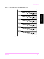
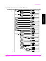
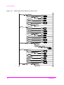
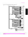
Appendix A, “Syntax Diagrams,”
This appendix shows a syntax diagram for each subsystem or command group.
Appendix B, “Command Difference between E6392A & E6392B,”
This appendix contains a table to show the command differences between the Agilent
E6392A and E6392B.
vii
viii
Contents
1. Preparing for Use
Equipment for Automated Test System . . . . . . . . . . . . . . . . . . . . . . . . . . . . . . . . . . .14
Connecting to Controller . . . . . . . . . . . . . . . . . . . . . . . . . . . . . . . . . . . . . . . . . . . . . .15
2. Programming Command Guidelines
Getting Started with Programming Commands . . . . . . . . . . . . . . . . . . . . . . . . . . . . .18
Understanding Common Terms . . . . . . . . . . . . . . . . . . . . . . . . . . . . . . . . . . . . . .18
Standard Notation . . . . . . . . . . . . . . . . . . . . . . . . . . . . . . . . . . . . . . . . . . . . . . . . .19
Command Syntax . . . . . . . . . . . . . . . . . . . . . . . . . . . . . . . . . . . . . . . . . . . . . . . . .20
Overview of the RS-232C Serial Interface . . . . . . . . . . . . . . . . . . . . . . . . . . . . . .22
Programming Guidelines . . . . . . . . . . . . . . . . . . . . . . . . . . . . . . . . . . . . . . . . . . .24
Using the Status Registers . . . . . . . . . . . . . . . . . . . . . . . . . . . . . . . . . . . . . . . . . . . . .25
Why Would You Use the Status Registers? . . . . . . . . . . . . . . . . . . . . . . . . . . . . .25
Status Register System . . . . . . . . . . . . . . . . . . . . . . . . . . . . . . . . . . . . . . . . . . . . .27
3. Programming Command Reference
IEEE Common Commands . . . . . . . . . . . . . . . . . . . . . . . . . . . . . . . . . . . . . . . . . . . . .34
IEEE Common Commands Reference . . . . . . . . . . . . . . . . . . . . . . . . . . . . . . . . .34
CONFigure Subsystem . . . . . . . . . . . . . . . . . . . . . . . . . . . . . . . . . . . . . . . . . . . . . . . .36
CONFigure Subsystem Command Reference . . . . . . . . . . . . . . . . . . . . . . . . . . .36
Command Reference for File Management Screen . . . . . . . . . . . . . . . . . . . . . . .38
Command Reference for Test Setup: Test Condition Screen . . . . . . . . . . . . . . . .40
Command Reference for Test Setup: Test Sequence Screen . . . . . . . . . . . . . . . .46
DISPlay Subsystem . . . . . . . . . . . . . . . . . . . . . . . . . . . . . . . . . . . . . . . . . . . . . . . . . . .56
Command Reference for Initial Screen . . . . . . . . . . . . . . . . . . . . . . . . . . . . . . . .56
Command Reference for AUTOMATIC TEST Screens . . . . . . . . . . . . . . . . . . .56
Command Reference for CONFIGURATION Screens . . . . . . . . . . . . . . . . . . . .57
Command Reference for MANUAL TEST Screens . . . . . . . . . . . . . . . . . . . . . .57
Command Reference for SIGNAL GENERATOR Screen . . . . . . . . . . . . . . . . .59
Command Reference for SPECTRUM MONITOR Screen . . . . . . . . . . . . . . . . .59
HCOPy Subsystem . . . . . . . . . . . . . . . . . . . . . . . . . . . . . . . . . . . . . . . . . . . . . . . . . . .60
HCOPy Subsystem Command Reference . . . . . . . . . . . . . . . . . . . . . . . . . . . . . . .60
RFGenerator Subsystem . . . . . . . . . . . . . . . . . . . . . . . . . . . . . . . . . . . . . . . . . . . . . . .61
RFGenerator Subsystem Command Reference . . . . . . . . . . . . . . . . . . . . . . . . . .61
SMONitor Subsystem . . . . . . . . . . . . . . . . . . . . . . . . . . . . . . . . . . . . . . . . . . . . . . . . .64
SMONitor Subsystem Command Reference . . . . . . . . . . . . . . . . . . . . . . . . . . . .64
SYSTem Subsystem . . . . . . . . . . . . . . . . . . . . . . . . . . . . . . . . . . . . . . . . . . . . . . . . . .68
SYSTem Subsystem Command Reference . . . . . . . . . . . . . . . . . . . . . . . . . . . . . .68
TESTs Subsystem for AUTOMATIC TEST . . . . . . . . . . . . . . . . . . . . . . . . . . . . . . .70
All Tests Results (Detail) . . . . . . . . . . . . . . . . . . . . . . . . . . . . . . . . . . . . . . . . . . .70
All Tests Results (Summary) . . . . . . . . . . . . . . . . . . . . . . . . . . . . . . . . . . . . . . . .71
Command Reference for Burst Timing/Power Ramp Measurement Screen . . . .72
9
Contents
Command Reference for DC Current Measurement Screen . . . . . . . . . . . . . . . . 74
Command Reference for MS Information . . . . . . . . . . . . . . . . . . . . . . . . . . . . . . 75
Command Reference for Peak TX Power Measurement Screen . . . . . . . . . . . . . 75
Command Reference for Phase/Frequency Error Measurement Screen . . . . . . . 76
Command Reference for Sensitivity/RX Quality/RX Level Measurement Screen 78
Command Reference for Stand-by/Measuring Screens . . . . . . . . . . . . . . . . . . . . 80
TESTs Subsystem for MANUAL TEST . . . . . . . . . . . . . . . . . . . . . . . . . . . . . . . . . . 84
Command Reference for DC Current Measurement Screen . . . . . . . . . . . . . . . . 84
Command Reference for Measuring Screens . . . . . . . . . . . . . . . . . . . . . . . . . . . 87
Command Reference for MS Information . . . . . . . . . . . . . . . . . . . . . . . . . . . . . . 93
Command Reference for Peak TX Power /Burst Timing/Power Ramp Measurement Screen
93
Command Reference for Phase/Frequency Error Measurement Screen . . . . . . . 98
Command Reference for Sensitivity/RX Quality/RX Level Measurement Screen 102
Command Reference for Spectrum Monitor Measurement Screen . . . . . . . . . . 106
Command Reference for Stand-by Screens . . . . . . . . . . . . . . . . . . . . . . . . . . . . 110
TRIGger Subsystem . . . . . . . . . . . . . . . . . . . . . . . . . . . . . . . . . . . . . . . . . . . . . . . . . 116
TRIGger Subsystem Command Reference . . . . . . . . . . . . . . . . . . . . . . . . . . . . 116
4. Programming Command Cross Reference
AUTOMATIC TEST Screens . . . . . . . . . . . . . . . . . . . . . . . . . . . . . . . . . . . . . . . . . 118
Stand-by/Measuring Screens . . . . . . . . . . . . . . . . . . . . . . . . . . . . . . . . . . . . . . . 118
Test Result Screens . . . . . . . . . . . . . . . . . . . . . . . . . . . . . . . . . . . . . . . . . . . . . . 120
CONFIGURATION Screen . . . . . . . . . . . . . . . . . . . . . . . . . . . . . . . . . . . . . . . . . . . 123
File Management Screens . . . . . . . . . . . . . . . . . . . . . . . . . . . . . . . . . . . . . . . . . 123
System Configuration Screen . . . . . . . . . . . . . . . . . . . . . . . . . . . . . . . . . . . . . . 124
Test Setup: Test Condition Screen . . . . . . . . . . . . . . . . . . . . . . . . . . . . . . . . . . . 125
Test Setup: Test Sequence Screen . . . . . . . . . . . . . . . . . . . . . . . . . . . . . . . . . . . 127
Display Each Screen . . . . . . . . . . . . . . . . . . . . . . . . . . . . . . . . . . . . . . . . . . . . . . . . 130
IEEE Common Commands . . . . . . . . . . . . . . . . . . . . . . . . . . . . . . . . . . . . . . . . . . . 132
MANUAL TEST Screens . . . . . . . . . . . . . . . . . . . . . . . . . . . . . . . . . . . . . . . . . . . . 133
Stand-by Screens . . . . . . . . . . . . . . . . . . . . . . . . . . . . . . . . . . . . . . . . . . . . . . . . 133
Measuring Screens . . . . . . . . . . . . . . . . . . . . . . . . . . . . . . . . . . . . . . . . . . . . . . . 135
DC Current Measuring Screens . . . . . . . . . . . . . . . . . . . . . . . . . . . . . . . . . . . . . 136
MS Information Screen . . . . . . . . . . . . . . . . . . . . . . . . . . . . . . . . . . . . . . . . . . . 137
Peak TX Power/Burst Timing/Power Ramp Measuring Screens . . . . . . . . . . . 138
Phase Error/Frequency Error Measuring Screens . . . . . . . . . . . . . . . . . . . . . . . 139
Sensitivity/RX Quality/RX Level Measuring Screens . . . . . . . . . . . . . . . . . . . 140
Spectrum Monitor Screens . . . . . . . . . . . . . . . . . . . . . . . . . . . . . . . . . . . . . . . . . 141
Print Screen Function . . . . . . . . . . . . . . . . . . . . . . . . . . . . . . . . . . . . . . . . . . . . . . . . 142
SIGNAL GENERATOR Screen . . . . . . . . . . . . . . . . . . . . . . . . . . . . . . . . . . . . . . . 143
SPECTRUM MONITOR Screens . . . . . . . . . . . . . . . . . . . . . . . . . . . . . . . . . . . . . . 144
10
Contents
System Control Function . . . . . . . . . . . . . . . . . . . . . . . . . . . . . . . . . . . . . . . . . . . . .145
Trigger Function . . . . . . . . . . . . . . . . . . . . . . . . . . . . . . . . . . . . . . . . . . . . . . . . . . . .146
5. Example Programs
MANUAL TEST SYNC Mode Sample Program . . . . . . . . . . . . . . . . . . . . . . . . . . .148
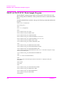
MANUAL TEST GPRS Mode Sample Program . . . . . . . . . . . . . . . . . . . . . . . . . . .153
AUTOMATIC TEST Sample Program . . . . . . . . . . . . . . . . . . . . . . . . . . . . . . . . . .158
A. Syntax Diagrams
B. Command Difference between E6392A & E6392B
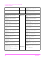
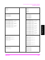
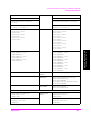
Changed Commands . . . . . . . . . . . . . . . . . . . . . . . . . . . . . . . . . . . . . . . . . . . . . . . . .180
Comparison Table for Command Difference . . . . . . . . . . . . . . . . . . . . . . . . . . .181
11
Contents
12
1. Preparing for Use
1
Preparing for Use
This chapter is a quick overview of how to set up an automated test system with
the Agilent E6392B GSM MS Test Set.
13
Preparing for Use
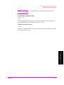
Equipment for Automated Test System
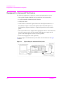
Equipment for Automated Test System
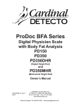
The following equipment is required to construct an automated test system:
•
The Agilent E6392B GSM MS Test Set (called the Test Set hereafter)
•
A system controller with the RS-232C interface
•
An RS-232C cable
•
An RF cable to connect RF signals from/to the mobile phone under test, or
the Antenna Coupler to connect RF signals from/to the mobile phone, or
the Shield Box (Agilent N4678A) to couple RF signals from/to the mobile
phone
•
The Universal DC Power Adapter and an appropriate cable to connect between
the AUX connector of the Test Set and the mobile phone to supply the dc
power to the mobile phone from the Test Set (optional)
•
Printer and an appropriate cable (optional)
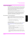
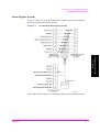
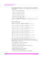
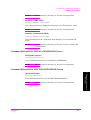
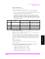
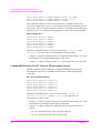
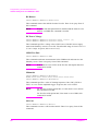
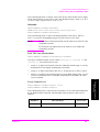
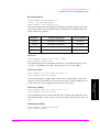
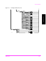
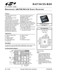
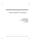
A typical setup for an automated test system looks like the illustration in Figure
1-1 below:
Figure 1-1
14
Typical Setup for Automated Test System
Chapter 1
Preparing for Use
Connecting to Controller
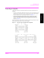
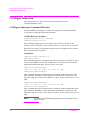
Connecting to Controller
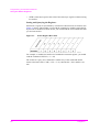
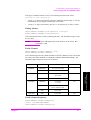
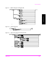
A DB-9 male connector is provided with the Test Set as the serial interface to a
controller.
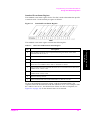
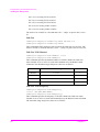
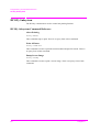
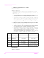
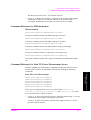
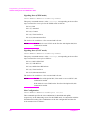
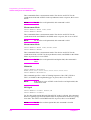
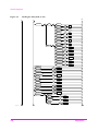
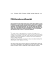
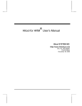
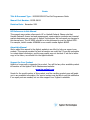
If your PC controller has a DB-9 male connector, use the 9-pin female to 9-pin
female RS-232C cable between the PC and the Test Set. This cable must have
the pin assignments shown in the upper illustration of Figure 1-2.
•
If your PC controller has a DB-25 male connector, insert the 9-pin male to
25-pin female Adapter between the RS-232C cable and the 25-pin male
connector. This adapter must have the pin assignments shown in the lower
diagram of Figure 1-2.
Agilent Technologies 34398A RS-232 Cable Kit contains a 9-pin female to 9-pin
female cable and 9-pin male to 25-pin female adapter.
Figure 1-2
Chapter 1
RS-232C Cable and Adapter Pin Assignments
15
1. Preparing for Use
•
Preparing for Use
Connecting to Controller
16
Chapter 1
2
Programming Command Guidelines
2. Programming Command
Guidelines
This chapter contains a brief overview of the programming commands.
17
Programming Command Guidelines
Getting Started with Programming Commands
Getting Started with Programming Commands
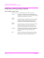
Understanding Common Terms
The following terms are used throughout the remainder of this chapter.
Controller
Program
Message
Response
Message
18
A controller is any computer used to communicate with an
instrument. A controller can be a personal computer (PC), a
minicomputer, or a plug-in card in a card cage. Some intelligent
instruments can also function as controllers.
A program message is a combination of one or more properly
formatted commands. Program messages always go from a
controller to an instrument. Program messages tell the
instrument how to make measurements and output signals.
A response message is a collection of data in specific formats.
Response messages always go from an instrument to a
controller. Response messages tell the controller about the
internal state of the instrument and about measured values.
Command
A command is an instruction. You combine commands to form
messages that control instruments. In general, a command
consists of mnemonics (keywords), parameters, and
punctuation.
Query
A query is a special type of command. Queries instruct the
instrument to make response data available to the controller.
Query mnemonics always end with a question mark, ?.
Chapter 2
Programming Command Guidelines
Getting Started with Programming Commands
Standard Notation
This section uses several forms of notation that have specific meaning:
Command Mnemonics Many commands have both a long and a short form and
you must use either one or the other (a combination of the two is
not allowed). Consider the :FREQuency command, for example.
The short form is :FREQ and the long form is :FREQUENCY.
This notation type is a shorthand to document both the long and
short form of commands. Programming commands are not case
sensitive, so :fREquEnCy is just as valid as :FREQUENCY, but
:FREQ and :FREQUENCY are the only valid forms of the
:FREQuency command.
Angle Brackets
Query and Event Commands
You can query any value that you can set. For example, the
:RESults:RAMP:MARKer:POSition <num> commands imply that the
:RESults:RAMP:MARKer:POSition? query commands also exist. If you see a
command ending with a question mark, it is a query-only command. Some
commands are events and cannot be queried. An event has no corresponding
setting if it causes something to happen inside the instrument at a particular instant.
Chapter 2
19
2. Programming Command
Guidelines
Angle brackets indicate that the word or words enclosed
represent something other than themselves. For example, <new
line> represents the ASCII character with the decimal value 10.
Words in angle brackets have much more rigidly defined
meaning than words shown in ordinary text. For example, this
section uses the word “message” to talk about messages
generally. But the bracketed words <program message> indicate
a precisely defined element of the commands. If you need them,
you can find the exact definitions of words such as <program
message> in a syntax diagram.
Programming Command Guidelines
Getting Started with Programming Commands
Command Syntax
Following the heading for each programming command entry is a syntax statement
showing the proper syntax for the command. An example syntax statement is
shown here:
CONFigure:PRINter HPPCL | ESCP
Syntax statements read from left to right. In this example, the :PRINter portion of
the statement immediately follows the :CONFigure portion of the statement with
no separating space. A separating space is legal only between the command and its
argument. In this example, the portion following the :PRINter portion of the
statement is the argument. Additional conventions used in the syntax statements
are defined as follows:
•
::= means “is defined as.”
•
| (vertical bar) indicates a choice of one element from a list. For example,
<A>|<B> indicates that either A or B can be chosen, but not both.
•
[] (square brackets) indicate that the enclosed items are optional.
•
<>(angle brackets) enclose variable items that represent user choices
(parameters) to be entered.
•
Upper-case lettering indicates that the upper-case portion of the command is
the minimum required for the command. For example, in the command
:FREQuency, :FREQ is the minimum requirement.
•
Lower-case lettering indicates that the lower-case portion of the command is
optional; it can be either included with the upper-case portion of the command
or omitted. For example, in the command :FREQuency, either :FREQ or
:FREQUENCY is correct.
•
? after a subsystem command indicates that the command is a query. Most
commands accept this command when it is entered immediately after the
command name. The returned information, <value>, varies in format according
to the type of the field.
•
;: (a semicolon and a colon) are used to separate two or more root level
command statements on the same line.
“:TEST:MAN:COND:PCL <num>;:TEST:MAN:SENS:LEV <num>”
•
; (a semicolon) can also be used to condense command words on one line if the
commands are equal, or of decreasing hierarchy under the keyword.
“:TEST:MAN:COND:PCL <num>;AMPL <num>”
20
Chapter 2
Programming Command Guidelines
Getting Started with Programming Commands
Units of Measure
•
Units for settings:
It is allowed to send numeric data with or without its multiplier and suffix as
follows. (Suffixes may be omitted if they are the default settings.)
HZ (Hz; default setting), KHZ (kHz), MHZ and MAHZ (MHz)
A (A; default), MA (mA)
PCT (%; default)
DB (dB; default)
DBM (dBm; default)
V (V; default)
For example, both of the following commands can set the same value:
TEST:AUTO:BCCH 896200000
TEST:AUTO:BCCH 896.2MHZ
Units for measurements:
The query responses for any parameters have only numerical or alphanumeric
data depending on the fields. For example, “TEST:AUTO:BCCH?” only
returns “896200000”.
Chapter 2
21
2. Programming Command
Guidelines
•
Programming Command Guidelines
Getting Started with Programming Commands
Overview of the RS-232C Serial Interface
Serial interface programming techniques are similar to most general I/O
applications. Refer to the programming language documentation for more
information on how to initiate the card and verify the status.
Due to the asynchronous nature of serial I/O operations, special care must be
exercised to ensure that data is not lost by sending to another device before the
device is ready to receive. Modem line handshaking can be used to help solve this
problem.
Settings for the Serial Interface
Refer to the documentation on your computer, programming language, and I/O
card to configure the serial bus.
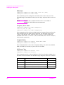
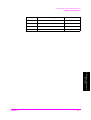
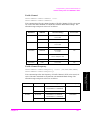
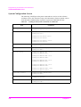
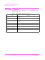
The serial port is not programmable but manually set. The default settings at preset
and other choices are as follows:
Table 2-1
Serial Port Configuration
Item
Default
Other Choices
Baud Rate:
9600
<fixed>
Data Length:
8
7
Stop Bits:
1
1.5, 2
Parity:
None
Odd, Even
Xcontrol:
None
Xon/Xoff
Terminator:
CR+LF
CR, LF
Use the following procedure to set the serial port configuration.
Step 1. Press the CONFIGURATION softkey in the Initial screen to obtain the
CONFIGURATION screen:
Step 2. Confirm that the Serial Port part is correctly set.
22
Chapter 2
Programming Command Guidelines
Getting Started with Programming Commands
Character Format Parameters
To define the character format, you must know the requirements of the peripheral
device for the following parameters:
•
Data Length: Eight data bits are used for each character, excluding start, stop,
and parity bits.
•
Stop Bits: One stop bit is included with each character.
•
Parity: Parity is disabled (absent) for each character.
Modem Line Handshaking
To use modem line handshaking for data transfer, set the Request-to-Send (RTS)
and Clear-to-Send (CTS) modem lines to active state on your controller.
Setting Xcontrol to Xon/Xoff allows the Test Set to stop data transmission from
the controller when the buffer of the Test Set is full and then start it again when the
Test Set is ready.
Data Transfer Errors
Chapter 2
•
Parity error. The parity bit on an incoming character does not match the parity
expected by the receiver. This condition is most commonly caused by line
noise.
•
Framing error. Start and stop bits do not match the timing expectations of the
receiver. This can occur when line noise causes the receiver to miss the start bit
or obscures the stop bits.
•
Overrun error. Incoming data buffer overrun caused a loss of one or more data
characters. This is usually caused when data is received by the interface, but no
ENTER statement has been activated to input the information.
•
Break received. A BREAK was sent to the interface by the peripheral device.
The computer program must be able to properly interpret the meaning of a
break and take appropriate action.
23
2. Programming Command
Guidelines
The serial interface can generate several types of errors when certain conditions
are encountered while receiving data from the peripheral device. Errors can be
generated by any of the following conditions:
Programming Command Guidelines
Getting Started with Programming Commands
Programming Guidelines
When you are going to make a test program, follow the following guidelines.
•
The program flow should be same as the flow of the front panel operation of
the Test Set. That is, before setting parameters, performing tests, or querying
the test results, display the corresponding screen using the DISPlay subsystem
commands.
For example, when you want to execute the BS Call for MANUAL TEST using
the “TESTs:MANual:MEASure:BSCall” command, send the
“DISPlay:MANual:SYNChronous:STBY” command to display the MANUAL
TEST: Stand-by screen before sending that command.
•
The number of query commands and the number of the corresponding enter
commands should be same. To avoid mismatching of the numbers of them,
enter the value to a computer just after the query commands have been sent.
For example, when you want to enter the TCH channel and frequency values on
MANUAL TEST using HP BASIC, make a test program as follows:
OUTPUT Serial_port;”DISP:MAN:SYNC:STBY”
OUTPUT Serial_port;”TEST:MAN:TCH:CHAN?”
ENTER Serial_port;a
OUTPUT Serial_port;”TEST:MAN:TCH:FREQ?”
ENTER Serial_port;b
24
•
To enter the measurement results, wait until the measurement ends. Using the
“*STB?” command to know the measurement status, monitor the bit 0,
Measurement Data Ready Bit, and bit 1, Measuring Status Bit.
•
To perform measurements with AUTOMATIC TEST or the MANUAL TEST,
wait until the test flow proceeds to the step which the measurement can be
performed. To monitor the test flow steps executed, use the
“TESTs:AUTO:MEASure:SIGNaling:STATe?” command for AUTOMATIC
TEST and the “TESTs:MANual:MEASure:SIGNaling:STATe?” command for
MANUAL TEST.
Chapter 2
Programming Command Guidelines
Using the Status Registers
Using the Status Registers
The status system comprises multiple registers which are arranged in a hierarchical
order. The lower-priority status registers propagate their data to the higher-priority
registers in the data structures by means of summary bits. The status byte register
is at the top of the hierarchy and contains the general status information for the
instrument’s events and conditions. All other individual registers are used to
determine the specific events or conditions.
You can determine the state of certain instrument hardware and firmware events
and conditions by programming the status register system.
Individual status registers can be set and queried using the commands in the IEEE
common commands reference. A status register is actually composed of five
physical registers: a condition register, two transition registers, an event enable
register and an event register. However, a “standard event status register” is
composed of an event enable register and an event register.
In general, your program often needs to be able to detect and manage error
conditions or changes in instrument status. To detect a change using the polling
method, the program must repeatedly read the registers to monitor a condition as
follows:
1. Determine which register contains the bit that reports the condition.
2. Send the unique query that reads that register.
3. Examine the bit to see if the condition has changed.
Using the Status Registers
Most monitoring of the instrument conditions is done at the highest level using the
IEEE common commands indicated below for the Test Set. Refer to “IEEE
Common Commands” on page 34 for more information about common
commands.
Chapter 2
•
*CLS (clear status) clears the status byte by emptying the error queue and
clearing all the event registers.
•
*ESE, *ESE? (event status enable) sets and queries the bits in the enable
register part of the standard event status register.
•
*ESR? (event status register) queries and clears the event register part of the
standard event status register.
•
*OPC, *OPC? (operation complete) sets or queries the standard event status
register to monitor the completion of all commands. The query stops any new
commands from being processed until the current processing is complete, then
returns a ‘1’.
25
2. Programming Command
Guidelines
Why Would You Use the Status Registers?
Programming Command Guidelines
Using the Status Registers
•
*STB? (status byte) queries the value of the status byte register without erasing
its contents.
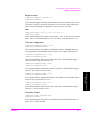
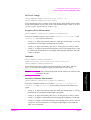
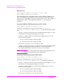
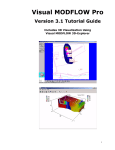
Setting and Querying the Registers
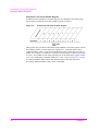
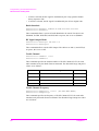
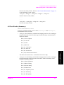
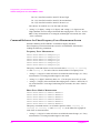
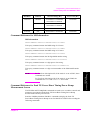
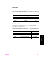
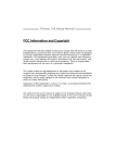
Each bit in a register is represented by a numerical value based on its location. See
Figure 2-1 below. This number is sent with the command, to enable a particular bit.
If you want to enable more than one bit, you would send the sum of all the bits that
you are interested in.
Figure 2-1
Status Register Bit Values
For example, to enable bit 0 and bit 6 of standard event status register, you would
send the command *ESE 65 (= 1 + 64).
The results of a query are evaluated in a similar way. If the command *STB?
returns a decimal value of 140 (= 128 + 8 + 4), then the bit 7, bit 3 and bit 2 are
true.
26
Chapter 2
Programming Command Guidelines
Using the Status Registers
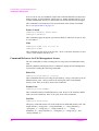
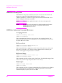
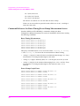
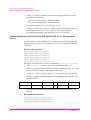
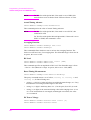
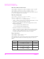
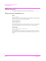
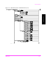
Status Register System
Figure 2-2 shows all of the instrument status registers of the Test Set and their
hierarchy incorporated with the Test Set.
Figure 2-2
Overall Status Byte Register System
2. Programming Command
Guidelines
Each of these status registers are explained in detail in the following sections.
Chapter 2
27
Programming Command Guidelines
Using the Status Registers
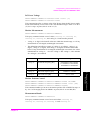
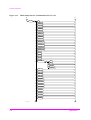
Status Byte Register
The status byte register of the Test Set uses the bit 0 “Measurement Data Ready
Bit”, bit 1 “Measuring Status Bit”, bit 4 “Message Available” and bit 5 “Standard
Event Status Summary Bit” as shown in Figure 2-3:
Figure 2-3
Status Byte Register
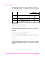
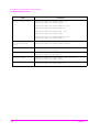
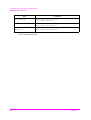
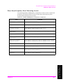
The status byte register contains the following bits:
Table 2-2
Bits in the Status Byte Register
Bit
Description
0
If the instrument has data ready in the output queue, this bit is set to 1. After
responding to a query this bit becomes 0.
1
While the instrument is in the measuring state, this bit is set to 1. At the
completion of one measurement, this bit is set to 0.
2, 3
These bits are always set to 0.
4
If the instrument has message data ready in the output queue, this bit is set to 1.
There are no lower status groups that provide input to this bit.
5
If the standard event summary bit has been set, this bit is set to 1. The standard
event status register can then be read to determine the specific event that
caused this bit to be set.
6, 7
These bits are always set to 0.
To query the status byte register, send the command *STB?. The response will be
the decimal sum of the bits which are set to 1. For example, if the bit 5 and bit 4 are
set to 1, the decimal sum of these two bits is 32 plus 16 (see Figure 2-1 on page
26). So the decimal value 48 is returned.
28
Chapter 2
Programming Command Guidelines
Using the Status Registers
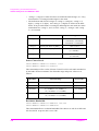
Standard Event Status Register
The standard event status register for the Test Set is used to determine the specific
event that set bit 5 in the status byte register as follows:
Figure 2-4
Standard Event Status Register
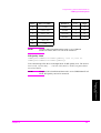
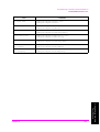
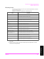
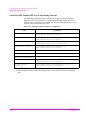
The standard event status register contains the following bits:
Table 2-3
Bits in the Standard Event Status Register
Bit
Description
If all pending operations were completed following execution of the *OPC
command, this bit is set to 1.
1
This bit is always set to 0.
2
If a query error has occurred, this bit is set to 1.
3
If a device dependent error has occurred, this bit is set to 1. Device dependent
errors have error numbers from −399 to −300 and 1 to 32767.
4
If an execution error has occurred, this bit is set to 1. Execution errors have error
numbers from −299 to −200.
5
If a command error has occurred, this bit is set to 1. Command errors have error
numbers from −199 to −100.
6
This bit is always set to 0.
7
If the instrument has been turned off and then on, this bit is set to 1.
To query the standard event status register, send the command *ESR?. The
response will be the decimal sum of the bits which are set to 1. For example, if the
bit 7 and bit 3 are set to 1, the decimal sum of these two bits is 128 plus 8 (see
Figure 2-1 on page 26). So the decimal value 136 is returned.
Chapter 2
29
2. Programming Command
Guidelines
0
Programming Command Guidelines
Using the Status Registers
Standard Event Status Enable Register
In addition to the standard event status register, the standard event status group
also contains a standard event status enable register as follows:
Figure 2-5
Standard Event Status Enable Register
This register lets you choose which bits in the standard event status register will set
the summary bit (bit 5 of the status byte register) to 1. Send the *ESE <num>
command where <num> is the sum of the decimal values of the bits you want to
enable. For example, to enable bit 7 and bit 6 so that whenever either of those bits
is set to 1, the standard event status summary bit of the status byte register will be
set to 1 by sending the command *ESE 192 (= 128 + 64) (see Figure 2-1 on page
26). The command *ESE? returns the decimal value of the sum of the bits
previously enabled with the *ESE <num> command.
30
Chapter 2
Programming Command Guidelines
Using the Status Registers
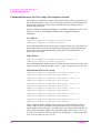
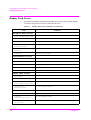
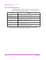
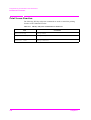
Error Messages
The following table shows the error messages for the Test Set.
Table 2-4
Error Messages
Error No.
0
No error
−100
Other command error has occurred.
−103
Command error due to an invalid separator
−112
Command error due to a program mnemonic that is too long
−113
Command error due to an undefined header
−120
Command error due to a numeric data error
−123
Command error due to an exponent that is too large
−124
Command error due to too many digits
−131
Command error due to an invalid suffix
−141
Command error due to invalid character data
−144
Command error due to character data that is too long
−200
Execution error due to an invalid command
−222
Execution error due to data that is out of range
−350
Device dependent error due to a queue overflow
2. Programming Command
Guidelines
Chapter 2
Description
31
Programming Command Guidelines
Using the Status Registers
32
Chapter 2
3
Programming Command Reference
This chapter contains a listing of all of the SCPI subsystem commands and
subcommands in alphabetical order. The descriptions include syntax requirements,
ranges, restrictions, query responses, and status at instrument preset.
3. Programming Command
Reference
33
Programming Command Reference
IEEE Common Commands
IEEE Common Commands
The following IEEE common commands are used to set and monitor the status
registers, and to reset the Test Set.
IEEE Common Commands Reference
Clear Status
*CLS
This command initializes the status byte register (STBR) and the standard event
status register (SESR).
Event Status Register Query
*ESR?
This query command returns a value of the standard event status register (SESR).
The range of a value is from 0 to 255.
Identification Query
*IDN?
This query command returns a string of “AGILENT TECHNOLOGIES,
E6392B, <serial number>, <firmware revision number>”.
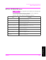
Instrument Option Query
*OPT?
This query command returns a value of the option numbers installed in the Test Set
as follows:
000
No option
002
Asynchronous Test Mode for MANUAL TEST
040
GPRS Test Mode for MANUAL TEST
Operation Complete
*OPC
*OPC?
This command enables or queries the OPC bit of the standard event status register
(SESR). The query command returns 1.
Reset
*RST
This command executes to run the selftest routine and resets the Test Set to the
initial state.
34
Chapter 3
Programming Command Reference
IEEE Common Commands
NOTE
The *RST command does not affect the settings for the serial
interface.
Standard Event Status Enable
*ESE <int>
*ESE?
This command specifies or queries a value of the standard event status enable
register (SESER). The allowable range is from 0 to 255.
Status Byte Register Query
*STB?
This query command returns a value of the status byte register (STBR). The range
of a value is from 0 to 255.
3. Programming Command
Reference
Chapter 3
35
Programming Command Reference
CONFigure Subsystem
CONFigure Subsystem
This subsystem sets or queries the controls and parameters on the
CONFIGURATION screen.
CONFigure Subsystem Command Reference
Send the "DISPlay:CONFigure" command to display the CONFIGURATION
screen before sending the following commands.
13 MHz Reference Oscillator
CONFigure:ROSCillator INT|EXT
CONFigure:ROSCillator?
This command toggles the reference signal to be used, between INT for the
internal reference and EXT for the external reference. At preset, this is set to INT.
When EXT is selected, an appropriate signal needs to be supplied to the 13 MHz
Reference port on the rear panel.
Attenuation
CONFigure:LOSS ON|OFF|1|0
CONFigure:LOSS?
This command toggles the attenuation function between ON (1) and OFF (0). If set
to On, the attenuations for the radio standards are activated to be used in the RF
input path and RF output path. At preset, this is set to OFF.
CONFigure:LOSS:RFINput
<real 1>,<real 2>,<real 3>,<real 4> [DB]
CONFigure:LOSS:RFINput?
This command specifies the insertion losses caused by the RF Input path for the
radio standards, GSM900, E-GSM, DCS1800, and PCS1900, respectively. The
allowable range is from 0.0 to 99.9 (dB) in 0.1 steps. At preset, these are set to 0.0
(dB).
CONFigure:LOSS:RFOUtput
<real 1>,<real 2>,<real 3>,<real 4> [DB]
CONFigure:LOSS:RFOUtput?
This command specifies the insertion losses caused by the RF Output path for the
radio standards, GSM900, E-GSM, DCS1800, and PCS1900, respectively. The
allowable range is from 0.0 to 99.5 (dB) in 0.5 steps. At preset, these are set to 0.0
(dB).
NOTE
36
For SIGNAL GENERATOR applications, the attenuations for RF
output are used.
Chapter 3
Programming Command Reference
CONFigure Subsystem
Beeper Control
CONFigure:BEEPer ON|OFF|1|0
CONFigure:BEEPer?
This command toggles the beeper function between ON (1) and OFF (0). If set to
ON, there is a beep for each step of operation. If set to OFF, beeps excepting for
some errors and warnings are suppressed. At preset, this is set to ON.
Date
CONFigure:DATE <int y>,<int m>,<int d>
CONFigure:DATE?
This command defines the test date of the Test Set. <int y> is the year from 1990 to
2089, <int m> is the month from 01 to 12, and <int d> is the day from 01 to 31.
Network Configuration
CONFigure:NETWork:BSPa <int>
CONFigure:NETWork:BSPa?
This command defines the number of multiframes (BS_PA_MFRMS) between
two transmissions. The allowable range is from 2 to 9. At preset, this is set to 2.
CONFigure:NETWork:LAC <int>
CONFigure:NETWork:LAC?
This command defines the Location Area Code (LAC). The allowable range is
from 0 to 65535. At preset, this is set to 1.
CONFigure:NETWork:MCC <int>
CONFigure:NETWork:MCC?
This command defines the Mobile Country Code (MCC). The allowable range is
from 0 to 999. At preset, this is set to 1.
This command defines the Mobile Network Code (MNC). The allowable range is
from 0 to 99. At preset, this is set to 1.
CONFigure:NETWork:NCC <int>
CONFigure:NETWork:NCC?
This command defines the Network Color Code (NCC). The allowable range is
from 0 to 7. At preset, this is set to 1.
Panel Key Control
CONFigure:PKEY UNLOCK|LOCK
CONFigure:PKEY?
This command toggles the panel key control between UNLOCK and LOCK. At
preset, this is set to UNLOCK.
Chapter 3
37
3. Programming Command
Reference
CONFigure:NETWork:MNC <int>
CONFigure:NETWork:MNC?
Programming Command Reference
CONFigure Subsystem
If set to LOCK, only AUTOMATIC TEST and CONFIGURATION are allowed to
change settings. In AUTOMATIC TEST, however, Radio Standard, BCCH, TCH
(TALK), Multi Band, DC Power, and Variable are locked and cannot be changed.
This command is not identical to Lock System Panel of the System commands.
See “Lock System Panel” on page 68.
Printer Control
CONFigure:PRINter HPPCL|ESCP
CONFigure:PRINter?
This command toggles the printer type between HPPCL and ESCP. At preset, this
is set to HPPCL.
Time
CONFigure:TIME <int h>,<int m>
CONFigure:TIME?
This command sets the clock of the Test Set. <int h> is the hour from 00 to 23 and
<int m> is the minutes from 00 to 59.
Command Reference for File Management Screen
The File commands are used to manage the test setup files on an SRAM memory
card.
Send the "DISPlay:CONFigure:FILE" command to display the File Management
screen before sending the following commands.
Delete File
CONFigure:FILE:DELete <string>
This command deletes the test setup file specified by <string> (file name) from an
SRAM memory card. <string> must be an existing file name on the SRAM
memory card. There is no query form of this command.
Format Card
CONFigure:FILE:FORMat
This command initializes an SRAM memory card, however, the firmware update
cards can not be initialized. There is no query form of this command.
List Files
CONFigure:FILE:LIST?
This query command returns a list of all setup files in an SRAM memory card. The
output format is <string total>, <string filenumber_1>, <string filename_1>,
<string date_1>, <string time_1>, <string comment_1>, ... , <string
filenumber_n>, <string filename_n>, <string date_n>, <string time_n>, and
<string commnet_n>.
38
Chapter 3
Programming Command Reference
CONFigure Subsystem
•
<string total> (3 digits) is the total number of setup files in a SRAM memory
card ranging from 000 to 100.
•
<string filenumber_n> (3 digits) is the "n-th" file number ranging from 000 to
100,
•
<string filename_n> (8 letters) is the file name of the n-th file,
•
<string date_n> (10 digits) is the date in "yyyy/mm/dd" format stored in the
n-th file,
•
<string time_n> (5 digits) is the time in "hh:mm" format stored in the n-th file,
•
<string comment_n> (23 letters) is the comment of the n-th file,
where “n” ranges from 1 to the last number of the files in an SRAM card.
Recall File
CONFigure:FILE:RECall <string>
This command loads the test setup file specified by <string> (file name) from an
SRAM memory card into the internal memory of the Test Set. <string> must be an
existing file name in the SRAM memory card. There is no query form of this
command.
Save File
CONFigure:FILE:SAVE <string filename>,<string comment>
This command saves the current settings of the Test Set into an SRAM memory
card. <string filename> accepts up to 8 alphanumeric characters. <string
comment> accepts up to 23 alphanumeric characters. Date and Time are
automatically given by the Test Set. There is no query form of this command.
3. Programming Command
Reference
Chapter 3
39
Programming Command Reference
CONFigure Subsystem
Command Reference for Test Setup: Test Condition Screen
The Condition commands are used to set the controls and parameters associated
with the test condition including the pass/fail test limits for AUTOMATIC TEST
and MANUAL TEST. The query commands return the settings of those controls
and parameters.
Send the "DISPlay:CONFigure:CONDition" command to display the Test Setup:
Test Condition screen before sending the following commands.
NOTE
If Option 040 is installed and the mode is set to GPRS, the test
items FER, BER, RX Quality, and RX Level for sensitivity tests
can not be displayed in MANUAL TEST, however these can be
configured. One command for Sensitivity in BLER is added to the
GPRS mode.
Averaging Function
CONFigure:CONDition:AVERage OFF|<int>
CONFigure:CONDition:AVERage?
This command defines whether or not to activate the averaging function. The
choices are OFF and <int> for the number of averaging times. The allowable range
of <int> is from 2 to 99. At preset, this is set to OFF.
BER BS Level
CONFigure:CONDition:SENSitivity:LEVel <real> [DBM]
CONFigure:CONDition:SENSitivity:LEVel?
This command specifies an amplitude of the Test Set for error ratio tests, for each
radio standard set by the Radio Format command. The allowable range is from
−110.0 to −50.0 (dBm) in 0.5 steps. At preset, this is set to −102.0 (dBm) for
GSM900 and E-GSM, −100.0 (dBm) for DCS1800, or −102.0 (dBm) for
PCS1900.
BER Frames
CONFigure:CONDition:SENSitivity:FRAMe <int>
CONFigure:CONDition:SENSitivity:FRAMe?
This command specifies the number of the Test Set for error ratio tests. The
allowable range is from 1 to 13000 (frames) in 1 steps. At preset, this is set to 10
(frames).
BER Limit
CONFigure:CONDition:LIMit:BER <real h> [PCT]
CONFigure:CONDition:LIMit:BER?
This command specifies the high limit for BER (bit error ratio) tests. The
allowable range is from 0.00 to 99.99 (%) in 0.01 steps. At preset, this is set to 2.44
(%).
40
Chapter 3
Programming Command Reference
CONFigure Subsystem
NOTE
If Option 040 is installed and the mode is set to GPRS, BER can
noe is measured in MANUAL TEST.
BLER Limit
CONFigure:CONDition:LIMit:BLER <real h> [PCT]
CONFigure:CONDition:LIMit:BLER?
This command specifies the high limit for BLER (block error ratio) tests if Option
040 is installed and the GPRS mode is selected. The allowable range is from 0.00
to 99.99 (%) in 0.01 steps. At preset, this is set to 2.44 (%).
NOTE
If the mode is set to GPRS on the Test Set with Option 040,
Sensitivity in BLER is measured in MANUAL TEST.
BS Level
CONFigure:CONDition:AMPLitude <real> [DBM]
CONFigure:CONDition:AMPLitude?
This command specifies an amplitude of the Test Set applied to the mobile under
test. The allowable range is from −110.0 to −50.0 (dBm) in 0.5 steps. At preset,
this is set to −50.0 (dBm).
Burst Timing Limit
CONFigure:CONDition:LIMit:BTIMing
<real l>,<real h> [Bits]
CONFigure:CONDition:LIMit:BTIMing?
This command specifies the low and high limits for Burst Timing tests. The
allowable range is from −9.9 to +9.9 (bits) in 0.1 steps. At preset, these are set to
−1.0 and +1.0 (bits).
CONFigure:CONDition:LIMit:CURRent:CAMP
<int l>,<int h> [MA]
CONFigure:CONDition:LIMit:CURRent:CAMP?
CONFigure:CONDition:LIMit:CURRent:TALK
<int l>,<int h> [MA]
CONFigure:CONDition:LIMit:CURRent:TALK?
This command specifies the low and high limits for DC Current tests at Camp On
or Talk. The allowable range is from 3 to 1000 (mA) in 1 steps. At preset, these are
set to 50 and 200 (mA) for Camp On, and 300 and 700 (mA) for Talk, respectively.
NOTE
If Option 002 is installed and the mode is set to ASYNC in
MANUAL TEST, the limits for Talk are used for DC Current tests.
If Option 040 is installed and the mode is set to GPRS in
MANUAL TEST, the limits for Talk are used for DC Current tests.
Chapter 3
41
3. Programming Command
Reference
DC Current Limit
Programming Command Reference
CONFigure Subsystem
FER Limit
CONFigure:CONDition:LIMit:FER <real h> [PCT]
CONFigure:CONDition:LIMit:FER?
This command specifies the high limit for FER (frame erasure rate) tests. The
allowable range is from 0.00 to 99.99 (%) in 0.01 steps. At preset, this is set to 0.12
(%).
NOTE
If Option 040 is installed and the mode is set to GPRS in
MANUAL TEST, FER can not be measured.
Frequency Error Limit
CONFigure:CONDition:LIMit:FREQuency
<int l>,<int h> [HZ]
CONFigure:CONDition:LIMit:FREQuency?
This command specifies the low and high limits for Frequency Error tests for each
radio standard set by the Radio Format command. The allowable range is from
−999 to +999 (Hz) in 1 steps. At preset, these are set to −90 and +90 (Hz) for
GSM900 and E-GSM, −171 and +171 (Hz) for DCS1800, and −185 and +185 (Hz)
for PCS1900, respectively.
Loopback Delay
CONFigure:CONDition:LDELay SHORT|MID|LONG
CONFigure:CONDition:LDELay?
This command defines a time value of Loopback Delay. The choices are SHORT,
MID, and LONG (2 seconds). At preset, this is set to MID.
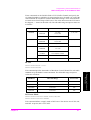
MS Power Class
CONFigure:CONDition:PCLass <int>
CONFigure:CONDition:PCLass?
This command specifies a value of MS Power Class for each radio standard set by
the Radio Format command. The allowable range and preset values are as follows:
42
RFORmat
Allowable Range
Preset Value
GSM900
2 (+39 dBm) to 5 (+29 dBm)
4 (+33 dBm)
E-GSM
2 (+39 dBm) to 5 (+29 dBm)
4 (+33 dBm)
DCS1800
1 (+30 dBm), 2 (+24 dBm), 3 (+36 dBm)
1 (+30 dBm)
PCS1900
1 (+30 dBm), 2 (+24 dBm), 3 (+33 dBm)
1 (+30 dBm)
Chapter 3
Programming Command Reference
CONFigure Subsystem
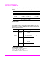
Peak TX Power Limit
CONFigure:CONDition:LIMit:TPOWer
<int>,<real l>,<real h> [DB]
CONFigure:CONDition:LIMit:TPOWer?
This command specifies a value of Power Control Level (PWR CNTL) and the
low and high limits for Peak TX Power tests, for each radio standard set by the
Radio Format command. The allowable limit range for <real l> and <real h> is
from −99.9 to +99.9 (dB) in 0.1 steps. At preset, these are set to −3.0 and +3.0
(dB); an exception is that, for LOW level tests of DCS1800 or PCS1900, the preset
values are −4.0 and +4.0 (dB). The power control level and the preset values are as
follows:
RFORmat
Allowable Range for <int>
Preset Value
GSM900
2 (+39 dBm) to 19 (+5 dBm)
5 (+33 dBm)
E-GSM
2 (+39 dBm) to 19 (+5 dBm)
5 (+33 dBm)
DCS1800
0 (+30 dBm) to 15 (+0 dBm), or
29 (+36 dBm) to 31 (+32 dBm)
0 (+30 dBm)
PCS1900
0 (+30 dBm) to 15 (+0 dBm), or
30 (+33 dBm) to 31 (+32 dBm)
0 (+30 dBm)
Phase Error Limit
CONFigure:CONDition:LIMit:PHASe:PEAK <real h> [DEG]
CONFigure:CONDition:LIMit:PHASe:PEAK?
CONFigure:CONDition:LIMit:PHASe:RMS <real h> [DEG]
CONFigure:CONDition:LIMit:PHASe:RMS?
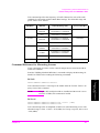
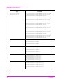
Power Control Level
CONFigure:CONDition:PLEVel:HIGH <int>
CONFigure:CONDition:PLEVel:HIGH?
CONFigure:CONDition:PLEVel:MEDium <int>
CONFigure:CONDition:PLEVel:MEDium?
CONFigure:CONDition:PLEVel:LOW <int>
CONFigure:CONDition:PLEVel:LOW?
CONFigure:CONDition:PLEVel:MANual <int>
CONFigure:CONDition:PLEVel:MANual?
Chapter 3
43
3. Programming Command
Reference
This command specifies the high limit for Peak or RMS Phase Error tests. The
allowable range is from 0.0 to 99.9 (°) in 0.1 steps. At preset, these are set to 20.0
(°) for peak and 5.0 (°) for rms.
Programming Command Reference
CONFigure Subsystem
This command sets a value of Power Control Level (PWR CNTL) to each of the
High, Medium, and Low ranges for AUTOMATIC TEST, or sets a value of PWR
CNTL for MANUAL TEST, for each radio standard set by the Radio Format
command. The allowable range and preset values are as follows:
Preset Value
RFORmat
Allowable Range
AUTO
MANUAL
GSM900
2 (+39 dBm) to 19 (+5 dBm)
5, 10, 15
5
E-GSM
2 (+39 dBm) to 19 (+5 dBm)
5, 10, 15
5
DCS1800
0 (+30 dBm) to 15 (+0 dBm), or
29 (+36 dBm) to 31 (+32 dBm)
0, 5, 10
0
PCS1900
0 (+30 dBm) to 15 (+0 dBm), or
30 (+33 dBm) to 31 (+32 dBm)
0, 5, 10
0
Radio Standard
CONFigure:CONDition:RFORmat
GSM900|E-GSM|DCS1800|PCS1900
CONFigure:CONDition:RFORmat?
This command defines a system of Radio Standard to be tested. The choices are
GSM900, E-GSM, DCS1800, and PCS1900. At preset, this is set to GSM900.
RF Output
CONFigure:CONDition:RFOUtput AUTO|ON
CONFigure:CONDition:RFOUtput?
This command defines a mode of RF Output. The choices are AUTO and ON. If
set to AUTO, the RF signal is supplied only during test cycles. At preset, this is set
to ON.
RX Level Limit
CONFigure:CONDition:LIMit:LEVel <int l>,<int h>
CONFigure:CONDition:LIMit:LEVel?
This command specifies the low and high limits for RX Level tests, for each radio
standard set by the Radio Format command. The choices and the preset values are
as follows:
44
Chapter 3
Programming Command Reference
CONFigure Subsystem
Preset Values
Choice
RX Level [dBm]
RFORmat
Low
High
0
<−110
GSM900
5
12
1
−110 to −109
E-GSM
5
12
2
−109 to −108
DCS1800
7
14
.....
.....
PCS1900
5
12
62
−49 to −48
63
>−48
NOTE
If Option 040 is installed and the mode is set to GPRS in
MANUAL TEST, RX Level can not be measured.
RX Quality Limit
CONFigure:CONDition:LIMit:QUALity <int l>,<int h>
CONFigure:CONDition:LIMit:QUALity?
This command specifies the low and high limits for RX Quality tests. The choices
are 0 (<0.2), 1 (0.2 to 0.4), ......, 6 (6.4 to 12.8), and 7 (>12.8%). At preset, these
are set to 0 and 4.
NOTE
If Option 040 is installed and the mode is set to GPRSin MANUAL
TEST, RX Quality can not be measured.
3. Programming Command
Reference
Chapter 3
45
Programming Command Reference
CONFigure Subsystem
Command Reference for Test Setup: Test Sequence Screen
The Sequence commands are used to control the test flow and test sequences, and
also to define whether or not to execute pass/fail tests for the six measurements at
the specified TCH or DCP. The query commands return the settings of those
controls and parameters.
Send the "DISPlay:CONFigure:SEQuence" command to display the Test Set: Test
Sequence screen for AUTOMATIC TEST before sending the following
commands.
1st Call Test
CONFigure:SEQuence:SIGNaling:CALL1 MS|BS
CONFigure:SEQuence:SIGNaling:CALL1?
This command defines the first caller at the second test flow step. The choices are
MS and BS. If MS is selected, the fifth step automatically becomes MS Release,
and the sixth and seventh automatically become BS Call and BS Release. At
preset, this is set to MS.
2nd Call Test
CONFigure:SEQuence:SIGNaling:CALL2 ON|OFF|1|0
CONFigure:SEQuence:SIGNaling:CALL2?
This command defines whether or not to include the second call in a test flow. The
choices are ON (1) for Run and OFF (0) for --- (skip). At preset, this is set to ON.
6 Measurement DC Power Loop
CONFigure:SEQuence:VARiable:DCP:VOLT1 <real> [V]
CONFigure:SEQuence:VARiable:DCP:VOLT1?
CONFigure:SEQuence:VARiable:DCP:VOLT2 <real> [V]
CONFigure:SEQuence:VARiable:DCP:VOLT2?
CONFigure:SEQuence:VARiable:DCP:VOLT3 <real> [V]
CONFigure:SEQuence:VARiable:DCP:VOLT3?
CONFigure:SEQuence:VARiable:DCP:VOLT4 <real> [V]
CONFigure:SEQuence:VARiable:DCP:VOLT4?
CONFigure:SEQuence:VARiable:DCP:VOLT5 <real> [V]
CONFigure:SEQuence:VARiable:DCP:VOLT5?
CONFigure:SEQuence:VARiable:DCP:VOLT6 <real> [V]
CONFigure:SEQuence:VARiable:DCP:VOLT6?
These commands set the Variable field to DC Power (DCP) and specify the six
voltage values of DCP at which the six measurements are to be made. The DC
Power supply mode needs to be set to either Auto or On. These measurements are
made at one fixed traffic channel. The allowable range is from 3.0 to 11.0 (V) in
0.1 steps. The value 99.9 causes the DCP test to be skipped (---- shown in the table
cell). At preset, these are set to 3.0 (V).
46
Chapter 3
Programming Command Reference
CONFigure Subsystem
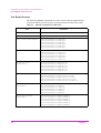
6 Measurement Traffic Channel Loop
CONFigure:SEQuence:VARiable:TCH:CHANnel1 <int>
CONFigure:SEQuence:VARiable:TCH:CHANnel1?
CONFigure:SEQuence:VARiable:TCH:CHANnel2 <int>
CONFigure:SEQuence:VARiable:TCH:CHANnel2?
CONFigure:SEQuence:VARiable:TCH:CHANnel3 <int>
CONFigure:SEQuence:VARiable:TCH:CHANnel3?
CONFigure:SEQuence:VARiable:TCH:CHANnel4 <int>
CONFigure:SEQuence:VARiable:TCH:CHANnel4?
CONFigure:SEQuence:VARiable:TCH:CHANnel5 <int>
CONFigure:SEQuence:VARiable:TCH:CHANnel5?
CONFigure:SEQuence:VARiable:TCH:CHANnel6 <int>
CONFigure:SEQuence:VARiable:TCH:CHANnel6?
These commands set the Variable field to TCH (Traffic Channel) and specify the
six channel numbers at which the six measurements are to be made, for each radio
standard in conjunction with the Multi Band setting. These measurements are
made at one fixed voltage of DC Power. The value 9999 causes the TCH test to be
skipped (---- shown in the table cell). The allowable range and preset values are as
follows:
RFORmat
MBANd
Allowable Range
Preset Value
1 to 124;
512 to 885
1, 62, 124
DCS1800
OFF
1 to 124
DCS1800
0 to 124|975 to 1023;
512 to 885
OFF
0 to 124|975 to 1023
GSM900
512 to 885;
1 to 124
E-GSM
512 to 885;
0 to 124|975 to 1023
OFF
512 to 885
OFF
512 to 810
GSM900
E-GSM
PCS1900
512, 699, 885
512, 661, 810
BCCH Channel
CONFigure:SEQuence:BCCH:CHANnel <int>
CONFigure:SEQuence:BCCH:CHANnel?
Chapter 3
47
3. Programming Command
Reference
DCS1800
1, 62, 124
Programming Command Reference
CONFigure Subsystem
This command specifies the channel number of Broadcast Control Channel
(BCCH) for each radio standard set by the Radio Format command. The allowable
range and preset values are as follows:
RFORmat
Allowable Range
Preset Value
GSM900
1 to 124
20
E-GSM
0 to 124, 975 to 1023
20
DCS1800
512 to 885
698
PCS1900
512 to 810
698
BCCH Frequency
CONFigure:SEQuence:BCCH:FREQuency
<real> [HZ|KHZ|MHZ|MAHZ]
CONFigure:SEQuence:BCCH:FREQuency?
This command specifies the frequency of Broadcast Control Channel (BCCH) for
each radio standard set by the Radio Format command. The allowable range and
preset values are as follows:
RFORmat
Allowable Range [Hz]
Preset Value [Hz]
GSM900
890200000 to 914800000
890200000
E-GSM
880200000 to 914800000
890200000
DCS1800
1710200000 to 1784800000
1710200000
PCS1900
1850200000 to 1909800000
1850200000
Burst Timing Test
CONFigure:SEQuence:BTIMing <int>
CONFigure:SEQuence:BTIMing?
This command defines whether or not to include Burst Timing tests in the test
sequence for the six measurements. <int> is a binary coded decimal ranging from 0
to 63 as follows:
bit 0 (1): For testing TCH1 or DCP1
bit 1 (2): For testing TCH2 or DCP2
bit 2 (4): For testing TCH3 or DCP3
bit 3 (8): For testing TCH4 or DCP4
bit 4 (16): For testing TCH5 or DCP5
bit 5 (32): For testing TCH6 or DCP6
48
Chapter 3
Programming Command Reference
CONFigure Subsystem
The choices for each bit are 1 for Run and 0 for --- (skip). At preset, this is set to
63.
DC Current Test
CONFigure:SEQuence:CURRent <int>
CONFigure:SEQuence:CURRent?
This command defines whether or not to include DC Current tests in the test
sequence for the six measurements. <int> is a binary coded decimal ranging from 0
to 63 as follows:
bit 0 (1): For testing TCH1 or DCP1
bit 1 (2): For testing TCH2 or DCP2
bit 2 (4): For testing TCH3 or DCP3
bit 3 (8): For testing TCH4 or DCP4
bit 4 (16): For testing TCH5 or DCP5
bit 5 (32): For testing TCH6 or DCP6
The choices for each bit are 1 for Run and 0 for --- (skip). At preset, this is set to
63.
DC Power Mode
CONFigure:SEQuence:DCPower:MODE AUTO|ON|OFF
CONFigure:SEQuence:DCPower:MODE?
This command defines a supply mode of DC Power. The choices are AUTO, ON,
and OFF. At preset, this is set to OFF.
If set to AUTO, DC Power is supplied during a measurement cycle or until a
measurement is aborted.
•
If set to ON, DC Power is always supplied.
•
If set to OFF, DC Power is not supplied and the Variable field is automatically
set to TCH.
DC Power Voltage
CONFigure:SEQuence:DCPower:VOLT <real> [V]
CONFigure:SEQuence:DCPower:VOLT?
This command specifies a voltage value of DC Power. The allowable range is from
3.0 to 11.0 (V) in 0.1 steps. At preset, this is set to 3.0 (V).
Frequency Error Test
CONFigure:SEQuence:FREQuency <int>
CONFigure:SEQuence:FREQuency?
Chapter 3
49
3. Programming Command
Reference
•
Programming Command Reference
CONFigure Subsystem
This command defines whether or not to include Frequency Error tests in the test
sequence for the six measurements. <int> is a binary coded decimal ranging from 0
to 63 as follows:
bit 0 (1): For testing TCH1 or DCP1
bit 1 (2): For testing TCH2 or DCP2
bit 2 (4): For testing TCH3 or DCP3
bit 3 (8): For testing TCH4 or DCP4
bit 4 (16): For testing TCH5 or DCP5
bit 5 (32): For testing TCH6 or DCP6
The choices for each bit are 1 for Run and 0 for --- (skip). At preset, this is set to
63.
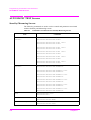
Instruction Message #
CONFigure:SEQuence:SIGNaling:MESSage1 <string>
CONFigure:SEQuence:SIGNaling:MESSage1?
CONFigure:SEQuence:SIGNaling:MESSage2 <string>
CONFigure:SEQuence:SIGNaling:MESSage2?
CONFigure:SEQuence:SIGNaling:MESSage3 <string>
CONFigure:SEQuence:SIGNaling:MESSage3?
CONFigure:SEQuence:SIGNaling:MESSage4 <string>
CONFigure:SEQuence:SIGNaling:MESSage4?
CONFigure:SEQuence:SIGNaling:MESSage5 <string>
CONFigure:SEQuence:SIGNaling:MESSage5?
CONFigure:SEQuence:SIGNaling:MESSage6 <string>
CONFigure:SEQuence:SIGNaling:MESSage6?
CONFigure:SEQuence:SIGNaling:MESSage7 <string>
CONFigure:SEQuence:SIGNaling:MESSage7?
This command creates an instruction message for each test flow step. The
allowable length of <string> is up to 69 alphanumeric characters including spaces.
At preset, these are set as follows:
1. Turn on MS power, wait for Location Update.
2. Make MS Call or respond to BS Call.
3. Talk to the mobile and press [Pass] or [Fail] with the result.
4. Wait for the RF Test to complete.
5. End call (for MS Call) or wait for call to end.
6. Respond to BS Call or make MS Call.
7. Wait for call to end (for BS Release) or end (for MS Release).
50
Chapter 3
Programming Command Reference
CONFigure Subsystem
LOC. Update
CONFigure:SEQuence:SIGNaling:LOCUpdate ON|OFF|1|0
CONFigure:SEQuence:SIGNaling:LOCUpdate?
This command defines whether or not to include LOC. Update tests in the test flow
step. The choices are ON (1) for Run and OFF (0) for --- (skip). At preset, this is
set to ON.
Multi Band
CONFigure:SEQuence:MBANd DCS1800|OFF
CONFigure:SEQuence:MBANd?
This command specifies whether or not to include Multi Band tests for DCS1800
when GSM900 or E-GSM is specified by the Radio Format command.
CONFigure:SEQuence:MBANd GSM900|E-GSM|OFF
CONFigure:SEQuence:MBANd?
This command specifies whether or not to include Multi Band tests for GSM900 or
E-GSM when DCS1800 is specified by the Radio Format command.
If PCS1900 is specified by the Radio Format command, the Multi Band command
is automatically set to OFF.
Peak TX Power Test
CONFigure:SEQuence:TPOWer:HIGH <int>
CONFigure:SEQuence:TPOWer:HIGH?
CONFigure:SEQuence:TPOWer:MEDium <int>
CONFigure:SEQuence:TPOWer:MEDium?
CONFigure:SEQuence:TPOWer:LOW <int>
CONFigure:SEQuence:TPOWer:LOW?
bit 0 (1): For testing TCH1 or DCP1
bit 1 (2): For testing TCH2 or DCP2
bit 2 (4): For testing TCH3 or DCP3
bit 3 (8): For testing TCH4 or DCP4
bit 4 (16): For testing TCH5 or DCP5
bit 5 (32): For testing TCH6 or DCP6
The choices for each bit are 1 for Run and 0 for --- (skip). At preset, this is set to
63.
Chapter 3
51
3. Programming Command
Reference
This command defines whether or not to include Peak TX Power tests at the High,
Medium or Low range in the test sequence for the six measurements. <int> is a
binary coded decimal ranging from 0 to 63 as follows:
Programming Command Reference
CONFigure Subsystem
Phase Error Test
CONFigure:SEQuence:PHASe <int>
CONFigure:SEQuence:PHASe?
This command defines whether or not to include Phase Error tests in the test
sequence for the six measurements. <int> is a binary coded decimal ranging from 0
to 63 as follows:
bit 0 (1): For testing TCH1 or DCP1
bit 1 (2): For testing TCH2 or DCP2
bit 2 (4): For testing TCH3 or DCP3
bit 3 (8): For testing TCH4 or DCP4
bit 4 (16): For testing TCH5 or DCP5
bit 5 (32): For testing TCH6 or DCP6
The choices for each bit are 1 for Run and 0 for --- (skip). At preset, this is set to
63.
Power Ramp Test
CONFigure:SEQuence:RAMP <int>
CONFigure:SEQuence:RAMP?
This command defines whether or not to include Power Ramp tests in the test
sequence for the six measurements. <int> is a binary coded decimal ranging from 0
to 63 as follows:
bit 0 (1): For testing TCH1 or DCP1
bit 1 (2): For testing TCH2 or DCP2
bit 2 (4): For testing TCH3 or DCP3
bit 3 (8): For testing TCH4 or DCP4
bit 4 (16): For testing TCH5 or DCP5
bit 5 (32): For testing TCH6 or DCP6
The choices for each bit are 1 for Run and 0 for --- (skip). At preset, this is set to
63.
Radio Standard
CONFigure:SEQuence:RFORmat GSM900|E-GSM|DCS1800|PCS1900
CONFigure:SEQuence:RFORmat?
This command defines a system of Radio Standard to be tested. The choices are
GSM900, E-GSM, DCS1800, and PCS1900. At preset, this is set to GSM900. If
PCS1900 is selected, the Multi Band command is automatically set to OFF.
52
Chapter 3
Programming Command Reference
CONFigure Subsystem
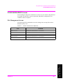
RX Level Test
CONFigure:SEQuence:LEVel <int>
CONFigure:SEQuence:LEVel?
This command defines whether or not to include RX Level tests in the test
sequence for the six measurements. <int> is a binary coded decimal ranging from 0
to 63 as follows:
bit 0 (1): For testing TCH1 or DCP1
bit 1 (2): For testing TCH2 or DCP2
bit 2 (4): For testing TCH3 or DCP3
bit 3 (8): For testing TCH4 or DCP4
bit 4 (16): For testing TCH5 or DCP5
bit 5 (32): For testing TCH6 or DCP6
The choices for each bit are 1 for Run and 0 for --- (skip). At preset, this is set to
63.
RX Quality Test
CONFigure:SEQuence:QUALity <int>
CONFigure:SEQuence:QUALity?
This command defines whether or not to include RX Quality tests in the test
sequence for the six measurements. <int> is a binary coded decimal ranging from 0
to 63 as follows:
bit 0 (1): For testing TCH1 or DCP1
bit 1 (2): For testing TCH2 or DCP2
bit 2 (4): For testing TCH3 or DCP3
bit 4 (16): For testing TCH5 or DCP5
bit 5 (32): For testing TCH6 or DCP6
The choices for each bit are 1 for Run and 0 for --- (skip). At preset, this is set to
63.
Sensitivity Test
CONFigure:SEQuence:SENSitivity <int>
CONFigure:SEQuence:SENSitivity?
This command defines whether or not to include Sensitivity tests in the test
sequence for the six measurements. <int> is a binary coded decimal ranging from 0
to 63 as follows:
bit 0 (1): For testing TCH1 or DCP1
Chapter 3
53
3. Programming Command
Reference
bit 3 (8): For testing TCH4 or DCP4
Programming Command Reference
CONFigure Subsystem
bit 1 (2): For testing TCH2 or DCP2
bit 2 (4): For testing TCH3 or DCP3
bit 3 (8): For testing TCH4 or DCP4
bit 4 (16): For testing TCH5 or DCP5
bit 5 (32): For testing TCH6 or DCP6
The choices for each bit are 1 for Run and 0 for --- (skip). At preset, this is set to
63.
Talk Test
CONFigure:SEQuence:SIGNaling:TALK ON|OFF|1|0
CONFigure:SEQuence:SIGNaling:TALK?
This command defines whether or not to include the Talk step in a test flow. The
choices are ON (1) for Run and OFF (0) for --- (skip). At preset, this is set to ON.
Talk Test TCH Channel
CONFigure:SEQuence:TCH:CHANnel <int>
CONFigure:SEQuence:TCH:CHANnel?
This command specifies the channel number of Traffic Channel for Talk tests
when Variable is set to TCH, for each radio standard set by the Radio Format
command. The allowable range and preset values are as follows:
RFORmat
Allowable Range
Preset Value
GSM900
1 to 124
1
E-GSM
0 to 124, 975 to 1023
1
DCS1800
512 to 885
512
PCS1900
512 to 810
512
Talk Test TCH Frequency
CONFigure:SEQuence:TCH:FREQuency
<real> [HZ|KHZ|MHZ|MAHZ]
CONFigure:SEQuence:TCH:FREQuency?
This command specifies the frequency of Traffic Channel for Talk tests when
Variable is set to TCH, for each radio standard set by the Radio Format command.
The allowable range and preset values are as follows:
54
Chapter 3
Programming Command Reference
CONFigure Subsystem
RFORmat
Allowable Range [Hz]
Preset Value [Hz]
GSM900
890200000 to 914800000
890200000
E-GSM
880200000 to 914800000
890200000
DCS1800
1710200000 to 1784800000
1710200000
PCS1900
1850200000 to 1909800000
1850200000
3. Programming Command
Reference
Chapter 3
55
Programming Command Reference
DISPlay Subsystem
DISPlay Subsystem
The DISPlay subsystem commands are used to select which of the Test Set’s
screens is being programmed. No query is available for these commands.
Command Reference for Initial Screen
Initial Screen
DISPlay:INITial
This command selects the initial screen for activating one of the function modes. A
test procedure can be selected from an SRAM memory card on this screen.
Command Reference for AUTOMATIC TEST Screens
Burst Timing/Power Ramp
DISPlay:AUTO:BTIMing
This command selects the Burst Timing/Power Ramp measurement screen for
AUTOMATIC TEST.
DC Current
DISPlay:AUTO:CURRent
This command selects the DC Current measurement screen for AUTOMATIC
TEST.
Peak TX Power
DISPlay:AUTO:TPOWer
This command selects the Peak TX Power measurement screen for AUTOMATIC
TEST.
Phase Error/Frequency Error
DISPlay:AUTO:PHASe
This command selects the Phase Error/Frequency Error measurement screen for
AUTOMATIC TEST.
Sensitivity/RX Quality/RX Level
DISPlay:AUTO:SENSitivity
This command selects the Sensitivity/RX Quality/RX Level measurement screen
for AUTOMATIC TEST.
56
Chapter 3
Programming Command Reference
DISPlay Subsystem
Stand-by
DISPlay:AUTO:STBY
This command selects the Stand-by screen for AUTOMATIC TEST.
Command Reference for CONFIGURATION Screens
File Management
DISPlay:CONFgiure:FILE
This command selects the File Management screen. The files including test setups
for all function modes are saved in and recalled or deleted from an SRAM memory
card. Also an SRAM memory card can be initialized.
System Configuration
DISPlay:CONFigure
This command selects the CONFIGURATION screen. The parameters and
controls on this screen set the fundamental information for all function modes of
the Test Set.
NOTE
“Serial Port” is not programmable but manually set.
Test Condition
DISPlay:CONDition
This command selects the Test Setup: Test Condition screen. The parameters and
controls on this screen set the test conditions for AUTOMATIC TEST and
MANUAL TEST.
DISPlay:SEQuence
This command selects the Test Setup: Test Sequence screen. The parameters and
controls on this screen set the test sequence for AUTOMATIC TEST.
Command Reference for MANUAL TEST Screens
DC Current
DISPlay:MANual:CURRent
This command selects the DC Current measuring screen for MANUAL TEST.
Measuring
DISPlay:MANual:MEASure
This command selects the Measuring screen for MANUAL TEST.
Chapter 3
57
3. Programming Command
Reference
Test Sequence
Programming Command Reference
DISPlay Subsystem
Peak TX Power/Burst Timing/Power Ramp
DISPlay:MANual:TPOWer
This command selects the Peak TX Power/Burst Timing/Power Ramp measuring
screen for MANUAL TEST.
NOTE
If Option 040 is installed and the mode is set to GPRS in
MANUAL TEST, this command selects the Peak TX Power/Power
vs Time screen.
Phase Error/Frequency Error
DISPlay:MANual:PHASe
This command selects the Phase Error/Frequency Error measuring screen for
MANUAL TEST.
Sensitivity/RX Quality/RX Level
DISPlay:MANual:SENSitivity
This command selects the Sensitivity/RX Quality/RX Level measuring screen for
MANUAL TEST.
NOTE
If Option 002 is installed and the mode is set to ASYNC in
MANUAL TEST, this command is invalid.
If Option 040 is installed and the mode is set to GPRS in
MANUAL TEST, this command selects the Sensitivity screen to
measure BLER.
Spectrum Monitor
DISPlay:MANual:SMONitor
This command selects the Spectrum Monitor measuring screen for MANUAL
TEST.
Stand-by
DISPlay:MANual:STBY
This command selects the Stand-by screen for MANUAL TEST.
NOTE
This command is valid only for Test Sets without any of Option 002
and Option 040.
Stand-by (Asynchronous Mode)
DISPlay:MANual:ASYN:STBY
This command selects the asynchronous mode Stand-by screen for MANUAL
TEST.
58
Chapter 3
Programming Command Reference
DISPlay Subsystem
NOTE
This command is valid only for Test Sets with Option 002.
Stand-by (GPRS Mode)
DISPlay:MANual:GPRS:STBY
This command selects the GPRS mode Stand-by screen for MANUAL TEST.
NOTE
This command is valid only for Test Sets with Option 040.
Stand-by (Synchronous Mode)
DISPlay:MANual:SYNC:STBY
This command selects the synchronous mode Stand-by screen for MANUAL
TEST.
NOTE
This command is valid only for Test Sets with any of Option 002
and Option 040.
Command Reference for SIGNAL GENERATOR Screen
RF Signal Generator
DISPlay:RFGenerator
This command selects the screen for SIGNAL GENERATOR.
NOTE
This command is valid only for Test Sets with Option 002.
Command Reference for SPECTRUM MONITOR Screen
3. Programming Command
Reference
Spectrum Monitor
DISPlay:SMONitor
This command selects the screen for SPECTRUM MONITOR.
NOTE
Chapter 3
This command is valid only for Test Sets with Option 002.
59
Programming Command Reference
HCOPy Subsystem
HCOPy Subsystem
The HCOPy commands are used to control the printing function.
HCOPy Subsystem Command Reference
Abort Printing
HCOPy:ABORt
This command stops to print. There is no query form of this command.
Print All Items
HCOPy:ITEM:ALL
This command executes to print the measured data and pass/fail results. There is
no query form of this command.
Dump Screen Image
HCOPy:SDUMp
This command executes to print a screen image. There is no query form of this
command.
60
Chapter 3
Programming Command Reference
RFGenerator Subsystem
RFGenerator Subsystem
The RFGenerator subsystem commands are used to set and read the controls and
parameters of the SIGNAL GENERATOR functions. Send the
"DISPlay:RFGenerator" command to display the SIGNAL GENERATOR screen
before sending the following commands.
NOTE
This section is applicable only for Test Sets with Option 002.
NOTE
For Test Sets with Option 002, the Radio Standard and Channel
settings done in this function are copied to SPECTRUM
MONITOR and vice versa.
RFGenerator Subsystem Command Reference
Amplitude
RFGenerator:AMPLitude <real> [DB]
RFGenerator:AMPLitude?
This command specifies an output amplitude of RF Level. The allowable range is
from −110.0 to −50.0 (dBm) in 0.5 steps. At preset, this is set to −50.0 (dBm).
DC Power Mode
RFGenerator:DCPower:MODE ON|OFF|1|0
RFGenerator:DCPower:MODE?
DC Power Voltage
RFGenerator:DCPower:VOLT <real> [V]
RFGenerator:DCPower:VOLT?
This command specifies a voltage value of DC Power. The allowable range is from
3.0 to 11.0 (V) in 0.1 steps. At preset, this is set to 3.0 (V).
Modulation Function
RFGenerator:MODulation OFF|PN9|ALL0
RFGenerator:MODulation?
This command defines a type of Modulation. The choices are OFF, PN9 and
ALL_0. At preset, this is set to OFF.
•
Chapter 3
If OFF is selected, the RF signal is a continuous wave.
61
3. Programming Command
Reference
This command defines a supply mode of DC Power. The choices are ON (1) and
OFF (0). If set to ON (1), DC Power is always supplied. If set to OFF (0), DC
Power is not supplied. At preset, this is set to OFF.
Programming Command Reference
RFGenerator Subsystem
•
If PN9 is selected, the RF signal is modulated by the 9-step pseudo-random
binary sequence code.
•
If ALL0 is selected, the RF signal is modulated by the all zero digital code.
Radio Standard
RFGenerator:RFORmat GSM900|E-GSM|DCS1800|PCS1900
RFGenerator:RFORmat?
This command defines a system of Radio Standard to be tested. The choices are
GSM900, E-GSM, DCS1800, and PCS1900. At preset, this is set to GSM900.
RF Signal Output Mode
RFGenerator:RFOUtput ON|OFF|1|0
RFGenerator:RFOUtput?
This command defines a mode of RF Output. The choices are ON (1) and OFF (0).
At preset, this is set to OFF.
Traffic Channel
RFGenerator:CHANnel <int>
RFGenerator:CHANnel?
This command specifies the channel number of Traffic Channel (TCH) for each
radio standard set by the Radio Format command. The allowable range and preset
values are as follows:
RFORmat
Allowable Range
Preset Value
GSM900
1 to 124
1
E-GSM
0 to 124, 975 to 1023
1
DCS1800
512 to 885
512
PCS1900
512 to 810
512
Traffic Channel Frequency
RFGenerator:FREQuency <real> [HZ|KHZ|MHZ|MAHZ]
RFGenerator:FREQuency?
This command specifies the frequency of Traffic Channel (TCH) for each radio
standard set by the Radio Format command. The allowable range and preset values
are as follows:
62
Chapter 3
Programming Command Reference
RFGenerator Subsystem
RFORmat
Allowable Range [Hz]
Preset Value [Hz]
GSM900
935200000 to 959800000
935200000
E-GSM
925200000 to 959800000
935200000
DCS1800
1805200000 to 1879800000
1805200000
PCS1900
1930200000 to 1989800000
1930200000
3. Programming Command
Reference
Chapter 3
63
Programming Command Reference
SMONitor Subsystem
SMONitor Subsystem
The SMONitor subsystem commands are used to set and read the controls and
parameters of the SPECTRUM MONITOR function. Send the
"DISPlay:SMONitor" command to display the SPECTRUM MONITOR screen
before sending the following commands.
NOTE
This section is applicable only for Test Sets with Option 002.
NOTE
For Test Sets with Option 002, the Radio Standard and Channel
settings done in this function are copied to SPECTRUM
MONITOR and vice versa.
SMONitor Subsystem Command Reference
Averaging Function
SMONitor:AVERage OFF|<int>
SMONitor:AVERage?
This command defines whether or not to activate the averaging function. The
choices are OFF and <int> for averaging time. The allowable range is from 2 to 99.
At preset, this is set to OFF.
DC Power Mode
SMONitor:DCPower:MODE ON|OFF|1|0
SMONitor:DCPower:MODE?
This command defines a supply mode of DC Power. The choices are ON (1) and
OFF (0). If set to ON (1), DC Power is always supplied. If set to OFF (0), DC
Power is not supplied. At preset, this is set to OFF.
DC Power Voltage
SMONitor:DCPower:VOLT <real> [V]
SMONitor:DCPower:VOLT?
This command specifies a voltage value of DC Power. The allowable range is from
3.0 to 11.0 (V) in 0.1 steps. At preset, this is set to 3.0 (V).
Display Span
SMONitor:SPAN 400k|100k
SMONitor:SPAN?
This command specifies a frequency bandwidth of Span. The choices are 400k for
the 0 to 400 kHz span, and 100k for the ±100 kHz span relative to the Traffic
Channel frequency. At preset, this is set to 400k.
64
Chapter 3
Programming Command Reference
SMONitor Subsystem
Marker Measurement
SMONitor:RESults:MARKer?
This query command returns a set of values, <string 1>, <string 2>,
<string 3>, <string 4>, and <string 5>, for the marker position.
•
<string 1> (1 digit) is 0 when all values are within the normal range, or 1 if any
measurement is overranged, underranged or not made.
•
The definitions and effective ranges of <string 2> (10 digits), <string 3> (5
digits), <string 4> (7 digits), and <string 5> (5 digits) are shown in the table
below. If any measurement is overranged, underranged or not made, the values
9999999999 for <string 2>, −99.9 for <string 3> and <string 5>, and +999999
for <string 4>, are returned.
Value
Definition
<string 2> Absolute RF frequency
[Hz]
Range: Span 0 to 400 kHz
Range: Span ±100 kHz
0880200000 to 0915200000,
1710200000 to 1785200000,
1850200000 to 1909800000
0880100000 to 0914900000,
1710100000 to 1784900000,
1850100000 to 1909500000
−99.9 to +99.9
−99.9 to +99.9
+000000 to +400000
−100000 to +100000
−99.9 to +0.00
−99.9 to +0.00
<string 3> Absolute RF level [dBm]
<string 4> Relative RF frequency [Hz]
<string 5> Relative RF level [dB]
Marker Position Control
SMONitor:RESults:MARKer:POINt UP|DOWN
SMONitor:RESults:MARKer:POINt <real> [HZ|KHZ|MHZ|MAHZ]
SMONitor:RESults:MARKer:POINt?
Measurement Range
SMONitor:RANGe −3DBM|+9DBM|+19DBM|+29DBM|+39DBM
SMONitor:RANGe?
This command specifies an absolute power level of Measurement Range. At
preset, this is set to +39DBM. The choices are as follows:
Chapter 3
•
−3DBM: The maximum input level is −3 dBm.
•
+9DBM: The maximum input level is +9 dBm.
•
+19DBM: The maximum input level is +19 dBm.
•
+29DBM: The maximum input level is +29 dBm.
65
3. Programming Command
Reference
This command allows you to move the marker UP or DOWN, or by a numeric
value <real>. The allowable range is from 0 to 400000 (Hz) for the 0 to 400 kHz
span, or from −100000 to +100000 (Hz) for the ±100 kHz span. At preset, this is
set to 1000 (Hz) if Span is set to 0 to 400 kHz, or 100 (Hz) if Span is set to ±100
kHz.
Programming Command Reference
SMONitor Subsystem
•
+39DBM: The maximum input level is +39 dBm.
Measurement Result
SMONitor:RESults?
•
If the 0 to 400 kHz span is selected, this query command returns a set of test
result values, <string 1>, <string 2>, <string 3>, <string 4>,
and <string 5>.
o <string 1> (1 digit) is 0 when all measured results are within normal range,
or 1 if any measurement is overranged, underranged or not made.
o The definitions and effective ranges of <string 2> (10 digits), <string 3> (5
digits), <string 4> (5 digits), and <string 5> (5 digits) are shown in the table
below. If any measurement is overranged, underranged or not made, the
values 9999999999 for <string 2> and −99.9 for <string 3>, <string 4> and
<string 5>, are returned.
•
If ±100 kHz is selected, this query command returns a set of test result values,
<string 1>, <string 2>, <string 3>, <string 4>,
<string 5>, and <string 6>.
o <string 1> (1 digit) is 0 when all measured results are within normal range,
or 1 if any measurement is overranged, underranged or not made.
o The definitions and effective ranges of <string 2> (10 digits), <string 3> (5
digits), <string 4> (5 digits), <string 5> (5 digits), and <string 6> (5 digits)
are shown in the table below. If any measurement is overranged,
underranged or not made, the values 99999999999 for <string 2> and −99.9
for <string 3>, <string 4>, <string 5> and <string 6> are returned.
Value
Definition
Range: Span 0 to 400 kHz
Range: Span ±100 kHz
0880200000 to 0915200000,
1710200000 to 1785200000,
1850200000 to 1909800000
0880100000 to 0914900000,
1710100000 to 1784900000,
1850100000 to 1909500000
<string 2>
Absolute peak
RF frequency [Hz]
<string 3>
Absolute peak
RF level [dBm]
−99.9 to +99.9
−99.9 to +99.9
<string 4>
Relative RF level [dB]
−99.9 to +00.0
(at +200 kHz)
−99.9 to +00.0
(at or close to +67.7 kHz)
<string 5>
Relative RF level [dB]
−99.9 to +00.0
(at +250 kHz)
−99.9 to +00.0
(at or close to ±0 kHz)
<string 6>
Relative RF level [dB]
<not applicable>
−99.9 to +00.0
(at or close to −67.7 kHz)
Radio Standard
SMONitor:RFORmat GSM900|E-GSM|DCS1800|PCS1900
SMONitor:RFORmat?
66
Chapter 3
Programming Command Reference
SMONitor Subsystem
This command defines a system of Radio Standard to be tested. The choices are
GSM900, E-GSM, DCS1800, and PCS1900. At preset, this is set to GSM900.
Resolution Bandwidth
SMONitor:RBWidth 10k|30k
SMONitor:RBWidth?
This command specifies a value of RBW (Resolution Bandwidth). The choices are
10k for 10 kHz and 30k for 30 kHz. At preset, this is set to 30k.
Traffic Channel
SMONitor:CHANnel <int>
SMONitor:CHANnel?
This command specifies the channel number of Traffic Channel to be analyzed for
each radio standard set by the Radio Format command. The allowable range and
preset values are as follows:
RFORmat
Allowable Range
Preset Value
GSM900
1 to 124
1
E-GSM
0 to 124, 975 to 1023
1
DCS1800
512 to 885
512
PCS1900
512 to 810
512
Traffic Channel Frequency
SMONitor:FREQuency <real> [HZ|KHZ|MHZ|MAHZ]
SMONitor:FREQuency?
Chapter 3
RFORmat
Allowable Range [Hz]
Preset Value [Hz]
GSM900
890200000 to 914800000
890200000
E-GSM
880200000 to 914800000
890200000
DCS1800
1710200000 to 1784800000
1710200000
PCS1900
1850200000 to 1909800000
1850200000
67
3. Programming Command
Reference
This command specifies the frequency of Traffic Channel to be analyzed for each
radio standard set by the Radio Format command. The allowable range and preset
values are as follows:
Programming Command Reference
SYSTem Subsystem
SYSTem Subsystem
The SYSTem commands are used to control the overall system function.
SYSTem Subsystem Command Reference
Lock System Panel
SYSTem:KLOCk ON|OFF|1|0
SYSTem:KLOCk?
This command locks the control panel functions for protection. At preset, this is set
to OFF (0).
If set to ON (1), all of the function modes become inactive, but only the Local
softkey is defined. By pressing the Local softkey or sending the commands
SYSTem:KLOCk OFF (0), the Test Set returns to the normal operation.
This command is not identical to the panel key lock in the CONFIGURATION
screen. See “Panel Key Control” on page 37.
Softkey Memory
SYSTem:MEMory:AMPLitude <real 1>,<real 2> [DBM]
SYSTem:MEMory:AMPLitude?
SYSTem:MEMory:CHANnel <int 1>,<int 2>
SYSTem:MEMory:CHANnel?
SYSTem:MEMory:PLEVel <int 1>,<int 2>
SYSTem:MEMory:PLEVel?
This command stores two settings of Amplitude, Channel, or Power Control Level
into Memory 1 and 2. The stored values are displayed on those softkeys.
System Error
SYSTem:ERRor?
This query command returns a set of values, <string 1> and <string 2>,
for error numbers and error messages. Refer to “Error Messages” on page 31 for
the listings of the error messages.
System Setup
SYSTem:SETup?
This query command returns a set of values, <string 1>,
<string 2>, ...., <string n>, for all of the Test Set settings.
SYSTem:SETup <string 1>,<string 2>,....,<string n>
68
Chapter 3
Programming Command Reference
SYSTem Subsystem
This command sets all of the Test Set settings at one time.
<string 1>, <string 2>, ...., <string n> must be the data which is
returned by the query command SYSTem:SETup?
3. Programming Command
Reference
Chapter 3
69
Programming Command Reference
TESTs Subsystem for AUTOMATIC TEST
TESTs Subsystem for AUTOMATIC TEST
This function allows to execute the overall measurements and pass/fail tests with
the automatic procedure. Test sequence and condition are configurable with the
CONFigure:SEQuence command and CONFigure:CONDition command.
NOTE
For Test Sets with Option 002, the DC Power voltage setting made
in this function are copied to the MANUAL TEST, SIGNAL
GENERATOR and SPECTRUM MONITOR and vice versa.
All Tests Results (Detail)
TESTs:AUTO:RESults:WHOLe?
This query command returns all of the test results values, <string 1>, <string 2>,
...., <string 186>, for AUTOMATIC TEST.
<string 1>, <string 2>, <string 3>, <string 4>, <string 5>:
Peak TX Power results (TCH1) - Refer to “Peak TX Power Measurement” on
page 75 for the meanings of each <string>.
<string 6>, <string 7>, <string 8>:
Burst Timing results (TCH1) - Refer to “Burst Timing Measurement” on page
72 for the meanings of each <string>.
<string 9>, <string 10>:
Power Ramp results (TCH1) - Refer to “Power Ramp Test” on page 74 for the
meanings of each <string>.
<string 11>, <string 12>, <string 13>, <string 14>:
Phase Error results (TCH1) - Refer to “Phase Error Marker Measurement” on
page 76 for the meanings of each <string>.
<string 15>, <string 16>, <string 17>:
Frequency Error results (TCH1) - Refer to “Frequency Error Measurement” on
page 76 for the meanings of each <string>.
<string 18>, <string 19>, <string 20>, <string 21>:
Sensitivity results (TCH1) - Refer to “Sensitivity Measurement” on page 79
for the meanings of each <string>.
<string 22>, <string 23>, <string 24>:
RX Quality results (TCH1) - Refer to “RX Quality Measurement” on page 78
for the meanings of each <string>.
<string 25>, <string 26>, <string 27>:
RX Level results (TCH1) - Refer to “RX Level Measurement” on page 78 for
the meanings of each <string>.
<string 28>, <string 29>, <string 30>, <string 31>:
70
Chapter 3
Programming Command Reference
TESTs Subsystem for AUTOMATIC TEST
DC Current results (TCH1) - Refer to “DC Current Measurement” on page 74
for the meanings of each <string>.
<string 32>, <string 33>, <string 34>, <string 35>, <string 36>:
Peak TX Power results (TCH2)
.....
.....
<string 183>, <string 184>, <string 185>, <string 186>:
DC Current results (TCH6)
All Tests Results (Summary)
TESTs:AUTO:RESults:ALL?
This query command returns a set of values, <string 1> and <string 2>,
that summarize the test results.
•
<string 1> is the 8-bit binary coded decimal ranging from 0 to 255 according to
the pass/fail results for all test flow steps. Each 8-bit binary coded decimal is
defined as follows:
bit 0 (1): LOC. Update
bit 1 (2): 1st Call
bit 2 (4): Talk
bit 3 (8): RF Test
bit 4 (16): 1st Release
bit 5 (32): 2nd Call
bit 7 (128): Measurement aborted
The choices for each bit are 1 for Fail and 0 for Pass or Skip.
•
<string 2> is a 10-bit binary coded decimal ranging from 0 to 1023 according to
the pass/fail results for all Test Items in the table. Each 10-bit binary coded
decimal is defined as follows:
bit 0 (1): Peak TX Power
bit 1 (2): Burst Timing
bit 2 (4): Power Ramp
bit 3 (8): Phase Error
bit 4 (16): Frequency Error
bit 5 (32): Sensitivity
bit 6 (64): RX Quality
Chapter 3
71
3. Programming Command
Reference
bit 6 (64): 2nd Release
Programming Command Reference
TESTs Subsystem for AUTOMATIC TEST
bit 7 (128): RX Level
bit 8 (256): DC Current
bit 9 (512): Test aborted
The choices for each bit are 1 for Fail and 0 for Pass or Skip.
If there are no test results nor pass/fail results, all bits are set to 1, resulting to
return the value 1023.
Command Reference for Burst Timing/Power Ramp Measurement Screen
Send the "DISPlay:AUTO:BTIMing" command to display the Burst
Timing/Power Ramp measurement screen for AUTOMATIC TEST before sending
the following commands.
Burst Timing Measurement
TESTs:AUTO:RESults:BTIMing1?
TESTs:AUTO:RESults:BTIMing2?
TESTs:AUTO:RESults:BTIMing3?
TESTs:AUTO:RESults:BTIMing4?
TESTs:AUTO:RESults:BTIMing5?
TESTs:AUTO:RESults:BTIMing6?
This query command returns a set of test result values, <string 1>, <string
2> and <string 3>, for each of the six measurements of Burst Timing.
•
<string 1> (1 digit) is 0 when all values are within the normal range, or 1 if any
measurement is overranged, underranged or not made.
•
<string 2> (1 digit) is the binary data, 0 or 1, for the pass (0) or fail (1) result.
•
<string 3> (4 digits) is the measured data ranging from −9.9 to +9.9 bits. If any
measurement is overranged, underranged or not made, the value −9.9 is
returned.
Power Ramp Graph Zoom
TESTs:AUTO:RESults:RAMP1:ZOOM ON|OFF|1|0
TESTs:AUTO:RESults:RAMP1:ZOOM?
TESTs:AUTO:RESults:RAMP2:ZOOM ON|OFF|1|0
TESTs:AUTO:RESults:RAMP2:ZOOM?
TESTs:AUTO:RESults:RAMP3:ZOOM ON|OFF|1|0
TESTs:AUTO:RESults:RAMP3:ZOOM?
TESTs:AUTO:RESults:RAMP4:ZOOM ON|OFF|1|0
TESTs:AUTO:RESults:RAMP4:ZOOM?
TESTs:AUTO:RESults:RAMP5:ZOOM ON|OFF|1|0
TESTs:AUTO:RESults:RAMP5:ZOOM?
72
Chapter 3
Programming Command Reference
TESTs Subsystem for AUTOMATIC TEST
TESTs:AUTO:RESults:RAMP6:ZOOM ON|OFF|1|0
TESTs:AUTO:RESults:RAMP6:ZOOM?
This command activates the zooming function of the Power Ramp graph for each
of the six measurements. The choices are ON (1) and OFF (0). If set to ON, the
rising and trailing edges are expanded. At preset, these are set to OFF.
Power Ramp Marker Measurement
TESTs:AUTO:RESults:RAMP1:MARKer?
TESTs:AUTO:RESults:RAMP2:MARKer?
TESTs:AUTO:RESults:RAMP3:MARKer?
TESTs:AUTO:RESults:RAMP4:MARKer?
TESTs:AUTO:RESults:RAMP5:MARKer?
TESTs:AUTO:RESults:RAMP6:MARKer?
This query command returns a set of marker position values, <string 1>,
<string 2>, <string 3> and <string 4>, in the Power Ramp graph for
each of the six measurements.
•
<string 1> (1 digit) is 0 when all values are within the normal range, or 1 if any
measurement is overranged, underranged or not made.
•
<string 2> (1 digit) is the binary data, 0 or 1, for the pass (0) or fail (1) result.
•
<string 3> (7 digits) is the marker position ranging from −009.25 to +156.25
(bits).
•
<string 4> (5 digits) is the power level of the marker position ranging from
−99.9 to +99.9 (dB). If any measurement is overranged, underranged or not
made, the value −99.9 is returned.
Power Ramp Marker Position Control
3. Programming Command
Reference
TESTs:AUTO:RESults:RAMP1:MARKer:POINt UP|DOWN
TESTs:AUTO:RESults:RAMP1:MARKer:POINt <real>
TESTs:AUTO:RESults:RAMP1:MARKer:POINt?
TESTs:AUTO:RESults:RAMP2:MARKer:POINt UP|DOWN
TESTs:AUTO:RESults:RAMP2:MARKer:POINt <real>
TESTs:AUTO:RESults:RAMP2:MARKer:POINt?
TESTs:AUTO:RESults:RAMP3:MARKer:POINt UP|DOWN
TESTs:AUTO:RESults:RAMP3:MARKer:POINt <real>
TESTs:AUTO:RESults:RAMP3:MARKer:POINt?
TESTs:AUTO:RESults:RAMP4:MARKer:POINt UP|DOWN
TESTs:AUTO:RESults:RAMP4:MARKer:POINt <real>
TESTs:AUTO:RESults:RAMP4:MARKer:POINt?
TESTs:AUTO:RESults:RAMP5:MARKer:POINt UP|DOWN
TESTs:AUTO:RESults:RAMP5:MARKer:POINt <real>
TESTs:AUTO:RESults:RAMP5:MARKer:POINt?
Chapter 3
73
Programming Command Reference
TESTs Subsystem for AUTOMATIC TEST
TESTs:AUTO:RESults:RAMP6:MARKer:POINt UP|DOWN
TESTs:AUTO:RESults:RAMP6:MARKer:POINt <real>
TESTs:AUTO:RESults:RAMP6:MARKer:POINt?
This command enables you to move the marker UP or DOWN in steps, or by
<real> bits ranging from −9.25 to +156.25 (bits) when the zoom function is set to
off, or from −8.0 to +2.0 (bits) and from 145.00 to +155.00 (bits) when the zoom
function is set to on, in the Power Ramp graph for each of the six measurements.
Power Ramp Test
TESTs:AUTO:RESults:RAMP1?
TESTs:AUTO:RESults:RAMP2?
TESTs:AUTO:RESults:RAMP3?
TESTs:AUTO:RESults:RAMP4?
TESTs:AUTO:RESults:RAMP5?
TESTs:AUTO:RESults:RAMP6?
This query command returns a set of test result values, <string 1> and
<string 2>, for each of the six measurements of Power Ramp.
•
<string 1> (1 digit) is 0 when all values are within the normal range, or 1 if any
measurement is overranged, underranged or not made.
•
<string 2> (1 digit) is the binary data, 0 or 1, for the pass (0) or fail (1) result.
Command Reference for DC Current Measurement Screen
Send the "DISPlay:AUTO:CURRent" command to display the DC Current
measurement screen for AUTOMATIC TEST before sending the following
commands.
DC Current Measurement
TESTs:AUTO:RESults:CURRent1?
TESTs:AUTO:RESults:CURRent2?
TESTs:AUTO:RESults:CURRent3?
TESTs:AUTO:RESults:CURRent4?
TESTs:AUTO:RESults:CURRent5?
TESTs:AUTO:RESults:CURRent6?
This query command returns a set of test result values, <string 1>,
<string 2>, <string 3> and <string 4>, for each of the six
measurements of DC Current .
•
<string 1> (1 digit) is 0 when all values are within the normal range, or 1 if any
measurement is overranged, underranged or not made.
•
<string 2> (1 digit) is the binary coded decimal for the pass/fail results as
follows:
bit 0 (1): Pass/Fail result for DC Current at Camp On
bit 1 (2): Pass/Fail result for DC Current at Talk
74
Chapter 3
Programming Command Reference
TESTs Subsystem for AUTOMATIC TEST
The choices for each bit are 1 for Fail and 0 for Pass.
•
<string 3> (5 digits) and <string 4> (5 digits) are the measured data ranging
from 0.000 to 1.000 (A) at Camp On and Talk. If any measurement is
overranged, underranged or not made, the value 2.5 (A) is returned.
Command Reference for MS Information
MS Information
TESTs:AUTO:RESults:MSINformation:IMSI?
This query command returns the IMSI string up to 15 letters.
TESTs:AUTO:RESults:MSINformation:IMEI?
This query command returns the IMEI string up to 15 letters.
TESTs:AUTO:RESults:MSINformation:DIAL?
This query command returns the dialed number string up to 20 digits.
TESTs:AUTO:RESults:MSINformation:PCLass?
This query command returns a 1-digit power class string value.
TESTs:AUTO:RESults:MSINformation:GVERsion?
This query command returns the 1-digit version number of GSM mobile under
test.
Command Reference for Peak TX Power Measurement Screen
Send the "DISPlay:AUTO:TPOWer" command to display the Peak TX Power
measurement screen for AUTOMATIC TEST before sending the following
commands.
TESTs:AUTO:RESults:TPOWer1?
TESTs:AUTO:RESults:TPOWer2?
TESTs:AUTO:RESults:TPOWer3?
TESTs:AUTO:RESults:TPOWer4?
TESTs:AUTO:RESults:TPOWer5?
TESTs:AUTO:RESults:TPOWer6?
These query commands return a set of test result values, <string 1>,
<string 2>, <string 3>, <string 4>, and <string 5>, for each of
the six measurements of Peak TX Power.
Chapter 3
•
<string 1> (1 digit) is 0 when all values are within the normal range, or 1 if any
measurement is overranged, underranged or not made.
•
<string 2> (1 digit) is the binary coded decimal ranging from 0 to 7 for the
pass/fail results as follows:
75
3. Programming Command
Reference
Peak TX Power Measurement
Programming Command Reference
TESTs Subsystem for AUTOMATIC TEST
bit 0 (1): Pass/Fail result for Peak TX Power High
bit 1 (2): Pass/Fail result for Peak TX Power Medium
bit 2 (4): Pass/Fail result for Peak TX Power Low
The choices for each bit are 1 for Fail and 0 for Pass.
•
<string 3> (5 digits), <string 4> (5 digits), and <string 5> (5 digits) are the
High, Medium, and Low ranges measured data ranging from −99.9 to + 99.9 in
dBm. If any measurement is overranged, underranged or not made, the value
−99.9 is returned.
Command Reference for Phase/Frequency Error Measurement Screen
Send the "DISPlay:AUTO:PHASe" command to display the Phase
Error/Frequency Error measurement screen for AUTOMATIC TEST before
sending the following commands.
Frequency Error Measurement
TESTs:AUTO:RESults:FREQuency1?
TESTs:AUTO:RESults:FREQuency2?
TESTs:AUTO:RESults:FREQuency3?
TESTs:AUTO:RESults:FREQuency4?
TESTs:AUTO:RESults:FREQuency5?
TESTs:AUTO:RESults:FREQuency6?
This query command returns a set of test result values, <string 1>, <string
2> and <string 3>, for each of the six measurements of Frequency Error.
•
<string 1> (1 digit) is 0 when all values are within the normal range, or 1 if any
measurement is overranged, underranged or not made.
•
<string 2> (1 digit) is the binary data, 0 or 1, for the pass (0) or fail (1) result.
•
<string 3> (5 digits) is the measured data ranging from −0999 to +0999 (Hz). If
any measurement is overranged, underranged or not made, the value +9999 is
returned.
Phase Error Marker Measurement
TESTs:AUTO:RESults:PHASe1:MARKer?
TESTs:AUTO:RESults:PHASe2:MARKer?
TESTs:AUTO:RESults:PHASe3:MARKer?
TESTs:AUTO:RESults:PHASe4:MARKer?
TESTs:AUTO:RESults:PHASe5:MARKer?
TESTs:AUTO:RESults:PHASe6:MARKer?
This query command returns a set of marker position values, <string 1>,
<string 2>, <string 3> and <string 4>, in the Phase Error graph for
each of the six measurements.
•
76
<string 1> (1 digit) is 0 when all values are within the normal range, or 1 if any
measurement is overranged, underranged or not made.
Chapter 3
Programming Command Reference
TESTs Subsystem for AUTOMATIC TEST
•
<string 2> (1 digit) is the binary data, 0 or 1, for the pass (0) or fail (1) result.
•
<string 3> (6 digits) is the marker position ranging from 000.00 to 147.00 in
bits.
•
<string 4> (5 digits) is the measured error ranging from −99.9 to +99.9 in °
(degree). If its measurement is overranged, underranged or not made, the value
+99.9 is returned.
Phase Error Marker Position Control
TESTs:AUTO:RESults:PHASe1:MARKer:POINt UP|DOWM
TESTs:AUTO:RESults:PHASe1:MARKer:POINt <real>
TESTs:AUTO:RESults:PHASe1:MARKer:POINt?
TESTs:AUTO:RESults:PHASe2:MARKer:POINt UP|DOWN
TESTs:AUTO:RESults:PHASe2:MARKer:POINt <real>
TESTs:AUTO:RESults:PHASe2:MARKer:POINt?
TESTs:AUTO:RESults:PHASe3:MARKer:POINt UP|DOWN
TESTs:AUTO:RESults:PHASe3:MARKer:POINt <real>
TESTs:AUTO:RESults:PHASe3:MARKer:POINt?
TESTs:AUTO:RESults:PHASe4:MARKer:POINt UP|DOWM
TESTs:AUTO:RESults:PHASe4:MARKer:POINt <real>
TESTs:AUTO:RESults:PHASe4:MARKer:POINt?
TESTs:AUTO:RESults:PHASe5:MARKer:POINt UP|DOWN
TESTs:AUTO:RESults:PHASe5:MARKer:POINt <real>
TESTs:AUTO:RESults:PHASe5:MARKer:POINt?
TESTs:AUTO:RESults:PHASe6:MARKer:POINt UP|DOWN
TESTs:AUTO:RESults:PHASe6:MARKer:POINt <real>
TESTs:AUTO:RESults:PHASe6:MARKer:POINt?
Phase Error Measurement
TESTs:AUTO:RESults:PHASe1?
TESTs:AUTO:RESults:PHASe2?
TESTs:AUTO:RESults:PHASe3?
TESTs:AUTO:RESults:PHASe4?
TESTs:AUTO:RESults:PHASe5?
TESTs:AUTO:RESults:PHASe6?
This query command returns a set of test result values, <string 1>,
<string 2>, <string 3>, and <string 4>, for each of the six
measurements of Peak and RMS Phase Error.
•
Chapter 3
<string 1> (1 digit) is 0 when all values are within the normal range, or 1 if any
measurement is overranged, underranged or not made.
77
3. Programming Command
Reference
This command enables you to move the marker UP or DOWN in steps, or by
<real> bits ranging from 0.0 to 147.0 bits, in the Phase Error graph for each of the
six measurements. At preset, these are set to 0.25 (bits).
Programming Command Reference
TESTs Subsystem for AUTOMATIC TEST
•
<string 2> (1 digit) is the binary coded decimal ranging from 0 to 3 for the
pass/fail results as follows:
bit 0 (1): Pass/Fail result for RMS Phase Error
bit 1 (2): Pass/Fail result for Peak Phase Error
The choices for each bit are 1 for Fail and 0 for Pass.
•
<string 3> (4 digits) and <string 4> (4 digits) are the measured rms/peak error
data ranging from 00.0 to 99.9 in ° (degrees). If any measurement is
overranged, underranged or not made, the value 99.9 is returned.
Command Reference for Sensitivity/RX Quality/RX Level Measurement
Screen
Send the "DISPlay:AUTO:SENSitivity" command to display the Sensitivity/RX
Quality/RX Level screen for AUTOMATIC TEST before sending the following
commands.
RX Level Measurement
TESTs:AUTO:RESults:LEVel1?
TESTs:AUTO:RESults:LEVel2?
TESTs:AUTO:RESults:LEVel3?
TESTs:AUTO:RESults:LEVel4?
TESTs:AUTO:RESults:LEVel5?
TESTs:AUTO:RESults:LEVel6?
This query command returns a set of test result values, <string 1>, <string
2> and <string 3>, for each of the six measurements of RX Level.
•
<string 1> (1 digit) is 0 when all values are within the normal range, or 1 if any
measurement is overranged, underranged or not made.
•
<string 2> (1 digit) is the binary data, 0 or 1, for the pass (0) or fail (1) result.
•
<string 3> (2 digits) is the measured data corresponding to one of the RX Level
factors as follows:
Factor:
RX Level: [dBm]
00
01
...
62
63
<−110
−110 to −109
...
−49 to −48
>−48
If any measurement is overranged, underranged or not made, the value 63 is
returned.
RX Quality Measurement
TESTs:AUTO:RESults:QUALity1?
TESTs:AUTO:RESults:QUALity2?
TESTs:AUTO:RESults:QUALity3?
78
Chapter 3
Programming Command Reference
TESTs Subsystem for AUTOMATIC TEST
TESTs:AUTO:RESults:QUALity4?
TESTs:AUTO:RESults:QUALity5?
TESTs:AUTO:RESults:QUALity6?
This query command returns a set of test result values, <string 1>, <string
2> and <string 3>, for each of the six measurements of RX Quality.
•
<string 1> (1 digit) is 0 when all values are within the normal range, or 1 if any
measurement is overranged, underranged or not made.
•
<string 2> (1 digit) is the binary data, 0 or 1, for the pass (0) or fail (1) result.
•
<string 3> (1 digit) is the measured data corresponding to one of the RX
Quality factors as follows:
Factor:
RX Quality: [%]
0
1
...
6
7
<0.2
0.2 to 0.4
...
6.4 to 12.8
>12.8
If any measurement is overranged, underranged or not made, the value 7 is
returned.
Sensitivity Measurement
TESTs:AUTO:RESults:SENSitivity1?
TESTs:AUTO:RESults:SENSitivity2?
TESTs:AUTO:RESults:SENSitivity3?
TESTs:AUTO:RESults:SENSitivity4?
TESTs:AUTO:RESults:SENSitivity5?
TESTs:AUTO:RESults:SENSitivity6?
This query command returns a set of test result values, <string 1>,
<string 2>, <string 3> and <string 4>, for each of the six
measurements of Sensitivity.
<string 1> (1 digit) is 0 when all values are within the normal range, or 1 if any
measurement is overranged, underranged or not made.
•
<string 2> (1 digit) is the binary coded decimal ranging from 0 to 3 for the
pass/fail results as follows:
bit 0 (1): Pass/Fail result for Sensitivity BER (bit error rate)
bit 1 (2): Pass/Fail result for Sensitivity FER (frame error rate)
The choices for each bit are 1 for Fail and 0 for Pass.
•
Chapter 3
<string 3> (5 digits) and <string 4> (5 digits) are the measured BER and FER
data ranging from 00.00 to 99.99 in %. If any measurement is overranged,
underranged or not made, the value 99.99 is returned.
79
3. Programming Command
Reference
•
Programming Command Reference
TESTs Subsystem for AUTOMATIC TEST
Command Reference for Stand-by/Measuring Screens
The following commands are used to set the controls and parameters associated
with the initial test condition for the Stand-by/Measuring screens. The query
commands return the settings of those controls and parameters.
Send the "DISPlay:AUTO:STBY" command to display the AUTOMATIC TEST:
Stand-by screen before sending the following commands.
6 Measurement DCP Variable
TESTs:AUTO:VARiable:DCP:VOLT1 <real> [V]
TESTs:AUTO:VARiable:DCP:VOLT1?
TESTs:AUTO:VARiable:DCP:VOLT2 <real> [V]
TESTs:AUTO:VARiable:DCP:VOLT2?
TESTs:AUTO:VARiable:DCP:VOLT3 <real> [V]
TESTs:AUTO:VARiable:DCP:VOLT3?
TESTs:AUTO:VARiable:DCP:VOLT4 <real> [V]
TESTs:AUTO:VARiable:DCP:VOLT4?
TESTs:AUTO:VARiable:DCP:VOLT5 <real> [V]
TESTs:AUTO:VARiable:DCP:VOLT5?
TESTs:AUTO:VARiable:DCP:VOLT6 <real> [V]
TESTs:AUTO:VARiable:DCP:VOLT6?
These commands set the Variable field to DC Power and specify the six voltage
values at which the six measurements are to be made. These measurements are
made at one fixed traffic channel. The allowable range is from 3.0 to 11.0 (V) in
0.1 steps. The value 99.9 causes the DCP test to be skipped (---- shown in the table
cell). At preset, these are set to 3.0 (V).
6 Measurement TCH Variable
TESTs:AUTO:VARiable:TCH:CHANnel1 <int>
TESTs:AUTO:VARiable:TCH:CHANnel1?
TESTs:AUTO:VARiable:TCH:CHANnel2 <int>
TESTs:AUTO:VARiable:TCH:CHANnel2?
TESTs:AUTO:VARiable:TCH:CHANnel3 <int>
TESTs:AUTO:VARiable:TCH:CHANnel3?
TESTs:AUTO:VARiable:TCH:CHANnel4 <int>
TESTs:AUTO:VARiable:TCH:CHANnel4?
TESTs:AUTO:VARiable:TCH:CHANnel5 <int>
TESTs:AUTO:VARiable:TCH:CHANnel5?
TESTs:AUTO:VARiable:TCH:CHANnel6 <int>
TESTs:AUTO:VARiable:TCH:CHANnel6?
80
Chapter 3
Programming Command Reference
TESTs Subsystem for AUTOMATIC TEST
These commands set the Variable field to TCH (Traffic Channel) and specify the
six channel numbers at which the six measurements are to be made, for each of the
radio standards in conjunction with the Multi Band settings. These measurements
are made at one fixed voltage of DC Power. The value 9999 causes the TCH test to
be skipped (---- shown in the table cell). The allowable range and preset values are
as follows:
RFORmat
MBANd
Allowable Range
Preset Value
1 to 124;
512 to 885
1, 62, 124
DCS1800
OFF
1 to 124
DCS1800
0 to 124|975 to 1023;
512 to 885
OFF
0 to 124|975 to 1023
GSM900
512 to 885;
1 to 124
E-GSM
512 to 885;
0 to 124|975 to 1023
OFF
512 to 885
OFF
512 to 810
GSM900
E-GSM
DCS1800
PCS1900
1, 62, 124
512, 699, 885
512, 661, 810
BCCH
TESTs:AUTO:BCCH <int>
TESTs:AUTO:BCCH?
RFORmat
Allowable Range
Preset Value
GSM900
1 to 124
20
E-GSM
0 to 124, 975 to 1023
20
DCS1800
512 to 885
698
PCS1900
512 to 810
698
DC Power Mode
TESTs:AUTO:DCPower:MODE AUTO|ON|OFF
TESTs:AUTO:DCPower:MODE?
This command defines a supply mode of DC Power. The choices are AUTO, ON,
and OFF. At preset, this is set to OFF.
Chapter 3
81
3. Programming Command
Reference
This command specifies the number of Broadcast Control Channel for each radio
standard set by the Radio Format commands. The allowable range and preset
values are as follows:
Programming Command Reference
TESTs Subsystem for AUTOMATIC TEST
•
If set to AUTO, DC Power is supplied during a measurement cycle or until a
measurement is aborted.
•
If set to ON, DC Power is always supplied.
•
If set to OFF, DC Power is not supplied and the variable of the six
measurements is automatically set to TCH.
DC Power Voltage
TESTs:AUTO:DCPower:VOLT <real> [V]
TESTs:AUTO:DCPower:VOLT?
This command specifies a voltage value of DC Power. The allowable range is from
3.0 to 11.0 (V) in 0.1 steps. At preset, this is set to 3.0 (V).
Multi Band
TESTs:AUTO:MBANd DCS1800|OFF
TESTs:AUTO:MBANd?
This command specifies whether or not to include the multi-band mobile tests for
DCS1800 when GSM900 or E-GSM is specified by the Radio Format command.
TESTs:AUTO:MBANd GSM900|E-GSM|OFF
TESTs:AUTO:MBANd?
This command specifies whether or not to include the multi-band mobile tests for
GSM900 or E-GSM when DCS1800 is specified by the Radio Format command.
If PCS1900 is specified with the Radio Format command, the Multi Band
command is automatically disabled (set to OFF).
Radio Standard
TESTs:AUTO:RFORmat GSM900|E-GSM|DCS1800|PCS1900
TESTs:AUTO:RFORmat?
This command defines a system of Radio Standard to be tested. The choices are
GSM900, E-GSM, DCS1800, and PCS1900. If PCS1900 is selected, the Multi
Band command is automatically set to OFF. At preset, this is set to GSM900.
Screen Mode
TESTs:AUTO:SCReen SIMPlified|DETailed
This command selects the screen mode. The choices are SIMPlified screen and the
DETailed screen. At preset, this value is set to SIMP.
Signaling State
TESTs:AUTO:MEASure:SIGNaling:STATe?
This query command returns a 9-bit binary coded decimal corresponding to the test
flow steps executed for a test cycle as follows:
bit 0 (1): LOC. Update
82
Chapter 3
Programming Command Reference
TESTs Subsystem for AUTOMATIC TEST
bit 1 (2): 1st Call
bit 2 (4): Talk
bit 3 (8): RF Test
bit 4 (16): 1st Release
bit 5 (32): 2nd Call
bit 6 (64): 2nd Release
bit 7 (128): Measurement end with test result
bit 8 (256): Measurement end without test result (Aborted or Time out error
occurred)
Talk Test Result
TESTs:AUTO:MEASure:TALK PASS|FAIL
This command verifies whether the test result of the Talk step passes or fails. The
choices are PASS and FAIL. There is no query form of this command.
Talk Test TCH
TESTs:AUTO:TCH <int>
TESTs:AUTO:TCH?
This command specifies the channel number of Traffic Channel for Talk tests, for
each radio standard set by the Radio Format command. The allowable range and
preset values are as follows:
Allowable Range
Preset Value
GSM900
1 to 124
1
E-GSM
0 to 124, 975 to 1023
1
DCS1800
512 to 885
512
PCS1900
512 to 810
512
3. Programming Command
Reference
Chapter 3
RFORmat
83
Programming Command Reference
TESTs Subsystem for MANUAL TEST
TESTs Subsystem for MANUAL TEST
This function allows you to execute real time measurements. Depending on the
combination of the options installed with the Test Set, the different measurement
modes are available as follows:
Option
Available Measurement Mode
<none>
SYNC (Synchronous)
002
SYNC, ASYNC (Asynchronous)
040
SYNC, GPRS
002, 040
SYNC, ASYNC, GPRS
NOTE
For Test Sets with Option 002, the DC Power voltage setting done
in this function are copied to the AUTOMATIC TEST, SIGNAL
GENERATOR and SPECTRUM MONITOR and vice versa.
Command Reference for DC Current Measurement Screen
The Current commands are used to set the controls and parameters associated with
the DC Current measurements and the pass/fail tests.
Send the "DISPlay:MANual:CURRent" command to display the DC Current
measurement screen for MANUAL TEST before sending the following
commands.
DC Current Measurement (ASYNC or GPRS mode)
TESTs:MANual:CURRent:RESults?
This query command returns a set of test result values, <string 1>,
<string 2> and <string 3>, for asynchronous or GPRS mode tests of DC
Current (without titling Camp On nor Talk).
•
<string 1> (1 digit) is 0 when all values are within the normal range, or 1 if any
measurement is overranged, underranged or not made.
•
<string 2> (1 digit) is the binary data, 0 or 1, for the pass (0) or fail (1) result
using the low and high limits for Talk.
•
<string 3> (5 digits) is the measured dc current data ranging from 0.000 to
1.000 (A). If any measurement is overranged, underranged or not made, the
value 2.500 is returned.
NOTE
84
This command is valid only for Test Sets with Option 002 and
Option 040.
Chapter 3
Programming Command Reference
TESTs Subsystem for MANUAL TEST
DC Current Measurement at Camp On
TESTs:MANual:CURRent:RESults:CAMP?
This query command returns a set of test result values, <string 1>,
<string 2>, <string 3>, and <string 4>, for synchronous mode Camp
On tests of DC Current.
•
<string 1> (1 digit) is 0 when all values are within the normal range, or 1 if any
measurement is overranged, underranged or not made.
•
<string 2> (1 digit) is the binary data, 0 or 1, for the pass (0) or fail (1) result
using the low and high limits for Camp On.
•
<string 3> (5 digits) and <string 4> (5 digits) are the measured dc current data
ranging from 0.000 to 1.000 (A). If any measurement is overranged,
underranged or not made, the value 2.500 is returned.
NOTE
This command is valid if the mode is set to SYNC.
DC Current Measurement at Talk
TESTs:MANual:CURRent:RESults:TALK?
This query command returns a set of test result values, <string 1>,
<string 2>, <string 3>, and <string 4>, for synchronous mode Talk
tests of DC Current.
<string 1> (1 digit) is 0 when all values are within the normal range, or 1 if any
measurement is overranged, underranged or not made.
•
<string 2> (1 digit) is the binary data, 0 or 1, for the pass (0) or fail (1) result
using the low and high limits for Talk.
•
<string 3> (5 digits) and <string 4> (5 digits) are the measured current data
ranging from 0.000 to 1.000 (A). If any measurement is overranged,
underranged or not made, the value 2.500 is returned.
NOTE
This command is valid if the mode is set to SYNC.
DC Power Voltage
TESTs:MANual:CURRent:DCPower:VOLT <real> [V]
TESTs:MANual:CURRent:DCPower:VOLT?
This command specifies a voltage value of DC Power when the DC Power supply
mode in the Stand-by screen is set to ON. The allowable range is from 3.0 to 11.0
(V) in 0.1 steps. At preset, this is set to 3.0 (V).
Power Control Level
TESTs:MANual:CURRent:PLEVel <int>
TESTs:MANual:CURRent:PLEVel?
Chapter 3
85
3. Programming Command
Reference
•
Programming Command Reference
TESTs Subsystem for MANUAL TEST
This command specifies a value of Power Control Level for each radio standard set
by the Radio Format command. The allowable range and preset values are as
follows:
RFORmat
Allowable Range
Preset Value
GSM900
2 (+39 dBm) to 19 (+5 dBm)
5 (+33 dBm)
E-GSM
2 (+39 dBm) to 19 (+5 dBm)
5 (+33 dBm)
DCS1800
0 (+30 dBm) to 15 (+0 dBm), or
29 (+36 dBm) to 31 (+32 dBm)
0 (+30 dBm)
PCS1900
0 (+30 dBm) to 15 (+0 dBm), or
30 (+33 dBm) to 31 (+32 dBm)
0 (+30 dBm)
Traffic Channel
TESTs:MANual:CURRent:CHANnel <int>
TESTs:MANual:CURRent:CHANnel?
This command specifies the channel number of Traffic Channel for each of the
radio standards in conjunction with the Multi Band settings. The allowable range
and preset values are as follows:
RFORmat
MBANd
Allowable Range
Preset Value
1 to 124;
512 to 885
1
DCS1800
OFF
1 to 124
DCS1800
0 to 124|975 to 1023;
512 to 885
OFF
0 to 124|975 to 1023
GSM900
512 to 885;
1 to 124
E-GSM
512 to 885;
975 to 1023|0 to 124
OFF
512 to 885
OFF
512 to 810
GSM900
E-GSM
DCS1800
PCS1900
1
512
512
Traffic Channel Frequency
TESTs:MANual:CURRent:FREQuency
<real> [HZ|KHZ|MHZ|MAHZ]
TESTs:MANual:CURRent:FREQuency?
86
Chapter 3
Programming Command Reference
TESTs Subsystem for MANUAL TEST
This command specifies the frequency of Traffic Channel for each of the radio
standards in conjunction with the Multi Band settings. The allowable range and
preset values are as follows:
RFORmat
MBANd
Allowable Range [Hz]
Preset Value [Hz]
890200000 to 914800000;
1710200000 to 1784800000
896000000
DCS1800
OFF
890200000 to 914800000
DCS1800
880200000 to 914800000;
1710200000 to 1784800000
OFF
880200000 to 914800000
GSM900
1710200000 to 1784800000;
890200000 to 914800000
E-GSM
1710200000 to 1784800000;
880200000 to 914800000
OFF
1710200000 to 1784800000
OFF
1850200000 to 1909800000
GSM900
E-GSM
DCS1800
PCS1900
896000000
1710200000
1850200000
Command Reference for Measuring Screens
These commands are used to set the controls and parameters associated with an
initial test condition.
Send the "DISPlay:MANual:MEASure" command to display the Measuring for
MANUAL TEST before sending the following commands.
TESTs:MANual:MEASure:BSCall
This command executes a call setup to the mobile from the Test Set. There is no
query form of this command.
NOTE
If Option 002 and Option 040 are installed and the mode is set to
ASYNC or GPRS, this command is invalid.
BS Level
TESTs:MANual:MEASure:AMPLitude <real> [dBm]
TESTs:MANual:MEASure:AMPLitude?
This command specifies an amplitude of BS Level in the Measuring screen. The
allowable range is from −110.0 to −50.0 (dBm) in 0.5 steps. At preset, this is set to
−50.0 (dBm).
Chapter 3
87
3. Programming Command
Reference
BS Call
Programming Command Reference
TESTs Subsystem for MANUAL TEST
BS Release
TESTs:MANual:MEASure:BSRelease
This command releases the mobile from the Test Set. There is no query form of
this command.
NOTE
If Option 002 and Option 040 are installed and the mode is set to
ASYNC or GPRS, this command is invalid.
DC Power Voltage
TESTs:MANual:MEASure:DCPower:VOLT <real> [V]
TESTs:MANual:MEASure:DCPower:VOLT?
This command specifies a voltage value of DC Power if the DC Power supply
mode in the Stand-by screen is set to ON. The allowable range is from 3.0 to 11.0
(V) in 0.1 steps. At preset, this is set to 3.0 (V).
GPRS Test End
TESTs:MANual:MEASure:END
This command terminates measurements in the GPRS mode and returns to the
Stand-by screen. There is no query form of this command.
NOTE
If the mode is set to SYNC on the Test Set with Option 040, this
command is invalid.
Midamble
TESTs:MANual:MEASure:MIDamble
NONE|TSC0|TSC1|TSC2|TSC3|TSC4|TSC5|TSC6|TSC7
TESTs:MANual:MEASure:MIDamble?
This command specifies a value of Training Sequence Code (TSC), TSC0 to
TSC7, or NONE for the amplitude trigger. At preset, this is set to TSC5.
NOTE
For Test Sets without Option 002, or if the mode is set to SYNC,
this command is invalid.
For Test Sets with Option 040, if the mode is set to GPRS, this
command is invalid.
MS Call
TESTs:MANual:MEASure:MSCall
This command executes a call from the mobile. There is no query form of this
command.
88
Chapter 3
Programming Command Reference
TESTs Subsystem for MANUAL TEST
NOTE
For Test Sets with Option 002, if the mode is set to ASYNC, this
command is invalid.
For Test Sets with Option 040, if the mode is set to GPRS, this
command is invalid.
MS Release
TESTs:MANual:MEASure:MSRelease
This command executes a release from the mobile. There is no query form of this
command.
NOTE
For Test Sets with Option 002, if the mode is set to ASYNC, this
command is invalid.
For Test Sets with Option 040, if the mode is set to GPRS, this
command is invalid.
MS Signal
TESTs:MANual:MEASure:SIGNal BURST|CW
TESTs:MANual:MEASure:SIGNal?
For Test Sets with Option 002, this command defines a signaling type from the
mobile when in the asynchronous mode. The choices are BURST and CW. At
preset, this is set to BURST.
NOTE
For Test Sets without Option 002, this is fixed to Burst.
Power Control Level
This command specifies a value of Power Control Level for each radio standard set
by the Radio Format command. The allowable range and preset values are as
follows:
Chapter 3
RFORmat
Allowable Range
Preset Value
GSM900
2 (+39 dBm) to 19 (+5 dBm)
5 (+33 dBm)
E-GSM
2 (+39 dBm) to 19 (+5 dBm)
5 (+33 dBm)
DCS1800
0 (+30 dBm) to 15 (+0 dBm), or
29 (+36 dBm) to 31 (+32 dBm)
0 (+30 dBm)
PCS1900
0 (+30 dBm) to 15 (+0 dBm), or
30 (+33 dBm) to 31 (+32 dBm)
0 (+30 dBm)
89
3. Programming Command
Reference
TESTs:MANual:MEASure:PLEVel <int>
TESTs:MANual:MEASure:PLEVel?
Programming Command Reference
TESTs Subsystem for MANUAL TEST
Signaling State (GPRS mode)
TESTs:MANual:MEASure:SIGNaling:STATe?
This query command returns a value, <string>, corresponding to the test flow
steps executed for a test cycle for the GPRS mode as follows:
bit 0 (1): Idle
bit 1 (2): Attached
bit 2 (4): Connect
bit 3 (8): Time Out Error
bit 4 (16): Measurement End
The choices for each bit are 1 for executed and 0 for not.
NOTE
If the mode is set to SYNC on the Test Set with Option 040, this
command is invalid.
Signaling State (SYNC mode)
TESTs:MANual:MEASure:SIGNaling:STATe?
This query command returns a value, <string>, corresponding to the test flow
steps executed for a test cycle as follows:
bit 0 (1): MS Call/BS Call
bit 1 (2): Talk/RF Test
bit 2 (4): MS Release/BS Release
bit 3 (8): Time Out Error
bit 4 (16): Measurement End
The choices for each bit are 1 for executed and 0 for not.
NOTE
For Test Sets with Option 002, if the mode is set to ASYNC, this
command is invalid.
If the mode is set to GPRS on the Test Set with Option 040, this
command is invalid.
Slot Configuration
TESTs:MANual:MEASure:SCONfigure 1×1|2×1
This command specifies the slot combination for downlink and uplink,
respectively, in the Measuring screen for the GPRS mode, in conjunction with the
Slot Measured setting. The combinations of the slot configuration and the slot
order measured are as follows:
90
Chapter 3
Programming Command Reference
TESTs Subsystem for MANUAL TEST
Option
Slot Configuration
Slot Order Measured
040
Downlink 1 × Uplink 1
4
040
2×1
4
At preset, this is set to 1 × 1.
If the mode is set to GPRS on the Test Set with Option 040, this
command is valid.
NOTE
Slot Measured
TESTs:MANual:MEASure:MSLot 4
This command specifies the order of slot to be measured, in the Measuring screen
for the GPRS mode, in conjunction with the Slot Configuration setting. The
combinations of the slot order measured and the slot configuration are as follows:
Option
Slot
Configuration
Slot Order Measured
040
D1×U1
4 (fourth)
040
2×1
4 (fourth)
At preset, this is set to 4.
NOTE
Timing Advance
TESTs:MANual:MEASure:TADVance <integer>
TESTs:MANual:MEASure:TADVance?
This command specifies the number of bits for Timing Advance. The allowable
range is from 0 to 63 (bits).
NOTE
For Test Sets with Option 002, if the mode is set to SYNC, this
command is valid.
For Test Sets with Option 002 and Option 040, if the mode is set to
SYNC or GPRS, this command is valid.
Chapter 3
91
3. Programming Command
Reference
As the slot order measured is fixed to 4 when the mode is set to
GPRS on the Test Set with Option 040, this command is invalid.
Programming Command Reference
TESTs Subsystem for MANUAL TEST
Traffic Channel
TESTs:MANual:MEASure:TCH:CHANnel <int>
TESTs:MANual:MEASure:TCH:CHANnel?
This command specifies the channel number of Traffic Channel (TCH) to be tested
for each of the radio standards in conjunction with the Multi Band settings. The
allowable range and preset values are as follows:
RFORmat
MBANd
Allowable Range
Preset Value
GSM900
DCS1800
1 to 124;
512 to 885
1
OFF
1 to 124
DCS1800
0 to 124|975 to 1023;
512 to 885
OFF
0 to 124|975 to 1023
GSM900
512 to 885;
1 to 124
E-GSM
512 to 885;
975 to 1023|0 to 124
OFF
512 to 885
OFF
512 to 810
E-GSM
DCS1800
PCS1900
1
512
512
Traffic Channel Frequency
TESTs:MANual:TCH:FREQuency <real> [HZ|KHZ|MHZ|MAHZ]
TESTs:MANual:TCH:FREQuency?
This command specifies the frequency of Traffic Channel (TCH) to be tested, for
each of the radio standards in conjunction with the Multi Band settings. The
allowable range and preset values are as follows:
RFORmat
MBANd
Allowable Range [Hz]
Preset Value [Hz]
GSM900
DCS1800
890200000 to 914800000;
1710200000 to 1784800000
896000000
OFF
890200000 to 914800000
DCS1800
880200000 to 914800000;
1710200000 to 1784800000
OFF
880200000 to 914800000
E-GSM
92
896000000
Chapter 3
Programming Command Reference
TESTs Subsystem for MANUAL TEST
RFORmat
MBANd
Allowable Range [Hz]
Preset Value [Hz]
DCS1800
GSM900
1710200000 to 1784800000;
890200000 to 914800000
1710200000
E-GSM
1710200000 to 1784800000;
880200000 to 914800000
OFF
1710200000 to 1784800000
OFF
1850200000 to 1909800000
PCS1900
1850200000
Command Reference for MS Information
MS Information
TESTs:MANual:RESults:MSINformation:IMSI?
This query command returns the IMSI string of 15 letters.
TESTs:MANual:RESults:MSINformation:IMEI?
This query command returns the IMEI string of 15 letters.
TESTs:MANual:RESults:MSINformation:DIAL?
This query command returns the 20-digit dialed number string.
TESTs:MANual:RESults:MSINformation:PCLass?
This query command returns a 1-digit power class string.
TESTs:MANual:RESults:MSINformation:GVERsion?
This query command returns a 1-digit version number of the GSM mobile under
test.
For Test Sets with Option 002, if the mode is set to ASYNC, these
commands are invalid.
For Test Sets with Option 040, if the mode is set to GPRS, the
commands for DIAL and GVERsion are invalid.
Command Reference for Peak TX Power /Burst Timing/Power Ramp
Measurement Screen
The TPOWer and TXAMplitude commands are used to set or read the controls and
parameters associated with the Peak TX Power/Burst Timing/Power Ramp
measurements and the pass/fail tests.
Send the "DISPlay:MANual:TPOWer" command to display the Peak TX
Power/Burst Timing/Power Ramp screen for MANUAL TEST before sending the
following commands.
Chapter 3
93
3. Programming Command
Reference
NOTE
Programming Command Reference
TESTs Subsystem for MANUAL TEST
NOTE
For Test Sets with Option 040, if the mode is set to GPRS, this
measurement screen is titled as Peak TX Power/Power vs Time.
Actual Timing Advance
TESTs:MANual:TXAMplitude:ACTAdvance?
This command queries the value of Actual Timing Advance.
NOTE
For Test Sets with Option 002, if the mode is set to SYNC, this
command is valid.
For Test Sets with Option 002 and Option 040, if the mode is set to
SYNC or GPRS, this command is valid.
Averaging Function
TESTs:MANual:TPOWer:AVERage OFF|<int>
TESTs:MANual:TPOWer:AVERage?
This command defines whether or not to activate the averaging function. The
choices are OFF and <int> for averaging time. The allowable range is from 2 to 99.
At preset, this is set to OFF.
BS Level
TESTs:MANual:TPOWer:AMPLitude <real> [dBm]
TESTs:MANual:TPOWer:AMPLitude?
This command specifies an amplitude of BS Level. The allowable range is from
−110.0 to −50.0 (dBm) in 0.5 steps. At preset, this is set to −50.0 (dBm).
Burst Timing Measurement
TESTs:MANual:TXAMplitude:RESults:BTIMing?
This query command returns a set of values, <string 1>, <string 2> and
<string 3>, for Burst Timing tests.
•
<string 1> (1 digit) is 0 when all values are within the normal range, or 1 if any
measurement is overranged, underranged or not made.
•
<string 2> (1 digit) is the binary data, 0 or 1, for the pass (0) or fail (1) result.
•
<string 3> (4 digits) is the measured timing value in bits ranging from −9.9 to
+9.9. If its measurement is overranged, underranged or not made, the value
−9.9 is returned.
DC Power Voltage
TESTs:MANual:TPOWer:DCPower:VOLT <real> [V]
TESTs:MANual:TPOWer:DCPower:VOLT?
94
Chapter 3
Programming Command Reference
TESTs Subsystem for MANUAL TEST
This command specifies a voltage value of DC Power when the DC Power supply
mode in the Stand-by screen is set to ON. The allowable range is from 3.0 to 11.0
(V) in 0.1 steps. At preset, this is set to 3.0 (V).
Midamble
TESTs:MANual:TPOWer:MIDamble
NONE|TSC0|TSC1|TSC2|TSC3|TSC4|TSC5|TSC6|TSC7
TESTs:MANual:TPOWer:MIDamble?
This command specifies a value of Training Sequence Code (TSC), TSC0 to
TSC7, or NONE for the amplitude trigger. At preset, this is set to TSC5.
NOTE
For Test Sets without Option 002 or if the mode is set to SYNC, this
command is invalid.
For Test Sets with Option 040, if the mode is set to GPRS, this
command is invalid.
Peak TX Power Measurement
TESTs:MANual:TXAMplitude:RESults:TPOWer?
This query command returns a set of values, <string 1>, <string 2> and
<string 3>, for Peak TX Power tests.
•
<string 1> (1 digit) is 0 when all values are within the normal range, or 1 if any
measurement is overranged, underranged or not made.
•
<string 2> (1 digit) is the binary data, 0 or 1, for the pass (0) or fail (1) result.
•
<string 3> (5 digits) is the measured power level in dBm ranging from −99.9 to
+99.9. If its measurement is overranged, underranged or not made, the value
−99.9 is returned.
TESTs:MANual:TPOWer:PLEvel <int>
TESTs:MANual:TPOWer:PLEvel?
This command specifies a value of Power Control Level for each radio standard set
by the Radio Format command. The allowable range and preset values are as
follows:
Chapter 3
RFORmat
Allowable Range
Preset Value
GSM900
2 (+39 dBm) to 19 (+5 dBm)
5 (+33 dBm)
95
3. Programming Command
Reference
Power Control Level
Programming Command Reference
TESTs Subsystem for MANUAL TEST
RFORmat
Allowable Range
Preset Value
E-GSM
2 (+39 dBm) to 19 (+5 dBm)
5 (+33 dBm)
DCS1800
0 (+30 dBm) to 15 (+0 dBm), or
29 (+36 dBm) to 31 (+32 dBm)
0 (+30 dBm)
PCS1900
0 (+30 dBm) to 15 (+0 dBm), or
30 (+33 dBm) to 31 (+32 dBm)
0 (+30 dBm)
Power Ramp Graph Zoom
TESTs:MANual:TXAMplitude:RESults:ZOOM ON|OFF|0|1
TESTs:MANual:TXAMplitude:RESults:ZOOM?
This command defines whether or not to activate the zooming function. The
choices are ON (1) and OFF (0). At preset, this is set to OFF.
Power Ramp Marker Measurement
TESTs:MANual:TXAMplitude:RESults:MARKer?
This query command returns a set of marker position values, <string 1>,
<string 2>, <string 3>, and <string 4>, for Power Ramp tests.
•
<string 1> (1 digit) is 0 when all values are within the normal range, or 1 if any
measurement is overranged, underranged or not made.
•
<string 2> (1 digit) is the binary data, 0 or 1, for the pass (0) or fail (1) result.
•
<string 3> (7 digits) is the marker position in bits ranging from −009.25 to
+156.25 when the zoom function is set to off, or from −008.00 to +002.00 and
+145.00 to +155.00 when the zoom function is set to on.
•
<string 4> (5 digits) is the power level at the marker position, in dB ranging
from −99.9 to +99.9. If its measurement is overranged, underranged or not
made, the value −99.9 is returned.
Power Ramp Marker Position Control
TESTs:MANual:TXAMplitude:RESults:MARKer:POINt UP|DOWN
TESTs:MANual:TXAMplitude:RESults:MARKer:POINt <real>
TESTs:MANual:TXAMplitude:RESults:MARKer:POINt?
This command enables you to move the marker position UP or DOWN in steps, or
by <real> in bits ranging from −9.25 to 156.25 when the zoom function is set to
off, or from −8.00 to −2.00 and 145.00 to 155.00 when the zoom function is set to
on. At preset, this is set to 0.25 (bits).
Power Ramp Test
TESTs:MANual:TXAMplitude:RESults:RAMP?
96
Chapter 3
Programming Command Reference
TESTs Subsystem for MANUAL TEST
This query command returns a set of Power Ramp pass/fail result values,
<string 1> and <string 2>.
•
<string 1> (1 digit) is 0 when all values are within the normal range, or 1 if any
measurement is overranged, underranged or not made.
•
<string 2> (1 digit) is the binary data, 0 or 1, for the pass (0) or fail (1) result.
Timing Advance
TESTs:MANual:TXAMplitude:TADVance <integer>
TESTs:MANual:TXAMPlitude:TADVance?
This command specifies a value of Timing Advance. The allowable range is from
0 to 63 (bits).
NOTE
For Test Sets with Option 002, if the mode is set to SYNC, this
command is valid.
Traffic Channel
TESTs:MANual:TPOWer:CHANnel <int>
TESTs:MANual:TPOWer:CHANnel?
This command specifies the channel number of Traffic Channel (TCH) to be tested
for each of the radio standards in conjunction with the Multi Band settings. The
allowable range and preset values are as follows:
MBANd
Allowable Range
Preset Value
GSM900
DCS1800
1 to 124; 512 to 885
1
OFF
1 to 124
DCS1800
0 to 124|975 to 1023;
512 to 885
OFF
0 to 124|975 to 1023
GSM900
512 to 885;
1 to 124
E-GSM
512 to 885;
975 to 1023|0 to 124
OFF
512 to 885
OFF
512 to 810
E-GSM
DCS1800
PCS1900
3. Programming Command
Reference
RFORmat
1
512
512
Traffic Channel Frequency
TESTs:MANual:TPOWer:FREQuency
<real> [HZ|KHZ|MHZ|MAHZ]
TESTs:MANual:TPOWer:FREQuency?
Chapter 3
97
Programming Command Reference
TESTs Subsystem for MANUAL TEST
This command specifies the frequency of Traffic Channel (TCH) to be tested, for
each of the radio standards in conjunction with the Multi Band settings. The
allowable range and preset values are as follows:
RFORmat
MBANd
Allowable Range [Hz]
Preset Value [Hz]
GSM900
DCS1800
890200000 to 914800000;
1710200000 to 1784800000
896000000
OFF
890200000 to 914800000
DCS1800
880200000 to 914800000;
1710200000 to 1784800000
OFF
880200000 to 914800000
GSM900
1710200000 to 1784800000;
890200000 to 914800000
E-GSM
1710200000 to 1784800000;
880200000 to 914800000
OFF
1710200000 to 1784800000
OFF
1850200000 to 1909800000
E-GSM
DCS1800
PCS1900
896000000
1710200000
1850200000
Command Reference for Phase/Frequency Error Measurement Screen
The PHASe commands are used to set the controls and parameters associated with
the Phase Error and Frequency Error measurements and the pass/fail tests.
Send the "DISPlay:MANual:PHASe" command to display the Phase
Error/Frequency Error Measurement screen for MANUAL TEST before sending
the following commands.
Averaging Function
TESTs:MANual:PHASe:AVERage OFF|<int>
TESTs:MANual:PHASe:AVERage?
This command defines whether or not to activate the averaging function. The
choices are OFF and <int> for averaging time. The allowable range of <int> is
from 2 to 99. At preset, this is set to OFF.
BS Level
TESTs:MANual:PHASe:AMPLitude <real> [dBm]
TESTs:MANual:PHASe:AMPLitude?
This command specifies an amplitude of BS Level. The allowable range is from
−110.0 to −50.0 (dBm) in 0.5 steps. At preset, this is set to −50.0 (dBm).
98
Chapter 3
Programming Command Reference
TESTs Subsystem for MANUAL TEST
DC Power Voltage
TESTs:MANual:PHASe:DCPower:VOLT <real> [V]
TESTs:MANual:PHASe:DCPower:VOLT?
This command specifies a voltage value of DC Power when the DC Power supply
mode in the Stand-by screen is set to ON. The allowable range is from 3.0 to 11.0
(V) in 0.1 steps. At preset, this is set to 3.0 (V).
Frequency Error Measurement
TESTs:MANual:TXFRequency:RESults:FREQuency?
This query command returns a set of values, <string 1>, <string 2> and
<string 3>, for Frequency Error tests.
•
<string 1> (1 digit) is 0 when all values are within the normal range, or 1 if any
measurement is overranged, underranged or not made.
•
<string 2> (1 digit) is the binary data, 0 or 1, for the pass (0) or fail (1) result.
•
<string 3> (5 digits) is the measured frequency error in Hz ranging from −9999
to +9999. If its measurement is overranged, underranged or not made, the value
+9999 is returned.
Midamble
TESTs:MANual:PHAse:MIDamble
NONE|TSC0|TSC1|TSC2|TSC3|TSC4|TSC5|TSC6|TSC7
TESTs:MANual:PHASe:MIDamble?
This command specifies a value of Training Sequence Code (TSC), TSC0 to
TSC7, or NONE for the amplitude trigger. At preset, this is set to TSC5.
NOTE
Phase Error Marker Measurement
TESTs:MANual:TXFRequency:RESults:MARKer?
This query command returns a set of values, <string 1>, <string 2>,
<string 3>, and <string 4>, for the marker positions in the Phase error
graph.
Chapter 3
•
<string 1> (1 digit) is 0 when all values are within the normal range, or 1 if any
measurement is overranged, underranged or not made.
•
<string 2> (1 digit) is the binary data, 0 or 1, for the pass (0) or fail (1) result.
•
<string 3> (6 digits) is the marker position ranging from 000.00 to 147.00 bits.
•
<string 4> (5 digits) is the measured Phase error ranging from −99.9 to +99.9 in
° (degrees). If its measurement is overranged, underranged or not made, the
value +99.9 is returned.
99
3. Programming Command
Reference
For Test Sets without Option 002 or if the mode is set to SYNC, this
command is invalid.
Programming Command Reference
TESTs Subsystem for MANUAL TEST
Phase Error Marker Position Control
TESTs:MANual:TXFRequency:RESults:MARKer:POINt UP|DOWN
TESTs:MANual:TXFRequency:RESults:MARKer:POINt <real>
TESTs:MANual:TXFRequency:RESults:MARKer:POINt?
This command enables you to move the marker position Up or Down in steps, or
by <real> bits ranging from 0.0 to 147.0 in bits.
Phase Error Measurement
TESTs:MANual:TXFRequency:RESults:PHASe?
This query command returns a set of values, <string 1>, <string 2>,
<string 3> and <string 4>, for Phase Error tests.
•
<string 1> (1 digit) is 0 when all values are within the normal range, or 1 if any
measurement is overranged, underranged or not made.
•
<string 2> (1 digit) is the binary coded decimal ranging from 0 to 3 for the
pass/fail results as follows:
bit 0 (1): Pass/Fail result for RMS Phase Error
bit 1 (2): Pass/Fail result for Peak Phase Error
The choices for each bit are 1 for Fail and 0 for Pass.
•
<string 3> (4 digits) and <string 4> (4 digits) are the measured rms and peak
error data in ° (degree) ranging from 00.0 to 99.9. If any measurement is
overranged, underranged or not made, the value 99.9 is returned.
Power Control Level
TESTs:MANual:PHASe:PLEVel <int>
TESTs:MANual:PHASe:PLEVel?
This command specifies a value of Power Control Level for each radio standard set
by the Radio Format command. The allowable range and preset values are as
follows:
100
RFORmat
Allowable Range
Preset Value
GSM900
2 (+39 dBm) to 19 (+5 dBm)
5 (+33 dBm)
E-GSM
2 (+39 dBm) to 19 (+5 dBm)
5 (+33 dBm)
DCS1800
0 (+30 dBm) to 15 (+0 dBm), or
29 (+36 dBm) to 31 (+32 dBm)
0 (+30 dBm)
PCS1900
0 (+30 dBm) to 15 (+0 dBm), or
30 (+33 dBm) to 31 (+32 dBm)
0 (+30 dBm)
Chapter 3
Programming Command Reference
TESTs Subsystem for MANUAL TEST
Traffic Channel
TESTs:MANual:PHASe:CHANnel <int>
TESTs:MANual:PHASe:CHANnel?
This command specifies the channel number of Traffic Channel (TCH) to be tested
for each of the radio standards in conjunction with the Multi Band settings. The
allowable range and preset values are as follows:
RFORmat
MBANd
Allowable Range
Preset Value
GSM900
DCS1800
1 to 124;
512 to 885
1
OFF
1 to 124
DCS1800
0 to 124|975 to 1023;
512 to 885
OFF
0 to 124|975 to 1023
GSM900
512 to 885;
1 to 124
E-GSM
512 to 885;
975 to 1023|0 to 124
OFF
512 to 885
OFF
512 to 810
E-GSM
DCS1800
PCS1900
1
512
512
Traffic Channel Frequency
TESTs:MANual:PHASe:FREQuency <real> [HZ|KHZ|MHZ|MAHZ]
TESTs:MANual:PHASe:FREQuency?
RFORmat
MBANd
Allowable Range [Hz]
Preset Value [Hz]
GSM900
DCS1800
890200000 to 914800000;
1710200000 to 1784800000
896000000
OFF
890200000 to 914800000
DCS1800
880200000 to 914800000;
1710200000 to 1784800000
OFF
880200000 to 914800000
E-GSM
Chapter 3
896000000
101
3. Programming Command
Reference
This command specifies the frequency of Traffic Channel (TCH) to be tested, for
each of the radio standards in conjunction with the Multi Band settings. The
allowable range and preset values are as follows:
Programming Command Reference
TESTs Subsystem for MANUAL TEST
RFORmat
MBANd
Allowable Range [Hz]
Preset Value [Hz]
DCS1800
GSM900
1710200000 to 1784800000;
890200000 to 914800000
1710200000
E-GSM
1710200000 to 1784800000;
880200000 to 914800000
OFF
1710200000 to 1784800000
OFF
1850200000 to 1909800000
PCS1900
1850200000
Command Reference for Sensitivity/RX Quality/RX Level Measurement
Screen
The SENSitivity commands are used to set the controls and parameters associated
with the Sensitivity/RX Quality/RX Level measurements and the pass/fail tests.
Send the "DISPlay:MANual:SENSitivity" command to display the Sensitivity/RX
Quality/RX Level Measurement screen for MANUAL TEST before sending the
following commands.
NOTE
If the mode is set to ASYNC on the Test Set with Option 002, the
commands related to Sensitivity/RX Quality/RX Level
measurements and pass/fail tests are invalid.
NOTE
If the mode is set to GPRS on the Test Set with Option 040, the
commands related to RX Quality and RX Level measurements and
their pass/fail tests are invalid.
DC Power Voltage
TESTs:MANual:SENSitivity:DCPower:VOLT <real> [V]
TESTs:MANual:SENSitivity:DCPower:VOLT?
This command specifies a voltage value of DC Power when the DC Power supply
mode in the Stand-by screen is set to ON. The allowable range is from 3.0 to 11.0
(V) in 0.1 steps. At preset, this is set to 3.0 (V).
Power Control Level
TESTs:MANual:SENSitivity:PLEVel <int>
TESTs:MANual:SENSitivity:PLEVel?
This command specifies a value of Power Control Level for each radio standard set
by the Radio Format command. The allowable range and preset values are as
follows:
102
Chapter 3
Programming Command Reference
TESTs Subsystem for MANUAL TEST
RFORmat
Allowable Range
Preset Value
GSM900
2 (+39 dBm) to 19 (+5 dBm)
5 (+39 dBm)
E-GSM
2 (+39 dBm) to 19 (+5 dBm)
5 (+39 dBm)
DCS1800
0 (+30 dBm) to 15 (+0 dBm), or
29 (+36 dBm) to 31 (+32 dBm)
0 (+39 dBm)
PCS1900
0 (+30 dBm) to 15 (+0 dBm), or
30 (+33 dBm) to 31 (+32 dBm)
0 (+39 dBm)
RX Level Measurement
TESTs:MANual:RX:RESults:LEVel?
This query command returns a set of values, <string 1>, <string 2> and
<string 3> for RX Level tests.
•
<string 1> (1 digit) is 0 when all values are within the normal range, or 1 if any
measurement is overranged, underranged or not made.
•
<string 2> (1 digit) is the binary data, 0 or 1, for the pass (0) or fail (1) result.
•
<string 3> (2 digits) is the measured RX Level factor ranging from 00 (<−110
dBm) to 63 (>−48 dBm). If its measurement is overranged, underranged or not
made, the value 63 is returned.
NOTE
If the mode is set to GPRS on the Test Set with Option 040, this
query command is invalid.
RX Quality Measurement
This query command returns a set of values, <string 1>, <string 2> and
<string 3>, for RX Quality tests.
•
<string 1> (1 digit) is 0 when all values are within the normal range, or 1 if any
measurement is overranged, underranged or not made.
•
<string 2> (1 digit) is the binary data, 0 or 1, for the pass (0) or fail (1) result.
•
<string 3> (1 digit) is the measured RX Quality factor ranging from 0 (<0.2%)
to 7 (>12.8%). If its measurement is overranged, underranged or not made, the
value 7 is returned.
NOTE
Chapter 3
If the mode is set to GPRS on the Test Set with Option 040, this
query command is invalid.
103
3. Programming Command
Reference
TESTs:MANual:RX:RESults:QUALity?
Programming Command Reference
TESTs Subsystem for MANUAL TEST
BER BS Level
TESTs:MANual:SENSitivity:LEVel <real> [DBM]
TESTs:MANual:SENSitivity:LEVel?
This command specifies an amplitude of BS Level for Sensitivity BER tests, for
each radio standard set by the Radio Format command. The allowable range is
from −110.0 to −50.0 (dBm) in 0.5 steps. At preset, this is set to −102.0 (dBm) for
GSM900 and E-GSM, −100.0 (dBm) for DCS1800, or −102.0 (dBm) for
PCS1900.
Sensitivity BER and FER Measurement (SYNC mode)
TESTs:MANual:RX:RESults:SENSitivity?
This query command returns a set of test result values, <string 1>,
<string 2>, <string 3> and <string 4>, for Sensitivity BER and FER
tests.
•
<string 1> (1 digit) is 0 when all values are within the normal range, or 1 if any
measurement is overranged, underranged or not made.
•
<string 2> (1 digit) is the binary coded decimal ranging from 0 to 3 for the
pass/fail results as follows:
bit 0 (1): Pass/Fail result for Sensitivity BER
bit 1 (2): Pass/Fail result for Sensitivity FER
The choices for each bit are 1 for Fail and 0 for Pass.
•
<string 3> (5 digits) and <string 4> (5 digits) are the measured Sensitivity BER
and FER data ranging from 00.00 to 99.99 in %. If any measurement is
overranged, underranged or not made, the value 99.99 is returned.
NOTE
If the mode is set to GPRS on the Test Set with Option 040, refer to
Sensitivity BLER Measurement (GPRS mode).
Sensitivity BLER Measurement (GPRS mode)
TESTs:MANual:RX:RESults:SENSitivity?
This query command returns a set of test result values, <string 1>,
<string 2>, <string 3> and <string 4>, for Sensitivity BLER tests.
•
<string 1> (1 digit) is 0 when all values are within the normal range, or 1 if any
measurement is overranged, underranged or not made.
•
<string 2> (1 digit) is the binary coded decimal ranging from 0 to 3 for the
pass/fail results as follows:
bit 0 (1): Pass/Fail result for Sensitivity BER
bit 1 (2): Pass/Fail result for Sensitivity BLER
The choices for each bit are 1 for Fail and 0 for Pass.
104
Chapter 3
Programming Command Reference
TESTs Subsystem for MANUAL TEST
•
<string 3> (5 digits) and <string 4> (5 digits) are the measured Sensitivity BER
and BLER data ranging from 00.00 to 99.99 in %. If any measurement is
overranged, underranged or not made, the value 99.99 is returned.
NOTE
If the mode is set to SYNC on the Test Set with Option 040, refer to
Sensitivity BER and FER Measurement (SYNC mode).
Sensitivity Test Frames
TESTs:MANual:SENSitivity:FRAMe <int>
TESTs:MANual:SENSitivity:FRAMe?
This command specifies the number of test frames. The allowable range is from 1
to 13000 (frames) in 1 frame steps. At preset, this is set to 10 (frames).
Traffic Channel
TESTs:MANual:SENSitivity:CHANnel <int>
TESTs:MANual:SENSitivity:CHANnel?
This command specifies the channel number of Traffic Channel (TCH) to be
tested, for each of the radio standards in conjunction with the Multi Band settings.
The allowable range and preset values are as follows:
RFORmat
MBANd
Allowable Range
Preset Value
GSM900
DCS1800
1 to 124; 512 to 885
1
OFF
1 to 124
DCS1800
0 to 124|975 to 1023;
512 to 885
OFF
0 to 124|975 to 1023
GSM900
512 to 885;
1 to 124
E-GSM
512 to 885;
975 to 1023|0 to 124
OFF
512 to 885
OFF
512 to 810
E-GSM
PCS1900
3. Programming Command
Reference
DCS1800
1
512
512
Traffic Channel Frequency
TESTs:MANual:SENSitivity:FREQuency
<real> [HZ|KHZ|MHZ|MAHZ]
TESTs:MANual:SENSitivity:FREQuency?
Chapter 3
105
Programming Command Reference
TESTs Subsystem for MANUAL TEST
This command specifies the frequency of Traffic Channel (TCH) to be tested, for
each of the radio standards in conjunction with the Multi Band settings. The
allowable range and preset values are as follows:
RFORmat
MBANd
Allowable Range [Hz]
Preset Value [Hz]
GSM900
DCS1800
890200000 to 914800000;
1710200000 to 1784800000
896000000
OFF
890200000 to 914800000
DCS1800
880200000 to 914800000;
1710200000 to 1784800000
OFF
880200000 to 914800000
GSM900
1710200000 to 1784800000;
890200000 to 914800000
E-GSM
1710200000 to 1784800000;
880200000 to 914800000
OFF
1710200000 to 1784800000
OFF
1850200000 to 1909800000
E-GSM
DCS1800
PCS1900
896000000
1710200000
1850200000
Command Reference for Spectrum Monitor Measurement Screen
The SMONitor commands are used to set the controls and parameters associated
with the Spectrum Monitor measurements and the pass/fail tests.
Send the "DISPlay:MANual:SMONitor" command to display the Spectrum
Monitor screen for MANUAL TEST before sending the following commands.
Averaging Function
TESTs:MANual:SMONitor:AVERage OFF|<int>
TESTs:MANual:SMONitor:AVERage?
This command defines whether or not to activate the averaging function. The
choices are OFF and <int> for averaging time. The allowable range is from 2 to 99.
At preset, this is set to OFF.
BS Level
TESTs:MANual:SMONitor:AMPLitude <real> [dBm]
TESTs:MANual:SMONitor:AMPLitude?
This command specifies an amplitude of BS Level. The allowable range is from
−110.0 to −50.0 (dBm) in 0.5 steps. At preset, this is set to −50.0 (dBm).
106
Chapter 3
Programming Command Reference
TESTs Subsystem for MANUAL TEST
DC Power Voltage
TESTs:MANual:SMONitor:DCPower:VOLT <real> [V]
TESTs:MANual:SMONitor:DCPower:VOLT?
This command specifies a voltage value of DC Power when the DC Power supply
mode in the Stand-by screen is set to ON. The allowable range is from 3.0 to 11.0
(V) in 0.1 steps. At preset, this is set to 3.0 (V).
Marker Measurement
TESTs:MANual:SMONitor:RESults:MARKer?
This query command returns a set of values, <string 1>, <string 2>,
<string 3>, <string 4>, and <string 5>, for the marker position.
•
<string 1> (1 digit) is 0 when all values are within the normal range, or 1 if any
measurement is overranged, underranged or not made.
•
The definitions and effective ranges of <string 2> (10 digits), <string 3> (5
digits), <string 4> (7 digits), and <string 5> (5 digits) are shown in the table
below. If any measurement is overranged, underranged or not made, the values
9999999999 for <string 2>, −99.9 for <string 3> and <string 5>, and +999999
for <string 4>, are returned.
Value
Definition
Absolute RF frequency [Hz]
<string 3>
Absolute RF level [dBm]
<string 4>
Relative RF frequency [Hz]
<string 5>
Relative RF level [dB]
0880200000 to 0915200000,
1710200000 to 1785200000,
1850200000 to 1909800000
−99.9 to +99.9
+000000 to +400000
−99.9 to +0.00
Marker Position Control
TESTs:MANual:SMONitor:RESults:MARKer:POINt UP|DOWN
TESTs:MANual:SMONitor:RESults:MARKer:POINt <int> [HZ]
TESTs:MANual:SMONitor:RESults:MARKer:POINt?
This command enables you to move the marker position UP or DOWN in steps, or
by <int> in Hz ranging from 0 to 400000. At preset, this is set to 1000 (Hz).
Measurement Result
TESTs:MANual:SMONitor:RESults?
This query command returns a set of test result values, <string 1>,
<string 2>, <string 3>, <string 4> and <string 5>.
Chapter 3
107
3. Programming Command
Reference
<string 2>
Range
Programming Command Reference
TESTs Subsystem for MANUAL TEST
•
<string 1> (1 digit) is 0 when all values are within the normal range, or 1 if any
measurement is overranged, underranged or not made.
•
The definitions and effective ranges of <string 2> (10 digits), <string 3> (5
digits), <string 4> (5 digits), and <string 5> (5 digits) are shown in the table
below. If any measurement is overranged, underranged or not made, the values
9999999999 for <string 2>, and −99.9 for <string 3>, <string 4> and <string
5>, are returned.
Value
Definition
Range
<string 2>
Absolute peak RF frequency [Hz]
0880200000 to 0915200000,
1710200000 to 1785200000,
1850200000 to 1909800000
<string 3>
Absolute peak RF level [dBm]
−99.9 to +99.9
<string 4>
Relative RF level [dB]
−99.9 to +00.0
(at +200 kHz)
<string 5>
Relative RF level [dB]
−99.9 to +00.0
(at +250 kHz)
Power Control Level
TESTs:MANual:SMONitor:PLEVel <int>
TESTs:MANual:SMONitor:PLEVel?
This command specifies a value of Power Control Level for each radio standard set
by the Radio Format command. The allowable range and preset values are as
follows:
RFORmat
Allowable Range
Preset Value
GSM900
2 (+39 dBm) to 19 (+5 dBm)
5 (+33 dBm)
E-GSM
2 (+39 dBm) to 19 (+5 dBm)
5 (+33 dBm)
DCS1800
0 (+30 dBm) to 15 (+0 dBm), or
29 (+36 dBm) to 31 (+32 dBm)
0 (+30 dBm)
PCS1900
0 (+30 dBm) to 15 (+0 dBm), or
30 (+33 dBm) to 31 (+32 dBm)
0 (+30 dBm)
Resolution Bandwidth
TESTs:MANual:SMONitor:RBWidth 10k|30k
TESTs:MANual:SMONitor:RBWidth?
This command defines a resolution bandwidth. The choices are 10k for 10 kHz and
30k for 30 kHz. At preset, this is set to 30k.
108
Chapter 3
Programming Command Reference
TESTs Subsystem for MANUAL TEST
Traffic Channel
TESTs:MANual:SMONitor:CHANnel <int>
TESTs:MANual:SMONitor:CHANnel?
This command specifies the channel number of Traffic Channel (TCH) to be
tested, for each of the radio standards in conjunction with the Multi Band settings.
The allowable range and preset values are as follows:
RFORmat
MBANd
Allowable Range
Preset Value
GSM900
DCS1800
1 to 124; 512 to 885
1
OFF
1 to 124
DCS1800
0 to 124|975 to 1023;
512 to 885
OFF
0 to 124; 975 to 1023
GSM900
512 to 885;
1 to 124
E-GSM
512 to 885;
975 to 1023|0 to 124
OFF
512 to 885
OFF
512 to 810
E-GSM
DCS1800
PCS1900
1
512
512
Traffic Channel Frequency
This command specifies the frequency of Traffic Channel (TCH) to be tested, for
each of the radio standards in conjunction with the Multi Band settings. The
allowable range and preset values are as follows:
RFORmat
MBANd
Allowable Range [Hz]
Preset Value [Hz]
GSM900
DCS1800
890200000 to 914800000;
1710200000 to 1784800000
896000000
OFF
890200000 to 914800000
DCS1800
880200000 to 914800000;
1710200000 to 1784800000
OFF
880200000 to 914800000
E-GSM
Chapter 3
896000000
109
3. Programming Command
Reference
TESTs:MANual:SMONitor:FREQuency
<real> [HZ|KHZ|MHZ|MAHZ]
TESTs:MANual:SMONitor:FREQuency?
Programming Command Reference
TESTs Subsystem for MANUAL TEST
RFORmat
MBANd
Allowable Range [Hz]
Preset Value [Hz]
DCS1800
GSM900
1710200000 to 1784800000;
890200000 to 914800000
1710200000
E-GSM
1710200000 to 1784800000;
880200000 to 914800000
OFF
1710200000 to 1784800000
OFF
1850200000 to 1909800000
PCS1900
1850200000
Command Reference for Stand-by Screens
These commands are used to set the controls and parameters associated with an
initial test condition.
Send the "DISPlay:MANual:STBY" command to display the Stand-by screen of
the MANUAL TEST for Test Sets without Option 002 and/or Option 040 before
sending the following commands.
For Test Sets with Option 002, send the
"DISPlay:MANual:SYNChronous:STBY" command to display the Stand-by
screen for MANUAL TEST synchronous mode, or the
"DISPlay:MANual:ASYNchronous:STBY" command for MANUAL TEST
asynchronous mode, before sending the following commands.
For Test Sets with Option 040, send the
"DISPlay:MANual:SYNChronous:STBY" command to display the Stand-by
screen for MANUAL TEST synchronous mode, or the
"DISPlay:MANual:GPRS:STBY" command for MANUAL TEST GPRS mode,
before sending the following commands.
BCCH Channel
TESTs:MANual:BCCH:CHANnel <int>
TESTs:MANual:BCCH:CHANnel?
This command specifies the number of Broadcast Control Channel for each radio
standard set by the Radio Format commands. The allowable range and preset
values are as follows:
110
RFORmat
Allowable Range
Preset Value
GSM900
1 to 124
20
E-GSM
0 to 124, 975 to 1023
20
DCS1800
512 to 885
698
PCS1900
512 to 810
698
Chapter 3
Programming Command Reference
TESTs Subsystem for MANUAL TEST
BCCH Frequency
TESTs:MANual:BCCH:FREQuency
<real> [HZ|KHZ|MHZ|MAHZ]
TESTs:MANual:BCCH:FREQuency?
This command specifies the frequency of Broadcast Control Channel (BCCH) for
each radio standard set by the Radio Format command. The allowable range and
preset values are as follows:
RFORmat
Allowable Range [Hz]
Preset Value [Hz]
GSM900
890200000 to 914800000
890200000
E-GSM
880200000 to 914800000
890200000
DCS1800
1710200000 to 1784800000
1710200000
PCS1900
1850200000 to 1909800000
1850200000
BS Level
TESTs:MANual:AMPLitude <real> [dBm]
TESTs:MANual:AMPLitude?
This command specifies an amplitude of BS Level. The allowable range is from
−110.0 to −50.0 (dBm) in 0.5 steps. At preset, this is set to −50.0 (dBm).
DC Power Mode
TESTs:MANual:DCPower:MODE ON|OFF|1|0
TESTs:MANual:DCPower:MODE?
DC Power Voltage
TESTs:MANual:DCPower:VOLT <real> [V]
TESTs:MANual:DCPower:VOLT?
This command specifies a value for the DC power voltage in the Stand-by screen.
The allowable range is from 3.0 to 11.0 (V) in 0.1 steps. At preset, this is set to 3.0
(V).
Measurement Mode
TESTs:MANual:MODE SYNC|ASYNC
TESTs:MANual:MODE?
Chapter 3
111
3. Programming Command
Reference
This command defines a supply mode of DC Power in the Stand-by screen. The
choices are ON (1) and OFF (0). If set to ON, DC Power is always supplied. If set
to OFF, DC Power is not supplied. At preset, this is set to OFF.
Programming Command Reference
TESTs Subsystem for MANUAL TEST
This command defines a measurement mode. The choices are SYNC for the
synchronous mode and ASYNC for the asynchronous mode. At preset, this is set to
SYNC.
NOTE
For Test Sets with Option 002, this command is valid.
Measurement Mode
TESTs:MANual:MODE SYNC|GPRS
TESTs:MANual:MODE?
This command defines a measurement mode. The choices are SYNC for the
synchronous mode and GPRS for the GPRS mode. At preset, this is set to SYNC.
NOTE
For Test Sets with Option 040, this command is valid.
Measurement Mode
TESTs:MANual:MODE SYNC|ASYNC|GPRS
TESTs:MANual:MODE?
This command defines a measurement mode. The choices are SYNC for the
synchronous mode, ASYNC for the asynchronous mode, and GPRS for the GPRS
mode. At preset, this is set to SYNC.
NOTE
For Test Sets with Option 002 and Option 040, this command is
valid.
Midamble
TESTs:MANual:MIDamble
NONE|TSC0|TSC1|TSC2|TSC3|TSC4|TSC5|TSC6|TSC7
TESTs:MANual:MIDamble?
This command specifies a value of Training Sequence Code (TSC), TSC0 to
TSC7, or NONE for the amplitude trigger. At preset, this is set to TSC5.
NOTE
If the mode is set to ASYNC on the Test Set with Option 002, this
command is valid.
MS Signal
TESTs:MANual:SIGNal BURST|CW
TESTs:MANual:SIGNal?
For Test Sets with Option 002 and if the ASYNC mode is selected, this command
defines a signaling type from the mobile when an asynchronous mode test is going
to be done. The choices are BURST and CW. At preset, this is set to BURST.
NOTE
112
For Test Sets without Option 002, this command is invalid.
Chapter 3
Programming Command Reference
TESTs Subsystem for MANUAL TEST
Multi Band
TESTs:MANual:MBANd DCS1800|OFF
TESTs:MANual:MBANd?
This command specifies whether or not to include the multi-band radio tests for
DCS1800 when GSM900 or E-GSM is specified by the Radio Format command.
TESTs:MANual:MBANd GSM900|E-GSM|OFF
TESTs:MANual:MBANd?
This command specifies whether or not to include the multi-band radio tests for
GSM900 or E-GSM when DCS1800 is specified by the Radio Format command.
If PCS1900 is specified with the Radio Format command, the Multi Band
command is automatically disabled (set to OFF).
Power Control Level
TESTs:MANual:PLEVel <int>
TESTs:MANual:PLEVel?
This command specifies a value of Power Control Level for each radio standard set
by the Radio Format command. The allowable range and preset values are as
follows:
Allowable Range
Preset Value
GSM900
2 (+39 dBm) to 19 (+5 dBm)
5 (+33 dBm)
E-GSM
2 (+39 dBm) to 19 (+5 dBm)
5 (+33 dBm)
DCS1800
0 (+30 dBm) to 15 (+0 dBm), or
29 (+36 dBm) to 31 (+32 dBm)
0 (+30 dBm)
PCS1900
0 (+30 dBm) to 15 (+0 dBm), or
30 (+33 dBm) to 31 (+32 dBm)
0 (+30 dBm)
Radio Standard
TESTs:MANual:RFORmat GSM900|E-GSM|DCS1800|PCS1900
TESTs:MANual:RFORmat?
This command defines a system of Radio Standard to be tested. The choices are
GSM900, E-GSM, DCS1800, and PCS1900. If PCS1900 is selected, the Multi
Band command is automatically set to OFF. At preset, this is set to GSM900.
Slot Configuration
TESTs:MANual:SCONfigure 1×1|2×1
Chapter 3
113
3. Programming Command
Reference
RFORmat
Programming Command Reference
TESTs Subsystem for MANUAL TEST
This command specifies the slot combination for downlink and uplink,
respectively, in the Stand-by screen for the GPRS mode, in conjunction with the
Slot Measured setting. The combinations of the slot configuration and the slot
order measured are as follows:
Option
Slot Configuration
Slot Order Measured
040
Downlink 1 × Uplink 1
4
040
2×1
4
At preset, this is set to 1 × 1.
If the mode is set to GPRS on the Test Set with Option 040, this
command is valid.
NOTE
Slot Measured
TESTs:MANual:MSLot 4
This command specifies the order of slot to be measured, in the Stand-by screen
for the GPRS mode, in conjunction with the Slot Configuration setting. The
combinations of the slot order measured and the slot configuration are as follows:
Option
Slot
Configuration
Slot Order Measured
040
D1×U1
4 (fourth)
040
2×1
4 (fourth)
At preset, this is set to 4.
NOTE
As the slot order measured is fixed to 4 when the mode is set to
GPRS on the Test Set with Option 040, this command is invalid.
Timing Advance
TESTs:MANual:TADVance <integer>
TESTs:MANual:TADVance?
This command specifies the number of bits for the timing advance value. The
allowable range is from 0 to 63 bits.
NOTE
If the mode is set to ASYNC on the Test Set with Option 002, this
command is invalid.
If the mode is set to SYNC or GPRS on the Test Set with Option
040, this command is valid.
114
Chapter 3
Programming Command Reference
TESTs Subsystem for MANUAL TEST
Traffic Channel
TESTs:MANual:TCH:CHANnel <int>
TESTs:MANual:TCH:CHANnel?
This command specifies the channel number of Traffic Channel to be analyzed for
each radio standard set by the Radio Format command. The allowable range and
preset values are as follows:
RFORmat
Allowable Range
Preset Value
GSM900
1 to 124
1
E-GSM
0 to 124, 975 to 1023
1
DCS1800
512 to 885
512
PCS1900
512 to 810
512
Traffic Channel Frequency
TESTs:MANual:TCH:FREQuency <real> [HZ|KHZ|MHZ|MAHZ]
TESTs:MANual:TCH:FREQuency?
This command specifies the frequency of Traffic Channel to be analyzed for each
radio standard set by the Radio Format command. The allowable range and preset
values are as follows:
Allowable Range [Hz]
Preset Value [Hz]
GSM900
890200000 to 914800000
890200000
E-GSM
880200000 to 914800000
890200000
DCS1800
1710200000 to 1784800000
1710200000
PCS1900
1850200000 to 1909800000
1850200000
3. Programming Command
Reference
Chapter 3
RFORmat
115
Programming Command Reference
TRIGger Subsystem
TRIGger Subsystem
The Trigger commands are used to control a measurement cycle.
TRIGger Subsystem Command Reference
Abort
TRIGger:ABORt
This command stops and resets the trigger system, and makes the trigger sequence
state idle. There is no query form of this command.
Trigger Immediately
TRIGger:IMMediate
This command immediately starts a measurement cycle. If one cycle is complete,
the Test Set’s state becomes idle. There is no query form of this command.
Trigger Mode
TRIGger:MODE SINGle|CONTinuous
TRIGger:MODE?
This command sets the trigger mode to either a single or repetitive (continuous)
measurement. The choices are SINGle and CONTinuous. At preset, this is set to
CONT.
116
Chapter 3
4
Programming Command Cross Reference
This chapter contains cross reference tables for correlating the screens, softkeys,
test parameters and test items with their corresponding syntax for programming the
Agilent E6392B GSM MS Test Set.
4. Programming Command
Cross Reference
121
Programming Command Cross Reference
AUTOMATIC TEST Screens
AUTOMATIC TEST Screens
Stand-by/Measuring Screens
The following commands are used to set the controls and parameters associated
with the Stand-by and Measuring screens.
Table 4-1
Command Cross Reference for Stand-by/Measuring Screens
Item
6 Measurement DCP
Variable
Command
TESTs:AUTO:VARiable:DCP:VOLT1 <real>
TESTs:AUTO:VARiable:DCP:VOLT1?
TESTs:AUTO:VARiable:DCP:VOLT2 <real>
TESTs:AUTO:VARiable:DCP:VOLT2?
TESTs:AUTO:VARiable:DCP:VOLT3 <real>
TESTs:AUTO:VARiable:DCP:VOLT3?
TESTs:AUTO:VARiable:DCP:VOLT4 <real>
TESTs:AUTO:VARiable:DCP:VOLT4?
TESTs:AUTO:VARiable:DCP:VOLT5 <real>
TESTs:AUTO:VARiable:DCP:VOLT5?
TESTs:AUTO:VARiable:DCP:VOLT6 <real>
TESTs:AUTO:VARiable:DCP:VOLT6?
6 Measurement TCH
Variable
TESTs:AUTO:VARiable:TCH:CHANnel1 <int>
TESTs:AUTO:VARiable:TCH:CHANnel1?
TESTs:AUTO:VARiable:TCH:CHANnel2 <int>
TESTs:AUTO:VARiable:TCH:CHANnel2?
TESTs:AUTO:VARiable:TCH:CHANnel3 <int>
TESTs:AUTO:VARiable:TCH:CHANnel3?
TESTs:AUTO:VARiable:TCH:CHANnel4 <int>
TESTs:AUTO:VARiable:TCH:CHANnel4?
TESTs:AUTO:VARiable:TCH:CHANnel5 <int>
TESTs:AUTO:VARiable:TCH:CHANnel5?
TESTs:AUTO:VARiable:TCH:CHANnel6 <int>
TESTs:AUTO:VARiable:TCH:CHANnel6?
122
BCCH
TESTs:AUTO:BCCH <int>
TESTs:AUTO:BCCH?
DC Power Mode
TESTs:AUTO:DCPower:MODE AUTO|ON|OFF
TESTs:AUTO:DCPower:MODE?
DC Power Voltage
TESTs:AUTO:DCPower:VOLT <real>
TESTs:AUTO:DCPower:VOLT?
Chapter 4
Programming Command Cross Reference
AUTOMATIC TEST Screens
Item
Command
Multi Band
TESTs:AUTO:MBANd OFF|DCS1800 [RFOR=GSM900/E-GSM]
TESTs:AUTO:MBANd OFF|GSM900|E-GSM [RFOR=DCS1800]
TESTs:AUTO:MBANd?
Radio Standard
TESTs:AUTO:RFORmat GSM900|E-GSM|DCS1800|PCS1900
TESTs:AUTO:RFORmat?
Screen Mode
TESTs:AUTO:SCReen SIMPlified|DETailed
Signaling State
TESTs:AUTO:MEASure:SIGNaling:STATe?
Talk Test Result
TESTs:AUTO:MEASure:TALK PASS|FAIL
Talk Test TCH
TESTs:AUTO:TCH <int>
TESTs:AUTO:TCH?
123
4. Programming Command
Cross Reference
Chapter 4
Programming Command Cross Reference
AUTOMATIC TEST Screens
Test Result Screens
The following RESults commands are used to set the controls and parameters
associated with the screens for three test measurements and Pass/Fail results.
Table 4-2
RESults Command Cross Reference
Item
124
Command
All Tests (detail)
TESTs:AUTO:RESults:WHOLe?
All Tests (summary)
TESTs:AUTO:RESults:ALL?
Burst Timing Measurement
TESTs:AUTO:RESults:BTIMing1?
TESTs:AUTO:RESults:BTIMing2?
TESTs:AUTO:RESults:BTIMing3?
TESTs:AUTO:RESults:BTIMing4?
TESTs:AUTO:RESults:BTIMing5?
TESTs:AUTO:RESults:BTIMing6?
DC Current Measurement
TESTs:AUTO:RESults:CURRent1?
TESTs:AUTO:RESults:CURRent2?
TESTs:AUTO:RESults:CURRent3?
TESTs:AUTO:RESults:CURRent4?
TESTs:AUTO:RESults:CURRent5?
TESTs:AUTO:RESults:CURRent6?
Frequency Error
Measurement
TESTs:AUTO:RESults:FREQuency1?
TESTs:AUTO:RESults:FREQuency2?
TESTs:AUTO:RESults:FREQuency3?
TESTs:AUTO:RESults:FREQuency4?
TESTs:AUTO:RESults:FREQuency5?
TESTs:AUTO:RESults:FREQuency6?
MS Information
TESTs:AUTO:RESults:MSINformation:IMSI?
TESTs:AUTO:RESults:MSINformation:IMEI?
TESTs:AUTO:RESults:MSINformation:DIAL?
TESTs:AUTO:RESults:MSINformation:PCLass?
TESTs:AUTO:RESults:MSINformation:GVERsion?
Peak TX Power
Measurement
TESTs:AUTO:RESults:TPOWer1?
TESTs:AUTO:RESults:TPOWer2?
TESTs:AUTO:RESults:TPOWer3?
TESTs:AUTO:RESults:TPOWer4?
TESTs:AUTO:RESults:TPOWer5?
TESTs:AUTO:RESults:TPOWer6?
Phase Error Marker
Measurement
TESTs:AUTO:RESults:PHASe1:MARKer?
TESTs:AUTO:RESults:PHASe2:MARKer?
TESTs:AUTO:RESults:PHASe3:MARKer?
TESTs:AUTO:RESults:PHASe4:MARKer?
TESTs:AUTO:RESults:PHASe5:MARKer?
TESTs:AUTO:RESults:PHASe6:MARKer?
Chapter 4
Programming Command Cross Reference
AUTOMATIC TEST Screens
Item
Phase Error Marker
Position Control
Command
TESTs:AUTO:RESults:PHASe1:MARKer:POINt UP|DOWN
TESTs:AUTO:RESults:PHASe1:MARKer:POINt <real>
TESTs:AUTO:RESults:PHASe1:MARKer:POINt?
TESTs:AUTO:RESults:PHASe2:MARKer:POINt UP|DOWN
TESTs:AUTO:RESults:PHASe2:MARKer:POINt <real>
TESTs:AUTO:RESults:PHASe2:MARKer:POINt?
TESTs:AUTO:RESults:PHASe3:MARKer:POINt UP|DOWN
TESTs:AUTO:RESults:PHASe3:MARKer:POINt <real>
TESTs:AUTO:RESults:PHASe3:MARKer:POINt?
TESTs:AUTO:RESults:PHASe4:MARKer:POINt UP|DOWN
TESTs:AUTO:RESults:PHASe4:MARKer:POINt <real>
TESTs:AUTO:RESults:PHASe4:MARKer:POINt?
TESTs:AUTO:RESults:PHASe5:MARKer:POINt UP|DOWN
TESTs:AUTO:RESults:PHASe5:MARKer:POINt <real>
TESTs:AUTO:RESults:PHASe5:MARKer:POINt?
TESTs:AUTO:RESults:PHASe6:MARKer:POINt UP|DOWN
TESTs:AUTO:RESults:PHASe6:MARKer:POINt <real>
TESTs:AUTO:RESults:PHASe6:MARKer:POINt?
Phase Error Measurement
TESTs:AUTO:RESults:PHASe1?
TESTs:AUTO:RESults:PHASe2?
TESTs:AUTO:RESults:PHASe3?
TESTs:AUTO:RESults:PHASe4?
TESTs:AUTO:RESults:PHASe5?
TESTs:AUTO:RESults:PHASe6?
Power Ramp Graph Zoom
TESTs:AUTO:RESults:RAMP1:ZOOM ON|OFF|1|0
TESTs:AUTO:RESults:RAMP1:ZOOM?
TESTs:AUTO:RESults:RAMP2:ZOOM ON|OFF|1|0
TESTs:AUTO:RESults:RAMP2:ZOOM?
TESTs:AUTO:RESults:RAMP3:ZOOM ON|OFF|1|0
TESTs:AUTO:RESults:RAMP3:ZOOM?
TESTs:AUTO:RESults:RAMP4:ZOOM ON|OFF|1|0
TESTs:AUTO:RESults:RAMP4:ZOOM?
TESTs:AUTO:RESults:RAMP5:ZOOM ON|OFF|1|0
TESTs:AUTO:RESults:RAMP5:ZOOM?
TESTs:AUTO:RESults:RAMP6:ZOOM ON|OFF|1|0
TESTs:AUTO:RESults:RAMP6:ZOOM?
Chapter 4
TESTs:AUTO:RESults:RAMP1:MARKer?
TESTs:AUTO:RESults:RAMP2:MARKer?
TESTs:AUTO:RESults:RAMP3:MARKer?
TESTs:AUTO:RESults:RAMP4:MARKer?
TESTs:AUTO:RESults:RAMP5:MARKer?
TESTs:AUTO:RESults:RAMP6:MARKer?
125
4. Programming Command
Cross Reference
Power Ramp Marker
Measurement
Programming Command Cross Reference
AUTOMATIC TEST Screens
Item
Power Ramp Marker
Position Control
Command
TESTs:AUTO:RESults:RAMP1:MARKer:POINt UP|DOWN
TESTs:AUTO:RESults:RAMP1:MARKer:POINt <real>
TESTs:AUTO:RESults:RAMP1:MARKer:POINt?
TESTs:AUTO:RESults:RAMP2:MARKer:POINt UP|DOWN
TESTs:AUTO:RESults:RAMP2:MARKer:POINt <real>
TESTs:AUTO:RESults:RAMP2:MARKer:POINt?
TESTs:AUTO:RESults:RAMP3:MARKer:POINt UP|DOWN
TESTs:AUTO:RESults:RAMP3:MARKer:POINt <real>
TESTs:AUTO:RESults:RAMP3:MARKer:POINt?
TESTs:AUTO:RESults:RAMP4:MARKer:POINt UP|DOWN
TESTs:AUTO:RESults:RAMP4:MARKer:POINt <real>
TESTs:AUTO:RESults:RAMP4:MARKer:POINt?
TESTs:AUTO:RESults:RAMP5:MARKer:POINt UP|DOWN
TESTs:AUTO:RESults:RAMP5:MARKer:POINt <real>
TESTs:AUTO:RESults:RAMP5:MARKer:POINt?
TESTs:AUTO:RESults:RAMP6:MARKer:POINt UP|DOWN
TESTs:AUTO:RESults:RAMP6:MARKer:POINt <real>
TESTs:AUTO:RESults:RAMP6:MARKer:POINt?
126
Power Ramp Test
TESTs:AUTO:RESults:RAMP1?
TESTs:AUTO:RESults:RAMP2?
TESTs:AUTO:RESults:RAMP3?
TESTs:AUTO:RESults:RAMP4?
TESTs:AUTO:RESults:RAMP5?
TESTs:AUTO:RESults:RAMP6?
RX Level Measurement
TESTs:AUTO:RESults:LEVel1?
TESTs:AUTO:RESults:LEVel2?
TESTs:AUTO:RESults:LEVel3?
TESTs:AUTO:RESults:LEVel4?
TESTs:AUTO:RESults:LEVel5?
TESTs:AUTO:RESults:LEVel6?
RX Quality Measurement
TESTs:AUTO:RESults:QUALity1?
TESTs:AUTO:RESults:QUALity2?
TESTs:AUTO:RESults:QUALity3?
TESTs:AUTO:RESults:QUALity4?
TESTs:AUTO:RESults:QUALity5?
TESTs:AUTO:RESults:QUALity6?
Sensitivity Measurement
TESTs:AUTO:RESults:SENSitivity1?
TESTs:AUTO:RESults:SENSitivity2?
TESTs:AUTO:RESults:SENSitivity3?
TESTs:AUTO:RESults:SENSitivity4?
TESTs:AUTO:RESults:SENSitivity5?
TESTs:AUTO:RESults:SENSitivity6?
Chapter 4
Programming Command Cross Reference
CONFIGURATION Screen
CONFIGURATION Screen
The CONFigure subsystem commands are used to set the controls and parameters
associated with the basic system requirement, SRAM file management, test
condition, and test sequence.
File Management Screens
The following FILE commands are used to manage the test setup files and an
SRAM memory card.
Table 4-3
FILE Command Cross Reference
Item
Command
Delete File
CONFigure:FILE:DELete <filename>
Format Card
CONFigure:FILE:FORMat
List Files
CONFigure:FILE:LIST?
Recall File
CONFigure:FILE:RECall <filename>
Save File
CONFigure:FILE:SAVE <filename>,<comment>
127
4. Programming Command
Cross Reference
Chapter 4
Programming Command Cross Reference
CONFIGURATION Screen
System Configuration Screen
The following CONFigure subsystem commands are used to set the reference
oscillator source, date and time, beeper, RF attenuation, firmware update, and so
forth which are fundamentally required to operate the GSM MS Test Set.
Table 4-4
Item
CONFigure Subsystem Command Cross Reference
Command
13 MHz Reference
Oscillator
CONFigure:ROSCillator INTernal|EXTernal
CONFigure:ROSCillator?
Attenuation
CONFigure:LOSS ON|OFF|1|0
CONFigure:LOSS?
CONFigure:LOSS:RFIN <real>
CONFigure:LOSS:RFIN?
CONFigure:LOSS:RFOUt <real>
CONFigure:LOSS:RFOUt?
Beeper Control
CONFigure:BEEPer ON|OFF|1|0
CONFigure:BEEPer?
Date
CONFigure:DATE <int y>,<int m>,<int d>
CONFigure:DATE?
Network Config
CONFigure:NETWork:MCC <int>
CONFigure:NETWork:MCC?
CONFigure:NETWork:MNC <int>
CONFigure:NETWork:MNC?
CONFigure:NETWork:NCC <int>
CONFigure:NETWork:NCC?
CONFigure:NETWork:LAC <int>
CONFigure:NETWork:LAC?
CONFigure:NETWork:BSPa <int>
CONFigure:NETWork:BSPa?
128
Panel Key Control
CONFigure:PKEY UNLOCK|LOCK
CONFigure:PKEY?
Printer Control
CONFigure:PRINter HPPCL|ESCP
CONFigure:PRINter?
Time
CONFigure:TIME <int h>,<int m>
CONFigure:TIME?
Chapter 4
Programming Command Cross Reference
CONFIGURATION Screen
Test Setup: Test Condition Screen
The following CONDition commands are used to set the controls and parameters
associated with the Test Setup: Test Condition screen.
Table 4-5
Item
CONDition Command Cross Reference
Command
Averaging Function
CONFigure:CONDition:AVERage OFF|<int>
CONFigure:CONDition:AVERage?
BER BS Level
CONFigure:CONDition:SENSitivity:LEVel <real>
CONFigure:CONDition:SENSitivity:LEVel?
BER Frames
CONFigure:CONDition:SENSitivity:FRAMe <int>
CONFigure:CONDition:SENSitivity:FRAMe?
BER Limit
CONFigure:CONDition:LIMit:BER <real h>
CONFigure:CONDition:LIMit:BER?
BLER Limita
CONFigure:CONDition:LIMit:BLER <real h>
CONFigure:CONDition:LIMit:BLER?
BS Level
CONFigure:CONDition:AMPLitude <real>
CONFigure:CONDition:AMPLitude?
Burst Timing Limit
CONFigure:CONDition:LIMit:BTIMing <real l>,<real h>
CONFigure:CONDition:LIMit:BTIMing?
DC Current Camp On
Limit
CONFigure:CONDition:LIMit:CURRent:CAMP <int l>,<int h>
CONFigure:CONDition:LIMit:CURRent:CAMP?
DC Current Talk Limit
CONFigure:CONDition:LIMit:CURRent:TALK <int l>,<int h>
CONFigure:CONDition:LIMit:CURRent:TALK?
FER Limit
CONFigure:CONDition:LIMit:FER <real h>
CONFigure:CONDition:LIMit:FER?
Frequency Error Limit
CONFigure:CONDition:LIMit:FREQuency <int l>,<int h>
CONFigure:CONDition:LIMit:FREQuency?
Loopback Delay
CONFigure:CONDition:LDELay SHORT|MID|LONG
CONFigure:CONDition:LDELay?
MS Power Class
CONFigure:CONDition:PCLass <int>
CONFigure:CONDition:PCLass?
Peak TX Power Limit
CONFigure:CONDition:LIMit:TPOWer <int>,<real l>,<real h>
CONFigure:CONDition:LIMit:TPOWer?
Phase Error Limit
CONFigure:CONDition:LIMit:PHASe:PEAK <real h>
CONFigure:CONDition:LIMit:PHASe:PEAK?
Chapter 4
129
4. Programming Command
Cross Reference
CONFigure:CONDition:LIMit:PHASe:RMS <real h>
CONFigure:CONDition:LIMit:PHASe:RMS?
Programming Command Cross Reference
CONFIGURATION Screen
Item
Power Control Level
Command
CONFigure:CONDition:PLEVel:HIGH <int>
CONFigure:CONDition:PLEVel:HIGH?
CONFigure:CONDition:PLEVel:MEDium <int>
CONFigure:CONDition:PLEVel:MEDium?
CONFigure:CONDition:PLEVel:LOW <int>
CONFigure:CONDition:PLEVel:LOW?
CONFigure:CONDition:PLEVel:MANual <int>
CONFigure:CONDition:PLEVel:MANual?
Power Control Level
for Peak TX Power
Limit
CONFigure:CONDition:LIMit:TPOWer:PLEVel <int>
CONFigure:CONDition:LIMit:TPOWer:PLEVel?
Radio Standard
CONFigure:CONDition:RFORmat GSM900|E-GSM|DCS1800|PCS1900
CONFigure:CONDition:RFORmat?
RF Output
CONFigure:CONDition:RFOUtput AUTO|ON
CONFigure:CONDition:RFOUtput?
RX Level Limit
CONFigure:CONDition:LIMit:LEVel <int l>,<int h>
CONFigure:CONDition:LIMit:LEVel?
RX Quality Limit
CONFigure:CONDition:LIMit:QUALity <int l>,<int h>
CONFigure:CONDition:LIMit:QUALity?
a. Available with Option 040.
130
Chapter 4
Programming Command Cross Reference
CONFIGURATION Screen
Test Setup: Test Sequence Screen
The following SEQuence commands are used to set controls and parameters
associated with the screen for a test flow and sequence, and to define whether or
not to execute each of six Pass/Fail tests in AUTOMATIC TEST.
Table 4-6
Item
6 Measurement DC Power
Variable
SEQuence Command Cross Reference
Command
CONFigure:SEQuence:VARiable:DCP:VOLT1 <real>
CONFigure:SEQuence:VARiable:DCP:VOLT1?
CONFigure:SEQuence:VARiable:DCP:VOLT2 <real>
CONFigure:SEQuence:VARiable:DCP:VOLT2?
CONFigure:SEQuence:VARiable:DCP:VOLT3 <real>
CONFigure:SEQuence:VARiable:DCP:VOLT3?
CONFigure:SEQuence:VARiable:DCP:VOLT4 <real>
CONFigure:SEQuence:VARiable:DCP:VOLT4?
CONFigure:SEQuence:VARiable:DCP:VOLT5 <real>
CONFigure:SEQuence:VARiable:DCP:VOLT5?
CONFigure:SEQuence:VARiable:DCP:VOLT6 <real>
CONFigure:SEQuence:VARiable:DCP:VOLT6?
6 Measurement Traffic
Channel Variable
CONFigure:SEQuence:VARiable:TCH:CHANnel1 <int>
CONFigure:SEQuence:VARiable:TCH:CHANnel1?
CONFigure:SEQuence:VARiable:TCH:CHANnel2 <int>
CONFigure:SEQuence:VARiable:TCH:CHANnel2?
CONFigure:SEQuence:VARiable:TCH:CHANnel3 <int>
CONFigure:SEQuence:VARiable:TCH:CHANnel3?
CONFigure:SEQuence:VARiable:TCH:CHANnel4 <int>
CONFigure:SEQuence:VARiable:TCH:CHANnel4?
CONFigure:SEQuence:VARiable:TCH:CHANnel5 <int>
CONFigure:SEQuence:VARiable:TCH:CHANnel5?
CONFigure:SEQuence:VARiable:TCH:CHANnel6 <int>
CONFigure:SEQuence:VARiable:TCH:CHANnel6?
CONFigure:SEQuence:BCCH:CHANnel <int>
CONFigure:SEQuence:BCCH:CHANnel?
BCCH Frequency
CONFigure:SEQuence:BCCH:FREQuency <real>
CONFigure:SEQuence:BCCH:FREQuency?
Burst Timing Test
CONFigure:SEQuence:BTIMing <int>
CONFigure:SEQuence:BTIMing?
DC Current Test
CONFigure:SEQuence:CURRent <int>
CONFigure:SEQuence:CURRent?
Chapter 4
131
4. Programming Command
Cross Reference
BCCH Channel
Programming Command Cross Reference
CONFIGURATION Screen
Item
Command
DC Power Mode
CONFigure:SEQuence:DCPower:MODE AUTO|ON|OFF
CONFigure:SEQuence:DCPower:MODE?
DC Power Voltage
CONFigure:SEQuence:DCPower:VOLT <real>
CONFigure:SEQuence:DCPower:VOLT?
First Call
CONFigure:SEQuence:SIGNaling:CALL1 MS|BS
CONFigure:SEQuence:SIGNaling:CALL1?
Frequency Error Test
CONFigure:SEQuence:FREQuency <int>
CONFigure:SEQuence:FREQuency?
Instruction Message #
CONFigure:SEQuence:SIGNaling:MESSage1 <string>
CONFigure:SEQuence:SIGNaling:MESSage1?
CONFigure:SEQuence:SIGNaling:MESSage2 <string>
CONFigure:SEQuence:SIGNaling:MESSage2?
CONFigure:SEQuence:SIGNaling:MESSage3 <string>
CONFigure:SEQuence:SIGNaling:MESSage3?
CONFigure:SEQuence:SIGNaling:MESSage4 <string>
CONFigure:SEQuence:SIGNaling:MESSage4?
CONFigure:SEQuence:SIGNaling:MESSage5 <string>
CONFigure:SEQuence:SIGNaling:MESSage5?
CONFigure:SEQuence:SIGNaling:MESSage6 <string>
CONFigure:SEQuence:SIGNaling:MESSage6?
CONFigure:SEQuence:SIGNaling:MESSage7 <string>
CONFigure:SEQuence:SIGNaling:MESSage7?
Location Update
CONFigure:SEQuence:SIGNaling:LOCUpdate ON|OFF|1|0
CONFigure:SEQuence:SIGNaling:LOCUpdate?
Multi Band
TESTs:MANual:MBANd OFF|DCS1800 [RFOR=GSM900/E-GSM]
TESTs:MANual:MBANd OFF|GSM900|E-GSM [RFOR=DCS1800]
TESTs:MANual:MBANd?
Peak TX Power Test
CONFigure:SEQuence:TPOWer:HIGH <int>
CONFigure:SEQuence:TPOWer:HIGH?
CONFigure:SEQuence:TPOWer:MEDium <int>
CONFigure:SEQuence:TPOWer:MEDium?
CONFigure:SEQuence:TPOWer:LOW <int>
CONFigure:SEQuence:TPOWer:LOW?
Phase Error Test
CONFigure:SEQuence:PHASe <int>
CONFigure:SEQuence:PHASe?
Power Ramp Test
CONFigure:SEQuence:RAMP <int>
CONFigure:SEQuence:RAMP?
Radio Standard
CONFigure:SEQuence:RFORmat GSM900|E-GSM|DCS1800|PCS1900
CONFigure:SEQuence:RFORmat?
132
Chapter 4
Programming Command Cross Reference
CONFIGURATION Screen
Item
Command
RX Level Test
CONFigure:SEQuence:LEVel <int>
CONFigure:SEQuence:LEVel?
RX Quality Test
CONFigure:SEQuence:QUALity <int>
CONFigure:SEQuence:QUALity?
Second Call
CONFigure:SEQuence:SIGNaling:CALL2 ON|OFF|1|0
CONFigure:SEQuence:SIGNaling:CALL2?
Sensitivity Test
CONFigure:SEQuence:SENSitivity <int>
CONFigure:SEQuence:SENSitivity?
Talk Test
CONFigure:SEQuence:SIGNaling:TALK ON|OFF|1|0
CONFigure:SEQuence:SIGNaling:TALK?
Talk Test
TCH Channel
CONFigure:SEQuence:TCH:CHANnel <int>
CONFigure:SEQuence:TCH:CHANnel?
Talk Test
TCH Frequency
CONFigure:SEQuence:TCH:FREQuency <real>
CONFigure:SEQuence:TCH:FREQuency?
133
4. Programming Command
Cross Reference
Chapter 4
Programming Command Cross Reference
Display Each Screen
Display Each Screen
The following DISPlay subsystem commands are used to select an initial display
of each test item and test setup for each function mode.
Table 4-7
DISPlay Subsystem Command Cross Reference
Item
Command
AUTOMATIC TEST Screens
Burst Timing/Power Ramp
DISPlay:AUTO:BTIMing
DC Current
DISPlay:AUTO:CURRent
Peak TX Power
DISPlay:AUTO:TPOWer
Phase Error/
Frequency Error
DISPlay:AUTO:PHASe
Sensitivity/RX Quality/
RX Level
DISPlay:AUTO:SENSitivity
Stand-by
DISPlay:AUTO:STBY
CONFIGURATION Screens
CONFIGURATION
DISPlay:CONFigure
File Management
DISPlay:CONFigure:FILE
Test Condition
DISPlay:CONFigure:CONDition
Test Sequence
DISPlay:CONFigure:SEQuence
Initial Screen:
DISPlay:INITial
MANUAL TEST Screens
134
DC Current
DISPlay:MANual:CURRent
Measuring
DISPlay:MANual:MEASure
Peak TX Power/
Burst Timing/Power Ramp
DISPlay:MANual:TPOWer
Phase Error/
Frequency Error
DISPlay:MANual:PHASe
Sensitivity
DISPlay:MANual:SENSitivity
Spectrum Monitor
DISPlay:MANual:SMONitor
Stand-by
[without any option]
DISPlay:MANual:STBY
Stand-by in Async Mode
[Option 002]
DISPlay:MANual:ASYNchronous:STBY
Chapter 4
Programming Command Cross Reference
Display Each Screen
Item
Command
Stand-by in GPRS Mode
[Option 040]
DISPlay:MANual:GPRS:STBY
Stand-by in Sync Mode
[Option 002, 040]
DISPlay:MANual:SYNChronous:STBY
SIGNAL GENERATOR
DISPlay:RFGenerator
[Option 002]
SPECTRUM MONITOR
DISPlay:SMONitor
[Option 002]
135
4. Programming Command
Cross Reference
Chapter 4
Programming Command Cross Reference
IEEE Common Commands
IEEE Common Commands
The following IEEE common commands are used to control and query the status
of the GSM MS Test Set:
Table 4-8
IEEE Common Command Cross Reference
Item
136
Command
Standard Event Status
Enable
*ESE <int>
*ESE?
Operation Complete
*OPC
*OPC?
Event Status Register
Query
*ESR?
Clear Status
*CLS
Identification Query
*IDN?
Instrument Option
Query
*OPT?
Reset Instrument
*RST
Status Byte Register
Query
*STB?
Chapter 4
Programming Command Cross Reference
MANUAL TEST Screens
MANUAL TEST Screens
Stand-by Screens
The following commands are used to set the controls and parameters associated
with the Stand-by screen.
Table 4-9
Command Cross Reference for Stand-by Screen
Item
Command
BCCH Channel
TESTs:MANual:BCCH:CHANnel <int>
TESTs:MANual:BCCH:CHANnel?
BCCH Frequency
TESTs:MANual:BCCH:FREQuency <real>
TESTs:MANual:BCCH:FREQuency?
BS Level
TESTs:MANual:AMPLitude <real>
TESTs:MANual:AMPLitude?
DC Power Mode
TESTs:MANual:DCPower:MODE ON|OFF|1|0
TESTs:MANual:DCPower:MODE?
DC Power Voltage
TESTs:MANual:DCPower:VOLT <real>
TESTs:MANual:DCPower:VOLT?
Measurement Mode
[Option 002]
TESTs:MANual:MODE SYNC|ASYNC
TESTs:MANual:MODE?
Measurement Mode
[Option 040]
TESTs:MANual:MODE SYNC|GPRS
TESTs:MANual:MODE?
Measurement Mode
[Option 002, 040]
TESTs:MANual:MODE SYNC|ASYNC|GPRS
TESTs:MANual:MODE?
MS Signal
[Option 002 Async mode]
TESTs:MANual:SIGNal BURST|CW
TESTs:MANual:SIGNal?
Multi Band
TESTs:MANual:MBANd OFF|DCS1800 [RFOR=GSM900/E-GSM]
TESTs:MANual:MBANd OFF|GSM900|E-GSM [RFOR=DCS1800]
TESTs:MANual:MBANd?
Power Control Level
TESTs:MANual:PLEVel <int>
TESTs:MANual:PLEVel?
Radio Standard
TESTs:MANual:RFORmat GSM900|E-GSM|DCS1800|PCS1900
TESTs:MANual:RFORmat?
Slot Configuration
[Option 040]
TESTs:MANual:SCONfigure 1×1|2×1
137
4. Programming Command
Cross Reference
Chapter 4
Programming Command Cross Reference
MANUAL TEST Screens
Item
Command
Timing Advance
TESTs:MANual:TADVance <int>
TESTs:MANual:TADVance?
Traffic Channela
TESTs:MANual:TCH:CHANnel <int>
TESTs:MANual:TCH:CHANnel?
Traffic Channel
TESTs:MANual:TCH:FREQuency <real>
TESTs:MANual:TCH:FREQuency?
a
Frequency
a. Changes to PDTCH (Packet Data Traffic CHannel) when the GPRS mode is selected on
the Test Set with Option 040.
138
Chapter 4
Programming Command Cross Reference
MANUAL TEST Screens
Measuring Screens
The following commands are used to set the controls and parameters associated
with the Measuring screen.
Table 4-10 Command Cross Reference for Measuring Screen
Item
Command
BS Call
TESTs:MANual:MEASure:BSCall
BS Level
TESTs:MANual:MEASure:AMPLitude <int>
TESTs:MANual:MEASure:AMPLitude?
BS Release
TESTs:MANual:MEASure:BSRelease
DC Power Voltage
TESTs:MANual:MEASure:DCPower:VOLT <real>
TESTs:MANual:MEASure:DCPower:VOLT?
End Test [Option 040 GPRS
mode]
TESTs:MANual:MEASure:END
MS Call
TESTs:MANual:MEASure:MSCall
MS Release
TESTs:MANual:MEASure:MSRelease
MS Signal
[Option 002]
TESTs:MANual:MEASure:SIGNal BURST|CW
TESTs:MANual:MEASure:SIGNal?
Power Control Level
TESTs:MANual:MEASure:PLEVel <int>
TESTs:MANual:MEASure:PLEVel?
Signaling Statea
TESTs:MANual:MEASure:SIGNaling:STATe?
Slot Configuration
[Option 040]
TESTs:MANual:MEASure:SCONfigure 1×1|2×1
Timing Advance
TESTs:MANual:MEASure:TADVance <int>
TESTs:MANual:MEASure:TADVance?
Traffic Channelb
TESTs:MANual:MEASure:TCH:CHANnel <int>
TESTs:MANual:MEASure:TCH:CHANnel?
Traffic Channel
TESTs:MANual:MEASure:TCH:FREQuency <real>
TESTs:MANual:MEASure:TCH:FREQuency?
Frequencyb
a. Idle or Attached will be returned when the GPRS mode is selected on the Test Set with
Option 040.
b. Changes to PDTCH (Packet Data Traffic CHannel) when the GPRS mode is selected
on the Test Set with Option 040.
139
4. Programming Command
Cross Reference
Chapter 4
Programming Command Cross Reference
MANUAL TEST Screens
DC Current Measuring Screens
The following CURRent commands are used to set the controls and parameters
associated with the screens for DC Current measurements and Pass/Fail results.
Table 4-11
CURRent Command Cross Reference
Item
Command
DC Current Measurement
[Sync mode]
TESTs:MANual:CURRent:RESults:CAMP?
TESTs:MANual:CURRent:RESults:TALK?
DC Current Measurementa
TESTs:MANual:CURRent:RESults?
DC Power Voltage
TESTs:MANual:CURRent:DCPower:VOLT <real>
TESTs:MANual:CURRent:DCPower:VOLT?
Power Control Level
TESTs:MANual:CURRent:PLEVel <int>
TESTs:MANual:CURRent:PLEVel?
Traffic Channel
TESTs:MANual:CURRent:CHANnel <int>
TESTs:MANual:CURRent:CHANnel?
Traffic Channel
Frequency
TESTs:MANual:CURRent:FREQuency <real>
TESTs:MANual:CURRent:FREQuency?
a. Neither Camp On nor Talk will not be displayed when the ASYNC or GPRS mode is
selected on the Test Set with Option 002 and/or Option 040.
140
Chapter 4
Programming Command Cross Reference
MANUAL TEST Screens
MS Information Screen
The following MSINformation commands are used to get information on the
mobile under test. For Test Sets with Option 002, if set to ASYNC, these
commands are invalid. For Test Sets with Option 040, if set to GPRS, only the
query for Power Class Information is valid.
Table 4-12
MSINformation Command Cross Reference
Item
Command
IMSI Informationa
TESTs:MANual:RESults:MSINformation:IMSI?
IMEI Informationa
TESTs:MANual:RESults:MSINformation:IMEI?
Dialed # Informationa
TESTs:MANual:RESults:MSINformation:DIAL?
Power Class Information
TESTs:MANual:RESults:MSINformation:PCLass?
GSM Version Informationa
TESTs:MANual:RESults:MSINformation:GVERsion?
a. Invalid when the GPRS mode is selected on the Test Set with Option 040.
141
4. Programming Command
Cross Reference
Chapter 4
Programming Command Cross Reference
MANUAL TEST Screens
Peak TX Power/Burst Timing/Power Ramp Measuring Screens
The following TPOWer/TXAMplitude commands are used to set the controls and
parameters associated with the screens for Peak TX Power/Burst Timing/Power
Ramp measurements and Pass/Fail test results.
Table 4-13 TPOWer/TXAMplitude Command Cross Reference
Item
142
Command
Actual Timing Advance
TESTs:MANual:TXAMplitude:ACTadvance?
Averaging Function
TESTs:MANual:TPOWer:AVERage OFF|<int>
TESTs:MANual:TPOWer:AVERage?
BS Level
TESTs:MANual:TPOWer:AMPLitude <real>
TESTs:MANual:TPOWer:AMPLitude?
Burst Timing Measurement
TESTs:MANual:TXAMplitude:RESults:BTIMing?
DC Power Voltage
TESTs:MANual:TPOWer:DCPower:VOLT <real>
TESTs:MANual:TPOWer:DCPower:VOLT?
Midamble
[Option 002]
TESTs:MANual:TPOWer:MIDamble <int>
TESTs:MANual:TPOWer:MIDamble?
Peak TX Power
Measurement
TESTs:MANual:TXAMplitude:RESults:TPOWer?
Power Control Level
TESTs:MANual:TPOWer:PLEVel <int>
TESTs:MANual:TPOWer:PLEVel?
Power Ramp Graph Zoom
TESTs:MANual:TXAMplitude:RESults:ZOOM ON|OFF|0|1
TESTs:MANual:TXAMplitude:RESults:ZOOM?
Power Ramp Marker
Measurement
TESTs:MANual:TXAMplitude:RESults:MARKer?
Power Ramp Marker
Position Control
TESTs:MANual:TXAMplitude:RESults:MARKer:POINt UP|DOWN
TESTs:MANual:TXAMplitude:RESults:MARKer:POINt <real>
TESTs:MANual:TXAMplitude:RESults:MARKer:POINt?
Power Ramp Test
TESTs:MANual:TXAMplitude:RESults:RAMP?
Timing Advance
TESTs:MANual:TPOWer:TADVance <int>
TESTs:MANual:TPOWer:TADVance?
Traffic Channel
TESTs:MANual:TPOWer:CHANnel <int>
TESTs:MANual:TPOWer:CHANnel?
Traffic Channel
Frequency
TESTs:MANual:TPOWer:FREQuency <real>
TESTs:MANual:TPOWer:FREQuency?
Chapter 4
Programming Command Cross Reference
MANUAL TEST Screens
Phase Error/Frequency Error Measuring Screens
The following PHASe/TXFRequency commands are used to set the controls and
parameters associated with the screens for Phase Error and Frequency Error
measurements and Pass/Fail test results.
Table 4-14 PHASe/TXFRequency Command Cross Reference
Item
Command
Averaging Function
TESTs:MANual:PHASe:AVERage OFF|<int>
TESTs:MANual:PHASe:AVERage?
BS Level
TESTs:MANual:PHASe:AMPLitude <real>
TESTs:MANual:PHASe:AMPLitude?
DC Power Voltage
TESTs:MANual:PHASe:DCPower:VOLT <real>
TESTs:MANual:PHASe:DCPower:VOLT?
Frequency Error
Measurement
TESTs:MANual:TXFRequency:RESults:FREQuency?
Midamble
[Option 002]
TESTs:MANual:PHASe:MIDamble <int>
TESTs:MANual:PHASe:MIDabmble?
Phase Error Marker
Measurement
TESTs:MANual:TXFRequency:RESults:MARKer?
Phase Error Marker
Position Control
TESTs:MANual:TXFRequency:RESults:MARKer:POINt UP|DOWN
TESTs:MANual:TXFRequency:RESults:MARKer:POINt <real>
TESTs:MANual:TXFRequency:RESults:MARKer:POINt?
Phase Error Measurement
TESTs:MANual:TXFRequency:RESults:PHASe?
Power Control Level
TESTs:MANual:PHASe:PLEVel <int>
TESTs:MANual:PHASe:PLEVel?
Traffic Channel
TESTs:MANual:PHASe:CHANnel <int>
TESTs:MANual:PHASe:CHANnel?
Traffic Channel
Frequency
TESTs:MANual:PHASe:FREQuency <real>
TESTs:MANual:PHASe:FREQuency?
143
4. Programming Command
Cross Reference
Chapter 4
Programming Command Cross Reference
MANUAL TEST Screens
Sensitivity/RX Quality/RX Level Measuring Screens
The following SENSitivity/RX commands are used to set the controls and
parameters associated with the screens for Sensitivity/RX Quality/RX Level
measurements and Pass/Fail test results. For Test Sets with Option 002, if set to
ASYNC, these commands are invalid.
Table 4-15 SENSitivity/RX Command Cross Reference
Item
Command
BER BS Level
TESTs:MANual:SENSitivity:LEVel <real>
TESTs:MANual:SENSitivity:LEVel?
BER Frames
TESTs:MANual:SENSitivity:FRAMe <int>
TESTs:MANual:SENSitivity:FRAMe?
DC Power Voltage
TESTs:MANual:SENSitivity:DCPower:VOLT <real>
TESTs:MANual:SENSitivity:DCPower:VOLT?
Power Control Level
TESTs:MANual:SENSitivity:PLEVel <int>
TESTs:MANual:SENSitivity:PLEVel?
RX Level Measurementa
TESTs:MANual:RX:RESults:LEVel?
RX Quality Measurementa
TESTs:MANual:RX:RESults:QUALity?
Sensitivity Measurementb
TESTs:MANual:RX:RESults:SENSitivity?
Traffic Channel
TESTs:MANual:SENSitivity:CHANnel <int>
TESTs:MANual:SENSitivity:CHANnel?
Traffic Channel
Frequency
TESTs:MANual:SENSitivity:FREQuency <real>
TESTs:MANual:SENSitivity:FREQuency?
a. Invalid when the GPRS mode is selected on the Test Set with Option 040.
b. Only BLER is measured when the GPRS mode is selected on the Test Set with Option
040.
144
Chapter 4
Programming Command Cross Reference
MANUAL TEST Screens
Spectrum Monitor Screens
The following SMONitor commands are used to set the controls and parameters
associated with the screens for Spectrum Monitor measurements and Pass/Fail test
results.
Table 4-16 SMONitor Command Cross Reference
Item
Command
Averaging Function
TESTs:MANual:SMONitor:AVERage OFF|<int>
TESTs:MANual:SMONitor:AVERage?
BS Level
TESTs:MANual:SMONitor:AMPLitude <real>
TESTs:MANual:SMONitor:AMPLitude?
DC Power Voltage
TESTs:MANual:SMONitor:DCPower:VOLT <real>
TESTs:MANual:SMONitor:DCPower:VOLT?
Power Control Level
TESTs:MANual:SMONitor:PLEVel <int>
TESTs:MANual:SMONitor:PLEVel?
Resolution Bandwidth
TESTs:MANual:SMONitor:RBWidth 10k|30k
TESTs:MANual:SMONitor:RBWidht?
Spectrum Marker
Measurement
TESTs:MANual:SMONitor:RESults:MARKer?
Spectrum Marker Position
Control
TESTs:MANual:SMONitor:RESults:MARKer:POINt UP|DOWN
TESTs:MANual:SMONitor:RESults:MARKer:POINt <int>
TESTs:MANual:SMONitor:RESults:MARKer:POINt?
Spectrum Measurement
TESTs:MANual:SMONitor:RESults?
Traffic Channel
TESTs:MANual:SMONitor:CHANnel <int>
TESTs:MANual:SMONitor:CHANnel?
Traffic Channel
Frequency
TESTs:MANual:SMONitor:FREQuency <real>
TESTs:MANual:SMONitor:FREQuency?
145
4. Programming Command
Cross Reference
Chapter 4
Programming Command Cross Reference
Print Screen Function
Print Screen Function
The following HCOPy subsystem commands are used to control the printing
function of the GSM MS Test Set:
Table 4-17 HCOPy Subsystem Command Cross Reference
Item
146
Command
Abort Printing
:HCOPy:ABORt
Dump Screen Image
:HCOPy:SDUMp
Print All Items
:HCOPy:ITEM:ALL
Chapter 4
Programming Command Cross Reference
SIGNAL GENERATOR Screen
SIGNAL GENERATOR Screen
NOTE
This section is applicable only for GSM Test Sets with Option 002.
The following RFGenerator subsystem commands are used to configure the
functions and parameters for RF signal generation.
Table 4-18 RFGenerator Subsystem Command Cross Reference
Item
Command
DC Power Mode
RFGenerator:DCPower:MODE ON|OFF|1|0
RFGenerator:DCPower:MODE?
DC Power Voltage
RFGenerator:DCPower:VOLT <real>
RFGenerator:DCPower:VOLT?
Level
RFGenerator:AMPLitude <real>
RFGenerator:AMPLitude?
Modulation Function
RFGenerator:MODulation OFF|PN9|ALL_0
RFGenerator:MODulation?
Radio Standard
RFGenerator:RFORmat GSM900|E-GSM|DCS1800|PCS1900
RFGenerator:RFORmat?
RF Signal Output
RFGenerator:RFOUtput ON|OFF|1|0
RFGenerator:RFOUtput?
Traffic Channel
RFGenerator:CHANnel <int>
RFGenerator:CHANnel?
Traffic Channel
Frequency
RFGenerator:FREQuency <real>
RFGenerator:FREQuency?
147
4. Programming Command
Cross Reference
Chapter 4
Programming Command Cross Reference
SPECTRUM MONITOR Screens
SPECTRUM MONITOR Screens
NOTE
This section is applicable only for GSM Test Sets with Option 002.
The following SMONitor subsystem commands are used to set the controls and
parameters associated with the SPECTRUM MONITOR screens.
Table 4-19 SMONitor Subsystem Command Cross Reference
Item
148
Command
Averaging Function
SMONitor:AVERage OFF|<int>
SMONitor:AVERage?
DC Power Mode
SMONitor:DCPower:MODE ON|OFF|1|0
SMONitor:DCPower:MODE?
DC Power Voltage
SMONitor:DCPower:VOLT <real>
SMONitor:DCPower:VOLT?
Display Span
SMONitor:SPAN 400k|100k
SMONitor:SPAN?
Measurement Range
SMONitor:RANGe -3DBM|+9DBM|+19DBM|+29DBM|+39DBM
SMONitor:RANGe?
Marker Measurement
SMONitor:RESults:MARKer?
Marker Position Control
SMONitor:RESults:MARKer:POINt UP|DOWN
SMONitor:RESults:MARKer:POINt <int>
SMONitor:RESults:MARKer:POINt?
Radio Standard
SMONitor:RFORmat GSM900|E-GSM|DCS1800|PCS1900
SMONitor:RFORmat?
Resolution Bandwidth
SMONitor:RBWidth 10k|30k
SMONitor:RBWidth?
Spectrum Monitor
Measurement
SMONitor:RESults?
Traffic Channel
SMONitor:CHANnel <int>
SMONitor:CHANnel?
Traffic Channel
Frequency
SMONitor:FREQuency <real>
SMONitor:FREQuency?
Chapter 4
Programming Command Cross Reference
System Control Function
System Control Function
The following SYSTem subsystem commands are used to control and query the
system status of the GSM MS Test Set:
Table 4-20 SYSTem Subsystem Command Reference
Item
Command
Lock System Panel
:SYSTem:KLOCk ON|OFF|1|0
:SYSTem:KLOCk?
Softkey Memory
:SYSTem:MEMory:AMPLitude <real 1>,<real 2>
:SYSTem:MEMory:AMPLitude?
:SYSTem:MEMory:CHANnel <int 1>,<int 2>
:SYSTem:MEMory:CHANnel?
:SYSTem:MEMory:PLEVel <int 1>,<int 2>
:SYSTem:MEMory:PLEVel?
System Error
:SYSTem:ERRor?
System Setup
:SYSTem:SETup <strings>
:SYSTem:SETup?
149
4. Programming Command
Cross Reference
Chapter 4
Programming Command Cross Reference
Trigger Function
Trigger Function
The following TRIGger subsystem commands are used to control the trigger
function of the GSM MS Test Set:
Table 4-21 TRIGger Subsystem Command Cross Reference
Item
150
Command
Abort
:TRIGger:ABORt
Trigger Mode
:TRIGger:MODE SINGle|CONTinuous
:TRIGger:MODE?
Trigger Immediately
:TRIGger:IMMediate
Chapter 4
5. Example Programs
5
Example Programs
This chapter contains a few example programs to be used for testing GSM900,
E-GSM, DCS1800, or PCS1900 mobile phones with the Test Set.
These are tested with the firmwares available at printing this guide, however, you
need to change some commands and queries according to the firmware update.
147
Example Programs
MANUAL TEST SYNC Mode Sample Program
MANUAL TEST SYNC Mode Sample Program
This HP BASIC sample program makes a measurement of Peak TX Power and
Burst Timing with the MANUAL TEST synchronous mode on a DCS1800 mobile
phone.
CLEAR and RESET the controller, and type the following commands and Run the
program:
1000! re-save "a:\mantest.bas"
1010 Serial_port=9
1020 !
1030 !***** Configuration
1040 !
1050 OUTPUT Serial_port;"*RST"
1060 OUTPUT Serial_port;"DISP:CONF"
1070 OUTPUT Serial_port;"CONF:LOSS ON"
1080 OUTPUT Serial_port;"CONF:LOSS:RFIN 0.5,0.5,0.5,0.5"
1090 OUTPUT Serial_port;"CONF:LOSS:RFOU 1.0,1.0,1.0,1.0"
1100 OUTPUT Serial_port;"DISP:CONF:COND"
1110 OUTPUT Serial_port;"CONF:COND:RFOU ON"
1120 !
1130 OUTPUT Serial_port;"DISP:MAN:SYNC:STBY"
1140 OUTPUT Serial_port;"TEST:MAN:RFOR DCS1800"
1150 OUTPUT Serial_port;"TEST:MAN:MBAN OFF"
1160 OUTPUT Serial_port;"TEST:MAN:DCP:VOLT 3.6" ! CAUTION: Change the voltage
value for your mobile phone.
1170 OUTPUT Serial_port;"TEST:MAN:DCP:MODE ON"
1180 !
1190 !***** DC Current Measurements
1200 !
1210 DISP "Turn on the mobile phone and wait until 001-01 is displayed. Then press
CONTINUE."
1220 PAUSE
1230 DISP
1240 !
1250 OUTPUT Serial_port;"TEST:MAN:MEAS:MSC"
1260 OUTPUT Serial_port;"DISP:MAN:CURR"
1270 OUTPUT Serial_port;"TRIG:MODE SING"
1280 OUTPUT Serial_port;"TRIG:IMM"
1290 REPEAT
148
Chapter 5
1300
OUTPUT Serial_port;"*STB?"
1310
ENTER Serial_port;H
1320 UNTIL BIT(H,0)=1
1330 !
1340 OUTPUT Serial_port;"TEST:MAN:CURR:RES:CAMP?"
1350 ENTER Serial_port;A,B,C
1360 SELECT A
1370 CASE 0
1380
1390
1400
1410
IF B=0 THEN
Result$="PASS"
ELSE
Result$="FAIL"
1420
END IF
1430
PRINT "DC Current Camp On: ",C*1000,"mA",Result$
1440 CASE ELSE
1450
PRINT "DC Current Camp On: Measurement invalid."
1460 END SELECT
1470 !
1480 DISP "Execute MS Call and press CONTINUE."
1490 PAUSE
1500 DISP
1510 !
1520 REPEAT
1530
OUTPUT Serial_port;"TEST:MAN:MEAS:SIGN:STAT?"
1540
ENTER Serial_port;F
1550 UNTIL BIT(F,1)=1
1560 !
1570 OUTPUT Serial_port;"DISP:MAN:CURR"
1580 OUTPUT Serial_port;"TRIG:MODE SING"
1590 OUTPUT Serial_port;"TRIG:IMM"
1600 !
1610 REPEAT
1620
OUTPUT Serial_port;"*STB?"
1630
ENTER Serial_port;H
1640 UNTIL BIT(H,0)=1
1650 !
1660 OUTPUT Serial_port;"TEST:MAN:CURR:RES:TALK?"
1670 ENTER Serial_port;A,B,C
1680 SELECT A
Chapter 5
149
5. Example Programs
Example Programs
MANUAL TEST SYNC Mode Sample Program
Example Programs
MANUAL TEST SYNC Mode Sample Program
1690 CASE 0
1700
1710
1720
1730
IF B=0 THEN
Result$="PASS"
ELSE
Result$="FAIL"
1740
END IF
1750
PRINT "DC Current Talk: ",C*1000,"mA",Result$
1760 CASE 1
1770
PRINT "DC Current Talk: Measurement invalid."
1780 END SELECT
1790 !
1800 !****** Peak TX Power Measurements
1810 !
1820 OUTPUT Serial_port;"DISP:MAN:TPOW"
1830 OUTPUT Serial_port;"TRIG:MODE SING"
1840 OUTPUT Serial_port;"TRIG:IMM"
1850 !
1860 REPEAT
1870
OUTPUT Serial_port;"*STB?"
1880
ENTER Serial_port;H
1890 UNTIL BIT(H,0)=1
1900 !
1910 OUTPUT Serial_port;"TEST:MAN:TXAM:RES:TPOW?"
1920 ENTER Serial_port;A,B,C
1930 IF A=1 THEN
1940
PRINT "Peak TX Power: Measurement invalid."
1950 ELSE
1960
1970
1980
1990
IF B=0 THEN
Result$="PASS"
ELSE
Result$="FAIL"
2000
END IF
2010
PRINT "Peak TX Power: ",C,"dBm",Result$
2020 END IF
2030!
2040 OUTPUT Serial_port;"TEST:MAN:MEAS:BSR"
2050 REPEAT
150
2060
OUTPUT Serial_port;"TEST:MAN:MEAS:SIGN:STAT?"
2070
ENTER Serial_port;F
Chapter 5
2080 UNTIL BIT(F,4)=1
2090 DISP "Measurement End."
2100 END
Table 5-1
Chapter 5
Program Comments (SYNC)
1050
Resets the Test Set to the default settings for programming.
1060
Displays the CONFIGURATION screen.
1070
Activates the Attenuation function.
1080
Sets the Attenuation RF Input field.
1090
Sets the Attenuation RF Output field.
1100
Displays the Test Condition screen of CONFIGURATION.
1110
Sets the RF Output field to On.
1130
Displays the Stand-by screen with the Synchronous mode.
1140
Sets the Radio Standard field to DCS1800.
1150
Sets the Multi Band field to Off.
1160
Sets the DC Power voltage.
1170
Sets the DC Power mode to On.
1210 to 1230
Waits until the mobile phone camps on as instructed.
1250
Sets to make MS Call.
1260
Displays the DC Current measuring screen.
1270
Sets the Trigger Mode to Single.
1280
Sends a trigger to measure Camp On DC Current.
1290 to 1320
Waits until the Camp On DC Current measurement ends.
1340
Queries the Camp On DC Current results.
1350
Enters the status and measurement data.
1360 to 1460
Prints the test result data.
1480 to 1500
Waits until the MS Call is executed.
1520 to 1550
Waits until the test flow shifts to Talk/RF Test.
1570
Displays the DC Current measuring screen.
1580
Sets the Trigger Mode to Single.
1590
Sends a trigger to measure Talk DC Current.
1610 to 1640
Waits until the Talk DC Current measurement ends.
1660
Queries the Talk DC Current results.
151
5. Example Programs
Example Programs
MANUAL TEST SYNC Mode Sample Program
Example Programs
MANUAL TEST SYNC Mode Sample Program
152
1670
Enters the status and measurement data.
1680 to 1780
Prints the test result data.
1820
Displays the Peak TX Power measuring screen.
1830
Sets the Trigger Mode to Single.
1840
Sends a trigger to measure Peak TX Power.
1860 to 1890
Waits until the Peak TX Power measurement ends.
1910
Queries the Peak TX Power results.
1920
Enters the status and measurement data.
1930 to 2020
Prints the test result data.
2040
Executes the BS Release.
2050 to 2080
Waits until the release is complete.
2090
Displays “Measurement End”.
2100
Ends this program.
Chapter 5
MANUAL TEST GPRS Mode Sample Program
This HP BASIC sample program makes each measurement on Peak TX Power,
Frequency Error, and Sensitivity BLER with the MANUAL TEST GPRS mode on
a GSM mobile phone.
CLEAR and RESET the controller, and type the following commands and Run the
program:
1000! re-save "A:\GPRStest.bas"
1010 Serial_port=9
1020 !
1030 !***** Configuration
1040 !
1050 OUTPUT Serial_port;"*RST"
1060 OUTPUT Serial_port;"DISP:CONF"
1070 OUTPUT Serial_port;"CONF:LOSS ON"
1080 OUTPUT Serial_port;"CONF:LOSS:RFIN 15.0,0.5,0.5,0.5"
1090 OUTPUT Serial_port;"CONF:LOSS:RFOU 15.0,1.0,1.0,1.0"
1100 OUTPUT Serial_port;"DISP:CONF:COND"
1110 OUTPUT Serial_port;"CONF:COND:RFOU ON"
1120 OUTPUT Serial_port;"CONF:COND:SENS:LEV -80.0"
1130 WAIT .3
1140 !
1150 OUTPUT Serial_port;"DISP:MAN:GPRS:STBY"
1160 OUTPUT Serial_port;"TEST:MAN:RFOR GSM900"
1170 OUTPUT Serial_port;"TEST:MAN:BCCH:CHAN 20"
1180 OUTPUT Serial_port;"TEST:MAN:TCH:CHAN 60"
1190 OUTPUT Serial_port;"TEST:MAN:MBAN OFF"
1200 OUTPUT Serial_port;"TEST:MAN:DCP:MODE OFF"
1210 OUTPUT Serial_port;"TEST:MAN:MSL 4"
1220 OUTPUT Serial_port;"TEST:MAN:SCON 2x1"
1230 OUTPUT Serial_port;"TEST:MAN:SENS BLER"
1240 WAIT .3
1250 !
1260 !***** GPRS Mode Test Start
1270 !
1280 DISP "Turn on the mobile phone, then press CONTINUE."
1290 PAUSE
1300 DISP
1310 !
1320 OUTPUT Serial_port;"TRIG:IMM"
1330 OUTPUT Serial_port;"DISP:MAN:MEAS"
1340 REPEAT
1350 OUTPUT Serial_port;"TEST:MAN:MEAS:SIGN:STAT?"
1360 ENTER Serial_port;H
1370 WAIT .1
1380 UNTIL BIT(H,1)=1
1390 !
1400 !****** Peak TX Power Measurements
1410 !
1420 OUTPUT Serial_port;"DISP:MAN:TPOW"
1430 OUTPUT Serial_port;"TRIG:MODE SING"
Chapter 5
153
5. Example Programs
Example Programs
MANUAL TEST GPRS Mode Sample Program
Example Programs
MANUAL TEST GPRS Mode Sample Program
1440
1450
1460
1470
1480
1490
1500
1510
1520
1530
1540
1550
1560
1570
1580
1590
1600
1610
1620
1630
1640
1650
1660
1670
1680
1690
1700
1710
1720
1730
1740
1750
1760
1770
1780
1790
1800
1810
1820
1830
1840
1850
1860
1870
1880
1890
1900
1910
1920
1930
1940
1950
1960
1970
1980
154
WAIT 2
OUTPUT Serial_port;"TRIG:IMM"
!
REPEAT
OUTPUT Serial_port;"*STB?"
ENTER Serial_port;H
WAIT .1
UNTIL BIT(H,0)=1
!
OUTPUT Serial_port;"TEST:MAN:TXAM:RES:TPOW?"
ENTER Serial_port;A,B,C
IF A=1 THEN
PRINT "Peak TX Power: Measurement invalid."
ELSE
IF B=0 THEN
Result$="PASS"
ELSE
Result$="FAIL"
END IF
PRINT "Peak TX Power: ",C,"dBm",Result$
END IF
OUTPUT Serial_port;"DISP:MAN:MEAS"
WAIT 2
!
!****** Frequency Error Measurements
!
OUTPUT Serial_port;"DISP:MAN:PHAS"
OUTPUT Serial_port;"TRIG:MODE SING"
WAIT 2
OUTPUT Serial_port;"TRIG:IMM"
!
REPEAT
OUTPUT Serial_port;"*STB?"
ENTER Serial_port;H
WAIT .1
UNTIL BIT(H,0)=1
!
OUTPUT Serial_port;"TEST:MAN:TXFR:RES:FREQ?"
ENTER Serial_port;A,B,C
IF A=1 THEN
PRINT "Frequency Error: Measurement invalid."
ELSE
IF B=0 THEN
Result$="PASS"
ELSE
Result$="FAIL"
END IF
PRINT "Frequency Err: ",C,"Hz",Result$
END IF
OUTPUT Serial_port;"DISP:MAN:MEAS"
WAIT 2
!
!****** Sensitivity Measurements
!
OUTPUT Serial_port;"DISP:MAN:SENS"
Chapter 5
1990
2000
2010
2020
2030
2040
2050
2060
2070
2080
2090
2100
2110
2120
2130
2140
2150
2160
2170
2180
2190
2200
2210
2220
2230
2240
2250
2260
2270
2280
2290
2300
2310
OUTPUT Serial_port;"TRIG:MODE SING"
WAIT 2
OUTPUT Serial_port;"TRIG:IMM"
!
REPEAT
OUTPUT Serial_port;"*STB?"
ENTER Serial_port;H
WAIT .1
UNTIL BIT(H,0)=1
!
OUTPUT Serial_port;"TEST:MAN:RX:RES:SENS?"
ENTER Serial_port;A,B,C,D
IF A=1 AND BIT(B,1)=1 THEN
PRINT "Sensitivity BLER Measurement invalid."
ELSE
IF BIT(B,1)=0 THEN
Result$="PASS"
ELSE
Result$="FAIL"
END IF
PRINT "BLER
: ",D,"%",Result$
END IF
OUTPUT Serial_port;"DISP:MAN:MEAS"
WAIT 2
!
OUTPUT Serial_port;"TEST:MAN:MEAS:END"
REPEAT
OUTPUT Serial_port;"TEST:MAN:MEAS:SIGN:STAT?"
ENTER Serial_port;F
WAIT .1
UNTIL BIT(F,4)=1
DISP "Measurement End."
END
Table 5-2
Chapter 5
Program Comments
1050
Resets the Test Set to the default settings for programming.
1060
Displays the CONFIGURATION screen.
1070
Activates the Attenuation function.
1080
Sets the Attenuation RF Input field.
1090
Sets the Attenuation RF Output field.
1100
Displays the Test Condition screen of CONFIGURATION.
1110
Sets the RF Output field to On.
1120
Sets the BER BS Level value to −80.0 dBm.
1150
Displays the Stand-by screen with the GPRS mode.
1160
Sets the Radio Standard field to GSM900.
1170
Sets the BCCH channel number to 20.
155
5. Example Programs
Example Programs
MANUAL TEST GPRS Mode Sample Program
Example Programs
MANUAL TEST GPRS Mode Sample Program
156
1180
Sets the Packet Data TCH channel number to 60.
1190
Sets the Multi Band field to Off.
1200
Sets the DC Power mode to Off.
1210
Sets the Measured Slot to 4.
1220
Sets the Slot Configuration to 2×1.
1230
Sets the Sensitivity in BLER.
1280 to 1300
Displays the instruction message for you to do so.
1320
Sends a trigger with the continuous mode.
1330
Displays the MANUAL TEST GPRS Measuring screen.
1340 to 1380
Monitors the signaling state until it becomes Attached.
1420
Displays the Peak TX Power/Power vs Time measuring screen.
1430
Sets the trigger mode to Single.
1450
Sends a trigger to measure Peak TX Power/Power vs Time.
1470 to 1510
Monitors the status byte until one measurement ends.
1530 to 1540
Queries and enters the status and measurement results.
1550 to 1640
Prints the pass/fail test result and measured data.
1650
Displays the MANUAL TEST GPRS Measuring screen.
1700
Displays the Phase Error/Frequency Error measuring screen.
1710
Sets the trigger mode to Single.
1730
Sends a trigger to measure Phase Error/Frequency Error.
1750 to 1790
Monitors the status byte until one measurement ends.
1810 to 1820
Queries and enters the status and measurement results.
1830 to 1920
Prints the pass/fail test result and measured data.
1930
Displays the MANUAL TEST GPRS Measuring screen.
1980
Displays the Sensitivity measuring screen.
1990
Sets the trigger mode to Single.
2010
Sends a trigger to measure Sensitivity.
2030 to 2070
Monitors the status byte until one measurement ends.
2090 to 2100
Queries and enters the status and measurement results.
2110 to 2200
Prints the pass/fail test result and measured data.
2210
Displays the MANUAL TEST GPRS Measuring screen.
2240
Sends the measurement end command.
Chapter 5
Chapter 5
2250 to 2290
Waits until the Stand-by screen is displayed.
2300
Displays “Measurement End”.
2310
Ends this program.
157
5. Example Programs
Example Programs
MANUAL TEST GPRS Mode Sample Program
Example Programs
AUTOMATIC TEST Sample Program
AUTOMATIC TEST Sample Program
This HP BASIC sample program makes an AUTOMATIC TEST on a DCS1800
and E-GSM multi-band mobile phone.
CLEAR and RESET the controller, and type the following commands and Run the
program:
1000! re-save "a:\autotest.bas"
1010 OPTION BASE 1
1020 DIM Ch(6)
1030 Ch(1)=512
1040 Ch(2)=9999
1050 Ch(3)=9999
1060 Ch(4)=1
1070 Ch(5)=9999
1080 Ch(6)=9999
1090 Serial_port=9
1100 !
1110 !***** Configuration
1120 !
1130 OUTPUT Serial_port;"*RST"
1140 OUTPUT Serial_port;"SYST:KLOC ON"
1150 !
1160 OUTPUT Serial_port;"DISP:CONF"
1170 OUTPUT Serial_port;"CONF:LOSS ON"
1180 OUTPUT Serial_port;"CONF:LOSS:RFIN 0.5,0.5,0.5,0.5"
1190 OUTPUT Serial_port;"CONF:LOSS:RFOU 1.0,1.0,1.0,1.0"
1200 OUTPUT Serial_port;"DISP:CONF:COND"
1210 OUTPUT Serial_port;"CONF:COND:RFOU ON"
1220 !
1230 OUTPUT Serial_port;"DISP:AUTO:STBY"
1240 OUTPUT Serial_port;"TEST:AUTO:SCR DET"
1250 OUTPUT Serial_port;"TEST:AUTO:RFOR DCS1800"
1260 OUTPUT Serial_port;"TEST:AUTO:MBAN GSM900"
1270 OUTPUT Serial_port;"TEST:AUTO:DCP:MODE ON"
1280 OUTPUT Serial_port;"TEST:AUTO:DCP:VOLT 3.6" ! CAUTION: Change the voltage
value for your mobile phone.
1290 FOR I=1 TO 6
1300 OUTPUT Serial_port;"TEST:AUTO:VAR:TCH:CHAN"&VAL$(I)&" "&VAL$(Ch(I))
158
Chapter 5
1310 NEXT I
1320 !
1330 !***** LOC.Update
1340 !
1350 DISP "Turn on the mobile phone and wait until 001-01 is displayed. Then press
CONTINUE."
1360 PAUSE
1370 DISP
1380 !
1390 OUTPUT Serial_port;"TRIG:IMM"
1400 !
1410 REPEAT
1420
OUTPUT Serial_port;"TEST:AUTO:MEAS:SIGN:STAT?"
1430
ENTER Serial_port;S
1440 UNTIL BIT(S,1)=1
1450 !
1460 !***** MS Call
1470 !
1480 DISP "Execute MS call. Press CONTINUE."
1490 PAUSE
1500 DISP
1510 !
1520 REPEAT
1530
OUTPUT Serial_port;"TEST:AUTO:MEAS:SIGN:STAT?"
1540
ENTER Serial_port;S
1550 UNTIL BIT(S,2)=1
1560 !
1570 !***** Talk
1580 !
1590 INPUT "Talk to the mobile to get its echo. Enter P for Pass or F for Fail.",P$
1600 IF P$="P" OR P$="p" THEN
1610
OUTPUT Serial_port;"TEST:AUTO:MEAS:TALK PASS"
1620 ELSE
1630
OUTPUT Serial_port;"TEST:AUTO:MEAS:TALK FAIL"
1640 END IF
1650 !
1660 !***** RF Test
1670 !
1680 DISP "Executing RF Test..."
Chapter 5
159
5. Example Programs
Example Programs
AUTOMATIC TEST Sample Program
Example Programs
AUTOMATIC TEST Sample Program
1690 REPEAT
1700
OUTPUT Serial_port;"TEST:AUTO:MEAS:SIGN:STAT?"
1710
ENTER Serial_port;S
1720 UNTIL BIT(S,4)=1
1730 !
1740 !***** MS Release
1750 !
1760 DISP "Execute MS Release. Press CONTINUE."
1770 PAUSE
1780 !
1790 !***** BS Call and BS Release
1800 !
1810 DISP "Answer the call. Press CONTINUE."
1820 PAUSE
1830 DISP
1840 !
1850 REPEAT
1860
OUTPUT Serial_port;"TEST:AUTO:MEAS:SIGN:STAT?"
1870
ENTER Serial_port;S
1880 UNTIL BIT(S,7)=1
1890 DISP "Measurement ends."
1900 !
1910 !***** Results Display
1920 !
1930 OUTPUT Serial_port;"TEST:AUTO:RES:ALL?"
1940 ENTER Serial_port;A,B
1950 IF A=0 THEN
1960
PRINT "All Sequences are Passed."
1970 ELSE
1980
IF BIT(A,0)=1 THEN PRINT "LOC.Update failed."
1990
IF BIT(A,1)=1 THEN PRINT "MS Call failed."
2000
IF BIT(A,2)=1 THEN PRINT "Talk failed."
2010
IF BIT(A,3)=1 THEN PRINT "RF Test failed."
2020
IF BIT(A,4)=1 THEN PRINT "MS Release failed."
2030
IF BIT(A,5)=1 THEN PRINT "BS Call failed."
2040
IF BIT(A,6)=1 THEN PRINT "BS Release failed."
2050 END IF
2060 !
2070 IF B<>0 THEN
160
Chapter 5
2080
IF BIT(B,0)=1 THEN
2090
PRINT "Peak TX Power failed."
2100
FOR I=1 TO 6
2110
OUTPUT Serial_port;"TEST:AUTO:RES:TPOW"&VAL$(I)&"?"
2120
ENTER Serial_port;C,D,E,F,G
2130
PRINT RPT$("
",5);"Ch:";Ch(I),"High:";E;"dBm,","Mid:";F;"dBm,","Low:";G;"dBm"
2140
NEXT I
2150
END IF
2160
IF BIT(B,1)=1 THEN PRINT "Burst Timing failed."
2170
IF BIT(B,2)=1 THEN PRINT "Power Ramp failed."
2180
IF BIT(B,3)=1 THEN PRINT "Phase Error failed."
2190
IF BIT(B,4)=1 THEN PRINT "Frequency Error failed."
2200
IF BIT(B,5)=1 THEN PRINT "Sensitivity failed."
2210
IF BIT(B,6)=1 THEN PRINT "RX Quality failed."
2220
IF BIT(B,7)=1 THEN PRINT "RX Level failed."
2230
IF BIT(B,8)=1 THEN PRINT "DC Current failed."
2240 END IF
2250 END
Table 5-3
Chapter 5
Program Comments
1130
Resets the Test Set to the default settings for programming.
1140
Locks all of the front panel key control.
1160
Displays the CONFIGURATION screen.
1170
Activates the Attenuation function.
1180
Sets the Attenuation RF Input field.
1190
Sets the Attenuation RF Output field.
1200
Displays the Test Condition screen.
1210
Sets the RF Output field to On.
1230
Displays the Stand-by screen, AUTOMATIC TEST.
1240
Selects the detailed screen.
1250
Sets the Radio Standard field to DCS1800.
1260
Sets the Multi Band field to GSM900.
1270
Sets the DC Power mode to On.
1280
Sets the DC Power voltage.
1290 and 1310
Sets the channel numbers.
161
5. Example Programs
Example Programs
AUTOMATIC TEST Sample Program
Example Programs
AUTOMATIC TEST Sample Program
162
1350 to 1370
Waits until the mobile phone camps on as instructed.
1390
Starts the AUTOMATIC TEST.
1410 to 1440
Waits until the test flow shifts to the MS Call step.
1480 to 1500
Waits until the MS Call is executed.
1520 to 1550
Waits until the test flow shifts to the Talk step.
1590 to 1640
Executes the Talk test.
1680 to 1720
Waits until the RF Tests end and the test flow shifts to MS Release
step.
1760 and 1770
Executes the MS Release.
1810 to 1830
Answers the call from the Test Set.
1850 to 1890
Waits until the measurement ends.
1930 and 1940
Queries the test results.
1950 to 2050
Prints the test results of the signaling test flow.
2070 to 2240
Prints the test results of the RF test.
2110 to 2130
Queries the measurement values of the Peak TX Power
measurement.
Chapter 5
A. Syntax Diagrams
A
Syntax Diagrams
In this Appendix, the syntax diagram for each subsystem command is shown.
These diagrams use a graphical format to represent the hierarchical structure of s
system.
The following describes two graphical conventions used in the syntax diagrams.
:RFGenerator
FREQuency
:
sp
<sample.vsd>
integer
: Represents the command subsystem for a function mode.
: Represents a command. With a question mark for a query.
: Means that a colon must be used between two commands in the line.
: Means that a space must be used as part of the command line.
: Represents one or multiple parameters for integer, string, or real.
Depending on the installation of the available options, the valid commands will be
replaced. Also, query commands will have different return values. Consult with the
other sections in this guide or the user’s guide for detailed information.
163
Syntax Diagrams
Figure A-1
:CONFigure
CONFigure Subsystem (1 of 4)
:
BEEPer?
BEEPer
DATE?
DATE
LOSS?
LOSS
LOSS
NETWork
PKEY?
PKEY
PRINter?
PRINter
ROSCillator?
ROSCillator
TIME?
TIME
CONDition
:
:
:
RFIN?
RFIN
RFOUt?
RFOUt
LAC?
LAC
MCC?
MCC
MNC?
MNC
NCC?
NCC
AMPLitude?
AMPLitude
AVERage?
AVERage
LDELay?
LDELay
PCLass?
PCLass
PLEVel
RFORmat?
RFORmat
RFOUtput?
RFOUtput
SENSitivity
<conf1_gp.vsd>
164
(a)
(b)
:
:
HIGH?
HIGH
MEDium?
MEDium
LOW?
LOW
MANual?
MANual
LEVel?
LEVel
FRAMe?
FRAMe
sp
string
sp
integer
sp
string
sp
real
sp
real
sp
integer
sp
integer
sp
integer
sp
integer
sp
string
sp
string
sp
string
sp
integer
sp
real
sp
integer
sp
string
sp
integer
sp
integer
sp
integer
sp
integer
sp
integer
sp
string
sp
string
sp
real
sp
integer
(d)
Appendix A
Syntax Diagrams
Figure A-2
CONFigure Subsystem (2 of 4)
(a)
(d)
(b)
LIMit
:
:
FER?
FER
FREQuency?
FREQuency
LEVel?
LEVel
PHASe
:
CAMP?
CAMP
TALK?
TALK
PEAK?
PEAK
RMS?
RMS
QUALity?
QUALity
TPOWer?
TPOWer
SEQuence
:
BCCH
DCPower
MBANd?
MBANd
RFORmat?
RFORmat
TCH?
<conf2_gp>
Appendix A
(a)
(c)
:
:
:
CHANnel?
CHANnel
FREQuency?
FREQuency
MODE?
MODE
VOLT?
VOLT
CHANnel?
CHANnel
FREQuency?
FREQuency
sp
real
sp
real
sp
real
sp
integer
sp
integer
sp
real
sp
integer
sp
integer
sp
real
sp
real
sp
integer
sp
integer
sp
integer
sp
real
sp
string
sp
real
sp
string
sp
string
sp
integer
sp
real
A. Syntax Diagrams
BER?
BER
BLER?
BLER
BTIMing?
BTIMing
CURRent
(d)
165
Syntax Diagrams
Figure A-3
CONFigure Subsystem (3 of 4)
(a)
(d)
(c)
VARiable?
:
DCP
TCH
BTIMing?
BTIMing
CURRent?
CURRent
FREQuency?
FREQuency
LEVel?
LEVel
PHASe?
PHASe
QUALity?
QUALity
RAMP?
RAMP
SENSitivity?
SENSitivity
TPOWer
<conf3_gp.vsd>
166
(a)
(c)
:
HIGH?
HIGH
MEDium?
MEDium
LOW?
LOW
:
:
VOLT1?
VOLT1
VOLT2?
VOLT2
VOLT3?
VOLT3
VOLT4?
VOLT4
VOLT5?
VOLT5
VOLT6?
VOLT6
CHANnel1?
CHANnel1
CHANnel2?
CHANnel2
CHANnel3?
CHANnel3
CHANnel4?
CHANnel4
CHANnel5?
CHANnel5
CHANnel6?
CHANnel6
sp
integer
sp
integer
sp
integer
sp
integer
sp
integer
sp
integer
sp
integer
sp
integer
sp
real
sp
real
sp
real
sp
real
sp
real
sp
real
sp
integer
sp
integer
sp
integer
sp
integer
sp
integer
sp
integer
sp
integer
sp
integer
sp
integer
(d)
Appendix A
Syntax Diagrams
Figure A-4
CONFigure Subsystem (4 of 4)
(a)
(d)
(c)
SIGNaling
<conf4_gp.vsd>
Appendix A
:
DELete
FORMat
LIST?
RECall
SAVE
CALL1?
CALL1
LOCUpdate?
LOCUpdate
TALK?
TALK
CALL2?
CALL2
MESSage1?
MESSage1
MESSage2?
MESSage2
MESSage3?
MESSage3
MESSage4?
MESSage4
MESSage5?
MESSage5
MESSage6?
MESSage6
MESSage7?
MESSage7
sp
string
sp
string
sp
string
sp
string
sp
string
sp
string
sp
string
sp
string
sp
string
sp
string
sp
sp
string
string
sp
sp
string
string
A. Syntax Diagrams
FILE
:
167
Syntax Diagrams
Figure A-5
DISPlay Subsystem (without any option)
:DISPlay
:
AUTOmatic
:
BTIMing
CURRent
PHASe
SENSitivity
STBY
TPOWer
:
CONDition
SEQuence
FILE
:
CURRent
MEASure
PHASe
SENSitivity
SMONitor
STBY
TPOWer
CONFigure
INITial
MANual
<sy_disp1.vsd>
Figure A-6
DISPlay Subsystem (with Option 002)
:DISPlay
:
AUTOmatic
:
BTIMing
CURRent
PHASe
SENSitivity
STBY
TPOWer
:
CONDition
SEQuence
FILE
:
ASYNc
SYNC
CURRent
MEASure
PHASe
SENSitivity
SMONitor
TPOWer
CONFigure
INITial
MANual
<sy_disp2.vsd>
168
:
:
STBY
STBY
RFGenerator
SMONitor
Appendix A
Syntax Diagrams
Figure A-7
DISPlay Subsystem (with Option 040)
:DISPlay
:
AUTOmatic
:
BTIMing
CURRent
PHASe
SENSitivity
STBY
TPOWer
:
CONDition
SEQuence
FILE
:
CURRent
MEASure
GPRS
PHASe
SENSitivity
SMONitor
SYNC
TPOWer
CONFigure
<disp_gp>
Figure A-8
:
STBY
:
STBY
A. Syntax Diagrams
INITial
MANual
HCOPy Subsystem
:HCOPy
:
ABORt
ITEM
SDUMp
<sy_hcopy.vsd>
Figure A-9
:
ALL
RFGenerator Subsystem (with Option 002)
:RFGenerator
<sy_rfgen.vsd>
Appendix A
:
AMPLitude?
AMPLitude
CHANnel?
CHANnel
DCPower
FREQuency?
FREQuency
MODulation?
MODulation
RFORmat?
RFORmat
RFOUtput?
RFOUtput
sp
real
sp
integer
MODE?
MODE
VOLT?
VOLT
:
sp
real
sp
string
sp
string
sp
string
sp
string
sp
real
169
Syntax Diagrams
Figure A-10
SMONitor Subsystem (with Option 002)
:SMONitor
:
AVERage?
AVERage
CHANnel?
CHANnel
DCPower
sp
string
sp
integer
MODE?
MODE
VOLT?
VOLT
:
FREQuency?
FREQuency
RANGe?
RANGe
RBWidth?
RBWidth
RFORmat?
RFORmat
SPAN?
SPAN
RESults?
RESults
:
sp
real
sp
string
sp
string
sp
string
sp
string
MARKer?
MARKer
:
sp
string
sp
real
POINt?
POINt
<sy_smon.vsd>
Figure A-11
string
integer
SYSTem Subsystem
:SYStem
<sy_syste.vsd>
170
sp
:
ERRor?
KLOCk?
KLOCk
MEMory
SETup?
SETup
sp
:
sp
string
AMPLitude?
AMPLitude
CHANnel?
CHANnel
PLEVel?
PLEVel
sp
real
sp
integer
sp
integer
string
Appendix A
Syntax Diagrams
Figure A-12 TESTs Subsystem for AUTOMATIC TEST (1 of 4)
:TESTs
:
AUTOmatic
:
BCCH?
BCCH
DCPower
integer
MODE?
MODE
VOLT?
VOLT
sp
string
sp
string
sp
string
sp
:
integer
TCH
DCP
MEASure
<syntax_at1.vsd>
Appendix A
(a)
:
TALK
SIGNaling
:
:
sp
string
sp
real
CHANnel1?
CHANnel1
CHANnel2?
CHANnel2
CHANnel3?
CHANnel3
CHANnel4?
CHANnel4
CHANnel5?
CHANnel5
CHANnel6?
CHANnel6
VOLT1?
VOLT1
VOLT2?
VOLT2
VOLT3?
VOLT3
VOLT4?
VOLT4
VOLT5?
VOLT5
VOLT6?
VOLT6
sp
string
:
STATe?
sp
integer
sp
integer
sp
integer
sp
integer
sp
integer
sp
integer
sp
real
sp
real
sp
real
sp
real
sp
real
sp
real
A. Syntax Diagrams
MBANd?
MBANd
RFORmat?
RFORmat
SCReen?
SCReen
TCH?
TCH
VARiable?
sp
:
(c)
171
Syntax Diagrams
Figure A-13
TESTs Subsystem for AUTOMATIC TEST (2 of 4)
(a)
(c)
RESults
:
All?
BTIMing1?
BTIMing2?
BTIMing3?
BTIMing4?
BTIMing5?
BTIMing6?
CURRent1?
CURRent2?
CURRent3?
CURRent4?
CURRent5?
CURRent6?
FREQuency1?
FREQuency2?
FREQuency3?
FREQuency4?
FREQuency5?
FREQuency6?
LEVel1?
LEVel2?
LEVel3?
LEVel4?
LEVel5?
LEVel6?
MSINformation
:
IMSI?
IMEI?
DIAL?
PCLass?
GVERsion?
QUALity1?
QUALity2?
QUALity3?
QUALity4?
QUALity5?
QUALity6?
SENSitivity1?
SENSitivity2?
SENSitivity3?
SENSitivity4?
SENSitivity5?
SENSitivity6?
TPOWer1?
TPOWer2?
TPOWer3?
TPOWer4?
TPOWer5?
TPOWer6?
WHOLe?
<synt_at2_b2.vsd>
172
(b)
(c)
Appendix A
Syntax Diagrams
Figure A-14
TESTs Subsystem for AUTOMATIC TEST (3 of 4)
(b)
(c)
PHASe1?
PHASe1
PHASe3?
PHASe3
PHASe4?
PHASe4
PHASe5?
PHASe5
PHASe6?
PHASe6
<syntax_at3.vsd>
Appendix A
(b)
:
:
:
:
:
MARKer?
MARKer
MARKer?
MARKer
MARKer?
MARKer
MARKer?
MARKer
MARKer?
MARKer
MARKer?
MARKer
:
:
:
:
:
:
POINt?
POINt
sp
real
string
POINt?
POINt
sp
real
string
POINt?
POINt
sp
real
string
POINt?
POINt
sp
real
string
POINt?
POINt
sp
real
string
POINt?
POINt
sp
real
string
A. Syntax Diagrams
PHASe2?
PHASe2
:
(c)
173
Syntax Diagrams
Figure A-15
TESTs Subsystem for AUTOMATIC TEST (4 of 4)
(b)
(c)
RAMP1?
RAMP1
RAMP2?
RAMP2
RAMP3?
RAMP3
RAMP4?
RAMP4
RAMP5?
RAMP5
RAMP6?
RAMP6
<syntax_at4.vsd>
174
:
:
:
:
:
:
ZOOM?
ZOOM
MARKer?
MARKer
ZOOM?
ZOOM
MARKer?
MARKer
ZOOM?
ZOOM
MARKer?
MARKer
ZOOM?
ZOOM
MARKer?
MARKer
ZOOM?
ZOOM
MARKer?
MARKer
ZOOM?
ZOOM
MARKer?
MARKer
sp
:
sp
:
sp
:
sp
:
sp
:
sp
:
string
POINt?
POINt
sp
real
string
sp
real
string
sp
real
string
sp
real
string
sp
real
string
sp
real
string
string
POINt?
POINt
string
POINt?
POINt
string
POINt?
POINt
string
POINt?
POINt
string
POINt?
POINt
Appendix A
Syntax Diagrams
Figure A-16
:TESTs
TESTs Subsystem for MANUAL TEST (1 of 3)
:
MANual
:
AMPLitude?
AMPLitude
BCCH
DCPower
MEASure
:
:
:
CHANnel?
CHANnel
FREQuency?
FREQuency
MODE?
MODE
VOLT?
VOLT
CHANnel?
CHANnel
FREQuency?
FREQuency
AMPLitude?
AMPLitude
BSCall
BSRelease
DCPower
END
MSCall
MSLot
MSRelease
PLEVel?
PLEVel
SCONfigure
SIGNal?
SIGNal
SIGNaling
TADVance?
TADVance
TCH
<mt_1gpq>
Appendix A
(a)
:
VOLT?
VOLT
:
STATe?
:
CHANnel?
CHANnel
FREQuency?
FREQuency
sp
real
sp
integer
sp
real
sp
string
sp
real
sp
string
sp
string
sp
sp
string
integer
sp
integer
sp
sp
string
string
sp
string
sp
integer
sp
integer
sp
real
sp
real
sp
real
sp
integer
sp
sp
integer
string
sp
string
sp
integer
sp
integer
sp
real
A. Syntax Diagrams
MIDamble?
MIDamble
MBANd?
MBANd
MODE?
MODE
MSLot
PLEVel?
PLEVel
RFORmat?
RFORmat
SCONfigure
SIGNal?
SIGNal
TADVance?
TADVance
TCH
:
(b)
175
Syntax Diagrams
Figure A-17
TESTs Subsystem for MANUAL TEST (2 of 3)
(b)
(a)
CURRent
:
CHANnel?
CHANnel
DCPower
FREQuency?
FREQuency
PLEVel?
PLEVel
RESults?
RESults
PHASe
:
TXFRequency
SENSitivity
RX
<mt 2gp.vsd>
176
(a)
AMPLitude?
AMPLitude
AVERage?
AVERage
CHANnel?
CHANnel
DCPower
:
:
:
FREQuency?
FREQuency
MIDamble?
MIDamble
PLEVel?
PLEVel
RESults
CHANnel?
CHANnel
DCPower
FRAMe?
FRAMe
FREQuency?
FREQuency
LEVel?
LEVel
PLEVel?
PLEVel
RESults
:
:
:
:
:
:
VOLT?
VOLT
sp
integer
sp
real
sp
real
sp
integer
sp
real
sp
integer
sp
integer
sp
real
sp
real
sp
string
sp
integer
CAMP?
TALK?
VOLT?
VOLT
FREQuency?
PHASe?
MARKer?
MARKer
:
VOLT?
VOLT
POINt?
POINt
sp
sp
integer
sp
real
sp
integer
sp
real
sp
real
sp
integer
string
integer
LEVel?
QUALity?
SENSitivity?
(b)
Appendix A
Syntax Diagrams
Figure A-18
TESTs Subsystem for MANUAL TEST (3 of 3)
(a)
(b)
TPOWer
:
AMPLitude?
AMPLitude
AVERage?
AVERage
CHANnel?
CHANnel
DCPower
:
FREQuency?
FREQuency
MIDamble?
MIDamble
PLEVel?
PLEVel
TADVance?
TADVance
TXFAMplitude
SMONitor
:
:
RESults
AMPLitude?
AMPLitude
AVERage?
AVERage
CHANnel?
CHANnel
DCPower
FREQuency?
FREQuency
PLEVel?
PLEVel
RBWidth?
RBWidth
RESults?
RESults
RESults
<mt_3gp.vsd>
Appendix A
:
MSINformation
:
:
:
:
BTIMing?
ACTAdvance?
TPOWer?
RAMP?
ZOOM?
ZOOM
MARKer?
MARKer
:
VOLT?
VOLT
MARKer?
MARKer
:
real
sp
integer
sp
integer
sp
real
sp
real
sp
string
sp
integer
sp
integer
sp
integer
POINt?
POINt
sp
sp
real
sp
integer
sp
integer
sp
real
sp
real
sp
integer
sp
string
POINt?
POINt
sp
A. Syntax Diagrams
VOLT?
VOLT
sp
string
real
string
integer
DIAL?
GVERsion?
IMEI?
IMSI?
PCLass?
177
Syntax Diagrams
Figure A-19
TRIGger Subsystem
:TRIGger
<sy_trig.vsd>
178
:
ABORt
IMMediate
MODE?
MODE
sp
string
Appendix A
B
Command Difference between E6392A &
E6392B
185
B. Command Difference
between E6392A & E6392B
This chapter contains the table showing the commands changed from the Agilent
E6392A to E6392B. These changes include the commands deleted from the
E6392A or newly added to the E6392B.
Command Difference between E6392A & E6392B
Changed Commands
Changed Commands
The following table shows the commands of the Agilent E6392A in alphabetical
order, which are changed for the Agilent E6392B or deleted from the Agilent
E6392A. New commands of the Agilent E6392B are also listed. Higher
hierarchical changes are taken into account.
186
Appendix B
Command Difference between E6392A & E6392B
Changed Commands
Comparison Table for Command Difference
E6392A Command
Change
E6392B Command
CONFigure Subsystem
CONFigure:LOSS:CABLe <real>
CONFigure:LOSS:CABLe?
:CABL to :RFIN
CONFigure:LOSS:RFIN <real>
CONFigure:LOSS:RFIN?
CONFigure:LOSS:COUPler <real>
CONFigure:LOSS:COUPler?
:COUP to :RFOU
CONFigure:LOSS:RFOUt <real>
CONFigure:LOSS:RFOUt?
CONFigure:RFCOnnection
COUPler|CABLe
CONFigure:RFCOnnection?
:RFCO to :LOSS
CONFigure:LOSS ON|OFF|1|0
CONFigure:LOSS?
[New] BLER Limit
for GPRS Mode
CONFigure:CONDition:LIMit:BLER
<real h>
CONFigure:CONDition:LIMit:BLER?
:AUTO to :CONF
DISPlay:CONFigure:CONDition
DISPlay Subsystem
DISPlay:AUTO:SEQuence
DISPlay:CONFigure:SEQuence
DISPlay:AUTO:SRECall
DISPlay:CONFigure:FILE
DISPlay:MANual:CONDition
:MAN to :CONF
DISPlay:MANual:SRECall
B. Command Difference
between E6392A & E6392B
DISPlay:AUTO:CONDition
DISPlay:CONFigure:CONDition
DISPlay:CONFigure:FILE
Initial Screen
DISPlay:INITial
Stand-by for Async
Mode
DISPlay:MANual:ASYN:STBY
Stand-by for Sync
Mode
DISPlay:MANual:SYNC:STBY
Stand-by for GPRS
Mode
DISPlay:MANual:GPRS:STBY
Selection added
RFGenerator:RFORmat
GSM900|E-GSM|DCS1800|PCS1900
RFGenerator:RFORMat?
Selection added
SMONitor:RFORmat
GSM900|E-GSM|DCS1800|PCS1900
SMONitor:RFORMat?
Softkey Memory
SYSTem:MEMory
:AMPLitude <real 1>,<real 2>
:AMPLitude?
RFGenerator Subsystem
RFGenerator:RFORmat
GSM900|E-GSM|DCS1800
RFGenerator:RFORMat?
SMONitor Subsystem
SMONitor:RFORmat
GSM900|E-GSM|DCS1800
SMONitor:RFORMat?
SYSTem Subsystem
Appendix B
187
Command Difference between E6392A & E6392B
Changed Commands
Softkey Memory
SYSTem:MEMory
:CHANnel <int 1>,<int 2>
:CHANnel?
Softkey Memory
SYSTem:MEMory
:PLEVel <int 1>,<int 2>
:PLEVel?
TEST:AUTO to
CONF
CONFigure:CONDition:LIMit
:BER <real h>
:BER?
TESTs Subsystem for AUTOMATIC TEST
TESTs:AUTO:CONDition:LIMit
:BER <real h>
:BER?
TESTs:AUTO:CONDition:LIMit
:BTIMing <real l>,<real h>
:BTIMing?
CONFigure:CONDition:LIMit
:BTIMing <real l>,<real h>
:BTIMing?
TESTs:AUTO:CONDition:LIMit
:CURRent:CAMP <int l>,<int h>
:CURRent:CAMP?
CONFigure:CONDition:LIMit
:CURRent:CAMP <int l>,<int h>
:CURRent:CAMP?
TESTs:AUTO:CONDition:LIMit
:CURRent:TALK <int l>,<int h>
:CURRent:TALK?
CONFigure:CONDition:LIMit
:CURRent:TALK <int l>,<int h>
:CURRent:TALK?
TESTs:AUTO:CONDition:LIMit
:FER <real h>
:FER?
CONFigure:CONDition:LIMit
:FER <real h>
:FER?
TESTs:AUTO:CONDition:LIMit
:FREQuency <int l>,<int h>
:FREQuency?
CONFigure:CONDition:LIMit
:FREQuency <int l>,<int h>
:FREQuency?
TESTs:AUTO:CONDition:LIMit
:LEVel <int l>,<int h>
:LEVel?
CONFigure:CONDition:LIMit
:LEVel <int l>,<int h>
:LEVel?
TESTs:AUTO:CONDition:LIMit
:PHASe:PEAK <real h>
:PHASe:PEAK?
CONFigure:CONDition:LIMit
:PHASe:PEAK <real h>
:PHASe:PEAK?
TESTs:AUTO:CONDition:LIMit
:PHASe:RMS <real h>
:PHASe:RMS?
CONFigure:CONDition:LIMit
:PHASe:RMS <real h>
:PHASe:RMS?
TESTs:AUTO:CONDition:LIMit
:QUALity <int l>,<int h>
:QUALity?
CONFigure:CONDition:LIMit
:QUALity <int l>,<int h>
:QUALity?
TESTs:AUTO:CONDition:LIMit
:TPOWer:HIGH <real l>,<real h>
:TPOWer:HIGH?
:TPOWer:MEDium <real l>,<real h>
:TPOWer:MEDium?
:TPOWer:LOW <real l>,<real h>
:TPOWer:LOW?
CONFigure:CONDition:LIMit
:TPOWer <int>,<real l>,<real h>
:TPOWer?
188
(PWR CNTL
instead of ranges)
(<int> for PWR CNTL)
Appendix B
Command Difference between E6392A & E6392B
Changed Commands
TESTs:AUTO:CONDition
:PLEVel:HIGH <int>
:PLEVel:HIGH?
:PLEVel:MEDium <int>
:PLEVel:MEDium?
:PLEVel:LOW <int>
:PLEVel:LOW?
TESTs:AUTO:CONDition:RFORmat
GSM900|E-GSM|DCS1800
TESTs:AUTO:CONDition:RFORmat?
(Addition to
Manual Test)
CONFigure:CONDition
:PLEVel:HIGH <int>
:PLEVel:HIGH?
:PLEVel:MEDium <int>
:PLEVel:MEDium?
:PLEVel:LOW <int>
:PLEVel:LOW?
:PLEVel:MANual <int>
:PLEVel:MANual?
TEST:AUTO to
CONF
(Selection added)
CONFigure:CONDition:RFORmat
GSM900|E-GSM|DCS1800|PCS1900
CONFigure:CONDition:RFORmat?
TESTs:AUTO:CONDition
:SENSitivity:FRANe <int>
:SENSitivity:FRAMe?
CONFigure:CONDition
:SENSitivity:FRAMe <real>
:SENSitivity:FRAMe?
TESTs:AUTO:CONDition
:SENSitivity:LEVel <int>
:SENSitivity:LEVel?
CONFigure:CONDition
:SENSitivity:LEVel <real>
:SENSitivity:LEVel?
3 to 6 results
TESTs:AUTO:RESults
:BTIMing1?
:BTIMing2?
:BTIMing3?
:BTIMing4?
:BTIMing5?
:BTIMing6?
TESTs:AUTO:RESults
:CURRent1?
:CURRent2?
:CURRent3?
TESTs:AUTO:RESults
:CURRent1?
:CURRent2?
:CURRent3?
:CURRent4?
:CURRent5?
:CURRent6?
TESTs:AUTO:RESults
:FREQuency1?
:FREQuency2?
:FREQuency3?
TESTs:AUTO:RESults
:FREQuency1?
:FREQuency2?
:FREQuency3?
:FREQuency4?
:FREQuency5?
:FREQuency6?
TESTs:AUTO:RESults
:LEVel1?
:LEVel2?
:LEVel3?
TESTs:AUTO:RESults
:LEVel1?
:LEVel2?
:LEVel3?
:LEVel4?
:LEVel5?
:LEVel6?
Appendix B
B. Command Difference
between E6392A & E6392B
TESTs:AUTO:RESults
:BTIMing1?
:BTIMing2?
:BTIMing3?
189
Command Difference between E6392A & E6392B
Changed Commands
TESTs:AUTO:RESults
:PHASe1?
:PHASe2?
:PHASe3?
3 to 6 results
TESTs:AUTO:RESults
:PHASe1?
:PHASe2?
:PHASe3?
:PHASe4?
:PHASe5?
:PHASe6?
TESTs:AUTO:RESults
:PHASe1:MARKer?
:PHASe2:MARKer?
:PHASe3:MARKer?
TESTs:AUTO:RESults
:PHASe1:MARKer?
:PHASe2:MARKer?
:PHASe3:MARKer?
:PHASe4:MARKer?
:PHASe5:MARKer?
:PHASe6:MARKer?
TESTs:AUTO:RESults
:PHASe1:MARKer:POINt UP|DOWN
:PHASe1:MARKer:POINt <real>
:PHASe1:MARKer:POINt?
:PHASe2:MARKer:POINt UP|DOWN
:PHASe2:MARKer:POINt <real>
:PHASe2:MARKer:POINt?
:PHASe3:MARKer:POINt UP|DOWN
:PHASe3:MARKer:POINt <real>
:PHASe3:MARKer:POINt?
TESTs:AUTO:RESults
:PHASe1:MARKer:POINt UP|DOWN
:PHASe1:MARKer:POINt <real>
:PHASe1:MARKer:POINt?
:PHASe2:MARKer:POINt UP|DOWN
:PHASe2:MARKer:POINt <real>
:PHASe2:MARKer:POINt?
:PHASe3:MARKer:POINt UP|DOWN
:PHASe3:MARKer:POINt <real>
:PHASe3:MARKer:POINt?
:PHASe4:MARKer:POINt UP|DOWN
:PHASe4:MARKer:POINt <real>
:PHASe4:MARKer:POINt?
:PHASe5:MARKer:POINt UP|DOWN
:PHASe5:MARKer:POINt <real>
:PHASe5:MARKer:POINt?
:PHASe6:MARKer:POINt UP|DOWN
:PHASe6:MARKer:POINt <real>
:PHASe6:MARKer:POINt?
TESTs:AUTO:RESults
:PHASe1:ZOOM ON|OFF|0|1
:PHASe1:ZOOM?
:PHASe2:ZOOM ON|OFF|0|1
:PHASe2:ZOOM?
:PHASe3:ZOOM ON|OFF|0|1
:PHASe3:ZOOM?
[Deleted]
Phase Error Graph
Zoom
TESTs:AUTO:RESults
:QUALity1?
:QUALity2?
:QUALity3?
3 to 6 results
190
TESTs:AUTO:RESults
:QUALity1?
:QUALity2?
:QUALity3?
:QUALity4?
:QUALity5?
:QUALity6?
Appendix B
Command Difference between E6392A & E6392B
Changed Commands
TESTs:AUTO:RESults
:RAMP1?
:RAMP2?
:RAMP3?
3 to 6 results
TESTs:AUTO:RESults
:RAMP1?
:RAMP2?
:RAMP3?
:RAMP4?
:RAMP5?
:RAMP6?
TESTs:AUTO:RESults
:RAMP1:MARKer?
:RAMP2:MARKer?
:RAMP3:MARKer?
:RAMP4:MARKer?
:RAMP5:MARKer?
:RAMP6:MARKer?
TESTs:AUTO:RESults
:RAMP1:MARKer:POINt UP|DOWN
:RAMP1:MARKer:POINt <real>
:RAMP1:MARKer:POINt?
:RAMP2:MARKer:POINt UP|DOWN
:RAMP2:MARKer:POINt <real>
:RAMP2:MARKer:POINt?
:RAMP3:MARKer:POINt UP|DOWN
:RAMP3:MARKer:POINt <real>
:RAMP3:MARKer:POINt?
TESTs:AUTO:RESults
:RAMP1:MARKer:POINt UP|DOWN
:RAMP1:MARKer:POINt <real>
:RAMP1:MARKer:POINt?
:RAMP2:MARKer:POINt UP|DOWN
:RAMP2:MARKer:POINt <real>
:RAMP2:MARKer:POINt?
:RAMP3:MARKer:POINt UP|DOWN
:RAMP3:MARKer:POINt <real>
:RAMP3:MARKer:POINt?
:RAMP4:MARKer:POINt UP|DOWN
:RAMP4:MARKer:POINt <real>
:RAMP4:MARKer:POINt?
:RAMP5:MARKer:POINt UP|DOWN
:RAMP5:MARKer:POINt <real>
:RAMP5:MARKer:POINt?
:RAMP6:MARKer:POINt UP|DOWN
:RAMP6:MARKer:POINt <real>
:RAMP6:MARKer:POINt?
TESTs:AUTO:RESults
:RAMP1:ZOOM ON|OFF|1|0
:RAMP1:ZOOM?
:RAMP2:ZOOM ON|OFF|1|0
:RAMP2:ZOOM?
:RAMP3:ZOOM ON|OFF|1|0
:RAMP3:ZOOM?
TESTs:AUTO:RESults
:RAMP1:ZOOM ON|OFF|1|0
:RAMP1:ZOOM?
:RAMP2:ZOOM ON|OFF|1|0
:RAMP2:ZOOM?
:RAMP3:ZOOM ON|OFF|1|0
:RAMP3:ZOOM?
:RAMP4:ZOOM ON|OFF|1|0
:RAMP4:ZOOM?
:RAMP5:ZOOM ON|OFF|1|0
:RAMP5:ZOOM?
:RAMP6:ZOOM ON|OFF|1|0
:RAMP6:ZOOM?
TESTs:AUTO:RESults
:SENSitivity1?
:SENSitivity2?
:SENSitivity3?
TESTs:AUTO:RESults
:SENSitivity1?
:SENSitivity2?
:SENSitivity3?
:SENSitivity4?
:SENSitivity5?
:SENSitivity6?
Appendix B
B. Command Difference
between E6392A & E6392B
TESTs:AUTO:RESults
:RAMP1:MARKer?
:RAMP2:MARKer?
:RAMP3:MARKer?
191
Command Difference between E6392A & E6392B
Changed Commands
TESTs:AUTO:RESults
:TPOWer1?
:TPOWer2?
:TPOWer3?
3 to 6 results
TESTs:AUTO:RESults
:TPOWer1?
:TPOWer2?
:TPOWer3?
:TPOWer4?
:TPOWer5?
:TPOWer6?
TESTs:AUTO:RFORmat
GSM900|E-GSM|DCS1800
TESTs:AUTO:RFORMat?
Selection added
TESTs:AUTO:RFORmat
GSM900|E-GSM|DCS1800|PCS1900
TESTs:AUTO:RFORMat?
TEST:AUTO to
CONF
(:BCCH to
:BCCH:CHAN &
:BCCH:FREQ)
CONFigure:SEQuence
:BCCH:CHANnel <int>
:BCCH:CHANnel?
TESTs:AUTO:SEQuence
:BCCH <int>
:BCCH?
TESTs:AUTO:SEQuence
:TCH <int>
:TCH?
(:TCH to
:TCH:CHAN &
:TCH:FREQ)
TESTs:AUTO:SEQuence:VARiable
:DCP:VOLT1 <real>
:DCP:VOLT1?
:DCP:VOLT2 <real>
:DCP:VOLT2?
:DCP:VOLT3 <real>
:DCP:VOLT3?
(3 to 6 variables)
192
CONFigure:SEQuence
:TCH:CHANnel <int>
:TCH:CHANnel?
CONFigure:SEQuence
:TCH:FREQuency <real>
:TCH:FREQuency?
CONFigure:SEQuence:VARiable
:DCP:VOLT1 <real>
:DCP:VOLT1?
:DCP:VOLT2 <real>
:DCP:VOLT2?
:DCP:VOLT3 <real>
:DCP:VOLT3?
:DCP:VOLT4 <real>
:DCP:VOLT4?
:DCP:VOLT5 <real>
:DCP:VOLT5?
:DCP:VOLT6 <real>
:DCP:VOLT6?
CONFigure:SEQuence:VARiable
:TCH:CHANnel1 <int>
:TCH:CHANnel1?
:TCH:CHANnel2 <int>
:TCH:CHANnel2?
:TCH:CHANnel3 <int>
:TCH:CHANnel3?
:TCH:CHANnel4 <int>
:TCH:CHANnel4?
:TCH:CHANnel5 <int>
:TCH:CHANnel5?
:TCH:CHANnel6 <int>
:TCH:CHANnel6?
TESTs:AUTO:SEQuence:VARiable
:TCH:CHANnel1 <int>
:TCH:CHANnel1?
:TCH:CHANnel2 <int>
:TCH:CHANnel2?
:TCH:CHANnel3 <int>
:TCH:CHANnel3?
TESTs:AUTO:SRECall:DELete
<string>
CONFigure:SEQuence
:BCCH:FREQuency <real>
:BCCH:FREQuency?
(:SREC to :FILE)
CONFigure:FILE:DELete <string>
Appendix B
Command Difference between E6392A & E6392B
Changed Commands
TESTs:AUTO:SRECall:FORMat
(:SREC to :FILE)
CONFigure:FILE:FORMat
TESTs:AUTO:SRECall:LIST?
CONFigure:FILE:LIST?
TESTs:AUTO:SRECall:RECall
<string>
CONFigure:FILE:RECall <string>
TESTs:AUTO:SRECall:SAVE
<string 1>,<string 2>
CONFigure:FILE:SAVE
<string 1>,<string 2>
TESTs:AUTO:VARiable
:DCP:VOLT1 <real>
:DCP:VOLT1?
:DCP:VOLT2 <real>
:DCP:VOLT2?
:DCP:VOLT3 <real>
:DCP:VOLT3?
3 to 6 variables
B. Command Difference
between E6392A & E6392B
TESTs:AUTO:VARiable
:TCH:CHANnel1 <int>
:TCH:CHANnel1?
:TCH:CHANnel2 <int>
:TCH:CHANnel2?
:TCH:CHANnel3 <int>
:TCH:CHANnel3?
TESTs:AUTO:VARiable
:DCP:VOLT1 <real>
:DCP:VOLT1?
:DCP:VOLT2 <real>
:DCP:VOLT2?
:DCP:VOLT3 <real>
:DCP:VOLT3?
:DCP:VOLT4 <real>
:DCP:VOLT4?
:DCP:VOLT5 <real>
:DCP:VOLT5?
:DCP:VOLT6 <real>
:DCP:VOLT6?
TESTs:AUTO:VARiable
:TCH:CHANnel1 <int>
:TCH:CHANnel1?
:TCH:CHANnel2 <int>
:TCH:CHANnel2?
:TCH:CHANnel3 <int>
:TCH:CHANnel3?
:TCH:CHANnel4 <int>
:TCH:CHANnel4?
:TCH:CHANnel5 <int>
:TCH:CHANnel5?
:TCH:CHANnel6 <int>
:TCH:CHANnel6?
All Tests Results
(Detail)
TESTs:AUTO:RESults:WHOLe?
Multi Band
TESTs:AUTO:MBANd OFF|DCS1800
[RFOR=GSM900/E-GSM]
TESTs:AUTO:MBANd
OFF|GSM900|E-GSM [RFOR=DCS1800]
TESTs:AUTO:MBANd?
Screen Mode
TESTs:AUTO:SCReen
SIMPlified|DETailed
TEST:MAN to
CONF
CONFigure:CONDition
:AMPLitude <real>
:AMPLitude?
TESTs Subsystem for MANUAL TEST
TESTs:MANual:CONDition
:AMPLitude <int>
:AMPLitude?
TESTs:MANual:CONDition
:AVERage OFF|<int>
:AVERage?
Appendix B
CONFigure:CONDition
:AVERage OFF|<int>
:AVERage?
193
Command Difference between E6392A & E6392B
Changed Commands
TESTs:MANual:CONDition
:LDELay SHORT|MID|LONG
:LDELay?
TEST:MAN to
CONF
CONFigure:CONDition
:LDELay SHORT|MID|LONG
:LDELay?
TESTs:MANual:CONDition:LIMit
:BER <real h>
:BER?
CONFigure:CONDition:LIMit
:BER <real h>
:BER?
TESTs:MANual:CONDition:LIMit
:BTIMing <real l>,<real h>
:BTIMing?
CONFigure:CONDition:LIMit
:BTIMing <real l>,<real h>
:BTIMing?
TESTs:MANual:CONDition:LIMit
:CURRent:CAMP <int l>,<int h>
:CURRent:CAMP?
(Selection added)
CONFigure:CONDition:LIMit
:CURRent:CAMP <int l>,<int h>
:CURRent:CAMP?
TESTs:MANual:CONDition:LIMit
:CURRent:TALK <int l>,<int h>
:CURRent:TALK?
CONFigure:CONDition:LIMit
:CURRent:TALK <int l>,<int h>
:CURRent:TALK?
TESTs:MANual:CONDition:LIMit
:FER <real h>
:FER?
CONFigure:CONDition:LIMit
:FER <real h>
:FER?
TESTs:MANual:CONDition:LIMit
:FREQuency <int l>,<int h>
:FREQuency?
CONFigure:CONDition:LIMit
:FREQuency <int l>,<int h>
:FREQuency?
TESTs:MANual:CONDition:LIMit
:LEVel <int l>,<int h>
:LEVel?
CONFigure:CONDition:LIMit
:LEVel <int l>,<int h>
:LEVel?
TESTs:MANual:CONDition:LIMit
:PHASe:PEAK <real h>
:PHASe:PEAK?
CONFigure:CONDition:LIMit
:PHASe:PEAK <real h>
:PHASe:PEAK?
TESTs:MANual:CONDition:LIMit
:PHASe:RMS <real h>
:PHASe:RMS?
CONFigure:CONDition:LIMit
:PHASe:RMS <real h>
:PHASe:RMS?
TESTs:MANual:CONDition:LIMit
:QUALity <int l>,<int h>
:QUALity?
CONFigure:CONDition:LIMit
:QUALity <int l>,<int h>
:QUALity?
TESTs:MANual:CONDition:LIMit
:TPOWer <int>,<real l>,<real h>
:TPOWer?
CONFigure:CONDition:LIMit
:TPOWer <int>,<real l>,<real h>
:TPOWer?
TESTs:MANual:CONDition
:PCLass <int>
:PCLass?
CONFigure:CONDition
:PCLass <int>
:PCLass?
TESTs:MANual:CONDition:RFORmat
GSM900|E-GSM|DCS1800
TESTs:MANual:CONDition:RFORmat?
CONFigure:CONDition:RFORmat
GSM900|E-GSM|DCS1800|PCS1900
CONFigure:CONDition:RFORmat?
TESTs:MANual:CONDition
:RFOUtput AUTO|ON
:RFOUtput?
CONFigure:CONDition
:RFOUtput AUTO|ON
:RFOUtput?
194
Appendix B
Command Difference between E6392A & E6392B
Changed Commands
TESTs:MANual:CONDition
:SENSitivity:FRAMe <int>
:SENSitivity:FRAMe?
(Selection added)
TESTs:MANual:CONDition
:SENSitivity:LEVel <int>
:SENSitivity:LEVel?
TESTs:MANual:CURRent
:DCPower:MODE ON|OFF|1|0
:DCPower:MODE?
CONFigure:CONDition
:SENSitivity:FRAMe <int>
:SENSitivity:FRAMe?
CONFigure:CONDition
:SENSitivity:LEVel <real>
:SENSitivity:LEVel?
[Deleted]
DC Power Mode
Sync DC Current
Measurement
TESTs:MANual:CURRent
:RESults:CAMP?
:RESults:TALK?
Async DC Current
Measurement
TESTs:MANual:CURRent:RESults?
GPRS DC Current
Measurement
TESTs:MANual:CURRent:RESults?
TESTs:MANual:CURRent:RESults?
[Deleted]
DC Power Mode
TESTs:MANual:PHASe
:DCPower:MODE ON|OFF|1|0
:DCPower:MODE?
[Deleted]
DC Power Mode
TESTs:MANual:SENSitivity
:DCPower:MODE ON|OFF|1|0
:DCPower:MODE?
[Deleted]
DC Power Mode
TESTs:MANual:SMONitor
:DCPower:MODE ON|OFF|1|0
:DCPower:MODE?
[Deleted]
DC Power Mode
TESTs:MANual:SRECall:DELete
<string>
TEST:MAN to
CONF
CONFigure:FILE:DELete <string>
TESTs:MANual:SRECall:FORMat
(:SREC to :FILE)
CONFigure:FILE:FORMat
B. Command Difference
between E6392A & E6392B
TESTs:MANual:MEASure
:DCPower:MODE ON|OFF|1|0
:DCPower:MODE?
TESTs:MANual:SRECall:LIST?
CONFigure:FILE:LIST?
TESTs:MANual:SRECall:RECall
<string>
CONFigure:FILE:RECall <string>
TESTs:MANual:SRECall:SAVE
<string 1>,<string 2>
CONFigure:FILE:SAVE
<string 1>,<string 2>
TESTs:MANual:TPOWer
:DCPower:MODE ON|OFF|1|0
:DCPower:MODE?
[Deleted]
DC Power Mode
TESTs:MANual:TXFRequency
:RESults:ZOOM ON|OFF|0|1
:RESults:ZOOM?
[Deleted]
Phase Error Graph
Zoom
Appendix B
195
Command Difference between E6392A & E6392B
Changed Commands
Network
Configuration:
Multiframes
CONFigure:NETWork:BSPa <int>
CONGigure:NETWrok:BSPa?
Multi Band
TESTs:MANual:MBANd OFF|DCS1800
[RFOR=GSM900/E-GSM]
TESTs:MANual:MBANd
OFF|GSM900|E-GSM [RFOR=DCS1800]
TESTs:MANual:MBANd?
Stand-by Screen
(Amplitude)
TESTs:MANual:AMPLitude <real>
TESTs:MANual:AMPLitude?
(Midamble
Selection)
TESTs:MANual:MIDamble NONE|TSC0
|TSC1|TSC2|TSC3|TSC4|TSC5|TSC6
|TSC7
TESTs:MANual:MIDamble?
(Timing
Advance)
TESTs:MANual:TADVance <int>
TESTs:MANual:TADVance?
(Slot
Configuration)
TESTs:MANual:SCONfigure 1×1|2×1
Measuring
Screen:
(BS Level)
TESTs:MANual:MEASure:AMPLitude
<real>
TESTs:MANual:MEASure:AMPLitude?
(GPRS End)
TESTs:MANual:MEASure:END
(Timing
Advance)
TESTs:MANual:MEASure:TADVance
<int>
TESTs:MANual:MEASure:TADVance?
(Slot
Configuration)
TESTs:MANual:MEASure:SCONfigure
1×1|2×1
Peak TX Power/
Burst Timing/
Power Ramp
Measurement
Screen
TESTs:MANual:TPOWer:AMPLitude
<real>
TESTs:MANual:TPOWer:AMPLitude?
TESTs:MANual:TPOWer:TADVance
<int>
TESTs:MANual:TPOWer:TADVance?
TESTs:MANual:TXAMplitude
:ACTAdvance?
Phase/ Frequency
Error Measurement
Screen
TESTs:MANual:PHASe:AMPLitude
<real>
TESTs:MANual:PHASe:AMPLitude?
TESTs:MANual:PHASe:TADVance
<int>
TESTs:MANual:PHASe:TADVance?
Spectrum Monitor
Measurement
Screen
196
TESTs:MANual:SMONitor:AMPLitude
<real>
TESTs:MANual:SMONitor:AMPLitude?
Appendix B
Index
Symbols
*CLS 34
*ESE 35
*ESR? 34
*IDN? 34
*OPC 34
*OPT? 34
*RST 34
*STB? 35
A
Angle Brackets 19
C
Command 18
Command Mnemonics 19
Command Syntax 20
commands 130
CONFigure:BEEPer 37
CONFigure:CONDition:AMPLitude 41
CONFigure:CONDition:AVERage 40
CONFigure:CONDition:LDELay 42
CONFigure:CONDition:LIMit:BER 40
CONFigure:CONDition:LIMit:BLER 41
CONFigure:CONDition:LIMit:BTIMing 41
CONFigure:CONDition:LIMit:CURRent:CAMP 41
CONFigure:CONDition:LIMit:CURRent:TALK 41
CONFigure:CONDition:LIMit:FER 42
CONFigure:CONDition:LIMit:FREQuency 42
CONFigure:CONDition:LIMit:LEVel 44
CONFigure:CONDition:LIMit:PHASe:PEAK 43
CONFigure:CONDition:LIMit:PHASe:RMS 43
CONFigure:CONDition:LIMit:QUALity 45
CONFigure:CONDition:LIMit:TPOWer 43
CONFigure:CONDition:PCLass 42
CONFigure:CONDition:PLEVel:HIGH 43
CONFigure:CONDition:PLEVel:LOW 43
CONFigure:CONDition:PLEVel:MANual 43
CONFigure:CONDition:PLEVel:MEDium 43
CONFigure:CONDition:RFORmat 44
CONFigure:CONDition:RFOUtput 44
CONFigure:CONDition:SENSitivity:FRAMe 40
CONFigure:CONDition:SENSitivity:LEVel 40
CONFigure:DATE 37
CONFigure:FILE:DELete 38
CONFigure:FILE:FORMat 38
CONFigure:FILE:LIST? 38
CONFigure:FILE:RECall 39
CONFigure:FILE:SAVE 39
CONFigure:LOSS 36
CONFigure:LOSS:RFINput 36
CONFigure:LOSS:RFOUtput 36
CONFigure:NETWork:BSPa 37
CONFigure:NETWork:LAC 37
CONFigure:NETWork:MCC 37
CONFigure:NETWork:MNC 37
CONFigure:NETWork:NCC 37
CONFigure:PKEY 37
CONFigure:PRINter 38
CONFigure:ROSCillator 36
CONFigure:SEQuence:BCCH:CHANnel 47
CONFigure:SEQuence:BCCH:FREQuency 48
CONFigure:SEQuence:BTIMing 48
CONFigure:SEQuence:CURRent 49
CONFigure:SEQuence:DCPowe:VOLT 49
CONFigure:SEQuence:DCPower:MODE 49
CONFigure:SEQuence:FREQuency 49
CONFigure:SEQuence:LEVel 53
CONFigure:SEQuence:MBANd 51
CONFigure:SEQuence:PHASe 52
CONFigure:SEQuence:QUALity 53
CONFigure:SEQuence:RAMP 52
CONFigure:SEQuence:RFORmat 52
CONFigure:SEQuence:SENSitivity 53
CONFigure:SEQuence:SIGNaling:CALL1 46
CONFigure:SEQuence:SIGNaling:CALL2 46
CONFigure:SEQuence:SIGNaling:LOCUpdate 51
CONFigure:SEQuence:SIGNaling:MESSage1 50
CONFigure:SEQuence:SIGNaling:MESSage2 50
CONFigure:SEQuence:SIGNaling:MESSage3 50
191
Index
CONFigure:SEQuence:SIGNaling:MESSage4 50
CONFigure:SEQuence:SIGNaling:MESSage5 50
CONFigure:SEQuence:SIGNaling:MESSage6 50
CONFigure:SEQuence:SIGNaling:MESSage7 50
CONFigure:SEQuence:SIGNaling:TALK 54
CONFigure:SEQuence:TCH:CHANnel 54
CONFigure:SEQuence:TCH:FREQuency 54
CONFigure:SEQuence:TPOWer:HIGH 51
CONFigure:SEQuence:TPOWer:LOW 51
CONFigure:SEQuence:TPOWer:MEDium 51
CONFigure:SEQuence:VARiable:DCP:VOLT1 46
CONFigure:SEQuence:VARiable:DCP:VOLT2 46
CONFigure:SEQuence:VARiable:DCP:VOLT3 46
CONFigure:SEQuence:VARiable:DCP:VOLT4 46
CONFigure:SEQuence:VARiable:DCP:VOLT5 46
CONFigure:SEQuence:VARiable:DCP:VOLT6 46
CONFigure:SEQuence:VARiable:TCH:CHANnel1 47
CONFigure:SEQuence:VARiable:TCH:CHANnel2 47
CONFigure:SEQuence:VARiable:TCH:CHANnel3 47
CONFigure:SEQuence:VARiable:TCH:CHANnel4 47
CONFigure:SEQuence:VARiable:TCH:CHANnel5 47
CONFigure:SEQuence:VARiable:TCH:CHANnel6 47
CONFigure:TIME 38
Controller 18
DISPlay:MANual:MEASure 57
DISPlay:MANual:PHASe 58
DISPlay:MANual:SENSitivity 58
DISPlay:MANual:SMONitor 58
DISPlay:MANual:STBY 58
DISPlay:MANual:SYNC:STBY 59
DISPlay:MANual:TPOWer 58
DISPlay:RFGenerator 59
DISPlay:SEQuence 57
DISPlay:SMONitor 59
D
Preparing for Use 13
Program Message 18
Programming Command Guidelines 17
Programming Guidelines 24
DISPlay Subsystem 56
DISPlay:AUTO:BTIMing 56
DISPlay:AUTO:CURRent 56
DISPlay:AUTO:PHASe 56
DISPlay:AUTO:SENSitivity 56
DISPlay:AUTO:STBY 57
DISPlay:AUTO:TPOWer 56
DISPlay:CONDition 57
DISPlay:CONFigure 57
DISPlay:CONFigure:FILE 57
DISPlay:INITial 56
DISPlay:MANual:ASYN:STBY 58
DISPlay:MANual:CURRent 57
DISPlay:MANual:GPRS:STBY 59
192
E
Error Messages 31
Example Programs 147
H
HCOPy Subsystem 60
HCOPy:ABORt 60
HCOPy:ITEM:ALL 60
HCOPy:SDUMp 60
I
IEEE Common Command 34
P
Q
Query 18
R
Response Message 18
RFGenerator Subsystem 61
RFGenerator:AMPLitude 61
RFGenerator:CHANnel 62
RFGenerator:DCPower:MODE 61
RFGenerator:DCPower:VOLT 61
RFGenerator:FREQuency 62
Index
RFGenerator:MODulation 61
RFGenerator:RFORmat 62
RFGenerator:RFOUtput 62
RS-232C Serial Interface 22
Character Format Parameters 23
Data Transfer Errors 23
Modem Line Handshaking 23
Xcontrol 23
S
Serial Interface 22
Setup for Automated Test 14
SMONitor Subsystem 64
SMONitor:AVERage 64
SMONitor:CHANnel 67
SMONitor:DCPower:MODE 64
SMONitor:DCPower:VOLT 64
SMONitor:FREQuency 67
SMONitor:RANGe 65
SMONitor:RBWidth 67
SMONitor:RESults:MARKer:POINt 65
SMONitor:RESults:MARKer? 65
SMONitor:RESults? 66
SMONitor:RFORmat 66
SMONitor:SPAN 64
Standard Event Status Enable Register
*ESE 30
*ESE? 30
Standard Event Status Register
*ESR? 29
Standard Notation 19
Status Byte Register
*STB? 28
Status Register 25
Bit Values 26
Setting and Querying 26
subsystem
CONFigure 36
Syntax Diagrams 163
SYSTem Subsystem 68
SYSTem:ERRor? 68
SYSTem:KLOCk 68
SYSTem:MEMory:AMPLitude 68
SYSTem:MEMory:CHANnel 68
SYSTem:MEMory:PLEVel 68
SYSTem:SETup? 68
T
TESTs Subsystem
for AUTOMATIC TEST 70
for MANUAL TEST 84
TESTs:AUTO:BCCH 81
TESTs:AUTO:DCPower:MODE 81
TESTs:AUTO:DCPower:VOLT 82
TESTs:AUTO:MBANd 82
TESTs:AUTO:MEASure:SIGNaling:STATe? 82
TESTs:AUTO:MEASure:TALK 83
TESTs:AUTO:RESults:ALL? 71
TESTs:AUTO:RESults:BTIMing1? 72
TESTs:AUTO:RESults:BTIMing2? 72
TESTs:AUTO:RESults:BTIMing3? 72
TESTs:AUTO:RESults:BTIMing4? 72
TESTs:AUTO:RESults:BTIMing5? 72
TESTs:AUTO:RESults:BTIMing6? 72
TESTs:AUTO:RESults:CURRent1? 74
TESTs:AUTO:RESults:CURRent2? 74
TESTs:AUTO:RESults:CURRent3? 74
TESTs:AUTO:RESults:CURRent4? 74
TESTs:AUTO:RESults:CURRent5? 74
TESTs:AUTO:RESults:CURRent6? 74
TESTs:AUTO:RESults:FREQuency1? 76
TESTs:AUTO:RESults:FREQuency2? 76
TESTs:AUTO:RESults:FREQuency3? 76
TESTs:AUTO:RESults:FREQuency4? 76
TESTs:AUTO:RESults:FREQuency5? 76
TESTs:AUTO:RESults:FREQuency6? 76
TESTs:AUTO:RESults:LEVel1? 78
TESTs:AUTO:RESults:LEVel2? 78
TESTs:AUTO:RESults:LEVel3? 78
TESTs:AUTO:RESults:LEVel4? 78
193
Index
TESTs:AUTO:RESults:LEVel5? 78
TESTs:AUTO:RESults:LEVel6? 78
TESTs:AUTO:RESults:MSINformation:DIAL? 75
TESTs:AUTO:RESults:MSINformation:GVERsion? 75
TESTs:AUTO:RESults:MSINformation:IMEI? 75
TESTs:AUTO:RESults:MSINformation:IMSI? 75
TESTs:AUTO:RESults:MSINformation:PCLass? 75
TESTs:AUTO:RESults:PHASe1:MARKer:POINt 77
TESTs:AUTO:RESults:PHASe1:MARKer? 76
TESTs:AUTO:RESults:PHASe1? 77
TESTs:AUTO:RESults:PHASe2:MARKer:POINt 77
TESTs:AUTO:RESults:PHASe2:MARKer? 76
TESTs:AUTO:RESults:PHASe2? 77
TESTs:AUTO:RESults:PHASe3:MARKer:POINt 77
TESTs:AUTO:RESults:PHASe3:MARKer? 76
TESTs:AUTO:RESults:PHASe3? 77
TESTs:AUTO:RESults:PHASe4:MARKer:POINt 77
TESTs:AUTO:RESults:PHASe4:MARKer? 76
TESTs:AUTO:RESults:PHASe4? 77
TESTs:AUTO:RESults:PHASe5:MARKer:POINt 77
TESTs:AUTO:RESults:PHASe5:MARKer? 76
TESTs:AUTO:RESults:PHASe5? 77
TESTs:AUTO:RESults:PHASe6:MARKer:POINt 77
TESTs:AUTO:RESults:PHASe6:MARKer? 76
TESTs:AUTO:RESults:PHASe6? 77
TESTs:AUTO:RESults:QUALity1? 78
TESTs:AUTO:RESults:QUALity2? 78
TESTs:AUTO:RESults:QUALity3? 78
TESTs:AUTO:RESults:QUALity4? 78
TESTs:AUTO:RESults:QUALity5? 78
TESTs:AUTO:RESults:QUALity6? 78
TESTs:AUTO:RESults:RAMP1:MARKer:POINt 73
TESTs:AUTO:RESults:RAMP1:MARKer? 73
TESTs:AUTO:RESults:RAMP1:ZOOM 72
TESTs:AUTO:RESults:RAMP1? 74
TESTs:AUTO:RESults:RAMP2:MARKer:POINt 73
TESTs:AUTO:RESults:RAMP2:MARKer? 73
TESTs:AUTO:RESults:RAMP2:ZOOM 72
TESTs:AUTO:RESults:RAMP2? 74
TESTs:AUTO:RESults:RAMP3:MARKer:POINt 73
194
TESTs:AUTO:RESults:RAMP3:MARKer? 73
TESTs:AUTO:RESults:RAMP3:ZOOM 72
TESTs:AUTO:RESults:RAMP3? 74
TESTs:AUTO:RESults:RAMP4:MARKer:POINt 73
TESTs:AUTO:RESults:RAMP4:MARKer? 73
TESTs:AUTO:RESults:RAMP4:ZOOM 72
TESTs:AUTO:RESults:RAMP4? 74
TESTs:AUTO:RESults:RAMP5:MARKer:POINt 73
TESTs:AUTO:RESults:RAMP5:MARKer? 73
TESTs:AUTO:RESults:RAMP5:ZOOM 72
TESTs:AUTO:RESults:RAMP5? 74
TESTs:AUTO:RESults:RAMP6:MARKer:POINt 73
TESTs:AUTO:RESults:RAMP6:MARKer? 73
TESTs:AUTO:RESults:RAMP6:ZOOM 72
TESTs:AUTO:RESults:RAMP6? 74
TESTs:AUTO:RESults:SENSitivity1? 79
TESTs:AUTO:RESults:SENSitivity2? 79
TESTs:AUTO:RESults:SENSitivity3? 79
TESTs:AUTO:RESults:SENSitivity4? 79
TESTs:AUTO:RESults:SENSitivity5? 79
TESTs:AUTO:RESults:SENSitivity6? 79
TESTs:AUTO:RESults:TPOWer1? 75
TESTs:AUTO:RESults:TPOWer2? 75
TESTs:AUTO:RESults:TPOWer3? 75
TESTs:AUTO:RESults:TPOWer4? 75
TESTs:AUTO:RESults:TPOWer5? 75
TESTs:AUTO:RESults:TPOWer6? 75
TESTs:AUTO:RESultsWHOLe? 70
TESTs:AUTO:RFORmat 82
TESTs:AUTO:SCReen 82
TESTs:AUTO:TCH 83
TESTs:AUTO:VARiable:DCP:VOLT1 80
TESTs:AUTO:VARiable:DCP:VOLT2 80
TESTs:AUTO:VARiable:DCP:VOLT3 80
TESTs:AUTO:VARiable:DCP:VOLT4 80
TESTs:AUTO:VARiable:DCP:VOLT5 80
TESTs:AUTO:VARiable:DCP:VOLT6 80
TESTs:AUTO:VARiable:TCH:CHANnel1 80
TESTs:AUTO:VARiable:TCH:CHANnel2 80
TESTs:AUTO:VARiable:TCH:CHANnel3 80
Index
TESTs:AUTO:VARiable:TCH:CHANnel4 80
TESTs:AUTO:VARiable:TCH:CHANnel5 80
TESTs:AUTO:VARiable:TCH:CHANnel6 80
TESTs:MANual:AMPLitude 111
TESTs:MANual:BCCH:CHANnel 110
TESTs:MANual:BCCH:FREQuency 111
TESTs:MANual:CURRent:CHANnel 86
TESTs:MANual:CURRent:DCPower:VOLT 85
TESTs:MANual:CURRent:FREQuency 86
TESTs:MANual:CURRent:PLEVel 85
TESTs:MANual:CURRent:RESults:CAMP? 84, 85
TESTs:MANual:CURRent:RESults:TALK? 85
TESTs:MANual:CURRent:RESults? 84
TESTs:MANual:DCPower:MODE 111
TESTs:MANual:DCPower:VOLT 111
TESTs:MANual:MBANd 113
TESTs:MANual:MEASure:AMPLitude 87
TESTs:MANual:MEASure:BSCall 87
TESTs:MANual:MEASure:BSRelease 88
TESTs:MANual:MEASure:DCPower:VOLT 88
TESTs:MANual:MEASure:END 88
TESTs:MANual:MEASure:MIDAmble 88
TESTs:MANual:MEASure:MSCall 88
TESTs:MANual:MEASure:MSLot 91
TESTs:MANual:MEASure:MSRelease 89
TESTs:MANual:MEASure:PLEVel 89
TESTs:MANual:MEASure:SCONfigure 90
TESTs:MANual:MEASure:SIGNal 89
TESTs:MANual:MEASure:SIGNaling:STATe? 90
TESTs:MANual:MEASure:SIGNaling:STATe? (SYNC
mode) 90
TESTs:MANual:MEASure:TCH:CHANnel 92
TESTs:MANual:MIDAmble 112
TESTs:MANual:MODE 111, 112
TESTs:MANual:MSLot 114
TESTs:MANual:PHASe:AMPLitude 98
TESTs:MANual:PHASe:AVERage 98
TESTs:MANual:PHASe:CHANnel 101
TESTs:MANual:PHASe:DCPower:VOLT 99
TESTs:MANual:PHASe:FREQuency 101
TESTs:MANual:PHASe:MIDAmble 99
TESTs:MANual:PHASe:PLEVel 100
TESTs:MANual:PLEVel 113
TESTs:MANual:RESults:MSINformation:DIAL? 93
TESTs:MANual:RESults:MSINformation:GVERsion?
93
TESTs:MANual:RESults:MSINformation:IMEI? 93
TESTs:MANual:RESults:MSINformation:IMSI? 93
TESTs:MANual:RESults:MSINformation:PCLass? 93
TESTs:MANual:RFORmat 113
TESTs:MANual:RX:RESults:LEVel? 103
TESTs:MANual:RX:RESults:QUALity? 103
TESTs:MANual:RX:RESults:SENSitivity? 104
TESTs:MANual:SCONfigure 113
TESTs:MANual:SENSitivity:CHANnel 105
TESTs:MANual:SENSitivity:DCPower:VOLT 102
TESTs:MANual:SENSitivity:FRAMe 105
TESTs:MANual:SENSitivity:FREQuency 105
TESTs:MANual:SENSitivity:LEVel 104
TESTs:MANual:SENSitivity:PLEvel 102
TESTs:MANual:SIGNal 112
TESTs:MANual:SMONitor:AMPLitude 106
TESTs:MANual:SMONitor:AVERage 106
TESTs:MANual:SMONitor:CHANnel 109
TESTs:MANual:SMONitor:DCPower:VOLT 107
TESTs:MANual:SMONitor:FREQuency 109
TESTs:MANual:SMONitor:PLEVel 108
TESTs:MANual:SMONitor:RBWidth 108
TESTs:MANual:SMONitor:RESults:MARKer:POINt
107
TESTs:MANual:SMONitor:RESults:MARKer? 107
TESTs:MANual:SMONitor:RESults? 107
TESTs:MANual:TADVance 91, 114
TESTs:MANual:TCH:CHANnel 115
TESTs:MANual:TCH:FREQuency 92, 115
TESTs:MANual:TPOWer:AMPLitude 94
TESTs:MANual:TPOWer:AVERage 94
TESTs:MANual:TPOWer:CHANnel 97
TESTs:MANual:TPOWer:DCPower:VOLT 94
TESTs:MANual:TPOWer:FREQuency 97
195
Index
TESTs:MANual:TPOWer:MIDAmble 95
TESTs:MANual:TPOWer:PLEvel 95
TESTs:MANual:TXAMplitude:ACTAdvance? 94
TESTs:MANual:TXAMplitude:RESults:BTIMing? 94
TESTs:MANual:TXAMplitude:RESults:MARKer:POINt 96
TESTs:MANual:TXAMplitude:RESults:MARKer? 96
TESTs:MANual:TXAMplitude:RESults:RAMP? 96
TESTs:MANual:TXAMplitude:RESults:TPOWer? 95
TESTs:MANual:TXAMplitude:RESults:ZOOM 96
TESTs:MANual:TXAMplitude:TADVance 97
TESTs:MANual:TXFRequency:RESults:FREQuency?
99
TESTs:MANual:TXFRequency:RESults:MARKer:POINt 100
TESTs:MANual:TXFRequency:RESults:MARKer? 99
TESTs:MANual:TXFRequency:RESults:PHASe? 100
TRIGger Subsystem 116
TRIGger:ABORt 116
TRIGger:IMMediate 116
TRIGger:MODE 116
X
Xcontrol 23
196