1
Autohelm
Autohelm Inboard Autopilots
(ST6000 and ST7000 systems)
Service Manual
Tom Green 11/02
SeaTalk Service Manual
1
Autohelm
2
SeaTalk Service Manual
Autohelm
Master Table of Contents
ST7000 System
1. Service Procedures
2. Technical Information
ST7000 Control Unit (Z082)
1. Service Procedures
2. Technical Information
ST7000 Course Computer (Z083, Z084)
1. Service Procedures
2. Technical Information
ST6000 System
1. Service Procedures
2. Technical Information
ST6000 Control Unit (Z124)
1. Service Procedures
2. Technical Information
ST6000 Course Computer (Z123)
1. Service Procedures
2. Technical Information
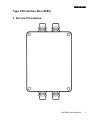
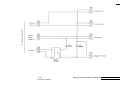
Type CR Interface Box (Z085)
1. Service Procedures
2. Technical Information
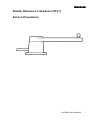
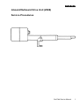
Rudder Reference Transducer (Z131)
Service Procedures
Fluxgate Compass Transducers (Z130)
Service Procedures
Fluxgate Compass Transducer (Z105)
Service Procedures
Rudder Reference Transducer (Z060)
Service Procedures
Masthead / Pushpit Windvane Transducers (Z080,
Z087)
Service Procedures
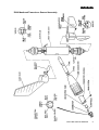
Linear Drive Units (Z029, Z032, Z039, Z058, Z059)
Service Procedures
Rotary Drive Units (Z028, Z031, Z037)
Service Procedures
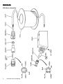
Hydraulic Drive Units (Z030, Z033, Z041, Z064,
Z065, Z066, Z067, Z081)
Service Procedures
I/O Sterndrive Drive Unit (Z088)
Service Procedures
SeaTalk Service Manual
3
Autohelm
ST7000 Basic System
1. Service Procedures
SeaTalk Service Manual
1
Autohelm
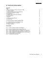
ST7000 System Index
1.
2.
3.
4.
5.
6.
7.
2
Introduction
System Description.
Operating/Calibration Instructions.
3.1 Operation
3.2 Operating Hints
3.3 Additional Information for Sailing Vessels
3.4 Calibration
3.5 Fluxgate Compass - Automatic Deviation Correction
Common System Problems.
Track Control Interfacing.
5.1 Inverted Data.
5.2 Conversion of Units.
5.3 Alarm Messages.
5.4 N.M.E.A. Input Format.
Special Functions.
6.1 Display of Software Version.
6.2 Permanent Watch Alarm Mode.
6.3 Display Test Mode. .
6.4 LCD Contrast Ratio Adjustment. .
Service Visit to a Vessel.
7.1 Onboard Diagnostics.
SeaTalk Service Manual
Page
3
3
4
4
8
10
12
15
16
17
17
17
17
18
19
19
19
19
19
20
21
Autohelm
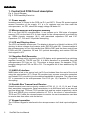
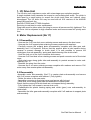
1. Introduction
The ST7000 system section of this manual contains full system operating instructions
and service procedures for the installed autopilot. Further indepth diagnostics are
available for each module in the relevant product sections.
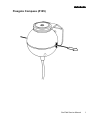
2. System Description
The ST7000 is a modular autopilot system that can be built up to match the individual
requirements of all vessels. A range of high efficiency Rotary, Linear,
Inboard/Outboard and Hydraulic drive units are available to match all types of
steering systems.
The ST7000 is SeaTalk compatible providing full data sharing with the Autohelm
range of SeaTalk Instruments.
Early systems (pre March 90) were supplied with Z060, Z105 Rudder Reference and
Fluxgate transducers. Later systems use the Z131 and Z130 transducers.
The ST7000 course computer can be used with all Seatalk compatible control units
and will operate all of the following drive units:
Z039
Z037
Z041
Z081
Z088
Z029
Z058
Z032
Z059
Z028
Z031
Z030
Z033
Z064
Z065
Z066
Z067
Linear Drive Type 1
Rotary Drive Type 1
Hydraulic Pump Type 1
Hydraulic Pump Type 0
I/O Sterndrive
Linear Drive Type 2 (1 2v)
Linear Drive Type 2 (12v) Short Stroke
Linear Drive Type 2 (24v)
Linear Drive Type 2 (24v) Short Stroke
Rotary Drive Type 2 (12v)
Rotary Drive Type 2 (24v)
Hydraulic Pump Type 2 (1 2v)
Hydraulic Pump Type 2 (24v)
Type CR 3L/min (1 2v) via Z085 Interface Box
Type CR 3L/min (24v) via Z085 Interface Box
Type CR 4.5L/min (12v) via Z085 Interface Box
Type CR 4.5L/min (24v) via Z085 Interface Box
SeaTalk Service Manual
3
Autohelm
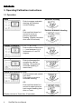
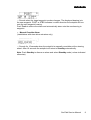
3. Operating/Calibration instructions
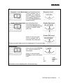
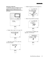
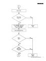
3.1 Operation
Automatic Heading
Auto
Push to engage automatic
steering and maintain
current heading.
OR
Push and hold down for 1
second to return to
previous automatic
heading. (Display returns to
Auto after 10 seconds).
Course Changes (—1, +1, —10, +10)
Previous Automatic Heading
New Automatic Heading
Push to alter course to port
(—) and starboard (+) in
increments of 1 and 10
degrees.
Current Heading
Standby
Push to disengage the
autopilot for manual
steering. (The previous
automatic heading is
memorised).
Track (see operating hints)
Push to select track control
from Auto.
Push again to return to
automatic steering.
OR
Push and hold down for 1
second to select previous
track control heading from
Auto or Track.
(Display returns to Track after 10 seconds).
4
SeaTalk Service Manual
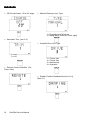
Automatic Heading
Autohelm
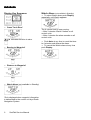
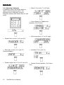
Response
•
Response Level Adjustment (see Operating Hints)
Push to increase ( ▲ ) or
decrease ( ▼ ) response
level. To display response
level without changing it
push both Response keys
together briefly.
Response Level
•
Rudder Gain Adjustment (see Operating Hints)
Push and hold down for 1
second both Response keys
together to display rudder
gain level.
Rudder Gain Level
Rudder Gain Level
Within 10 seconds push
once to increase ( ▲ ) or
decrease (▼) rudder gain.
(Response and Rudder levels are displayed for 10 seconds only)
Illumination Level
Illumination
Push and hold down Display
for 1 second to switch on
illumination.
Within 10 seconds push
Display to select illumination
level.
3
2
1
OFF
=High
=Medium
=Low
=Off
(Illumination level is displayed for 10 seconds only)
SeaTalk Service Manual
5
Autohelm
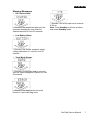
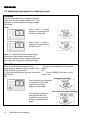
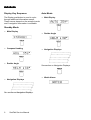
Display Key Sequence
•
• To select Watch alarm push Display
repeatedly until Watch appears.
Cross Track Error*
◄ or ► indicates direction to steer
•
Bearing to Waypoint*
•
Distance to Waypoint*
•
Watch Alarm (not available in Standby)
*Only displayed when waypoint information
is transmitted to the control unit by a Radio
Navigation System.
6
Watch Alarm (not available in Standby)
SeaTalk Service Manual
The 4 minute timer is now running:
—After 3 minutes ‘Watch’ flashes on all
control units.
—After 4 minutes the alarm sounds on all
control units.
• Push Auto at any time to reset the timer
to 4 minutes and silence the alarm.
• To cancel the Watch alarm at any time
push Display.
Autohelm
Warning Messages
•
Off Course Alarm
—Sounds if the vessel deviates from the
automatic heading by more than the
selected amount for over 20 seconds.
•
—Sounds if the cross track error exceeds
0.30n.m.
Note: Push Standby to silence an alarm
and select Standby mode.
Low Battery Alarm
—Sounds if the course computer supply
voltage falls below 11 volts for over 20
seconds.
•
Track Mode Alarms
—Sounds if no waypoint data is received
from the Radio Navigation System for over
20 seconds.
—Sounds if the data has the incorrect
format or if an invalid flag is set.
SeaTalk Service Manual
7
Autohelm
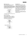
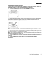
3.2 Operating Hints
Response Level Adjustment
The ST7000 has three response levels
which enable tighter course keeping to be
achieved in certain cases:Level 1— Automatic Sea State Control
Level 2— Automatic Sea State Inhibit
Level 3— Automatic Sea State Inhibit and
counter rudder.
When the autopilot is switched on, the
response level is set to 1. This provides the
best
compromise
between
power
consumption and course keeping accuracy
and is suitable for nearly all situations.
Increasing Response level provides tighter
course keeping at the expense of increased
power consumption and general wear and
tear. It is advisable to use the minimum
response level necessary to achieve the
desired course keeping accuracy. On larger
power vessels level 3 can improve slow
speed steering where the natural yaw
damping of the vessel is reduced.
Note: Level 3 is not recommended for use
at planing speeds or in rough seas.
+
Track
To make full use of Track control the
following simple points should be observed:• Always steer the vessel to within 0.1n.m.
of track and bring the heading to within 5° of
the bearing to the next waypoint before
selecting Track.
• Always check that there are no
navigational hazards either side of the
intended track.
• Always maintain an accurate log with
regular plots to verify the computed position
read from the Radio Navigation Receiver.
• Maintain a proper lookout at all times.
Automatic Trim
If Automatic Trim has been selected during
calibration the 5T7000 will correct for trim
changes. This correction can take up to
three minutes to apply the rudder offset
necessary to restore the set automatic
heading. Large course changes which
change the apparent wind direction can
produce large trim changes. In these cases
the autopilot will not immediately
8
SeaTalk Service Manual
assume the new automatic heading, and
only settle onto course when the Automatic
Trim has been fully established.
It is recommended the following procedure
is adopted for large course changes.
• Note required new heading.
• Select Standby and steer manually.
• Bring vessel onto new heading.
• Select Auto and let vessel settle onto
course.
• Bring to final course with 1° increments.
It is sound seamanship to make major
course changes only whilst steering
manually. In this way any obstructions or
other vessels may be cleared properly and
due account taken of the changed wind and
sea conditions on the new heading prior to
engaging the autopilot.
Rudder Gain Adjustment
The rudder gain level selected during initial
sea trials will normally provide excellent
steering performance over a wide range of
conditions. However, it may be noticed that
the autopilot tends to be a little less stable
on northerly headings in the higher latitudes
of the northern hemisphere (and conversely
southerly headings in the southern
hemisphere). This is caused by the
increasing angle of dip of the earth’s
magnetic field at higher latitudes, which has
the effect of amplifying rudder response on
northerly headings. The tendency towards
northerly heading instability is usually more
obvious in higher speed craft and when it
occurs can be corrected by reducing the
rudder control setting. At speeds in excess
of 30 knots, a reduction of two levels can
often be required on headings between
315° and 045° (northern hemisphere) or
135° and 230° (southern hemisphere).
CAUTION
On planing vessels improved course
keeping at displacement speeds can
sometimes be achieved by increasing the
rudder gain level. If this is done, it must be
decreased again before opening the throttle
as oversteer can be extremely violent at
planing speeds.
Autohelm
Unsatisfactory Steering Performance
If the 5T7000 has been installed and set up
in accordance with the instructions in the
Installation Manual it will provide excellent
steering performance over a wide range of
conditions.
If performance drops but the autopilot is still
working correctly, the following simple
checks should find the fault:• Has a magnetic influence been
introduced near the fluxgate compass? i.e.
anchor,
chain,
radio
equipment,
loudspeaker, tools, generator etc. Check
that the autopilot compass heading still
corresponds with the steering compass.
• Are all fuses intact, circuit breakers
engaged?
• Are all screw connections tight and free
of corrosion.
• If the autopilot fails to hold course check
the Rudder Gain level. Has it been changed
from the initial sea trials level (check in
Installation Manual)?
• If the vessel wanders check that the
Rudder Reference Transducer linkage is
secure with no free play.
Hydraulic Drive Units only:• Check that all unions are tight and bleed
system to remove air.
Failure to Disengage
The mechanical drive actuators of the
ST7000 are designed to ‘Fail Safe’ — When
power is disconnected the drive unit will
disengage leaving the steering system free
for manual control.
When Standby is selected the actuator will
Disengage leaving the steering free.
It is remotely possible that a fault could
develop which could cause the actuator to
remain engaged even when Standby is
selected. If this happens:• DISCONNECT THE MAIN CIRCUIT
BREAKER TO THE AUTOPILOT — THE
STEERING WILL IMMEDIATELY BE FREE.
or
• IN AN EMERGENCY THE ACTUATOR
CLUTCH
CAN
NORMALLY
BE
OVERRIDDEN
BY
TURNING
THE
STEERING WHEEL HARD.
It is emphasised that this fault is extremely
unlikely and can be immediately corrected
as described.
If preferred a separate Override switch can
be fitted close to the steering position which
will break the actuator clutch drive for
Emergency Use.
Safety
Passage making under autopilot is a
very pleasant experience which can lead
to the temptation of relaxing permanent
watch. This must always be avoided no
matter how clear the sea may appear to
be.
It is the responsibility of the skipper to
ensure the safety of his vessel at all
times by careful navigation and that all
crew members are familiar with the
procedures required to engage and
disengage the autopilot.
When searoom is restricted, a crew
member must be close to a control unit
at all times if under Autopilot control.
On Power craft permanent watch should
be maintained at the steering station
when at speed with the Autopilot
engaged.
SeaTalk Service Manual
9
Autohelm
3.3 Additional Information for Sailing Vessels
Autotack
The ST7000 has a built in Autotack function
which will turn the vessel through 100°. This
operates in both compass and vane modes
as follows:Vane
Push +1 and -1 -10 keys
together to initiate a tack
turning to Starboard.
Push -1 and —10 keys
together to initiate a tack
turning to Port.
Note: It is important that the rudder angle
transducer is accurately aligned as the
Autotack function mirrors standing helm and
any offset will change the initial tack angle.
Wind Trim
Wind Trim allows the autopilot to be
supervised by apparent wind direction. The
wind direction is read either:—From the SeaTalk bus (requires Autohelm
ST50 wind).
OR
—Directly from a Masthead Transducer
(Z080).
OR
— From an NMEA 0183 input on the
control unit.
Automatic Heading
Push both red keys together
to select Wind Trim and
maintain the current
apparent wind angle.
Previous Automatic Heading
Push and hold down for 1
second both red keys
together to return to the
previous apparent wind
angle.
10
SeaTalk Service Manual
Autohelm
Wind Change Alarm
Wind Trim uses the fluxgate compass as
the primary heading reference and
automatically adjusts the compass heading
to maintain the original apparent wind angle.
If changes in apparent wind angle adjust the
original automatic heading by more than 15°
the wind change alarm will sound.
Using Wind Trim
It is important to understand that “Wind
Trim” prevents over-reaction to gusts or
sudden wind shifts. One minute is required
to change the heading in response to a
permanent change in apparent wind angle.
Do not attempt to override the automatic
sequence with the course change buttons.
In gusty conditions sail a few degrees off
the wind and pay frequent attention to sail
trim and helm balance using the rudder
angle indication.
Performance will normally be improved by
reefing headsail and mainsail a little early
rather than too late.
—The alarm is silenced by pushing both red
keys together briefly.
Display of Wind Angle
If the wind angle information is supplied
using the NMEA 0183 input or SeaTalk bus,
the apparent wind angle and tack sense (P
& S) is added to the display menu and
accessed via the Display button.
•
Apparent Wind Angle
SeaTalk Service Manual
11
Autohelm
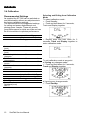
3.4 Calibration
Recommended Settings
As supplied the ST7000 can be switched on
and tested safely without any adjustments to
the factory calibration settings.
The table below lists the suggested settings
for sailing and power displacement and
planing power vessels. These will provide
good performance for initial sea trials and can
be fine tuned later to optimise performance.
Vessel Type
Displacement
Planing
Factory preset
Set to
Rudder Gain
(level)
Rate Gain
(level)
Rudder Angle Limit
(degrees)
Turn Rate Limit
(degrees/sec)
Cruise Speed
(knots)
Off Course Alarm
(degrees)
Trim Level
Drive Type
Rudder Position
Deadband (level)
See 3.7
12
5
2
2
1
30
30
20
5
8
25
20
20
1
1
Autopilot Drive Unit Type
Mechanical
Hydraulic
Factory preset Set to
3
4
1
1
SeaTalk Service Manual
Selecting and Exiting from Calibration
Mode
To select calibration mode:• Push Standby.
• Push and hold down for 2 seconds,
Track and Display together.
• Repeat push and hold down for 2
seconds, Track and Display together to
enter calibration mode.
To exit calibration mode at any point.
a) Saving any changes made:• Push and hold down for 2 seconds,
Track and Display together.
b) Ignoring any changes made:
• Push Standby.
Autohelm
Adjusting Calibration
In calibration mode, the display button is
used to scroll through the menu. The
displayed value is adjusted using the
Response buttons (hold button down for
fast scroll).
•
•
Rudder Angle Limit, 15 to 40 (see 3.6).
•
Rate of Turn Limit, 2 to 20°/sec.
Rudder Gain, levels 1 to 9, (see 5.5)
• Cruise Speed, for Track mode
operation, 4 to 60 knots.
• Rate Gain, levels 1 to 9, (see 5.6)
(Counter Rudder).
SeaTalk Service Manual
13
Autohelm
•
Off-Course Alarm, 15 to 40° angle.
•
Manual Steering Lever Type.
1 = Proportional (Follow up)
2 = Bang Bang (Drive left, Drive right)
•
Automatic Trim, (see 5.4).
•
Autopilot Drive Unit Type.
1 = on
0 = off
1 = Future Use
2 = Future Use
3 = Mechanical
4 = Hydraulic
• Remote Control Identifier. (For
Future Use).
• Rudder Position Deadband (levels 1 to 9),
(See 3.7).
14
SeaTalk Service Manual
Autohelm
3. 5 Automatic Deviation Correction
The ST7000 will correct the fluxgate compass for any deviating magnetic fields. This
should be carried out in calm conditions preferably in flat water.
• To select compass adjust Push and hold Standby for 1 second.
• Keeping boat speed below 2 knots, turn the vessel slowly so that it takes at least
3 minutes to complete 360°. Keep turning until the display changes to show the
amount of deviation the autopilot has corrected:-
Note: lf the amount exceeds 15°, it is recommended the fluxgate should be re-sited.
• Use the course change buttons to adjust the displayed heading until it agrees with
the steering compass or a known transit bearing.
Note: 000° is always followed by OFF. This will suppress the display of compass and
automatic headings on the control unit.
• To exit compass adjust and store the compass settings push and hold Standby for
1 second.
• To exit compass adjust without saving any new settings push Standby
momentarily.
SeaTalk Service Manual
15
Autohelm
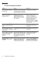
4. Common System Problems
Problem
System displays ‘Manual’
mode instead of ‘Standby’
on power up.
Cause.
Solution.
Early systems had poor colour Reverse Blue and Green
definition on terminal boards. connections on Fluxgate.
Blue and Green connections
to the Fluxgate are reversed.
System will not pick up
N.M.E.A. data from a
suitable receiver.
Early systems with
software issues prior to
66E (Z083/084) and 66C
(Z082) were not fitted with
Nav software.
Replace software in both
Course Computer and
Control unit with latest
versions if pre 66E or 65C
(Both software issues can
easily be checked by
pressing +10 and -10 degree
course change keys together
for 2 seconds.
System displays ST 7000
for 2 sec’s followed by ‘NO
LINK’.
Seatalk Bus non operational.
Cabling error between
control units and Course
Computer.
System displays ‘GYRO’
Wind Anemometer connected Remove yellow connection
mode instead of ‘STANDBY' to pilot.
from AUX 1.
on power up.
System displays maximum
rudder angle on power up
regardless of rudder
position.
Early systems had poor colour Reverse Blue and Green
definition on terminal boards. connections on rudder
Blue and green connections
reference.
to the rudder reference are
reversed.
System displays ‘ST7000’ or Inrush currents on the power
‘STANDBY’ when Auto is
amplifier reset either the
engaged.
Control unit or the Course
Computer Microprocessor.
16
SeaTalk Service Manual
Add C6 (100uF capacitor) to
the power amplifier PCB.
Systems from S/N 890040 on
have this mod incorporated.
Autohelm
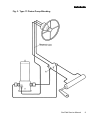
5. Track Control interfacing.
In most cases interfacing the ST7000 to either a GPS, Decca, Loran or Satellite
Navigation system is a simple and straight forward task, so long as the requirements
set out in section 6 of the installation manual are met. There are however a few
exceptions:
5.1 Inverted Data.
Some receivers, notably some of the Furuno range and early Navstar models,
transmit data in an inverted format with respect to 5V. This is easily seen as the data
line will idle high with respect to 0V in between data transmissions. In these cases
the NMEA cable on the rear of the control unit must be wired with the red wire
connected to 5V, (this is normally available on the receiver terminal block), and the
blue wire connected to the data line.
5.2 Conversion of Units.
The Control Unit will convert all units of distance to Nautical Miles. Therefore, any
receivers displaying Cross Track Error or Distance To Waypoint in either Kilometres
of Statute miles etc will have their data displayed on the Control Unit in Nautical
Miles.
5.3 Alarm Messages.
Track mode has 3 alarm messages:1.
2.
No Data
Data Error
3.
Large XTE
If a standard N.M.E.A sentence is not received by the ST7000.
The ST7000 has recognised the incoming data as N.M.E.A but
has detected an invalid flag. This is normally due to poor signal
strength at the receiver.
Cross Track Error greater than O.3NM.
Errors 1 and 2 can provide valuable information as to where an installation problem
might lie. The ‘NO DATA’ message indicates the ST7000 is not receiving N.M.E.A
data due to either the receiver output not being enabled or more likely a wiring error
between the receiver and the pilot. The ‘DATA ERROR’ message indicates the
ST7000 is receiving data recognised as N.M.E.A but has an invalid flag set. This is
normally due to the receiver having a low signal strength or a high noise figure.
SeaTalk Service Manual
17
Autohelm
5.4 Autohelm 7000 N.M.E.A 0183 Data input Format.
The 7000 must receive Cross Track Error data at least once every 30 seconds.
If a display of Waypoint bearing and distance is required then this information must
be received at least once every 30 seconds. All N.M.E.A data is read into a buffer
thus enabling the 7000 to cope with delays between characters and delays between
sentences. All Talker Identifier characters, i.e. RA, DE, LC etc. are ignored allowing
interface with any type of equipment so long as the sentence type is one of the
following:Track
Control
XTE
XTR
APA
APB
RMB
Bearing to
Waypoint
APB
BPI
BWR
BWC
BER
BEC
RMB
Distance to
Waypoint
WDR
WDC
BPI
BWR
BWC
BER
BEC
RMB
Apparent Wind Speed &
Direction
VWR
Apparent Wind Speed and Angle can be received from any external equipment
transmitting the N.M.E.A. VWR header. The ST7000 will only display apparent wind
direction but will convert and retransmit both apparent wind speed and apparent wind
direction on the Seatalk bus. This information can then be displayed on an ST50 wind
instrument acting as a repeater.
18
SeaTalk Service Manual
Autohelm
6. Special functions.
6.1 Display of Software Version
It is possible to display the version number of both Course Computer and Control
Unit software installed in a particular system. This is achieved by pressing both the
+10 and -10 keys together for 2 seconds and releasing. The display will show the
Control Unit Version (65 followed by Issue Level) for 10 seconds, followed by Course
Computer Version (66 followed by Issue Level). The pilot must be in standby mode at
the time. Each version is displayed for 10 seconds before the pilot reverts to standby.
A software history for each product is shown in the relevant Service Section.
6.2 Permanent Watch Alarm Mode.
The ST7000 autopilot can be set up in a permanent watch alarm mode, as required
by the Sea Fish Industry Authority (S.F.l.A).
It must be stressed that the selection of this mode is permanent and can only be
reversed by returning the Course Computer to Nautech.
Permanent Watch Alarm is achieved by first entering the calibration menu. Once in
calibration, regardless of display message, press the Auto, Standby, and Track keys
together for 1 second before releasing. The display will now show ‘SELECT WATCH’.
The user now has 10 seconds to select permanent watch alarm mode by again
pressing Auto, Standby and Track together for 1 second. The display will then show
‘WATCH ON’ for 10 seconds before reverting back to ‘CAL’. A normal exit from
calibration mode must now be executed.
6.3 Display Test Mode.
All display segments on the control unit can be switched on by pressing the +10, -10,
Standby and Display keys together. This mode can only be accessed after the unit
has been powered up with the yellow SeaTalk data wire open circuit. (This is best
disconnected in the Course Computer Connector box (Bus 1 and Bus 2).)
6.4 LCD Contrast Ratio Adjustment.
In certain circumstances, it may be necessary to adjust the contrast ratio of the Z082
Control Unit LCD. This procedure is detailed in Section 4 of the ZO82 Control Unit
Section.
SeaTalk Service Manual
19
Autohelm
7. Service visit to a vessel.
When a service visit to a vessel is made the most common fault en-countered is likely
to be poor connections or inadequate power supplies. These should be thoroughly
checked before the Service visit diagnostic procedure is carried out.
When trying to locate a fault it should be remembered that most failures will occur in
the Course Computer with the Control Units as the next most likely.
It should be noted that the calibration variables and auto deviation correction will
require re-setting if the Course Computer, Course Computer Software or its PCB are
exchanged. A procedure for carrying out this operation is given in section 3. Always
note the Course Computer calibration settings before removing from the vessel.
20
SeaTalk Service Manual
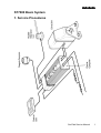
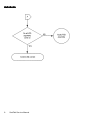
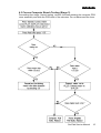
Autohelm
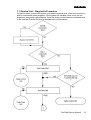
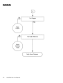
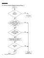
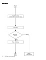
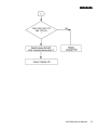
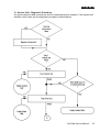
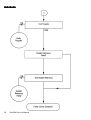
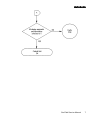
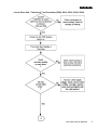
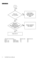
7.1 Service Visit - Diagnostic Procedure
On arrival check for bad connections (corroded connector pins, loose connectors etc)
and for inadequate power supplies. If the system still exhibits a fault, then use the
diagnostic procedure outlined below. Once the faulty module has been detected refer
to the relevant Product Section for detailed service information.
SeaTalk Service Manual
21
Autohelm
22
SeaTalk Service Manual
Autohelm
Z082 Control Unit
1. Service Procedures
SeaTalk Service Manual
1
Autohelm
Contents
2
1. Description
2. Dismantling
3. Re-assembly
4. Display Contrast Adjustment
5. Functional Test
6. Product History
7. Software History
8. Spares Numbers
Page
3
3
3
4
7
9
9
9
Illustrations
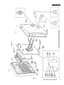
Fig. 1. Z082 Control Unit General Assembly
Fig. 2. LCD/Diffuser Assembly
5
6
SeaTalk Service Manual
Autohelm
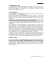
1. Description
The Z082 Control Unit is SeaTalk compatible and consists of a single PCB built using
surface mount technology. It can be used with both 12V and 24V SeaTalk Course
Computers. The unit can also be functionally tested without the use of special
equipment using the procedure outlined in figure 3.
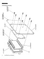
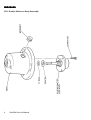
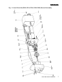
2. Dismantling (ref fig 1.)
Note: To prevent damage to the printed face of the unit all work should be carried out
on a flat surface covered in foam rubber. A conductive surface will prove beneficial in
helping to prevent dust accumulation caused by static on the workbench.
1. Unscrew and remove the 6 case securing screws from the rear cover. Push each
cable loom assembly back through its grommet so as to obtain working clearance to
the PCB (fig 1).
Note: Failure to push the cables back to ease removal may damage the cable to PCB
assembly. If cables are very tight in grommets apply a small smear of silicon grease
to outer sheath, (grease can be wiped off after reassembly).
If removing the PCB assembly, it will be necessary to de-solder the cables from the
PCB. Great care should be exercised when de-soldering so as not to damage the
pads on the PCB.
2. Unscrew and remove the 10 screws which secure the PCB to the facia.
Note: Do not at this stage remove the screws which secure the LCD assembly to the
PCB. (fig 2.).
3. Before removing the LCD ensure that lint free and preferably anti static finger cots
are worn to prevent the LCD or elastomers getting dirty or greasy.
4. Unscrew and remove the 8 LCD housing retaining screws, (fig 2.). Be careful to
hold the LCD surround, LCD, and diffuser when dismantling. Lift away from the PCB
and store carefully.
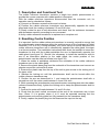
3. Reassembly
Reassembly is a straight reversal of the above procedure but note the following
points:
1. Note the correct orientation of the various looms and core colours to the PCB pads
(fig 1).
2. Ensure the LCD is correctly orientated relative to the PCB (fig 2).
3. Ensure the diffuser is correctly orientated relative to the LCD and PCB (fig 2).
4. Always ensure the board is tightened down sequentially to ensure the load is
evenly spread.
SeaTalk Service Manual
3
Autohelm
5. When finally refitting the cover to the facia ensure that the cover is in the correct
position relative to the cables and pull the cables back through the grommets as the
cover is lowered onto the facia. Wipe off any excess grease from the cable sheaths.
6. Use only hand screwdrivers for reassembly to ensure screws are not over
tightened and elastomers are compressed uniformly. Rotate screws anticlockwise to
locate in the thread before tightening.
7. Re-check for full function after reassembly to check the LCD has not been
damaged or looms incorrectly soldered.
4. Display Contrast Adjustment
The Display Contrast on the Z082 Control Unit can be manually adjusted to suit
installations where the LCD is normally viewed from significantly above or below, or
when a replacement LCD with different drive characteristics has been fitted.
1. Remove power from the unit.
2. Unscrew the mounting thumb nuts and ease the Control unit forward from its
mounting position.
3. Unscrew and remove the 6 case screws from the rear cover. Push each cable
loom back through its grommet so as to obtain working clearance to the PCB (fig 1).
Note: If cables are tight in grommets then apply a small smear of grease to the outer
sheath, (grease can be wiped off after reassembly).
4. Re-connect power.
5. View Control unit from normal operating angle.
6. Adjust vrl, (see figure 1 for location) to obtain optimum display legibility.
7. Refit the cover to the facia ensuring correct positioning relative to the cables. Pull
the cables back through the grommets as the cover approaches the facia.
8. Secure Control unit in its original position.
Note: Use only hand screw drivers to reassemble to ensure screws are not over
tightened.
4
SeaTalk Service Manual
Autohelm
Control Unit General Assembly (Z082)
Fig. 1.
SeaTalk Service Manual
5
Autohelm
LCD Display Assembly
Fig. 2.
6
SeaTalk Service Manual
Autohelm
5. Functional Test
SeaTalk Service Manual
7
Autohelm
8
SeaTalk Service Manual
Autohelm
6. Product History (Z082)
Change
Production Start
Serial Number
290001
Track Compatibility
690075
White Back Light diffuser
introduction
Protective Cover supplied
with unit
SeaTalk Cable supplied
with unit
Comments
When used with a Track Compatible Course Computer
890007
100001
300056
7. Software History (Z082)
Version
B
C
Change
Initial release
(S/No. 290001)
Track function added, Rudder Angle
display updates at a faster rate.
(S/No. 690075)
Course Computer Compatibility
All versions
All versions but must be used with a
track compatible Course Computer if
the track function is required.
8. Spares Numbers - Control Unit (Z082)
Item
Catalogue No
Double Skin mounting kit
Q003
PCB Assembly
LCD
White Backlight Diffuser
Protective Cover
Q004
Q026
Q023
D122
Comments
Allows Control Unit to be mounted
on up to 4" thick bulkheads
No LCD included
SeaTalk Service Manual
9
Autohelm
10
SeaTalk Service Manual
Autohelm
2. Technical Information
Contents
1.
1.1
1.2
1.3
1.4
1.5
1.6
1.7
1.8
1.9
Circuit description
Power Supply
Microprocessor and Program Memory
LCD and Display Driver
Negative Rail Generator
N.M.E.A. Interface
Seatalk Bus Transmit and Receive
Keypad Operation
Buzzer Operation
Illumination Drive
Illustrations
Fig.1. Circuit Diagram
Fig.2. PCB Assembly/Parts List
Page
2
2
2
2
2
2
2
3
3
3
5
7
SeaTalk Service Manual
1
Autohelm
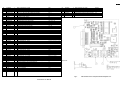
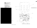
1. Control Unit PCB Circuit Description
Circuit Diagram Fig. 1.
PCB Assembly/Parts List Fig. 2.
1.1 Power Supply
Incoming power is routed to the PCB via PL1 and SKT1. D4 and D20 protect against
reverse connection of the supply. IC1 is a 5V regulator and can also reset the
microprocessor, via TR1, should the supply voltage fall below approximately 6V.
1.2. Microprocessor and Program Memory
lC6 is an Intel 80C32 microprocessor. It can access up to 32k bytes of program
memory (lC5) via the latch lC4. A clock signal for the microprocessor is provided by
an 1 1MHz ceramic resonator (XL1), and associated capacitors C7 and C8.
Capacitors C6, C9 and C10 provide decoupling.
1.3. LCD and Display Driver
The LCD is a Nautech custom part. The display is driven by a Hitachi LCD driver
(IC3) deriving its drive voltages from resistor chain R24-R27 and VR1.
Communication to the microprocessor is via a 4 bit parallel bus (DB4 to DB7) and the
three control lines E, R/W and RS. Capacitors C18 and C22 provide decoupling and
resistor R44 the clock signal for lC3.
1.4. Negative Rail Generator
A negative voltage rail is required by the LCD display and is generated by a switching
regulator formed by TR11, D10 and D21. A 4.8KHz waveform is generated from the
microprocessor P3.4 (pin no. 16). This drives a charge pump, via transistorTR11,
pumping charge from C19 via D1O and C20. The negative rail is then stabilised by
D21 and R60.
1.5. N.M.E.A Interface
NMEA data is fed to the control unit via PL2 and isolated from the rest of the circuit
using the opto-isolator (lC7). Diode D1 provides input reverse connection protection
and resistor R35 is tuned to give the desired bandwidth of operation. The output from
IC7 is connected to the microprocessor Port P3.2 (pin 14). Capacitor C21 provides
decoupling.
1.6. SeaTalk Bus Transmit and Receive
SeaTalk transmit and receive circuitry consists of TR5, 6, 7, 8, 9, 14 and 15 and their
associated components. Data transmission is at 4800 band with a low start bit and
line idling high. TR7 and TR8 provide high and low drive respectively, whilst TR14
and R57 give overload protection to TR8 in the event of misconnection. TR5 and TR6
allow the microprocessor to monitor its own transmissions and also to receive data
from other units on the bus.
2
SeaTalk Service Manual
Autohelm
1.7. Keypad Operation
The 10 button key pad is configured in a 4*3 matrix and connected to the
microprocessor P1.0 and P1.6 (pins 2 to 8). Each key is diode isolated to enable
multiple key presses to be decoded.
1.8. Buzzer Operation
TR2 and TR3 are configured as an astable multivibrator with a nominal frequency of
2.7KHz. TR4 is used to switch the buzzer with TR13 acting as an invertor to turn the
buzzer off during a micro-processor reset.
1.9. Illumination Drive
TR10, 12 and 16 provide a constant current drive for lamps LP1, LP2, LP3 and LP4.
The current is set by resistors R56 and R62. TR12 is an inverting buffer to turn off the
lights during a microprocessor reset. Illumination levels are given by pulse width
modulation of drive line P3.3 (pin 15 of lC6).
SeaTalk Service Manual
3
Autohelm
4
SeaTalk Service Manual
Autohelm
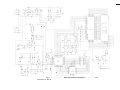
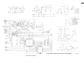
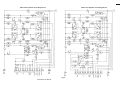
Fig. 1.
SeaTalk Service Manual
Z082 Control Unit Circuit Diagram
ISS C
5
Autohelm
6
SeaTalk Service Manual
Autohelm
NOTES
1. ALL SURFACE MOUNT CAPACITORS AND RESISTORS TO HAVE NICKEL BARRIER
SOLDER PLATED TERMINATIONS
2. ITEM 4 (15036) TO BE SANDWICHED BETWEEN ITEM 5 (15039) AND PCB TO
INSULATE HEATSINK FROM 5V TRACK CONNECTED TO IC 1 (PIN 2)
3. ITEM 6 15085) TO LIE FLAT ON P.C.B. AS SHOWN.
47
46
OR
EITHER
1
1
45
OR
1
44
EITHER
1
LCD DISPLAY DRIVER KS0062 (SAMSUNG)
LCD DISPLAY DRIVER HD44780 (HITACHI)
AND
TRANSISTOR BC337 NPN (TO BE ASSEMBLED WITH
MAXIMUM LEAD LENGTH =4MM)
TRANSISTOR SOT89 BCX68 NPN
IC3
TR16
43
42
41
10
1
1
40
39
38
3?
1
1
1
1
PLUS
CONTACT CLICKER 00K-73470 S1, S2, S3, S4, S5, S6, S7, S8, S9, S10
CHIP TRIMMER RESISTOR 1K MURATA RVG 4F03A-102VM
OPTO ISOLATOR 6N139 LEADS TO BE FORMED FOR
BUTT JOINT CONNECTION (ie HPs OPTION 100)
MICRO ROM LESS 80C32 12MHz PLCC
HCMOS LATCH 74HC373
VOLTAGE REGULATOR LM2925
TRANSISTOR SOT 23 BC807 PNP
36
14
TRANSISTOR SOT 23 BC817 NPN
35
34
33
32
31
30
29
28
27
26
25
24
23
22
21
20
19
18
17
16
15
14
13
12
11
10
9
8
7
6
5
4
3
2
1
26006
15085
15039
15036
07164
3015-028
3010-036
5
3
1
3
2
1
2
3
1
1
1
4
1
1
1
1
1
3
1
1
9
4
3
3
2
1
1
1
1
1
1
1
1
1
10
DIODE SOT 23 BAW56
D6, D7, D8, D15, D16
DIODE SOT 23 BAV99
D2, D10, D21
DIODE SOT 23 BAS 16
D12
DIODE SOT23 BAS19
D1, D4, D20
CAPACITOR SOLID TANT. 10UF ±20% 6V3(SIZE C)
C19, C20
1206 CAPACITOR 1000pF ± 10% 5OV X7R
C11
1206 CAPACITOR 33pF ±5% 50V COG
C7, C8
1206 CAPACITOR 22pF ±5% 50V X7R
C2, C4, C5
1206 CAPACITOR 0.1µF ±20% 50V X7R
ELECTROLYTIC CAPACITOR 100uF ±20% 6.3V MIN 5.5 MAX C3
1206 RESISTOR 100K 5% 0. 125W
R35
1206 RESISTOR 1K0 2% 0.125W
R24.R25R26R27
1206 RESISTOR 220R 5% 0. 125W
R42
1206 RESISTOR 680R 5% 0 125W
R60
1206 RESISTOR 10R0 1% 0.125W
R56
1206 RESISTOR 91K 2% 0. 125W
R44
1206 RESISTOR 8R2 5% 0.125W
R34, R47, R57, R59
1206 RESISTOR 39K 5% 0.125W
R10, R11, R19
1206 RESISTOR 22K 5% 0. 125W
R21
1206 RESISTOR 15K 5% 0. 125W
R12
R1, R2, R6, R7, R9, RZ2, R23, R50, R55
1206 RESISTOR 12K 5% 0. 125W
1206 RESISTOR 4K? 5% 0.125W
R13R32R54R58
1206 RESISTOR 2K2 5% 0.125W
R3, R14, R20
1206 RESISTOR 1K2 5% 0.125W
R31, R51, R52
1206 RESISTOR 470R 5% 0 . 125W
R5, R8
1206 RESISTOR 390R 5% 0. 125W
R18
1206 RESISTOR 13R0 1% 0.125W
R62
BUZZER KBS-27DB~3T
RIVSCREW 1712-3507 (AVDEL)
CERAMIC RESONATOR 11MHz (CSA 11.0MT)
XL1
HEATSINK REDPOINT TV58
TRANSISTOR MOUNTING PAD
28 PIN IC SOCKET
7000 CONTROL UNIT PCB DETAIL
CLICKER SEAL
DRG/PART N*
QTY
ITEMS
VR1
IC7
IC6
IC4
IC1
TR7
TR1, TR2, TR3, TR4, TR5, TR6, TR8, TR9,
TR10, TR11, TR12, TR13, TR14, TR15
DESCRIPTION
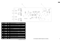
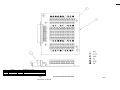
Fig. 2
SeaTalk Service Manual
.
Z082 Control Unit PCB Assembly/Parts List
ISS S
7
Autohelm
8
SeaTalk Service Manual
Autohelm
Z084 Course Computer (24V) & Z083 Course Computer
(12V)
Z084 COURSE COMPUTER (24V)
Z083 COURSE COMPUTER (12V)
1. Service Procedures
SeaTalk Service Manual
1
Autohelm
Contents
1. Description
2. Dismantling
3. Re-assembly
4. Functional Test
4.1 Bench Test (stage 1)
4.2 Bench Test (stage 2)
4.3 Bench Test (stage 3)
5. Product History
6. Software History
7. Spares Numbers
Page
3
3
4
7
8
14
15
16
16
16
Illustrations
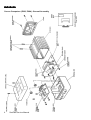
Fig. 1. Course Computer General Assembly
Fig. 2. Power Amplifier General Assembly
5
6
2
SeaTalk Service Manual
Autohelm
1. Description
The ST7000 course computer is SeaTalk compatible and consists of 2 PCB's, a
course computer and power amplifier. The course computer, which is built using
surface mount technology, contains a microprocessor and various analogue interface
circuitry. The power amplifier provides the motor drive, protection relays and 24V to
12V regulator (24V systems). This PCB is identical to that used on the Autohelm
6000 type 2 pilots (Z051 and Z052) and uses conventional through hole components.
The two PCB's are connected together via a 16 way ribbon cable. The same
computer PCB is used on both 12V and 24V systems. The power amplifier PCB is
built to two standards, one for 12V systems, and a second, which includes a 24V to
12V regulator, for 24V systems. A single design of terminal board is used for all drive
applications. This PCB has no active components and should be visually checked if
suspected faulty. Note:
If the course computer or its PCB are replaced, calibration values previously altered
from the factory settings will require re-setting. Also the Fluxgate Compass will
require re-linearising (auto deviation correction). Both of these procedures are
outlined in the 7000 system section.
2. Dismantling (reference figures 1 & 2)
1. Unscrew and remove 2 countersunk screws securing lid on terminal box section
and lift off.
2. Unscrew and remove 2 thumb nuts securing extrusion assembly to terminal box
unit and pull extrusion assembly away from terminal box.
3. Course Computer PCB
If servicing course computer PCB, unscrew and remove 4 pan head screws securing
the connector cover moulding to the extrusion and slide out cover and PCB
assembly. Disconnect power amp PCB loom and lift away the PCB assembly. If
necessary, remove the PCB from the moulded cover by unscrewing the 2
countersunk screws and nuts which fix the 'D' connector flange to the moulding.
4. Power Amplifier PCB
Repeat steps 1 to 3 but do not remove the computer PCB from the cover. Disconnect
the 16 way loom from the computer PCB and remove the plastic covers from the
power transistors. Unscrew all pan head screws and retain the shakeproof washers
where fitted. Lift out all transistors. Slide PCB out of extrusion from the open end.
Retain the insulators and caps fitted to the securing lugs on the PCB.
5. If servicing the terminal PCB, repeat steps 1 and 2. Remove the terminal PCB from
the terminal box by removing the 2 nuts securing the 'D' connector to the terminal
box, and the 2 securing screws at the front of the PCB, and remove the PCB
assembly.
SeaTalk Service Manual
3
Autohelm
3. Re-assembly
In all cases re-assembly is a reversal of the dismantling procedures above, but note;1. Ensure correct orientation of power amp PCB loom when reconnecting to the
computer PCB. Ensure a loom clip is fitted to the ribbon cable connector.
2. Ensure that insulating caps are all in place before sliding the power amp PCB back
into the extrusion. Ensure that the silpads are fitted between the transistors and the
extrusion.
3. Ensure that the correct transistor type is placed at each location. (Fig. 2).
4. Ensure that transistor/PCB securing screws are not loose, but do not over tighten.
4
SeaTalk Service Manual
Autohelm
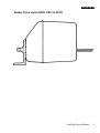
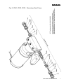
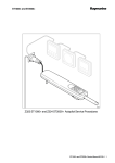
ST7000 Course Computer General Assembly Z083-12V and Z084-24V
Fig. 1.
SeaTalk Service Manual
5
Autohelm
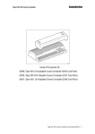
ST7000 Course Computer (Z083, Z084) - Power Amp PCB Assembly
Fig. 2.
6
SeaTalk Service Manual
Autohelm
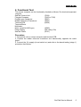
4. Functional Test
The Course Computer can be functionally checked by using the following procedure.
Pre checked equipment required;SeaTalk Control Unit (Z082)
Fluxgate Compass (Z105)
Pushpit Vane Transducer (Z087)
Rudder Reference Transducer (Z060)
Terminal PCB (Q006)
Terminal Block
Multimeter
Motor for Z083 (12V) (N002)
Motor for Z084 (24V) (N003)
Power Supply (min rating 20A)
SeaTalk Cable (D131)
Procedure:
a) Connect all units to course computer and terminal board PCB.
b) Position the rudder reference transducer arm diametrically opposite the cable
gland.
c) Connect 12V (Z083), 24V (Z084) electronic and heavy duty supplies (do not switch
on).
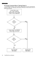
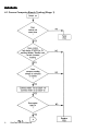
d) Start at Bench Test Stage 1. The procedure will determine if the course computer
is faulty or correct and in most cases will also identify the nature of the fault and
corrective action required. Some faults require further investigation and this is
covered in stage 2 and stage 3.
SeaTalk Service Manual
7
Autohelm
4.1 Course Computer Bench Testing (Stage 1)
8
SeaTalk Service Manual
Autohelm
SeaTalk Service Manual
9
Autohelm
10
SeaTalk Service Manual
Autohelm
SeaTalk Service Manual
11
Autohelm
12
SeaTalk Service Manual
Autohelm
SeaTalk Service Manual
13
Autohelm
4.2 Course Computer Bench Testing (Stage 2)
1. Proceeding from stage 1 bench testing, remove the four screws retaining the
computer PCB cover assembly and slide the PCB clear of the extrusion. Do not
disconnect the loom.
14
SeaTalk Service Manual
Autohelm
4.3 Course Computer Bench Testing (Stage 3)
Proceeding from stage 1 bench testing, remove 4 screws retaining the computer PCB
cover assembly and slide the PCB clear of the extrusion. Do not disconnect the loom.
SeaTalk Service Manual
15
Autohelm
5. Product History Course Computer (Z083 & Z084)
Change
Serial Number
Production Start
Track Function Introduced
290001
590206
Capacitor 'C6' (100µf) fitted to
power amplifier board
890040
Comments
Must be used in conjunction with a
Control Unit capable of supporting the
Track function
Cures occasional system reset to
Standby mode when initially engaging
Auto after power up.
6. Software History (Z083 & Z084)
Version Change
Control Unit Compatibility
S/No
C
Initial release
All versions
290001
D
Auto Seastate
problem cured
All versions
490081
E
Track function added All versions. If Track keeping algorithm is 590206
required then control unit must also be
Track Compatible
G
Trim function
Improved
All versions
500256
7. Spares Numbers - Course Computers (Z083 & Z084)
Item
Catalogue No.
Connector Unit terminal PCB
assembly
Q006
Course Computer PCB
assembly
Q007
Comments
Power Amplifier PCB assembly
(Z083)
M062
12v version
Power Amplifier PCB assembly
(Z084)
M063
24v version
PNP Power Transistors
(2offMJ11029)
L010
NPN Power Transistors
(2offMJ11028)
L009
16
SeaTalk Service Manual
Autohelm
2. Technical Information
Contents
Page
1. Circuit Description (Course Computer PCB)
1.1 Power Supplies
1 .2 Microprocessor and Program Memory
1.3 Analogue to Digital Converter
1.4 Clutch Drive
1.5 SeaTalk Bus Transmit and Receive
1.6 Fluxgate Drive
1.7E2prom
1 .8 Supply Voltage Monitor
1.9 Alarm Drive
2
2
2
2
3
3
3
3
3
3
2. Circuit Description (Power Amplifier PCB)
3
2.1 Voltage Regulator (24V) Systems only)
2.2 Reverse Connection Protection
2.3 Bridge Amplifier
3
3
4
Illustrations
Fig. 1. Course Computer PCB Circuit Diagram
Fig. 2. Course Computer PCB Assembly/Parts List
Fig. 3. Power Amplifier PCB Circuit Diagram (12V and 24V)
Fig. 4. Power Amplifier PCB Assembly/Parts List (Z083 1 2V)
Fig. 5. Power Amplifier PCB Assembly/Parts List (Z084 24V)
Fig. 6. Terminal PCB Circuit Diagram
Fig. 7. Terminal PCB Assembly
SeaTalk Service Manual
5
7
9
11
13
15
17
1
Autohelm
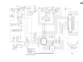
1. Course Computer PCB Circuit Description;Circuit diagram Fig. 1.
PCB assembly/parts list Fig. 2.
1.1. Power Supplies
Incoming power is routed to the PCB via the 'D' connector plug PL1. VI provides
suppression against any voltage spikes present on the incoming DC supply whilst D6
protects against reverse connection of the supply. 1C 1 is a 5V regulator and can
also reset the microprocessor, via TR9, should the supply voltage fall below 6V.
TR17, C19, D13, R92 and R91 form an 8V regulator to supply the windvane.
1.2. Microprocessor and Program Memory
IC2 is an Intel 80C32 microprocessor. It can access up to 32k bytes of program
memory (IC7) via the latch IC6. A clock signal for the microprocessor is provided by
an 11 MHz ceramic resonator (XL1) and associated capacitors C15 and C16. C14,
18 and 17 provide decoupling.
1.3. Analogue to Digital Converter
IC3,4,5 and 9 form a software driven analogue to digital converter. IC3 and IC9 are 8
channel multiplexed analogue switches routing all analogue signals, (see table
below), through to IC4 which is configured as an integrator. C9 is discharged at a
constant rate triggering the comparator IC5 as it reaches a level of approximately
0.53V. The output of the comparator is connected to the microprocessor thus
measuring the discharge time which is proportional to the analogue input.
Analogue Channels;IC3
Channel 0
IC9
2
Reset integrator
Channel 1
Channel 2
Channel 3
Channel 4
Channel 5
Channel 6
Channel 7
Integrator discharge signal
Fluxgate sense A
Fluxgate sense B
Motor Feedback 1
Motor Feedback 2
Windvane sense 1
Windvane sense 2
Channel 0
Alarm sense 1
Channel 1
Channel 2
Channel 3
Channel 4
Channel 5
Channel 6
Channel 7
Alarm sense 2
Rudder Reference
Supply Monitor
Rate Gyro sense
Gyro Compass sense
Joystick
Not used
SeaTalk Service Manual
Autohelm
1.4. Clutch Drive
TR10, 11 and 12 switch a nominal 12V onto the actuator clutch whenever pin 15 of
the microprocessor (IC2) is low at 0V.
1.5. SeaTalk Bus Transmit and Receive
SeaTalk transmit and receive circuitry consists of TR1, 2, 3,4, 5, 18 and 19 and their
associated components. Data Transmission is at 4800 baud with a low start bit and
line idling high. TR1 and TR2 provide high and low outputs respectively, whilst TR3
and Rl give overload protection to TR2 in the event of misconnection. TR4 and TR5
allow the microprocessor to monitor its own transmissions and also to receive data
from other units on the bus.
1.6. Fluxgate Drive
IC2 produces a series of 8KHz pulses on pin 2 which are then fed through TR6, 7
and 8 and AC coupled to the fluxgate via C3.
1.7 E2 Prom
IC8 is an e2 PROM (Electrically Erasable and programmable Read Only Memory)
which allows calibration values to be stored and recalled each time after power up.
Data is written to the e2 PROM on pin 3 and read back on pin 4.
1.8 Supply Voltage Monitor
R53 and R54 scale down the supply voltage and feed it through to the analogue to
digital convertor. This enables the microprocessor to transmit a warning on the
SeaTalk bus if the supply voltage drops below 11.2V (12V system) or 22.4V (24V
system) for 10 seconds or more.
1.9. Alarm Drive
The two main warning alarms are driven via TR13, 14, 15 and 16. Components
R41,42, 79,80 and D7 and 8 are used to detect any tampering with the alarm
connections, as required by the SFIA.
2. Power Amplifier PCB Circuit Description;Circuit diagram 12V-figure 3
Circuit diagram 24V - figure 3
PCB layout 12V-figure 4
PCB layout 24V-figure 5
The power amplifier electronics consist of three main areas;1. Voltage regulator 24V-12V. (Not present on 12V boards).
2. Reverse connection protection.
3. Current amplifier bridge.
2.1. Voltage Regulator (24V systems only)
TR13 and TR14 together with associated components form a 24-12V regulator
routing 12V to the course computer board via PL1.
SeaTalk Service Manual
3
Autohelm
2.2. Reverse Connection Protection
TR1 and TR2 along with RL1,2 and 3 ensure that external misconnection of Heavy
duty V+, Heavy duty 0V and M1 and M2 will not damage the unit.
2.3. Bridge Amplifier
TR6, 7,8 and 9 form a bridge amplifier to control the actuator motor. Four modes of
operation are possible, each selectable with a binary code on drive A and drive B.
Mode 1 - Drive A and drive B both a logic 1. The motor is shorted via TR7 and TR9.
This mode is used for stopping the motor quickly.
Mode 2 - Drive A and drive B both at logic 0. The motor is open circuit and therefore
may run as a generator allowing measurement of motor back emf. R14 and R16 in
combination with R25 and R28 on the computer PCB scale down the back emf.
Mode 3 - Drive A is at logic 1. Drive B is at logic 0. The motor will rotate clockwise.
Mode 4 - Drive B is at logic 1, drive A at logic 0. The motor will rotate anti-clockwise.
TR4 and TR10 are interlocks, switching off TR8 and TR6 when both drives are
switched high in mode 1. C3 and C20 suppress motor brush noise.
4
SeaTalk Service Manual
Autohelm
Fig. 1.
SeaTalk Service Manual
ST7000 (Z083 and Z084) Course Computer Circuit Diagram
ISS B
5
Autohelm
6
SeaTalk Service Manual
Autohelm
51
50
49
48
47
46
45
91063K9
940093061
1
1
WCR 1206 3K9 5X . 125W
EEPROM 16 x 16 M9306M 1 (SURFACE MOUNT)
R23
IC8
940374373
9400CA3130
94024051
940680C32
1
2
2
1
LATCH 74HC373
F.E.T. OP. AMP CA3130M (SURFACE MOUNT)
ANALOGUE SWITCH CD74HC405 1M1SURFACE MOUNT)
IC6
IC4, 5
IC3, 9
IC2
44
43
42
04049
05035
9500BC817
1
1
14
5v REGULATOR LM2925
TRANSISTOR PNP BDW94B
TRANSISTOR SOT23 NPN BC817
41
40
39
38
37
36
9500BC807
03067
93102U2
9307470P
931233P
93070U1
4
1
1
1
2
12
TRANSISTOR SOT23 PNP BC807
CAPACITOR TANTALUM 100uF ±20% 6V3 2.5 PITCH C6
CAPACITOR CASE A 2.2uF ±20X 6V3MIN
CAPACITOR 1206 470pF ±201 50v
CAPACITOR 1206 33pF ±5$ 50v
CAPACITOR 1206 0.1µF ±20* 50v
35
34
33
32
31
30
29
28
27
26
25
93161000P
2
CAPACITOR 1206 1000pF ±2% COG 50v
C1, C9
02031
9200BAS19
9200BAS16
1
1
9
DIODE MR751 (MOTOROLA)
DIODE SOT23 BAS19
DIODE SOT23 BAS16
D6
D12
D2, 3, 4, 5, 7, 8, 9, 10, 11
91063R3
9106470K
910382R
91035K6
910368K
2
1
1
3
13
WCR 1206 3R3 5% .125W
WCR 1206 470K 5% .125W
WCR 1206 82R 5% .125W
WCR 1206 5K6 5% .125W
WCR 1206 68K 5% .125W
R87, 88
R68
R62
R53, 59, 90
MICRO ROM LESS 8032 12MHz PLCC NMOS
OR 80C32 12MHz PLCC CMOS
52
53
54
55
56
57
58
910333K
91036K8
910310K
910668R
930522N
9203BZX9V1
15036
2
2
3
1
1
1
1
WCR 1206 33K 1% .I25W
WCR 1206 6K8 1% .125W
WCR 1206 10K 1% .125W
WCR 1206 68R 5X .125W
CAPACITOR 1206 22nF ±5% X7R 50V
ZENER DIODE SOT23 BZX 84C9V1
TRANSISTOR MOUNTING PAD
R30.43
R37 38
R39.40.49
R92
C5
D13
IC1
TR12
TR2, 3, 4, 5, 6, 7, 9, 10, 11, 13,14,
17, 18, 19
TR1, 8, 15, 16
C3
C20
C15, 16
C2, 4, 7, 8, 10, 11, 12, 13, 14, 17,
18, 19
R33, 34, 35, 36, 41, 42, 44, 45, 46,
47, 48, 63, 89
24
23
22
21
20
19
18
17
16
15
14
13
12
11
10
9
8
7
6
5
4
3
2
1
9103270R
91031K
3
6
WCR 1206 270R 5% .125W
WCR 1206 1K 5% .125W
R28, 29, 65
R26, 27, 31, 32, 54, 64
91061K5
91034K7
91064K7
910615K
910610K
910622K
91062K2
91061K8
91031K2
91061K2
9106390R
910639K
91068R2
01051
26005
15085
15033
07164
07155
07118
3015-030
3
2
3
1
13
1
6
2
5
WCR 1206 1K5 5% .125W
WCR 1206 4K7 5% .125W
WCR 1206 4K7 5% .125W
WCR 1206 15K 5% .125W
WCR 1206 10K 5% .125W
WCR 1206 22K 5% .125W
WCR 1206 2K2 5% .125W
WCR 1206 1K8 5% .125W
WCR 1206 1K2 5% .125W
R16, 18, 91
R73, 74
R12, 75, 76
R10
1
3
5
1
2
1
2
1
1
1
1
WCR 1206 390R 5% .125W
WCR 1206 39K 5% .125W
WCR 1206 8R2 5% .125W R1, 20, 21. (691,70,71, (72)
VAR1STOR ZNR TYPE D ERZC07DK270
RIVSCREW (1712-35091
CERAMIC RESONATOR 11MHz CERALOCK CSA 11.OMT XL1
HEATSINK
1C SOCKET (28 PIN)
16 WAY HEADER
'D 'CONNECTOR 25 WAY
7000 COMPUTER P.C.B DETAIL
R3
R2, 11, 13
ITEMS
DR'G/PART N*
QTY
DESCRIPTION
R8
R6, 7, 83, 84, 85, 86
R77, 78
R4, 5, 17, 19, 61
SEE NOTE
V1
SKT1
PL2
PL1
Fig. 2.
SeaTalk Service Manual
Z083 and Z084 Course Computer PCB Assembly/Parts List
ISS G
7
Autohelm
8
SeaTalk Service Manual
Autohelm
Z083 Power Amplifier Circuit Diagram 12V
Z084 Power Amplifier Circuit Diagram 24V
Fig. 3.
SeaTalk Service Manual
9
Autohelm
10
SeaTalk Service Manual
Autohelm
21
20
19
18
17
16
15
14
13
\?
11
10
9
8
7
6
5
4
3
2
1
ITEMS
03031
01083
15057
13024
05019
05018
03036
03023
03020
02004
02002
01158
01157
01102
01061
01055
01045
01032
01003
4021-024
4021-023
DR'G/PART N*
f
1
3
1
4
4
2
1
2
4
1
4
2
?
3
t
4
4
1
1
1
Q'T'Y
CAPACITOR ELECTROLYTIC 100uF +80% -20% 25VMIN C6
RESISTOR C’FILM 3K9 .25W ±5%
R3
RELAY T90.30A
RL1, 2, 3
LINK
LK1
TRANSISTOR PNP BC 327
TR4, 5, 10, 11
TRANSISTORS BC 337
TR1, 2, 3, 12
CAPACITOR TANTALUM 1µF ±20%
25vmin C3, 20
CAPACITOR ELECTROLYTIC 1000µF +80% -20% 60vmin C5
CAPACITOR CERAMIC 0.01µF ±20%
25vmin C2, 4
DIODE IN 4148
D2, 3, 5, 6
DIODE IN 4818
D8
RESISTOR CTILM 1K5 .25W ±5%
R7, 9, 20, 22
RESISTOR WIREWOUND 82R 2.5W ±5%
R12. 18
RESISTOR CTILM IK .25W ±1%
R14. 16
RESISTOR CTILM 6K8 .25W ±5%
R5, 6, 24
RESISTOR CTILM 270R .5W ±5%
R15
RESISTOR CTILM 220R .25W ±5%
R11, 13, 17, 19
RESISTOR CTILM ZK2 .25W ±5
R8, 10, 21, 23
RESISTOR CTILM IK .25W ±5%
R4
LOOM S'ASSY
POWER AMP. S'ASSY 1st STAGE
DESCRIPTION
Fig. 4.
SeaTalk Service Manual
Power Amplifier PCB Assembly/Parts List (Z083)
ISS B
11
Autohelm
12
SeaTalk Service Manual
Autohelm
24
23
22
21
20
19
18
17
16
15
14
13
12
11
10
9
8
7
6
5
4
3
2
1
ITEMS
15057
05019
05018
03036
03031
03023
03020
03007
02025
02004
02002
01162
01140
01139
0112?
01083
01061
01055
01045
01031
L01006
01003
4021-028
LJ402 1-024
DR'G/PART Ne
3
4
5
2
2
5
3
1
4
i
4
2
1
1
QTY
RELAY T90 30A
RL1, 2, 3
TRANSISTOR PNP BC 327
T4, 5, 10, 11
TRANSISTOR NPN BC 337
T1, 2, 3, 12, 13
CAPACITOR TANTALUM 1µF±20% 25vmin C3, 20
CAPACITOR ELECTROLYTIC 100% 525vmin C6
CAPACITOR ELECTROLYTIC 1000µF
60vmin C5
CAPACITOR CERAMIC 0.01µF ±20%
25vmin C2.4
CAPACITOR CERAMIC 0.1µF ±20% 25vmin C1
ZENER DIODE BZX 6 1C 15V
D9
DIODE IN 4148
D2, 3, 5, 6
DIODE IN 4818
D8
RESISTOR WIREWOUND 330R 2.5W+5% R12, 18
RESISTOR C'FILM 120R 2.5W ±10%
R2
RESISTOR C'FILM 680R .5W ±5%
R26
RESISTOR C'FILM 6K8 .25W +1%
R14, 16
RESISTOR C'FILM 3K9 .25W ±5%
R3, 7, 9, 20, 22
RESISTOR C'FILM 6K8 .25W ±5%
R5, 6, 24
RESISTOR C'FILM 270R .5W ±5%
R15
RESISTOR C'FILM 220R .25W ±5%
R11, 13, 17, 19
RESISTOR C'FILM 560R .25W ±5%
R1
RESISTOR C'FILM 5K6 .25W ±5%
R8, 10, 21, 23
RESISTOR C'FILM 1K .25W ±5%
R4, 25
POWER AMP. S'ASSY 1st STAGE
LOOM S'ASSY
DESCRIPTION
Fig. 5.
SeaTalk Service Manual
Power Amplifier PCB Assembly/Parts List (Z084)
ISS B
13
Autohelm
14
SeaTalk Service Manual
Autohelm
Colour code
Sc
White
R
Red
G
Green
Y
Yellow
B
Blue
Br
Brown
SK1
Fig- 6.
SeaTalk Service Manual
Connector PCB Circuit Diagram (Z083f Z084)
ISS A
15
Autohelm
16
SeaTalk Service Manual
Autohelm
3
07163
2
07119
1
3015-029
ITEMS DR'G/PART N*
4
1
1
QTY
TERMINAL BLOCK
'D' CONNECTOR
PCB DETAIL
DESCRIPTION
Fig. 7.
SeaTalk Service Manual
Connector PCB General Assembly
ISS C
17
Autohelm
18
SeaTalk Service Manual
Autohelm
ST6000 System
1. Service Procedures
SeaTalk Service Manual
1
Autohelm
Contents
1.
2.
3.
3.1
3.2
3.3
3.4
3.4.1
3.4.2
3.5
4.
5.
5.1
5.2
5.3
5.4
6.
6.1
6.2
6.3
7.
7.1
2
Introduction
System Description
Operating / Calibration Instructions
Operation
Addition information for sailing vessels
Operating Hints
Calibration
Adjusting Calibration
Display Contrast Adjustment
Fluxgate Compass – Automatic Deviation Correction
Common system problems
Track control interfacing
Inverted data
Conversion of units
Alarm messages
NMEA Data input format
Special functions
Display of software version
Permanent watch alarm mode
Display Test mode
Service Visit to a Vessel
Onboard diagnostics
SeaTalk Service Manual
Page
3
3
4
4
10
12
15
16
17
18
19
19
19
19
19
20
21
21
21
21
23
23
Autohelm
1. Introduction
The ST6000 system section of this manual contains full system operating instructions
and service procedures for the autopilot. Further in depth diagnostics are available
for each module in the relevant product sections.
2. Systems description
The ST6000 is a modular Seatalk compatible autopilot system that can be built up to
match the individual requirements of most vessels and steering systems.
The ST6000 course computer can be used with all Seatalk compatible control units
and ST50 instruments and will operate the following drive units:
Z039 Linear drive type 1
Z037 Rotary drive type 1
Z041 Hydraulic pump type 1
Z081 Hydraulic pump type 0
Z088 I/O Sterndrive
Z064 Type CR 3L/min (via Z085 Interface)
Z066 Type CR 4.5L/min (via Z085 Interface)
SeaTalk Service Manual
3
Autohelm
3. Operating/Calibration Instructions
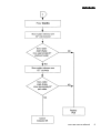
3.1 Operation
Automatic Heading
Auto
Push to engage automatic
steering and maintain current
heading.
OR
Push and hold down for 1 Previous Automatic Heading
second to return to previous
automatic heading. (Display
returns to Auto after 10
seconds).
New Automatic Heading
Course Changes (-1, +1, -10, +10)
Push to alter course to port (-)
and
starboard
(+)
in
increments of 1 and 10
degrees.
Current Heading
Standby
Push to disengage the
autopilot for manual steering
(The previous automatic
heading is memorised).
Track (see operating hints)
Push to select track control
from Auto.
Push again to return to
automatic steering.
OR
Push and hold down for 1
second to select previous track
control heading from Auto or
Track.
(Display returns to Track after 10 seconds).
4
SeaTalk Service Manual
Automatic Heading
Autohelm
Response
•
Response Level
Response Level Adjustment (see Operating Hints)
Push to increase (▲) or decrease
(▼) response level.
To display response level without
changing it push both Response
keys together briefly.
•
Rudder Gain Level
Rudder Gain Adjustment (see Operating Hints)
Push and hold down for 1 second
both Response keys together to
display rudder gain level.
Within 10 seconds push once to Rudder Gain Level
increase (▲) or decrease (▼)
ruddergain.
(Response and Rudder levels are displayed for 10 seconds
only)
Illumination Level
Illumination
Push and hold down Display for 1
second to switch on illumination.
Within 10 seconds push Display to
select illumination level.
3
2
1
OFF
= High
= Medium
= Low
= 0ff
(Illumination level is displayed for 10 seconds only)
SeaTalk Service Manual
5
Autohelm
Display Key Sequence
Auto Mode
The Display pushbutton is used to cycle
•
through additional information menus.
These menus depend on the autopilot mode
and if navigation information is available.
Main Display
Standby Mode
•
Main Display
•
Compass Heading
•
Rudder Angle
•
Rudder Angle
•
Navigation Displays
See section on Navigation Displays.
•
•
Navigation Displays
See section on Navigation Displays.
6
SeaTalk Service Manual
Watch Alarm
Autohelm
Track Mode
Navigation Displays
•
Main Display
With the Navigation Receiver operating in
waypoint mode, the following information can
be displayed (provided that the Navigation
Receiver transmits the appropriate
information - see Installation Handbook).
•
Locked Course
•
Rudder Angle
•
Cross Track Error
The arrows show the direction to steer to
rejoin the desired Track:
► Starboard
◄ Port
•
•
Bearing to Waypoint
Navigation Displays
•
Magnetic
•
True
See section on Navigation Displays.
•
•
Distance to Waypoint
•
Waypoint Number
Watch Alarm
SeaTalk Service Manual
7
Autohelm
Watch Alarm (not available in Standby)
Warning Messages
• Engage the Autopilot in Auto Track •
Windvane mode.
• To select Watch alarm push Display
repeatedly until Watch appears.
Off Course Alarm
— Sounds if the vessel deviates from the
automatic heading by more than the
The 4 minute timer is now running:— After 3 minutes 'Watch' flashes on all selected amount for over 20 seconds.
control units.
— After 4 minutes the alarm sounds on all • Low Battery Alarm
control units.
• Push Auto at any time to reset the timer
to 4 minutes and silence the alarm.
• To cancel the Watch alarm at any time
— Sounds if the course computer supply
push Display.
voltage falls below 11 volts for over 20
seconds.
•
Track Mode Alarms
— Sounds if no waypoint data is received
from the Radio Navigation System for over
20 seconds.
— Sounds if the data has the incorrect
format or if an invalid flag is set.
— Sounds if the cross track error exceeds
0.30n.m.
8
SeaTalk Service Manual
Autohelm
— Sounds when the target waypoint number changes. The displayed bearing is to
the new waypoint. PORT or STBD indicates in which direction the autopilot will turn
onto the new waypoint bearing.
Push Track to silence the alarm and automatically steer onto the new bearing to
waypoint.
• Manual Override Alarm
(Installations with stern drive actuators only).
— Sounds for 10 seconds when the autopilot is manually overridden at the steering
wheel. After 10 seconds the autopilot will return to Standby automatically.
Note: Push Standby to silence an alarm and select Standby mode (unless indicated
otherwise).
SeaTalk Service Manual
9
Autohelm
3.2 Additional information for Sailing Vessels
Autotack
The ST6000 has a built in Autotack function
which will turn the vessel through 100°. This
operates in both compass and vane modes
as follows:Vane
Push +1 and +10 keys
together to initiate a tack
turning to Starboard.
Push –1 and –10 keys
together to initiate a tack
turning to Port.
Note: It is important that the rudder angle
transducer is accurately aligned as the
Autotack function mirrors standing helm and
any offset will change the initial tack angle.
Wind Trim (Windvane Operation)
Wind Trim allows the autopilot to be
supervised by apparent wind direction. The
wind direction is read either:— From the SeaTalk bus (requires
Autohelm ST 50 unit).
OR
— From an NMEA 0183 input on the control
unit.
Push both red keys together Automatic Heading
to select Wind Trim and
maintain
the
current
apparent wind angle.
Previous Automatic
Push and hold down for 1
second both red keys Heading
together to return to the
previous
apparent
wind
angle.
10
SeaTalk Service Manual
Autohelm
Wind Change Alarm
Wind Trim uses the fluxgate compass as
the primary heading reference and
automatically adjusts the compass heading
to maintain the original apparent wind angle.
If changes in apparent wind angle adjust the
original automatic heading by more than 15°
the wind change alarm will sound.
— The alarm is silenced by pushing both
red keys together briefly.
Using Wind Trim
It is important to understand that "Wind
Trim" prevents over-reaction to gusts or
sudden wind shifts. One minute is required
to change the heading in response to a
permanent change in apparent wind angle.
Do not attempt to override the automatic
sequence with the course change buttons.
In gusty conditions sail a few degrees off
the wind and pay frequent attention to sail
trim and helm balance using the rudder
angle indication.
Performance will normally be improved by
reefing headsail and mainsail a little early
rather than too late.
Display of Wind Angle
If the wind angle information is supplied
using the NMEA 0183 input or SeaTalk bus,
the apparent wind angle and tack sense (◄
for port, ► for starboard) is added to the
display menu and accessed via the Display
button.
•
Apparent Wind Angle
— The apparent Wind Angle is 35° —
Starboard Tack.
•
Adjust Apparent Wind Angle
Use the ±1 or ±10 degree
buttons to change heading
and hence adjust the
apparent wind angle.
SeaTalk Service Manual
11
Autohelm
This accepts the new target waypoint and will
steer the vessel onto the new bearing to
waypoint.
Response Level Adjustment
The tidal offset may be very different on the new
The ST6000 has three response levels which bearing, and it is good practise to check the
enable tighter course keeping to be achieved in cross track error after a couple of minutes. If the
certain cases:cross track error continues to increase make a
Level 1 - Automatic Sea State Control
course adjustment of say 10 degrees in the
Level 2 - Automatic Sea State Inhibit
direction of the arrow. This will help the Track
Level 3 - Automatic Sea State Inhibit and
control correct more quickly for the new tidal
counter rudder.
vector.
When the autopilot is switched on, the response
level is set to 1. This provides the best Automatic Trim
compromise between power consumption and If Automatic Trim has been selected during
course keeping accuracy and is suitable for calibration the ST6000 will correct for trim
nearly all situations.
changes. This correction can take up to one
Increasing Response level provides tighter minute to apply the rudder offset necessary to
course keeping at the expense of increased restore the set automatic heading. Large course
power consumption and general wear and tear. changes which change the apparent wind
It is advisable to use the minimum response direction, can produce large trim changes. In
level necessary to achieve the desired course these cases the autopilot will not immediately
keeping accuracy. On larger power vessels assume the new automatic heading, and only
level 3 can improve slow speed steering where settle onto course when the Automatic Trim has
the natural yaw damping of the vessel is been fully established.
reduced.
To minimise the inherent time delay the
Note: Level 3 is not recommended for use at following procedure may be adopted for large
planing speeds or in rough seas.
course changes.
• Note required new heading.
Track
• Select Standby and steer manually.
To make full use of Track control the following • Bring vessel onto new heading.
simple points should be observed:• Select Auto and let vessel settle onto
• Always steer the vessel to within 0.1nm of course.
track and bring the heading to within 5° of the • Bring to final course with 1° increments.
bearing to the next waypoint before selecting It is sound seamanship to make major course
Track.
changes only whilst steering manually. In this
• Always check that there are no navigational way any obstructions or other vessels may be
hazards either side of the intended track.
cleared properly and due account taken of the
• Always maintain an accurate log with changed wind and sea conditions on the new
regular plots to verify the computed position heading prior to engaging the autopilot.
read from the Radio Navigation Receiver.
• Maintain a proper lookout at all times.
Rudder Gain
•
The rudder gain level selected during initial sea
Waypoint Advance
trials will normally provide excellent steering
If the navigation receiver is transmitting the performance over a wide range of conditions.
waypoint number to the ST6000 the waypoint However, it may be noticed that the autopilot
alarm will sound whenever a new target tends to be a little less stable on northerly
waypoint is selected (see Page 9). When the headings in the higher latitudes of the northern
alarm is sounding the ST6000 will maintain the hemisphere (and conversely southerly headings
current heading and automatic track control is in the southern hemisphere). This is caused by
suspended. Check the displayed new bearing to the increasing angle of dip of the earth's
waypoint and when it is safe to turn onto it,
resume automatic track control by simply
pushing Track.
3.3 Operating Hints
12
SeaTalk Service Manual
Autohelm
magnetic field at higher latitudes which has
the effect of amplifying rudder response on
northerly (southerly) headings.
Rudder Gain Adjustment (Sail) It is not
normally necessary to adjust the autopilot
gain setting once the correct level has been
established during initial sea trials.
Depending on the yachts individual steering
characteristics a change of one level may
improve course keeping accuracy when
going from northerly to southerly (increase)
or southerly to northerly (decrease)
headings.
The effect may be judged by carrying out a
sea trial in smooth water conditions and
observing the results.
Note: The effect is reversed for the
southern hemisphere.
Rudder Gain Adjustment (Powercraft) The
tendency towards northerly (southerly)
heading instability is more obvious in high
speed craft and can be corrected by a
reduction in the rudder gain setting. At
speeds in excess of 30 knots a reduction of
two levels can be required on headings
between
315°
and 045° (northern
hemisphere) or 135° and 230° (southern
hemisphere).
Two options are available to control this:• Manual (Low speed and displacement
craft) The rudder gain control may change
by one level when going from northerly to
southerly (increase) or southerly to northerly
(decrease) headings.
The effect may be judged by carrying out a
sea trial in smooth water conditions and
observing the results.
Note: The effect is reversed for the southern
hemisphere.
• Autoadapt (High speed planing craft)
The ST6000 can be set to automatically
reduce the effects of Northerly heading
instability. This feature is selected in
calibration mode by entering the Latitude
(see Installation Handbook, Calibration,
section on 'Auto Adapt'). When selected the
ST6000 automatically adjusts the Rudder
Gain depending on the compass heading,
removing the need for manual adjustment.
Rudder
Gain/Speed
Adjustment
(Powercraft)
High speed planning craft exhibit very
different steering characteristics when on
and off the plane. As a result it is generally
necessary to adjust the Rudder Gain setting
when going from displacement speed to
planing speed or vice versa. Two options
are available to achieve this:• Automatic
When the ST 6000 is used with an
Autohelm ST50 Speed Instrument or
Tridata.
Rudder
Gain
is
adjusted
automatically with boat speed. There should
be no need for any manual adjustment.
• Manual
(No ST50 Speed/Tridata) The Rudder Gain
setting may be increased by one or two
levels when dropping from planing speed to
cruise speed and decreased by the same
amount when returning to planing speeds,
Note: It is important to make the gain
adjustment after dropping to displacement
speed and before returning to planing
speed.
Note: The adjustment of Gain with boat
speed is normally only required for high
speed planing powercraft.
Unsatisfactory Steering Performance
If the ST6000 has been installed and set up
in accordance with the instructions in the
Installation Manual it will provide excellent
steering performance over a wide range of
conditions.
If performance drops but the autopilot is still
working correctly, the following simple
checks should find the fault:• Has a magnetic influence been
introduced near the fluxgate compass? i.e.
anchor,
chain,
radio
equipment,
loudspeaker, tools. generator etc. Check
that the autopilot compass heading still
corresponds with the steering compass.
• Are all fuses intact, circuit breakers
engaged?
• Are all screw connections tight and free
of corrosion.
SeaTalk Service Manual
13
Autohelm
• If the autopilot fails to hold course check
the Rudder Gain level. Has it been changed
from the initial sea trials level (check in
Installation Manual)?
• If the vessel wanders check that the
Rudder Reference Transducer linkage is
secure with no free play.
Hydraulic Drive Units only:• Check that all unions are tight and bleed
system to remove air.
Failure of Drive Unit to Disengage
The mechanical drive actuators of the
ST6000 are designed to fail Safe1 - When
power is disconnected the drive unit will
disengage leaving the steering system free
for manual control.
When Standby is selected the actuator will
Disengage leaving the steering free.
It is remotely possible that a fault could
develop which could cause the actuator to
remain engaged even when Standby is
selected. If this happens:• DISCONNECT THE MAIN CIRCUIT
BREAKER TO THE AUTOPILOT - THE
STEERING WILL IMMEDIATELY BE FREE,
or
• IN AN EMERGENCY THE ACTUATOR
CLUTCH
CAN
NORMALLY
BE
OVERRIDDEN
BY
TURNING
THE
STEERING WHEEL HARD.
It is emphasised that this fault is extremely
unlikely and can be immediately corrected
as described.
If preferred a separate Override switch can
be fitted close to the steering position which
will break the actuator clutch drive for
Emergency Use.
14
SeaTalk Service Manual
Stern Drive Actuator
(Manual Override Option)
Manual override is selected during
calibration using the Auto Release option. It
must only be used on installations fitted with
the stern drive actuator. When it has been
selected, the ST6000 can be overridden to
allow hand steering by turning the steering
wheel. This will return the ST6000 to
Standby and sound the control unit buzzer
for 10 seconds. There is a slight delay
before the ST6000 will return to Standby.
Excessive force is not required and will
not reduce this delay.
With the ST6000 in Auto and clear of
obstruction turn the steering wheel to
observe the manual override. Repeat two or
three times until you are confident with its
operation.
The manual override is intended for
emergency use only. The ST6000 should
normally be disengaged by pushing the
Standby button on the control unit.
Autohelm
3.4 Calibration
Recommended Settings
As supplied the ST6000 can be switched on
and tested safely without any adjustments
to the factory calibration settings.
The table below lists the suggested settings
for sailing and power displacement and
planing power vessels. These will provide
good performance for initial sea trials and
can be fine tuned later to optimise
performance.
Vessel Type
Displacement
Planing
Factory preset
Set to
Rudder Gain
(level)
Rate Gain
(level)
Rudder Angle
Limit (degrees)
Turn Rate Limit
(degrees/sec)
Cruise Speed
(knots)
Off Course
Alarm (degrees)
Trim Level
Auto Adapt
Drive Type
Rudder
Position
Deadband
(level) See
3.8
Auto
Release
5
2
2
1
30
30
20
5
8
25
20
1
OFF
20
1
ON
Selecting and Exiting from Calibration Mode
To select calibration mode:• Push Standby.
• Push and hold down for 2 seconds,
Track and Display together.
• Repeat push and hold down for 2
seconds, Track and Display together to
enter calibration mode.
To exit calibration mode at any point;
a) Saving any changes made:• Push and hold down for 2 seconds,
Track and Display together.
b) Ignoring any changes made:• Push Standby.
Autopilot Drive Unit Type
Mechanical Stern Hydraulic
Drive
Factory
Set to
Set to
preset
3
3
4
1
1
OFF
1
ON
OFF
SeaTalk Service Manual
15
Autohelm
3.4.1 Adjusting Calibration
•
In calibration mode, the Display button is
used to scroll through the menu. The
displayed value is adjusted using the
Response buttons (hold button down for fast
scroll).
Rate of Turn Limit, 5° to 20°/sec.
• Cruise Speed, for Track mode
operation, 4 to 60 knots.
•
16
Off-Course Alarm, 15° to 40° angle.
•
Automatic Trim, (see 5.4).
Rudder Gain, levels 1 to 9, (see 5.6)
• Rate Gain, levels 1 to 9, (see 5.7)
(Counter Rudder).
•
•
Rudder Angle Limit, 15° to 40° (see 3.6).
SeaTalk Service Manual
• Remote Control Identifier. (For Future
Use).
Autohelm
Autopilot Drive Unit Type.
1 = Future Use
2 = Future Use
3 = Mechanical with Rudder Reference
4 = Hydraulic with Rudder Reference
• Rudder Position Deadband (levels 1 to
9), (See 3.7).
and in the Southern Hemisphere.
•
Auto Release (see 3.8).
0 = OFF
1 = ON
The Auto Release facility is designed to
provide Emergency Manual Override when
used with the Autohelm Stern Drive
Actuator.
For all other Drive Systems Auto Release
must be selected "OFF" (0).
3.4.2 Display Contrast Adjustment
•
Northerly/Southerly Heading Instability
Select Hemisphere
N (North)
S (South)
The LCD Contrast can be adjusted to suit a
wide range of control unit viewing angles.
• Push display and track together
momentarily.
• Push response ▲ to increase contrast
(suits viewing from below),
• Push response ▼ to decrease contrast
(suits viewing from above).
• Adjust the display for optimum viewing.
• Push display and track together
momentarily to store selection and return to
previous operating mode.
Enter Local Latitude using Response Keys.
Atypical display in the Northern Hemisphere
would be:
SeaTalk Service Manual
17
Autohelm
3.5 Automatic Deviation Correction
The ST6000 will correct the fluxgate compass for operation in most deviating
magnetic fields. This should be carried out in calm conditions preferably in flat water.
• To select compass adjust Push and hold Standby for 1 second.
Keeping boat speed below 2 knots, turn the vessel slowly so that it takes at least 3
minutes to complete 360°. Keep turning until control unit beeps, and the display
changes to show the amount of deviation the autopilot has corrected:-
Note: If the amount exceeds 15°, it is recommended the fluxgate should be re-sited.
• Use the course change buttons to adjust the displayed heading until it agrees with
the steering compass or a known transit bearing.
Note: 000° is always followed by OFF. This will suppress the display of compass and
automatic headings on the control unit.
• To exit compass adjust and store the compass settings push and hold Standby
for 1 second.
• To exit compass adjust without saving any new settings push Standby
momentarily.
18
SeaTalk Service Manual
Autohelm
4. Common system problems
Problem
Cause
Solutions
To be updated as necessary
“
“
“
“
5. Track control interfacing
In most cases interfacing the ST6000 to either a GPS, Decca, Loran or Satellite
Navigation system is a simple and straight forward task so long as the requirements
set out in section 6 of the installation manual are met. There are however a few
exceptions.
5.1 Inverted Data
Some receivers, notably some of the Furuno range and early Navstar models,
transmit data in an inverted format with respect to 5V. This is easily seen as the data
line will idle high with respect to 0V in between data transmissions. In these cases
the NMEA cable on the rear of the control unit must be wired with the red wire
connected to 5V (this is normally available on the receiver terminal block), and the
blue wire connected to the data line.
5.2 Conversion of Units.
All data containing units of distance will be converted to Nautical miles by the Control
Unit. Therefore any receivers displaying Cross Track Error or Distance To Waypoint
in either Kilometres of Statute miles etc will have their data displayed on the control
unit in Nautical miles.
5.3 Alarm Messages
Track mode has 3 alarm messages:1. No data
If a standard NMEA sentence is not received by the ST6000
2. Data error The ST6000 has recognised the incoming data as NMEA but has
detected an invalid flag. This is normally due to poor signal strength at
the receiver.
3. Large XTE Cross track error greater than 0.3NM.
Errors 1 and 2 can provide valuable information as to where an installation problem
might lie. The 'No data' message indicates the ST6000 is not receiving NMEA data
and carries a high probability of a wiring error between the receiver and the pilot. The
'data error’
SeaTalk Service Manual
19
Autohelm
message indicates the ST6000 is receiving data recognised as NMEA but has an
invalid flag set. This is normally due to the receiver having a low signal strength or a
high noise figure.
5.4 Autohelm 6000 NMEA 0183 data input format
The 6000 must receive Cross Track Error data at least once every 30
seconds.
If a display of Waypoint Bearing, Distance or Number or the Waypoint
advance facility is required then this information must be received at
least once every 30 seconds.
All NMEA data is read into a buffer thus enabling the 6000 to cope
with delays between characters and delays between sentences.
All Talker identifier characters, ie RA, DE, LC etc. are ignored allowing
interface with any type of equipment so long as the sentence type is
one of the following :Apparent wind speed and angle can be received from any external equipment
transmitting the N.M.E.A VWR header. The ST6000 will only display apparent wind
angle but will convert and retransmit both apparent wind speed and direction on the
seatalk bus. This information can then be displayed on an ST50 wind instrument
acting as a repeater.
Track
Control
XTE
XTR
APA
APB
RMB
20
Bearing to
Waypoint
APB
BPI
BWR
BWC
BER
BEC
RMB
SeaTalk Service Manual
Distance to
Waypoint
WDR
WDC
BPI
BWR
BWC
BER
BEC
RMB
Waypoint
Number
APB
APA
BPI
BWR
WDR
BWC
WDC
RMB
BOD
WCV
BER
BEC
Apparent Wind
Speed and Direction
VWR
Autohelm
6. Special Functions
6.1 Display of Software Version
It is possible to display the version number of both course computer and control unit
software installed in a particular system. This is achieved by pressing both the +10
and -10 keys together for 2 seconds and releasing the display will show the control
unit version (65 followed by version number) for 10 seconds followed by the course
computer version (66 followed by version number). The pilot must be in standby
mode at the time. Each version is displayed for 10 seconds before the pilot reverts
back to standby. A software history for each product is shown in the relevant service
sections.
6.2 Permanent Watch Alarm Mode
The ST6000 autopilot can be set up with a permanent watch alarm mode, as required
by the Sea Fish Industry authority (SFIA).
It must be stressed that the selection of this mode is permanent and can only
be reversed by returning the course computer to Nautech.
Permanent watch alarm is achieved by first entering the calibration menu. Once in
calibration, regardless of display message, press the Auto, Standby, and Track keys
together for 1 second before releasing. The display will now show 'SELECT WATCH'.
The user now has 10 seconds to select permanent watch alarm mode by again
pressing Auto, Standby and Track together for 1 second. The display will then show
'WATCH ON1 for 10 seconds before reverting back to 'CAL1. A normal exit from
calibration mode must now be executed.
6.3 Display Test Mode
All display segments on the control unit can be switched on by pressing the +10, -10,
Standby and Display keys together. This mode can only be accessed after the unit
has been powered up with the yellow data wire open circuit.
SeaTalk Service Manual
21
Autohelm
7. Service visit to a vessel
When a service visit to a vessel is made the most common fault encountered is likely
to be poor connections or inadequate power supplies. These should be thoroughly
checked before the service visit diagnostic procedure is carried out. When trying to
locate a fault it should be remembered that most failures will occur in the Course
Computer with the Control Units as the next most likely.
It should be noted that the calibration variables and auto deviation correction will
require re-setting if either the course computer, its PCB or its Software are
exchanged. Similarly if the Control Unit PCB is exchanged the display contrast will
require re-setting. Procedures for carrying out both these operations are given in
section 3.
Always note the course computer calibration settings before removing from the
vessel.
22
SeaTalk Service Manual
Autohelm
7.1 Service Visit - Diagnostic Procedure
On arrival check for bad connections and for inadequate power supplies. If the system still
exhibits a fault, then use the diagnostic procedure outlined below.
SeaTalk Service Manual
23
Autohelm
24
SeaTalk Service Manual
Autohelm
ST6000 Control Unit (Z124)
1. Service Procedures
2. Technical Information
SeaTalk Service Manual
1
Autohelm
1. Service Procedures
Contents
1. Description
2. Dismantling
3. Reassembly
4. Display Contrast Adjustment
5. Functional Test
6. Product History
7. Software History
8. Spares Numbers
Page
3
3
3
4
6
8
8
8
Illustrations
Fig. 1. General assembly
5
2
SeaTalk Service Manual
Autohelm
1. Description
The Z124 control unit is Seatalk compatible and consists of a single PCB built using
surface mount technology. The unit can be functionally tested (figure 3) without the
use of special equipment other than a seatalk cable with a seatalk plug at one end
and bared cores at the other.
If a control unit or its PCB are replaced the display contrast will require re-setting.
This should be carried out aboard the vessel following the instructions given in
section 3.
2. Dismantling
After removing the unit from the boat and returning to the service centre. Place face
down on a clean, light foam surface. Preferably conductive.
1. Unscrew and remove the 4 case securing screws from the rear cover. Push each
cable loom assembly back through its grommet so as to obtain working clearance to
the PCB (fig 1)
Note: if cables are very tight in grommets apply a small smear of silicon grease to
outer sheath, (grease can be wiped off after reassembly).
If removing the PCB assembly it will be necessary to de-solder the cables from the
PCB. Great care should be exercised when de-soldering so as not to damage the
pads on the PCB.
2. Unscrew and remove the 9 screws which secure the PCB to the facia.
Note: Do not at this stage remove the screws which secure the LCD assembly to the
PCB. Refer to figure 1 to clarify which screws to remove.
3. Before removing the LCD ensure that lint free and preferably anti static finger cots
are worn to prevent the LCD or elastomers getting dirty or greasy.
4. Unscrew and remove the 3 LCD housing retaining screws (fig 1). Be careful to hold
the LCD surround, LCD, and diffuser when dismantling. Lift away from the PCB and
store.
3. Re-assembly
Re-assembly is a straight reversal of the above procedure but note the following
points:1. Ensure the LCD is correctly orientated relative to the PCB (fig 1).
2. Ensure the diffuser is correctly orientated relative to the LCD and PCB (fig 1).
3. Note the correct orientation of the various looms and core colours to the PCB pads
(fig 1).
4. Ensure that the board is tightened down sequentially to ensure the load is evenly
spread.
SeaTalk Service Manual
3
Autohelm
5. Pull the loom assemblies back through the grommets when lowering the cover to
ensure that the cables do not bunch up inside the cover and foul the PCB on reassembly.
6. Refit the cover.
7. Re-check for full function after re-assembly to check the LCD has not been
damaged or looms incorrectly soldered. Adjust LCD contrast if necessary.
4. Display Contrast adjustment
The LCD Contrast can be adjusted to suit a wide range of control unit viewing angles.
Push display and track together momentarily.
Push response ▲ to increase contrast (suits viewing from below).
Push response ▼ to decrease contrast (suits viewing from above).
Adjust the display for optimum viewing.
Push display and track together momentarily to store selection and return to previous
operating mode.
4
SeaTalk Service Manual
Autohelm
Fig. 1.
SeaTalk Service Manual
5
Autohelm
4. Z124 Control Unit Functional Test
6
SeaTalk Service Manual
Autohelm
SeaTalk Service Manual
7
Autohelm
5. Product History - Control Unit (2124)
Change
Serial number
030001
Comments
production start
6. Software History - Control Unit (Z124)
Version
65E
Change
Product launch
Serial No
030001
7. Spares numbers - Control unit (Z124)
Item
Double skin mounting kit
PCB assembly
LCD
Protective cover
8
SeaTalk Service Manual
Catalogue no
Q003
Q027
Q028
D123
Comments
allows fixing to up to 4" thick bulk heads
Autohelm
2. Technical Information
Contents
1. Circuit Description
1.1 Power Supply
1.2 Microprocessor and Program Memory
1.3 LCD and Display Driver
1.4 Negative Rail Generator
1. 5 N.M.E.A Interface
1.6 Seatalk Bus Transmit and receive.
1.7 Keypad Operation
1.8 Buzzer Operation
1.9 Illumination Drive
Illustrations
Fig. 1 . Circuit Diagram
Fig. 2. PCB Assembly/Parts List
Page
2
2
2
2
2
2
2
2
3
4
5
SeaTalk Service Manual
1
Autohelm
1. Control Unit PCB Circuit description
Fig. 4. Circuit Diagram
Fig. 5. PCB Assembly/Parts List
1.1 Power supply
Incoming power is routed to the PCB via PL1 and SKT1. Dl and D2 protect against
reverse connection of the supply. IC1 is a 5v regulator and can also reset the
microprocessor, via TR1, should the supply voltage fall below 6V.
1.2 Microprocessor and program memory
IC6 is an Intel 80C32 microprocessor. It can access up to 32k bytes of program
memory (IC5) via the latch IC4. A clock signal for the microprocessor is provided by
an 11MHz ceramic resonator (XL1), and associated capacitors CIS and C16.
Capacitors C17, C18 and C19 provide decoupling.
1.3 LCD and Display driver
The LCD is a Nautech custom part. The display is driven by a Hitachi Led driver (IC3)
deriving its drive voltages from resistor chain R27-R30 and VR1. Communication to
the microprocessor is via a 4 bit parallel bus (DB4 to DB7) and the three control lines
E,R/W and RS. Capacitors C8 and C10 provide decoupling and resistor R26 the
clock signal for IC3.
1.4 Negative Rail Generator
A negative voltage rail is required by the LCD display and is generated by a switching
regulator formed by TR6,D5 and D6. A 4.8kHz waveform is generated from the
microprocessor P3.4 (pin no. 16). This drives a charge pump, via transistor TR16,
pumping charge from C20 via D6 to C21. The negative rail is then stabilised by D5
and R49.
1.5 N.M.E.A Interface
NMEA data is fed to the control unit via PL2 and isolated from the rest of the circuit
using the opto-isolator (IC7). Diode D3 provides input reverse connection protection
and resistor R15 is tuned to give the desired bandwidth of operation. The output from
IC7 is connected to the microprocessor Port P3.2 (pin 14). Capacitor C7 provides
decoupling.
1.6 Seatalk Bus Transmit and Receive
Seatalk transmit and receive circuitry consists of TR9, 10, 11 ,12, 13, 14 and 15 and
their associated components. Data transmission is at 4800 baud with a low start bit
and line idling high. TR9 and TR13 provide high and low output respectively, whilst
TR14 and R45/46 give overload protection to Trl3 in the event of misconnection.
TR10 and TR11 allow the microprocessor to monitor its own transmissions and also
to receive data from other units on the bus.
1.7 Keypad operation
The 10 button keypad is interfaced to the microprocessor via 2 dual input multiplexer
IC's.
2
SeaTalk Service Manual
Autohelm
Each key is read in turn when the relevant channel is selected via pins p3.5 and p3.6.
1.8 Buzzer Operation
TR2 and TR3 are configured as an astable multivibrator with a nominal frequency of
2.7kHz. TR7 and 8 are used to switch the buzzer with TR7 acting as an inverter to
turn the buzzer off during a microprocessor reset.
1.9 Illumination Drive
TR10, 12 and 16 provide a constant current drive for lamps LP1 and LP2. The
current is set by resistors R11 and R12. TR6 is an inverting buffer to turn off the lights
during a microprocessor reset. Illumination level's are given by pulse width
modulation of drive line P3.3 (pin 15).
SeaTalk Service Manual
3
Autohelm
4
SeaTalk Service Manual
Autohelm
ST6000 (Z124) Control Unit Circuit Diagram
SeaTalk Service Manual
ISS E
5
Autohelm
6
SeaTalk Service Manual
Autohelm
1.
2.
3.
4.
5.
47
46
45
15127
OR
930I33P
&
15085
EITHER
1
NOTES
ALL SURFACE MOUNT CAPACITORS AND
RESISTORS TO HAVE NICKEL BARRIER
SOLDER PLATED TERMINATIONS.
ITEM 47 (15085) & ITEM 49 (15127) TO LIE
FLAT ON PCB.
DO NOT FIT COMPONENTS
R45,R47,R49,C9,C11 C12,C13,D5 AND VR1.
OPTION TO ASSEMBLE PCB WITH EITHER
XL2 OR XL1/C15.C16.
XL2 IS THE PREFERRED OPTION
THIS ITEMS LIST HAS NOT BEEN
RATIONALISED FOR 'IN HOUSE' BUILD.
ITEMS 93041000P.91051K AND 91061K2 ARE
NON PREFERRED SURFACE MOUNT
COMPONENTS.
CERAMICRESONATOR(CERALOCK)BUILT INLOAD
CAPACITANCECST 11.0MT (3PINS)
2
0805CAPACITOR33pF±5%50VCOG
1
CERAMICRESONATOR11Mhz(CSA11.0MT)XL1
XL2
C15,C16
44
9408HD44780
43
05018
1
AND
LCDDISPLAYDRIVERHD44780(HITACHI)ORKS0062(SAMSUNG)IC3
AND
TRANSISTORBC337NPN(TOBEASSEMBLEDWITHTR4
MAXIMUMLEADLENGTHOF4MM).
42
OR
9501BCX68
EITHER
1
TRANSISTORSOT 89BCX68NPN
4!
40
940274253
94006N139
2
1
39
38
37
36
35
34
33
32
31
30
29
28
27
26
25
24
23
22
21
20
19
18
17
16
15
14
13
12
11
10
9
8
7
6
5
4
3
2
1
ITEMS
940680C32
940374373
940093061
04049
9500BC807
9500BC817
9200BAV99
9200BAS19
93041000P
930522N
93070U1
9314470P
931110U
03063
93091U
9106100K
9105IK
9106680R
9106120R
910591K
91068R2
910639K
910622K
910615K
910612K
91064K7
91062K2
91061K2
9106470R
9106390R
910313R
9107IK
15087
06025
26006
15039
07164
3015-025
3010-036
DR'G/PART N*
14
2
3
1
3
10
0
1
2
1
1
4
0
1
1
4
3
1
1
19
4
3
3
2
2
1
0
1
10
1
1
1
1
10
QTY
1
1
TR4
PLUS
HCMOS(DUAL4TO 1MULTIPLEXER)74HC253IC8, IC9
OPTOISOLATOR6N139 LEADSTOBEFORMEDFORIC7
BUTTJOINT CONNECTION(i.e.HP'SOPTION100)
MICROROMLESS80C3212 MHzPLCC
IC6
HCMOSLATCH74HC373
IC4
EEPROM16x16M9306M1[SGS]ORNATIONALSEMICONDUCTORIC2
VOLTAGEREGULATORLM2925
IC1
TRANSISTORSOT 23BC807PNP
TR9
TRANSISTORSOT 23BC817NPN
TR1,3,5,6,7,8,10,11,12,13,14,15,16
DIODESOT 23BAV99
D4,(D5),D6
DIODESOT 23BAS19
D1,D2,D3
0805CAPACITOR1000pF±10%50VX7R
C14
1206CAPACITOR22µf5%50VX7R
C2,C5,C6
1206CAPACITOR0.1µF±20%50VX7R
D1,7,8,10,17,18,19,22,23,24
0805CAPACITOR470pF±20%50VX7R
(C9,C11,C12,C13}
CAPACITORSOLIDTANT 10µF±20%6V3(SIZE0)C21
CAPACITORELECTROLYTIC100uF±20%25VMIN07.5MAXC3,C4
CAPACITORSOLIDTANT 1µF±20%16V(SIZEA)C20
1206RESISTOR100K5%0.125W
R15
1206RESISTOR1KO2%0.125W
R27,R28,R29,R30
1206RESISTOR680R5%0.125W
(R49)
1206RESISTOR120R5%0.125W
R11
1206RESISTOR91K2%0.125W
R26
1206RESISTOR8R25%0.125W
R46,(R47),R48,R50,R53
1206RESISTOR39K5%0.125W
R31,R37,R38
1206RESISTOR22K5%0.125W
R34
1206RESISTOR15K5%0.125W
R36
1206RESISTOR12K5%0.125W R1,2,3,6,7,10,16,17,18,19,21,22,23,24,25,35,39,41
1206RESISTOR4K75%0.125W
R4,R14,R40,R52
1206RESISTOR2K25%0.125W
R13,R33,R42
1206RESISTOR1K25%0.125W
R9,R43,R44
1206RESISTOR470R5%0.125W
R5,R8
1206RESISTOR390R5%0.125W
R32,R51
1206RESISTOR13RO1%0.125W
R12,(R45)
CHIPTRIMMERRESISTOR1KMURATARVG4F03A-102VM(VR1)
BUZZERKBS-27DB-3T
BZ1
CONTACT CLICKEROOK-73470
S1,S2,S3,S4,S5,S6,S7,S8,S9,S10
RIVSCREW 1712-3507(AVDEL)
HEATSINKREDPOINTTV58
28PINSOCKET
6000CONTROLUNIT PCBDETAIL
CLICKERSEAL
DESCRIPTION
# - SEE NOTE 3
# - SEE NOTE 3
# - SEE NOTE 3
# - SEE NOTE 3
# - SEE NOTE 3
ST6000 (Z124) Control Unit PCB Assembly
SeaTalk Service Manual
7
Autohelm
8
SeaTalk Service Manual
Autohelm
ST6000 Course Computer (Z123)
1. Service Procedures
SeaTalk Service Manual
1
Autohelm
Contents
1. Description
2. Disassembly
3. Reassembly
4 Functional Test
5. Product History
6. Software History
7. Spares Numbers
Page
3
3
3
5
10
10
10
Illustrations
Fig. 1 . General Assembly
4
2
SeaTalk Service Manual
Autohelm
1. Description
The ST6000 course computer is SeaTalk compatible and consists of a single PCB
containing both the course computer and power amplifier circuitry. It is built using
surface mount technology and available for 12v operation only.
Note: If the course computer or its PCB are replaced, calibration values previously
altered from the factory settings will require resetting. Also the Fluxgate Compass will
require re-linearising (auto deviation correction). Both of these procedures are
outlined in the ST6000 system section.
It is essential the cable used for the single DC supply is of adequate gauge otherwise
the system may reset back to standby mode when the drive motor operates.
The table below gives a guide to cable size required. The length quoted is the total
cable length from the main distribution panel to the course computer, plus the length
from the course computer to the drive unit.
Drive Unit and Power Supply Cable Size
Cable length
up to 7m
up to 10m
up to 16m
Cable type
50/0.25
56/0.3
54/0.3
Copper area
2.5mm2
4.0mm2
6.0mm2
Cable gauge
12 awg
10 awg
8 awg
2. Disassembly
1. Unscrew and remove the 2 countersunk screws securing lid on terminal box
section and lift off lid.
2. Unscrew and remove the 2 thumb nuts securing extrusion assembly to terminal
box unit and pull extrusion assembly away from terminal box.
3. Unscrew and remove the 8 pan head screws securing both the connector cover
and extrusion end cap mouldings.
4. Remove the two heatsink location screws (ensure associated nuts and washers
are recovered).
5. Carefully withdraw the PCB assembly.
3. Re-assembly
In all cases re-assembly is a reversal of the dismantling procedure but note the
following:Apply a small amount of loctite 270 (or equivalent) to the threads of the two heatsink
location screws after they have been installed.
SeaTalk Service Manual
3
Autohelm
Course Computers (Z083, Z084) - General Assembly
4
SeaTalk Service Manual
Autohelm
4. Functional Test
The course computer can be functionally checked as follows; Pre-checked equipment
required:
SeaTalk Control Unit
(Z124)
Fluxgate Compass
(Z105 or Z130)
Pushpit vane transducer
(Z087)
Rudder Reference Transducer
(Z060)
Terminal PCB
(Q030)
Terminal Block
Multimeter
Motor (small AH1000 type)
(M080)
Power Supply
(Min rating 10A)
SeaTalk Cable
(D131)
Procedure
1. Connect all units to course computer and terminal PCB.
2. Position the rudder reference transducer arm diametrically opposite the cable
gland.
3. Connect the 12v supply (do not switch on) and refer to the bench testing (stage 1)
procedure that follows.
SeaTalk Service Manual
5
Autohelm
4.1 Course Computer Bench Testing (Stage 1)
6
SeaTalk Service Manual
Autohelm
SeaTalk Service Manual
7
Autohelm
8
SeaTalk Service Manual
Autohelm
SeaTalk Service Manual
9
Autohelm
5. Product History - Course Computer (ST6000)
Change
Production start
Serial No
030001
Comments
6. Software History - Course Computer (ST6000)
Version
66F
66G
Change
Product launch
Improved Trim function
Serial No
030001
500571
7. Spares numbers - Course Computer (ST6000)
Item
PCB Assembly
PCB Assembly
10
Catalogue No
Q031
Q030
SeaTalk Service Manual
Comment
Main course computer PCB
Terminal box PCB
Autohelm
2. Technical Information
Contents
1. Circuit Description
1.1 Power Supply
1.2 Microprocessor and program memory
1.3 Power Amplifier
1.4 Analogue to Digital converter
1.5 Clutch Drive
1.6 Seatalk Bus Transmit and Receive
1.7 Fluxgate Drive
1.8 E2 Prom
1.9 Supply Voltage Monitor
Page
2
2
2
2
2
3
3
3
3
3
SeaTalk Service Manual
1
Autohelm
1. ST 6000 Course Computer Circuit Description
Circuit diagram Fig. 1.
PCB Assembly/Parts List Fig. 2
1.1 Power Supply
Incoming power is routed to the PCB. via the 'D' connector socket SKI. VI provides
suppression against any voltage spikes present on the incoming DC supply whilst
D15 protects against accidental reverse connection of the supply. 1C 1 is a 5v
regulator with an integral reset function which resets the microprocessor, via Tr9,
should the supply voltage be insufficient to maintain regulation.
1.2 Microprocessor and Program memory
IC2 is an Intel 80C32 microprocessor with 256 bytes of on board Ram. It can
access up to 32K bytes of programme memory in IC7, via the latch IC6.
A Clock Signal for the microprocessor is provided by an 11MHz ceramic resonator
(XL1) and C15 & C16. Alternatively. XL2 can be used which combines all three
components in one package.
1.3 Power Amplifier
TR23, 24, 25 and TR26 are configured to form a power amplifier capable of driving
a motor in four modes:1. Drive right
2. Drive left
3. Short circuit motor (Brakes Motor)
4. Open circuit motor
Mode 3 is used to stop the motor quickly by switching Tr23 and 25 On and TR24
and 26 Off. Mode 4 allows the motor speed to be measured by switching off all of
the power transistors.
All four modes are controlled via pins 8 and 9 of the microprocessor IC2.
1.4 Analogue to digital Converter
IC3.4 and 9 form a software driven analogue to digital Converter. IC3 and 9 are 8
channel multiplexed analogue switches routing all analogue signals, (see table
below), through to IC4 which is configured as an integrator. C9 is discharged at a
constant rate triggering the comparator IC5 as it reaches a level of approximately
0.53v. The output of the comparator is connected to the microprocessor allowing
measurement of the discharge time which is directly proportional to the analogue
input. Analogue channels:IC3
2
Channel 0
Channel 1
Channel 2
Channel 3
Reset integrator
Integrator discharge signal
Fluxgate sense A
Fluxgate sense B
SeaTalk Service Manual
Autohelm
IC9
Channel 4
Channel 5
Channel 6
Channel 7
Channel 0
Channel 1
Channel 2
Channel 3
Channel 4
Channel 5
Channel 6
Channel 7
Feedback 1 (FB1)
Feedback 2 (FB2)
Not used
Not used
Not used
Not used
Rudder Reference (RUDDER)
Supply Monitor (INPUT VOLTS)
Not used
Not used
Joystick
Not used
1.5 Clutch Drive
TR10, 11 and 12 switch a nominal 12v onto the actuator clutch whenever pin 15 of
the microprocessor (IC2) is low at 0v.
1.6 Seatalk Bus Transmit and Receive
Seatalk transmit and receive circuitry consists of TR1,3,4,5,18 and 19 and their
associated components. Data transmission is at 4800 baud with a low start bit and
line idling high. TR1 and Tr2 provide high and low drive respectively, whilst TR3 and
R1 give overload protection to Tr2 in the event of misconnection. Tr4 and Tr5 allow
the microprocessor to monitor its own transmissions and also to receive data from
other units on the bus.
1.7 Fluxgate drive
IC2 produces bursts of 8KHz pulses on pin 2 which are then fed through Tr6,7 and 8
and AC coupled to the fluxgate via C3.
1.8 E2 prom
IC8 is an E2 PROM which allows calibration values to be stored and recalled each
time after power up. Sequential data is written to the e2 prom on pin 3 and read
back on pin 4.
1.9 Supply voltage monitor
R53 and R54 scale down the supply voltage and feed it through to the A/D converter
to enable the microprocessor to transmit a warning on the Seatalk bus if the supply
voltage drops below 11.2v for 10 seconds or more.
SeaTalk Service Manual
3
Autohelm
4
SeaTalk Service Manual
Autohelm
ST6000 (Z123) Course Computer Circuit Diagram
SeaTalk Service Manual
ISS A
5
Autohelm
6
SeaTalk Service Manual
Autohelm
65
64
EITHER
63
62
61
60
59
58
57
56
55
54
53
52
51
50
49
48
47
46
45
44
43
42
41
40
39
38
37
36
35
34
33
32
31
30
29
28
27
26
25
24
23
22
21
20
19
18
17
16
15
14
13
12
11
10
9
8
7
6
5
4
3
2
1
ITEMS
1
2
CERAMIC RESONATOR 11MHz CERALOCK CSA 11.0MTXL 1
CAPACITOR 1206 33pF ±5* 50V
C15, 16
OR
1
CERAMIC RESONATOR CERALOCK CST 11.0MT(3 LEGS)XL 1
22016
15014
23029
21114
26005
02032
05028
05029
03036
03023
3
6
3
3
2
1
2
2
2
1
1
1
1
2
2
1
1
1
13
6
2
2
1
1
05035
03031
01157
12
1
1
2
5
1
2
2
2
1
1
1
5
9
3
6
6
4
3
1
9
1
6
2
1
8
1
3
5
1
3022-003
3010-073
07164
07119
3015-040
DRG/PART N°
1
2
1
1
1
QTY
AND
NUT
INSULATING BUSH
WASHER
SCREW
RIVSCREW (1712-3509)
DIODE MUR1510
TRANSISTOR SM2174A
TRANSISTOR SM2184A
CAPACITOR 1µF ±m 25V MIN TANTALUM BEAD
CAPACITOR 1000µF 3 60V M1N
CAPACITOR 1206 22nF ±20$ X7R 50V
EEPROM 16 x 16 M9306M1 {SURFACE MOUNT)
LATCH 74HC373 (SURFACE MOUNT)
F.E.T.OP.AMP CA3130M (SURFACE MOUNT)
NOTE:-THIS 1st STAGE PCB ASSY RELATES TO
CURRENT BUILD STANDARD OF 3015-040 ISSUE D
D15
TR23,25
TR24,26
C23,24
C21
C5
IC8
IC6
IC4,5
ANALOGUE SWITCH CD74HC4051M (SURFACE MOUNT) IC3,9
MICRO ROMLESS 80C32 12MHz PLCC CMOS IC2
5v REGULATOR LM2925
IC1
TRANSISTOR PNP BDW94B
TR12
TRANSISTOR SOT23 NPN BC817
TRANSISTOR SOT23 PNP BC807
TR1, 8, 21, 22, 27, 28
CAPACITOR 1206 0.01µF ±20% 25V MIN C22.25
CAPACITOR ELECTROLYTIC 100µF +80% -20% 5V MIN RADIAL 10DIA C6.26
CAPACITOR CASE A 2.2µF ±20% 6V3MIN TANTALUM C3
CAPACITOR 1206 470pF ±20% 50v
C20
CAPACITOR 1206 0. 1µF ±20% 50v
C2,7,8,10,11,12,13,14,17,18,27,28
CAPACITOR 120 100pF ±20% COG 50v OR
CAPACITOR POLYSTYRENE 1000pF ±1% 10v MIN (03053)
C9
CAPACITOR 1206 1000pF ±20% 50v C1
DIODE SOT23 BAW56
D4,9
DIODE SOT23 BAS 19
D11,12,14,18,19
DIODE SOT23 BAV99
D2
RESISTOR WIRE-WOUND 82R ±5% 2.5W R106, 114
WCR 1206 (FUTURE USE)
R69,72
WCR 1206 33K 1% 0.125W
R30,43
WCR 1206 3K9 5% 0.125W
R23
WCR 1206 470K 5% 0.125W
R68
WCR 1206 82R 1% 0.125W
R62
WCR 1206 5K6 1% 0.125W
R53, 59,73,74,90
WCR 1206 68K 1% 0.125W
WCR 1206 270R 1% 0.125W
R28,29,65
R26,27,31,32,54,64
WCR 1206 1K 1% 0.125W
WCR 1206 1K5 5% 0.125W
R16,18,102,103,116,119
WCR 1206 220R 5% 0.125W
R104,107,113,115
WCR 1206 4K7 5% 0.125W
R12,100,120
WCR 1206 15K 5% 0.125W
R10
R9,14,15,22,24,25,66,67,93
WCR 1206 10K 5% 0.125W
WCR 1206 22K 5% 0.125W
R8
WCR 1206 2K2 5% 0.125W
R6,7,101,105,117,118
WCR 1206 1K8 5% 0.125W
R77.78
WCR 1206 1K2 1% 0.125W
R61
R4,5,10,110,122,123,124
WCR 1206 1K2 5% 0.125W
WCR 1206 390R 5% 0.125W
R3
WCR 1206 39K 5% 0.125W
R2,11,13
WCR 1206 8R2 5% 0.125W
R1,20,21,70,71
VARISTOR ZNR TYPE D ERZC07DK270 V1
HEATSINK
CUSTOM SIL PAD
1C SOCKET (28 PIN)
'D' CONNECTOR 25 WAY (FEMALE) SK1
ST6000 COMPUTER PCB DETAIL
DESCRIPTION
SK2
ST6000 (Z123) Course Computer PCB Assembly
SeaTalk Service Manual
ISS D
7
Autohelm
8
SeaTalk Service Manual
Autohelm
5
07212
4
07108
3
07109
2
07118
1
3015-041
ITEMS DR'G/PART N°
2
2
1
1
1
Q'T'Y
TERMINAL BLOCK (2 WAY)
TERMINAL BLOCK (3 WAY)
TERMINAL BLOCK (4 WAY)
'D’ CONNECTOR
PCB DETAIL
DESCRIPTION
TB5,6
TB2,4
TB1,3
SK1
ST6000 (Z123) Terminal PCB Assembly
SeaTalk Service Manual
ISS A1
9
Autohelm
10
SeaTalk Service Manual
Autohelm
Type CR Interface Box (Z085)
1. Service Procedures
SeaTalk Service Manual
1
Autohelm
Contents
Page
1. Description
2. Functional Test
3. Operation non Autohelm power packs
2
SeaTalk Service Manual
3
3
4
Autohelm
Service Procedures Type CR Interface Box (Z085)
1. Description
All type CR systems are driven with a standard course computer and terminal board
which interfaces to a type CR interface box (Z085). The same interface box is used
for both 12V and 24V systems and can be functionally tested by using the following
procedure.
2. Functional Test
Connect + 12V to clutch (+) and battery (+). Connect 0V to clutch (-) and battery (-).
Confirm with a multimeter that 12V is present across the bypass connections.
Remove the +12V from clutch (+) and confirm that 0V is present across the bypass
connections.
SeaTalk Service Manual
3
Autohelm
3. Operation with non Autohelm Power Packs
If the Type CR Interface Box is to be used to drive non-Autohelm power packs the
following points should be noted:
1. Solenoid pull-in voltage <8V (16V for 24V systems).
2. Solenoid drop-out voltage >2V.
3. Solenoid nominal operating voltage should be the same as the pilot.
4
SeaTalk Service Manual
Autohelm
2. Technical Information
Contents
1. Circuit Description
Page
2
Illustrations
Fig. 1. Circuit Diagram
Fig. 2. PCB Assembly
Fig. 3. Parts List
3
4
5
SeaTalk Service Manual
1
Autohelm
1. Type CR Interface Box PCB Circuit Description
The course computer clutch signal activates RLY1 which in turn supplies current to a
bypass valve, if fitted. D1 suppresses any inductive spikes produced when the valve
is switched and D2 protects against supply misconnection.
Each solenoid drive is derived by connecting one side of the solenoid to a motor
terminal and the other side to 0V.
2
SeaTalk Service Manual
Autohelm
Fig. 1.
SeaTalk Service Manual
Z085 Type CR Interface Box Circuit Diagram
ISS B
3
Autohelm
4
SeaTalk Service Manual
Autohelm
Fig. 2.
SeaTalk Service Manual
Z085 Type CR Interface Box PCB Assembly
ISS B
5
Autohelm
6
SeaTalk Service Manual
Autohelm
7000 Type CR Parts List
Item
DR'G/Part No
PCB detail
3015-038
Diode MR751 D1
02031
Diode (Fast Recovery) MR850 D1
02036
PCB Connector
07-212
Relay T9030A RL1
15057
Dust Cover
15111
SeaTalk Service Manual
7
Autohelm
8
SeaTalk Service Manual
Autohelm
Rudder Reference Transducer (Z131)
Service Procedures
SeaTalk Service Manual
1
Autohelm
Contents
1. Description
2. Functional Test
Page
3
3
Illustration
Fig. 1. Rudder Reference Body Assembly
Fig. 2. Rudder Reference General Assembly
4
5
2
SeaTalk Service Manual
Autohelm
1. Description
The Z131 Rudder Reference contains a single turn 5k ohm plastic potentiometer to
provide the autopilot with rudder position information. When replacing, correct
installation is vital if optimum steering performance is to be achieved. The Rudder
Reference unit arm movement is limited to +/-60 degrees. Care must be taken to
ensure that the arm is opposite the cable entry when the rudder is amidships. Failure
to do this could result in damage to the Rudder Reference if the arm is driven into its
end stops by the steering system. Once detected as faulty the Rudder Reference unit
should be replaced as a complete unit.
2. Functional Test
The Rudder Reference unit, when disconnected from the autopilot, can be
functionally tested by checking the following resistance measurements:Cable colour
Arm position
Resistance
Green/Red
Any position
5k ohm +/-5%
Blue/Green
Anticlockwise stop
1.66k ohm +/-10%
Blue/Green
Clockwise stop
3.33k ohm +/-10%
SeaTalk Service Manual
3
Autohelm
Z131 Rudder Reference Body Assembly
4
SeaTalk Service Manual
Autohelm
Z131 Rudder Reference General Assembly
SeaTalk Service Manual
5
Autohelm
6
SeaTalk Service Manual
Autohelm
Fluxgate Compass Transducer (Z130)
Service Procedures
SeaTalk Service Manual
1
Autohelm
Contents
1. Description
2. Functional Test
3. Magnetic Deviation
4. Gimble Support Bracket Installation
5. Fluxgate Sensor Replacement
6. Product History
7. Spares Numbers
Page
3
3
3
5
5
6
6
Illustrations
Fig. 1. Fluxgate General Assembly
4
2
SeaTalk Service Manual
Autohelm
Fluxgate Compass Transducer (Z130)
1. Description
The Z130 Fluxgate Compass Transducer contains a precision Fluxgate sensor. This
can be replaced by following the procedures in Section 5.
Some early models (pre Serial No 600001 were susceptible to damage in transit
(fluxgate sensor springing free from gimbal assembly). If received for service these
units should be modified using the gimbal support bracket (see section 4).
2. Functional Test
Disconnect the Fluxgate from the autopilot and check continuity as follows:Cable Colour
Screen to Blue
Red to Green
Red to Yellow
Red to Screen
Connector pin no
2/4
3/5
3/6
3/2
Resistance
< 10 ohms
< 5 ohms
< 5 ohms
Open circuit
3. Magnetic Deviation
The Z130 Fluxgate Compass requires careful siting if optimum autopilot performance
is to be achieved. The SeaTalk Course Computers are able to correct the compass
for any deviating magnetic fields present when the linearisation procedure is carried
out. Any further deviation, introduced after linearisation, will introduce an error between the Fluxgate and the ships compass. This can be removed by carrying out the
linearisation procedure again. If the displayed deviation is greater than +/-15 degrees
the Fluxgate should be re-sited.
Note:
The linearisation procedure should always be carried out if the fluxgate has been
exchanged, removed or moved from its original mounting position.
SeaTalk Service Manual
3
Autohelm
Z130 Fluxgate General Assembly
4
SeaTalk Service Manual
Autohelm
4. Gimbal Support Bracket installation (Spares Kit M096)
This kit comprises of a back case, cable assembly, pivot blocks, support bracket and
pivot retaining screws.
1. Remove the four case screws and take off the front cover and seal.
2. Carefully remove the flexible circuit from the connector in the rear moulding.
3. Remove and discard the pivot block mounting screws and lift away fhe fluxgate
assembly.
4. Build the Fluxgate assembly into the new back case as shown in fig. 1. Use the
new screws supplied to retain the pivot mounting blocks and support bracket. Use
only hand screw drivers for re-assembly to ensure screws are not over tightened.
Rotate screws anticlockwise to locate in the thread before tightening.
5. Carefully insert the flexible circuit tail into the connector in the rear moulding.
Ensure the tail is not twisted and passes over the support bracket (see fig. 1.)
6. Before installing the cover check the gimbal action of the new assembly by tilting
the case in all directions and observing the fluxgate movement.
7. Refit the front cover and seal (again rotating the screws anticlockwise to locate and
tightening with a hand screw driver).
8. Functionally check the Fluxgate with a D.V.M. as follows:
Cable Colour
Screen to Blue
Red to Green
Red to yellow
Red to Screen
Connector Pin no.
2/4
3/5
3/6
3/2
Resistance
<10ohms
< 5 ohms
< 5 ohms
Open circuit
5. Fluxgate Sensor replacement (Spares kit M022)
1. Remove the four case screws and take off the front cover and seal.
2. Carefully remove the flexible circuit from the connector in the rear moulding.
3. Remove the pivot block mounting screws and lift away the fluxgate assembly.
4. Build the Fluxgate assembly into the back case as shown in fig. 1. Use only hand
screw drivers for re-assembly to ensure screws are not over tightened. Rotate screws
anticlockwise to locate in the thread before tightening.
5. Carefully insert the flexible circuit rail into the connector in the rear moulding.
Ensure the tail is not twisted and passes over the support bracket (see fig. 1.)
SeaTalk Service Manual
5
Autohelm
6. Before installing the cover check the gymballing action of the new assembly by
tilting the case in all directions and observing the fluxgate movement.
7. Refit the front cover and seal (again rotating the screws anticlockwise to locate and
tightening with a hand screw driver).
8. Functionally check the Fluxgate with a D.V.M. as follows:
Cable Colour
Screen to Blue
Red to Green
Red to yellow
Red to Screen
6
SeaTalk Service Manual
Connector Pin no
2/4
3/5
3/6
3/2
Resistance
<10ohms
< 5 ohms
< 5 ohms
Open circuit
Autohelm
6. Product history - Fluxgate Compass (Z130)
Change
Production Start
Gimbal Support
bracket added
Serial No
400001
600001
Comments
Reduces risk of fluxgate assembly
becoming dislodged during transit.
7. Spares Numbers - Fluxgate Compass (Z130)
Item
Catalogue No.
Fluxgate bobbin & M022
Gimbal Assembly
Support bracket M096
Comments
Includes inner gimbal sub-assembly and 2 x
pivot assemblies.
Includes back case cable assembly pivot
blocks, support bracket and pivot retaining
screws, (fitted as standard to units built after
Serial No 600001.
SeaTalk Service Manual
7
Autohelm
8
SeaTalk Service Manual
Autohelm
Fluxgate Compass (Z105)
SeaTalk Service Manual
1
Autohelm
Contents
1. Description
2. Functional Test
3. Magnetic Deviation
2
SeaTalk Service Manual
Page
3
3
3
Autohelm
Fluxgate Compass (Z105)
1. Description
The Z105 Fluxgate Compass Transducer contains a precision Fluxgate sensor and,
once detected as faulty, should be replaced as a complete unit.
2. Functional Test
Disconnect the Fluxgate from the autopilot and check continuity as follows:Cable Colour
Screen to Blue
Red to Green
Red to Yellow
Red to Screen
Resistance
< 10 ohms
< 5 ohms
< 5 ohms
Open Circuit
3. Magnetic Deviation
The Z105 Fluxgate Compass requires careful siting if optimum autopilot performance
is to be achieved. The SeaTalk Course Computers are able to correct the compass
for any deviating magnetic fields present when the linearisation procedure is carried
out. Any further deviation, introduced after linearisation, will introduce an error between the Fluxgate and the ships compass. This can be removed by carrying out the
linearisation procedure again. If the displayed deviation is greater than +/-15 degrees
the Fluxgate should be re-sited. Note:
The linearisation procedure should always be carried out if the fluxgate has been
exchanged, removed or moved from its original mounting position.
SeaTalk Service Manual
3
Autohelm
4
SeaTalk Service Manual
Autohelm
Rudder Reference Transducer (Z060)
SeaTalk Service Manual
1
Autohelm
Contents
1. Description and Functional Test
2. Resetting Centre Position
3. Product History
Page
3
3
7
Illustrations
Fig. 1. Rudder Reference Unit Standard Installation
Fig. 2. Adjusting Centre Position
5
6
2
SeaTalk Service Manual
Autohelm
1. Description and Functional Test
The rudder reference transducer contains a single turn plastic potentiometer to
provide the course computer with rudder position information.
With the rudder reference transducer disconnected from the connector unit, its
operation can be checked as follows:a) Connect an Ohmeter across the blue and red wires.
b) Position the rudder reference transducer arm diametrically opposite the cable
gland and check the reading is between 2.2 and 2.8K ohm.
c) Slowly rotate the arm in both directions and check that the resistance increases
and decreases smoothly according to arm movement.
A faulty rudder reference transducer is replaced as a complete unit.
2. Resetting Centre Position
It is important that the rudder reference transducer is correctly centred to ensure that
the potentiometer output remains within the working range of the Analogue to Digital
converter (1.0V to 4.0V). During assembly, the unit is set up to ensure that when the
rudder reference transducer arm is diametrically opposite the cable gland, the wiper
is at its mid position. The installation instructions then direct the installer to mount the
transducer so that with the rudder amidships the arm is diametrically opposite the
cable gland (see figure 31). Should it be necessary to install the transducer with its
arm in an alternative position to the cable gland, the centre position of the
potentiometer must be reset as follows (see figure 32).
1. When the rudder is amidships, determine the orientation of the rudder reference
transducer arm to the cable gland.
2. Remove the plastic base plug from the underside of the transducer and connect an
ohmeter across the red and blue wires.
3. Remove the plastic cap from the top of the unit to gain access to the locking nut of
the taper collet.
4. Slacken the locking nut until the potentiometer shaft can be turned within the
rudder reference transducer cap.
5. Position the arm as determined in 1. and rotate the potentiometer shaft with a
screwdriver until the meter reads between 2.4 and 2.6k ohm.
6. While pressing the potentiometer and potentiometer mounting plate into the rudder
reference transducer body, tighten the locking nut to clamp the potentiometer shaft to
the cap.
7. Confirm the meter still reads between 2.4 and 2.6k ohm.
8. Check that the total vertical movement at the end of the transducer arm is less
than 1.5mm. If it is greater, steps 4. to 8. must be repeated ensuring that the
potentiometer and mounting plate are fully pressed into the transducer body.
9. Finally, replace the plastic plug into the base and the cap into the tap.
SeaTalk Service Manual
3
Autohelm
Fig. 1. Rudder Reference Unit Standard Installation
4
SeaTalk Service Manual
Autohelm
Fig. 2. Adjusting Centre Position
SeaTalk Service Manual
5
Autohelm
3. Product History Rudder Reference (Z060)
Change
Slotted mounting holes introduced
Stainless Steel fittings introduced
Stainless Steel studding introduced
6
SeaTalk Service Manual
Serial Number
980001
290001
K90001
Autohelm
Pushpit Windvane Transducer (Z087)
Masthead Windvane Transducer (Z080)
Service Procedures
SeaTalk Service Manual
1
Autohelm
Contents
1. Description
2. Functional Test (Z080 Masthead Transducer)
3. Functional Test (Z087) Pushpit Transducer)
4. Product History
5. Spares Numbers
Page
3
3
3
4
4
Illustrations
Fig. 1. Z080 Masthead General Assembly
Fig. 2. Z080 Mount Assembly
5
6
2
SeaTalk Service Manual
Autohelm
1. Description
The Z080 and Z087 Windvane transducers are only compatible with Autohelm
Seatalk products. The push pit transducer (2087) is identical to the Vane transducer
in the Masthead Unit (Z080). When connecting a masthead Transducer (Z080) to an
Autohelm ST7000 Autopilot do not connect the yellow core into the Aux 1 connector
in the connector box. Simply connect the other four cores and trim the yellow back
short.
2. Functional Test (Z080 Masthead Transducer)
The operation of the Z080 masthead mounted windvane can be checked using the
following procedure:1. Connect +8V dc to the red core and 0V to the screen.
2. Connect a digital volt meter across the screen and the green core.
3. Rotate vane head through 360 degrees and check that the meter reading oscillates
sinusoidally. The maximum reading must be between 6V and 5.5V. The minimum
reading must be between 2V and 2.5V.
4. Repeat section 3 with the meter connected across the blue core and screen.
The anemometer transducer can not easily be tested and a replacement pod should
be fitted if suspected faulty.
3. Functional Test (Z087 Pushpit transducer)
The pushpit vane transducer can be functionally checked by following the Masthead
test procedure.
SeaTalk Service Manual
3
Autohelm
4. Product History (Z080 Masthead Transducer)
Change
Production Start
Drain hole added to anemometer
boss
Connector housing length
increased
Self cut grub screws replace brass
inserts in vane and anemometer
bosses
Serial No.
590001
K90001
K90164
L90000
Comments
Allows mast arm assembly to be
located tighter onto mast socket
Tighter location of vane and cups
onto respective transducer shafts
5. Spares Numbers (Z080 Masthead Transducer)
Item
Vane transducer pod
4
Catalogue No.
Q001
Anemometer transducer pod
Masthead transducer arm
Q002
Q025
Masthead socket and cable
Vane and Cups
Q026
D139
SeaTalk Service Manual
Comments
Used on both Z080 and Z087
transducers
Mast arm and pod housing
without transducer pods
Autohelm
Z080 Masthead Transducer General Assembly
SeaTalk Service Manual
5
Autohelm
Z050 Mount Assembly
6
SeaTalk Service Manual
Autohelm
Linear Drive Units
Linear Drive Unit (Z029, Z058, Z059)
Linear Drive Unit (Z029, Z032)
Service Procedures
SeaTalk Service Manual
1
Autohelm
Contents
1. Linear Drive Unit Introduction
2. Inspection
3. Dismantling
4. Re-assembly
5. Operation with non Autohelm Autopilots (24V systems)
6. Functional Test
7. Product History (Type 2 Long Stroke)
8. Product History (Type 1)
9. Product History (Type 2 Short Stroke)
10. Spares Numbers
Page
3
3
3
4
4
4
8
8
8
9
Illustrations
Fig. 1. General Assembly
7
2
SeaTalk Service Manual
Autohelm
1. Linear Drive Unit
The linear drive unit comprises a belt drive reduction stage from the motor, a single
epicyclic gearbox and a two start recirculating-ballscrew to provide linear motion. An
electromagnetic clutch locks the outer ring of the epicyclic gearbox when drive is
required. The drive is unique in providing efficient drive combined with very smooth
backdrive at extremely low loads.
2. Inspection
Before stripping down or testing the drive unit, a close visual inspection should be
made to establish if the cause of the problem is external.
Poor mechanical installation where the unit can foul obstructions, particularly at the
end of stroke, can distort the drive module and lead to rough operation and high
backdrive loads. The drive module is assembled at Nautech in a dirt free environment
to precise limits. If disturbed, rough operation and high backdrive loads will result.
3. Dismantling
After removing the unit from the boat and to gain access to drive motor, drive belt,
clutch rotor or drive module the following steps apply:
a) Unscrew and remove the two caphead screws which secure the plastic dust cover
to the main unit (use 'M3' alien key). Slide the dust cover off the girdle tube.
b) Unscrew and remove the four M6 caphead screws with washers and the two long
hexagonal studs at the centre-sides of the master plate. Separate the mounting cover
assembly from the master plate assembly, after feeding the cables through the
grommet.
c) If servicing the clutch rotor assembly, remove it from the mounting plate by
unscrewing the central caphead screw which secures the assembly to the casting.
Note that the assembly is sprung loaded and care should be taken when removing.
d) If replacing the drive belt, loosen the three M6 caphead screws with washers
which secure the motor to the masterplate. With the tension taken off the belt it can
be slipped off both pulleys.
e) If replacing the drive motor unscrew and remove the three M6 caphead screws as
above and take the weight of the motor as it is released. Note that the power cables
are extended and passed through grommets in the masterplate. Remove the drive
belt.
f) If servicing the drive module, follow steps a) b) d) and e) above. Then remove the
circlip at the front of the clutch plate/ring gear assembly and withdraw the assembly.
Locate the leadscrew journal and carrier on a firm block to prevent bending the
journal and drive out the roll pin securing the carrier to the leadscrew (general
assembly).
SeaTalk Service Manual
3
Autohelm
Slide off the carrier assembly and the four planet gears. Finally withdraw the driven
pulley assembly from the drive module.
4. Re-assembly
In all cases rebuilding the unit is a straight reversal of the above procedures, but the
following points should be noted:a) If replacing a drive motor, first ensure that the drive pulley is fitted in the correct
orientation (general assembly). Ensure that the motor spindle is degreased and dried
thoroughly before bonding the pulley to the shaft with Loctite 601 or equivalent
anaerobic adhesive. After bonding, the unit should not be put under power for at least
one hour.
b) If replacing the clutch rotor assembly, ensure the rotor can be pulled forward along
the two dowels against the spring and when released returns hard against the
mounting cover. If this is not done, the assembly will jam the drive train when the unit
is rebuilt. Also after the unit is completely rebuilt check for a metallic click when the
clutch voltage is applied and removed showing the clutch is operating correctly.
c) When rebuilding from the drive module stage, ensure that the driven pulley, planet
gears, washers and carrier are all correctly located and turning freely before and after
the roll pin securing the carrier to the leadscrew is refitted. Note that extreme care
must be taken to fully support the leadscrew journal when driving the roll pin back
into the carrier. This prevents the leadscrew journal from being bent. Check for free
movements of the ram tube in and out before proceeding further. When refitting the
clutch plate assembly ensure that it is engaged correctly with the planet gears before
refitting the washer and circlip. Check again for free ram tube movement before
refitting the mounting cover.
d) Ensure that all cables are correctly routed, secured and pulled through away from
moving parts.
e) Check the correct length drive module, drive motor and product label have been
used.
5. Operation with non Autohelm Autopilots (24v systems)
It should be noted that the 24V version of the Autohelm linear drive requires a 12V
clutch signal. If used with other manufacturers autopilots, steps should be taken to
limit the voltage supplied to the clutch.
6. Functional Test
Having reassembled the drive unit the following functional test (Fig.2) must be
completed.
4
SeaTalk Service Manual
Autohelm
Linear Drive Unit - Functional Test Procedure (Z029, Z032, Z039, Z085, Z059)
SeaTalk Service Manual
5
Autohelm
* No load current limits :Type 1
(Z039)
Type 2 12V
(Z029, Z058)
Type 2 24V
(Z032, Z059)
6
SeaTalk Service Manual
Minimum (A)
2.0
2.5
1.0
Maximum (A)
3.0
3.5
2.5
Autohelm
Fig. 1. Linear Drive Unit (Z029, Z032, Z039, Z058, Z059) General Assembly
SeaTalk Service Manual
7
Autohelm
7. Product History Type 2 Linear Drive Actuators (Long
Stroke) (Z029 & Z032)
Change
Introduction
Fracmo Motors
introduced
Girdle Buffer/Stop
material changed
Serial Number Comments
470001
780042
Rockford Leadscrew
introduced
790045
Extended high temperature use caused
rubber buffer to swell giving higher back
drive
100002
8. Product History Type 1 Linear Drive Actuators (Z039)
Change
Introduction
Fracmo Motors
introduced
Girdle Buffer/Stop
material changed
Serial Number
470003
680086
Comments
790068
Extended high temperature use
caused rubber buffer to swell giving
higher back drive
Rockford Leadscrew
introduced
100002
9. Product History Type 2 Linear Drive Actuators (Short
Stroke) (Z058 & Z059)
Change
Introduction
Fracmo Motors introduced
Girdle Buffer/Stop material
changed
Rockford Leadscrew
introduced
8
SeaTalk Service Manual
Serial No.
470001
780042
790045
Comments
100002
Extended high temperature use caused
rubber to swell giving higher backdrive.
Autohelm
10. Spares Numbers - Linear Drive Unites (Z029, Z032, Z039
Z058 & Z059)
Item
Drive Motor (Z039)
Drive Motor (Z058 & Z029)
Drive Motor (Z032 & Z059)
Short Stroke drive module
Long Stroke drive module
Drive Belt
Clutch/Rotor
Catalogue No.
N001
N002
N003
N004
N005
N006
N007
SeaTalk Service Manual
9
Autohelm
10
SeaTalk Service Manual
Autohelm
Rotary Drive Units (Z028, Z031 & Z037)
SeaTalk Service Manual
1
Autohelm
Contents
1. Rotary Drive Unit Introduction
2. Dismantling
3. Re-assembly
4. Operation with non Autohelm Autopilots (24V)
5. Functional Test
6. Spares Numbers
Page
3
3
3
4
4
7
Illustrations
Fig. 1. General Assembly
6
2
SeaTalk Service Manual
Autohelm
1. Rotary Drive Unit
The rotary drive unit comprises a belt drive reduction stage from the motor, and a two
stage epicyclic gearbox. An electro-magnetic clutch locks the outer ring of the first
stage gearbox when drive is required. This arrangement provides very quiet
operation with low backdrive torques.
2. Dismantling
After removing the unit from the boat and to gain access for drive motor, drive belt or
clutch replacement, the following steps apply:a) Unscrew and remove two caphead screws using M3 alien key. These screws
secure the plastic cover to the main unit. Ease the power supply and clutch cables
through the grommet whilst removing the plastic cover and finally remove the cover
altogether.
b) If servicing the clutch assembly remove the dust cover as above then unscrew and
remove the two caphead screws which secure the clutch rotor and plate assembly to
the two pillars holding it off the main assembly (use a M3 alien key).
c) The clutch rotor is fixed to its plate by one caphead screw through the centre which
is spring loaded. Therefore, care should be taken to hold the clutch rotor as the screw
is removed.
d) If servicing the drive motor assembly, remove the dust cover as above then
unscrew and remove the 4 x 6mm caphead screws with washers and also the two
long hexagonal studs at the centre sides of the main assembly. The mounting cover
assembly can now be removed from the master plate. Care must be taken when
removing the cover assembly to ensure the drive gear disengages without damage.
This is best done with the mounting cover placed down on the bench and the drive
motor facing uppermost so that the planet gears within the mounting cover will stay in
place. If they become dislodged keep them safely ready for reassembly.
e) Support the motor, unscrew and remove the three M6 caphead screws and
washers securing the motor to the master plate and slip the drive belt off the pulley.
f) If replacing the drive belt it will only be necessary to loosen the three screws that
secure the motor to take the tension off the belt whilst it is slipped off both pulleys.
3. Reassembly
In all cases rebuilding the unit is a straight reversal of the above procedures, but the
following points should be noted:-a) When refitting a drive motor ensure that the drive
pulley is fitted to the motor shaft in the correct orientation (general assembly). Note
also that the motor shaft should be degreased with a suitable solvent and dried off
thoroughly before bonding the pulley in place using Loctite 601 or equivalent
anaerobic adhesive. Following bonding the unit should not be placed under full power
for at least one hour.
SeaTalk Service Manual
3
Autohelm
b) When rebuilding the clutch rotor and plate assembly ensure the rotor can be pulled
forward along the two dowels against the spring and when released it returns hard
against the mounting plate. If this is not done, the assembly will jam the drive train
when the unit is rebuilt. Also, check it pulls in and releases when a voltage is applied
and removed.
c) When refitting the mounting cover to master plate assembly, firstly ensure that all
four planet gears are correctly fitted and freely rotate when the drive shaft is rotated.
Secondly, when lowering the master plate onto the mounting cover it will help to
locate the gear train if the drive shaft is rotated slightly to engage the geared shaft
with the planet gears. Ensure the drive train rotates freely before refitting and
tightening all the screws.
d) When refitting the dust cover ensure that all leads are either secured to the
hexagonal pillars or pulled uptight through the grommet so that they are kept clear of
any moving parts.
e) Ensure that the correct drive motor (and product label) is fitted by a simple voltage
and current test checked against the serial number.
4. Operation with non Autohelm Autopilots (24v systems)
It should be noted that the 24V version of the Autohelm rotary drive requires a 12V
clutch signal. If used with other manufacturers autopilots, steps should be taken to
limit the voltage supplied to the clutch.
5. Functional Test
Having reassembled the drive unit, the following functional test (Fig.2) must be
completed.
Without stalling the output shaft it is impossible to check for clutch slip and so care
must be taken when handling the drive unit to ensure that no grease is allowed onto
the clutch surfaces.
4
SeaTalk Service Manual
Autohelm
Rotary Drive Unit - Functional Test Procedure (Z028, Z031, Z038)
*No load current limits:Type 1
(Z037)
Type 2 12V
(Z028)
Type 2 24V
(Z031)
Minimum (A)
2.0
2.5
1.0
Maximum (A)
3.0
3.5
2.5
SeaTalk Service Manual
5
Autohelm
6
SeaTalk Service Manual
Autohelm
6. Spares numbers - Rotary Drive Units (Z028, Z031, Z037)
Item
Drive Motor (Z037)
Drive Motor (Z028)
Drive Motor (Z031)
Drive Belt
Clutch/Rotor
Catalogue No.
N001
N002
N003
N006
N007
SeaTalk Service Manual
7
Autohelm
8
SeaTalk Service Manual
Autohelm
Hydraulic Drive Units Service Procedures
Type '0' Piston Pump (Z081)
Constant Running Power Pack (Z064, Z065, Z066, Z067)
Reversing Gear Pump (Z030, Z033, Z041)
SeaTalk Service Manual
1
Autohelm
Contents
1. Hydraulic Drive Units Introduction
2. Constant Running Power Pack (Z064/65/66/67)
2.1 Dismantling and Re-assembly
3. Reversing Gear Pumps (Z030/33/41)
4. Type '0' Piston Pump (Z081)
4.1 Type '0' Pump Re-installation
4.2 Type '0' Pump Bleeding
Page
3
3
3
6
8
8
8
Illustrations
Fig. 1. Constant Running Power Pack General Assembly
Fig. 2. Reversing Gear Pump General Assembly
Fig. 3. Type '0' Pump Bleeding
5
7
9
2
SeaTalk Service Manual
Autohelm
1. Hydraulic Drive Units
Three types of hydraulic drive units are covered, the constant running power pack,
the reversing gear pumps and the type '0' piston pump. The most common cause of
problems is trapped dirt in the valve assemblies between the balls and their seats.
This provides a short circuit path for the oil, which will greatly reduce the pressure
generated to move the steering cylinder. It is important to observe absolute
cleanliness at all times during dismantling and reassembly. If it is necessary to
service the drive units when installed the following points should be observed:- Hydraulic pressurised systems must be depressurised before work is started.
- The drive unit should be isolated from the main steering system to minimise fluid
loss.
2. Constant Running Power Pack (Z064, Z065, Z066, Z067)
The constant running hydraulic power pack provides a drive unit for larger vessels
with steering cylinder displacements above 400cc. The power pack motor is switched
independently of the autopilot and runs continuously. When rudder movement is
required, the solenoid valves are energised by the course computer to direct the flow
to the steering cylinder.
The servicing information allows replacement of the solenoid valve assembly,
inspection and cleaning of the check valve and relief valve assembly and seal
replacement. It is not possible to service the pump and filter assembly which are
contained within the reservoir as the reservoir seal requires special assembly
techniques.
2.1 Dismantling and Reassembly
a) To remove the solenoid valve, undo the four caphead bolts securing it to the
manifold. Remove the valve carefully to ensure the 0 ring seals are not lost.
Reassembly is a simple reversal of this procedure.
b) To clean the check valve assembly, unscrew the cartridge and remove it along
with the washer and 0 ring seal. The spring and ball can then be taken out. The seat
and 0 ring will probably remain in position and oil from the reservoir is likely to wash
out any dirt that could have been causing problems. If the check valve assembly is
further dismantled, care must be taken when reassembling to prevent damage to the
0 rings. The best method is to place the 5/ Sin. 0 ring and seat in the manifold and
screw in the cartridge (without the ball or spring) to position the seat within its sealing
ring. The cartridge can then be removed and the ball and spring positioned within the
cartridge. Some grease may be used to retain them whilst the cartridge with its 0 ring
and washer is screwed into position.
SeaTalk Service Manual
3
Autohelm
c) If the relief valve assembly is removed, the relief valve setting should be checked
after reassembly. The factory pre-set is 750 psi.
d) Ensure all parts are reassembled in the current sequence and nothing is missed
out during reassembly.
4
SeaTalk Service Manual
Autohelm
Fig. 1.Z064/6 5/66/67 –
Constant Running Power Packs –
Pilot Check and Relief Valve
General Assembly
SeaTalk Service Manual
5
Autohelm
3. Reversing Gear Pumps (Z030f Z033, Z041)
Reversing Gear Pumps are fitted with a single check valve assembly which allows
operation with unbalanced rams.
To clean the valve assemblies, it is usually only necessary to remove the cap, spring
and ball. The dirt will in most cases be washed out with oil from the reservoir.
If the seats and 0 ring seals are removed, these are best replaced by using the cap
(without the spring) to position them. The cap may then be removed, and
reassembled with the spring in position. Ensure all parts are reassembled in the
correct sequence and nothing is missed out.
6
SeaTalk Service Manual
Autohelm
Fig. 2. Z041, Z030, Z033 - Reversing Gear Pump
SeaTalk Service Manual
7
Autohelm
4. Type'0'Piston Pump (Z081)
A faulty type '0' pump should be replaced as a complete item. Care should be taken
when removing the pump, not to introduce any dirt into the hydraulic system.
The type '0' pump is sensitive to trapped air and care should be taken to remove it
during installation and commissioning.
4.1 Type '0' Pump Reinstallation
When a faulty pump is replaced new sealing washers should always be installed
between the fittings and the pump body. Connect the reservoir line to the pump
leaving the two drive pipes disconnected at points A and B (Fig.3). Temporarily blank
off the two tee unions to the steering system to avoid fluid loss. The pump should
then be bled using the following procedures:1. Fill pipe B with oil.
2. Connect pump drive cable to a 12V dc supply via a 10 ohm 50W resistor. This
allows the pump to rotate slowly without cavitating.
3. Continue adding oil to pipe B as the level drops. Note: If oil is expelled from pipe B
then reverse the connections to the pump.
4. Stop the pump when oil appears out of pipe A. Reconnect A to the steering system
and repeat steps 2 and 3 until the steering ram moves.
5. Observe the movement of the ram and turn the helm pump in the opposite
direction to keep the rudder stationary. This will cause any remaining air in pipe A to
be drawn up to the helm pump and vented.
6. When all the air in pipe A is cleared stop the pump and reconnect pipe B to the
steering system.
7. Reverse the polarity of the pump and repeat from section 5.
Note: This type of positive displacement pump is sensitive to trapped air. It should be
thoroughly bled before using the autopilot.
8
SeaTalk Service Manual
Autohelm
Fig. 3. Type '0' Piston Pump Bleeding
SeaTalk Service Manual
9
Autohelm
10
SeaTalk Service Manual
Autohelm
Inboard/Outboard Drive Unit (Z088)
Service Procedures
SeaTalk Service Manual
1
Autohelm
Contents
1. I/O Drive Unit Introduction
2. Motor Replacement
2.1 Dismantling
2.2 Re-assembly
3. Functional Test
4. Spares Numbers
Page
3
3
3
3
4
6
Illustrations
Fig. 1. General Assembly
5
2
SeaTalk Service Manual
Autohelm
Fig. 1. I/O Drive Unit - Exploded View (Z088)
SeaTalk Service Manual
3
Autohelm
4. Spares numbers - I/O Sterndrive Unit (Z088)
Item
Drive Motor
Drive Assembly
Mercruiser Installation Kit
Volvo Installation Kit
4
SeaTalk Service Manual
Catalogue No.
N017
N018
D137
D129
Autohelm
1. I/O Drive Unit
The I/O drive unit comprises a motor with a two-stage spur reduction gearbox.
A single toothed clutch transmits the torque to a recirculating ball screw. The clutch is
held apart by a small spring to ensure the clutch tooth does not 'ratchet1 when
disengaged. The I/O drive unit may be used with all 610 versions of the AH6000
power pilot and both the
SeaTalk ST6000 and ST7000 Autopilots.
Servicing is restricted to motor replacement.
Great care must be taken when servicing to ensure all screws are fully tightened. The
I/O Drive Unit is subjected to high vibration levels and loose screws will quickly work
free.
2. Motor Replacement (No 17)
2.1 Dismantling
- Unscrew the 2 off rear dust cover retaining screws and remove the dust cover.
- Unscrew the 4 off support plate retaining screws complete with washers.
- Carefully remove the support plate sub-assembly complete with Idler gear subassembly and 2 off spacers. Ensure that the support plate is held square during
removal to prevent damage to clutch shaft. It is now possible to remove the
clutch/gear core sub-assembly, spring and plastic bearing from clutch shaft.
- Undo the lock nut of the 4 pin connector and remove.
- Unscrew 2 off front dust cover retaining screws and push connector out of front dust
cover.
- Slide dust cover along girdle tube sub-assembly to provide access to motor subassembly No. 17.
- Desolder the wires from the motor.
- Unscrew the 2 off motor retaining screws complete with washers and remove. Pull
motor away from master plate sub-assembly.
2.2 Reassembly
-Assemble motor sub-assembly (No.17) to master plate sub-assembly and secure
with 2 off screws complete with washers. (Fully tighten).
- Solder the wires to the new motor.
- Assemble connector to front dust cover and secure with lock nut.
- Slide dust cover along girdle tube and assemble to master plate.
Check that the motor and clutch leads are not trapped during assembly.
- Fully tighten the 2 off screws to secure dust cover.
- Reassemble the plastic bearing spring and clutch (gear) core sub-assembly to
clutch shaft.
- Assemble the Idler gear sub-assembly complete with 2 off washers to support plate
sub-assembly.
SeaTalk Service Manual
5
Autohelm
- Position the support plate sub-assembly on clutch shaft and ensure Idler shaft and
support plate pillars engage correctly, the support plate must be held square during
assembly to prevent damage to the clutch shaft.
- Fully tighten the 4 off screws complete with washers to secure support plate.
- Assemble rear dust cover to master plate sub-assembly and fully tighten the 2 off
securing screws.
3. Functional Test
It is important to check the clutch operation to make sure it will disengage even under
load. Failure of the clutch to disengage is probably
\ due to a damaged clutch
tooth in which case the drive unit must be replaced.
The spur reduction gearbox is noisy compared to the epicyclic gearboxes on other
drive units. This is normal. The no load motor running current with the clutch engaged
should be less than 1.5A.
The clutch current at 10V should be between 0.7 and 10A. Connect the drive unit to
an ST7000 system and switch on power. Set rudder gain to maximum.
- Press 'Auto'
- Press '+10' 7 times to drive the unit fully out.
- Check that clutch holds on end stops without any ratcheting.
- Press 'Standby'
- Check that clutch disengages.
- Press 'Auto'
- Press -10 7 times to drive unit fully in.
- Check that clutch holds.
- Press 'Standby'
- Check that clutch disengages.
6
SeaTalk Service Manual