1
8288 490 000
Quick Operation Guide
24 Track Digital Recorder
Model
AUTO RTN
AUTO RTN
CLIPBOARD
AUTO PLAY
IN
AUTO PUNCH
START
OUT
IN
END
OUT
PGM SEL
EXIT/NO
EXECUTE/YES
24TRACK DIGITAL RECORDER
EJECT
PREVIEW
POWER
SHIFT
24bit
96kHz
AUTO
PUNCH
EDIT
SETUP
TC READY
TC GEN
REHEARSAL
UNDO/REDO
M.UNDO
LOCATE
CHARACTER
NEXT
PREV
PREV TC
NEXT TC
CHASE
LOCATE MEMORY
DISP SEL
STORE
TIME BASE SEL
HOLD
RECALL
VARI PITCH
TAKE
OPTICAL
1/9/17
2/10/18
3/11/19
4/12/20
5/13/21
P.EDIT
RECORD
RECORD TRACK
6/14/22
7/15/23
8/16/24
STOP
PLAY
REW
F FWD
TRACK SHIFT
FOOT SW
ENVELOPE
ACCESS
9-16
ALL INPUT
17-24
ALL READY
TRACK SHIFT
CLIPBOARD PLAY
LOCATE ABS 0
LOCATE REC END
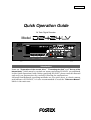
Introduction
Items on "Preparation of the current drive," "Formatting the disk" and "Set up of the
internal clock," which must be carried out upon purchasing D2424LV, are explained
in this Quick Operation Guide. Before operating D2424LV, please read this manual
and carry out preparations by carefully following the explanations.
Although fundamental operating methods are also given here, to obtain utmost
performance of D2424LV, it is also recommended to read the "Reference Manual"
which is the main text.
Model D2424LV Quick Operation Guide
2
Model D2424LV Quick Operation Guide
CAUTION:
CAUTION
TO PREVENT ELECTRIC SHOCK, MATCH WIDE BLADE OF
PLUG TO WIDE SLOT, FULLY INSERT.
RISK OF ELECTRIC SHOCK
DO NOT OPEN
ATTENTION:
POUR EVITER LES CHOCS ELECTRIQUES, INTRODUIRE
LA LAME LA PLUS LARGE DE LA FICHE DANS LA BORNE
CORRESPONDANTE DE LA PRISE ET POUSSER JUSQU'
AU FOND.
CAUTION: TO REDUCE THE RISK OF ELECTRIC SHOCK,
DO NOT REMOVE COVER (OR BACK).
NO USER - SERVICEABLE PARTS INSIDE.
REFER SERVICING TO QUALIFIED SERVICE PERSONNEL.
The lightning flash with arrowhead symbol, within an equilateral
triangle, is intended to alert the user to the presence of
uninsulated "dangerous voltage" within the product's enclosure
that may be of sufficient magnitude to constitute a risk of electric
shock to persons.
"WARNING"
The exclamation point within an equilateral triangle is intended
to alert the user to the presence of important operating and
maintenance (servicing) instructions in the literature
accompanying the appliance.
"TO REDUCE THE RISK OF FIRE OR ELECTRIC SHOCK,
DO NOT EXPOSE THIS APPLIANCE TO RAIN OR
MOISTURE."
SAFETY INSTRUCTIONS
10. Power Sources - The appliance should be connected to a
power supply only of the type described in the operating
1. Read Instructions - All the safety and operating instructions
instructions or as marked on the appliance.
11. Grounding or Polarization - The precautions that should be
should be read before the appliance is operated.
2. Retain Instructions - The safety and operating instructions
taken so that the grounding or polarization means of an
appliance is not defeated.
should be retained for future reference.
3. Heed Warnings - All warnings on the appliance and in the
12. Power Cord Protection - Power supply cords should be routed
so that they are not likely to be walked on or pinched by items
operating instructions should be adhered to.
4. Follow Instructions - All operating and use instructions should
placed upon or against them, paying particular attention to
cords at plugs, convenience receptacles, and the point where
be followed.
5. Water and Moisture - The appliance should not be used near
water - for example, near a bathtub, washbowl, kitchen sink,
they exit from the appliance.
13. Cleaning - The appliance should be cleaned only as
laundry tub, in a wet basement, or near a swimming pool, and
the like.
recommended by the manufacturer.
14. Nonuse Periods - The power cord of the appliance should be
6. Carts and Stands - The appliance should be used only with a
cart or stand that is recommended by the manufacturer.
unplugged from the outlet when left unused for a long period
of time.
15. Object and Liquid Entry - Care should be taken so that objects
do not fall and liquids are not spilled into the enclosure through
openings.
16. Damage Requiring Service - The appliance should be serviced
by qualified service personnel when:
A. The power supply cord or the plug has been damaged; or
B. Objects have fallen, or liquid has been spilled into the appliance;
or
C. The appliance has been exposed to rain; or
D. The appliance does not appear to operate normally or
exhibits a marked change in performance; or
E. The appliance has been dropped, or the enclosure damaged.
An appliance and cart combination should be moved with care.
Quick stops, excessive force, and uneven surfaces may cause
the appliance and cart combination to overturn.
7. Wall or Ceiling Mounting - The appliance should be mounted
to a wall or ceiling only as recommended by the manufacturer.
8. Ventilation - The appliance should be situated so that its location
17. Servicing - The user should not attempt to service the appliance
or position dose not interfere with its proper ventilation.
For example, the appliance should not be situated on a bed,
beyond that described in the operating instructions.
All other servicing should be referred to qualified service
sofa, rug, or similar surface that may block the ventilation
openings; or, placed in a built-in installation, such as a bookcase
personnel.
18. The appliance should be situated away from drops of water or
or cabinet that may impede the flow of air through the ventilation
openings.
spray of water.
19. Objects containing liquid such as vase must not be put on the
9. Heat - The appliance should be situated away from heat
sources such as radiators, heat registers, stoves, or other
appliance.
20. The appliance is not completely isolated from the power supply
appliances (including amplifiers) that produce heat.
even if the power switch is at off position.
3
Model D2424LV Quick Operation Guide
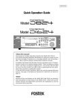
Contents
Package contents.............................................................................................................................5
Recording media..............................................................................................................................5
Preparation for the current drive....................................................................................................6
Installing a hard disk in the caddy...................................................................................................6
Formatting a hard disk drive...............................................................................................................9
Checking the available recording time (REMAIN) on a formatted disk......................................11
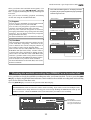
Setup of the Internal Clock............................................................................................................12
Connecting a analog mixer...........................................................................................................13
Connecting a digital mixer.............................................................................................................14
Initial settings....................................................................................................................................15
About Sampling Frequency.............................................................................................................15
Basic recording...............................................................................................................................16
Basic analog recording.......................................................................................................................16
Undo and redo recording (single undo/redo)...............................................................................17
Basic digital recording.......................................................................................................................18
Multitrack recording using overdubbing....................................................................................20
Ping-pong recording......................................................................................................................20
MIxdown.........................................................................................................................................................21
Basic Locate function....................................................................................................................21
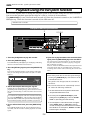
Recording in a new Program.........................................................................................................22
Changing the program FS.........................................................................................................23
Playback using the Vari-pitch function........................................................................................24
<Recording media>
The D2424LV is not equipped with recording media for recording and playback. Please read the section
from page 5 to prepare the recording media to record, playback, and edit data on the recorder.
<Damages>
Fostex in not responsible for any direct or consequential damages caused by operating the recorder and/
or a connected E-IDE hard disk.
<Copyrights>
It is prohibited by law to use materials recorded on the recorder from music CDs and/ or video tapes for
which copyrights belong to a third party for commercial contents, broadcasts, sales, and/ or distribution,
except for your personal entertainment.
4
Model D2424LV Quick Operation Guide
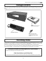
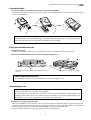
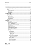
Package contents
Make sure that the package contains all the items listed below. The illustrations may not precisely
match the appearance of the actual items. If you find that items are missing, contact your local
dealer.
Main unit
Caddy
Install a hard disk into this case. Refer
to page “6” for more information.
Detachable controller
Hard disk fixing screws
Use these screws to fix the hard disk to
the caddy. Refer to page “7” for more
information.
Recording media
The D2424LV is not equipped with any recording medium for recording/playback such as a hard
disk drive (in this manual, we call the installed medium "current drive"). Therefore, to execute the
multitrack recording using the D2424LV, you have to separately prepare a current drive.
For a current drive, you can use any universal "E-IDE" hard disk drive* which has been tested and
approved by FOSTEX. A hard disk drive can be installed in the removable case attached.
<OPERATION CONFIRMED HD & BACKUP MEDIA LIST for FOSTEX D2424LV>
The updated information on the operation-confirmed HD and backup media for D2424LV is mentioned in the following Fostex international web site.
<http://www.fostex.co.jp/int/index.htm>
For those who are not able to check our web site, please contact Fostex distributor in your territory.
5
Model D2424LV Quick Operation Guide
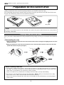
Preparation for the current drive
The D2424LV has a slot for an optional hard disk. First you need to install a hard disk into the
caddy included in this recorder package before you install it into the slot.
The following instructions assume that you have already purchased an E-IDE hard disk unit.
Prepare the following items for hard disk installation:
Hard disk unit
Fixing screws
Caddy
<Note>
Be sure to turn off the power to the D2424LV (or remove the power cable from the AC outlet) before
installing a hard disk.
Installing a hard disk in the caddy
First, you need to disassemble the caddy included in the package so that you can install a hard disk into
it.
• Disassembling the caddy
1.Apply your thumb to the edge of the case on the connector side as shown in the figure, and slightly pull the cover in the
direction of the arrow.
2.Apply your thumbs to the side of the case and open the cover. In the same manner, open the cover on the other side.
(Caution: Be careful not to pinch your fingers.)
<Notes on handling a hard disk>
• A hard disk is a high-precision device. Do not apply any impact to the disk when and after you install it in
the caddy. Do not leave the disk near a device that generates a strong magnetic field. Choose a level and
stable surface for installation. Be careful not to injure yourself.
Fostex is not liable for any malfunction or damage to the hard disk caused by mishandling.
• You need to set the DIP (Jumper) switch on the hard disk to “Master” before you install it into the caddy.
If the switch is set to “Slave,” the hard disk will not function correctly.
Refer to the instruction manual that came with your hard disk for more information on the DIP (Jumper)
switch setting.
6
Model D2424LV Quick Operation Guide
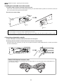
• Connecting cables
1.Connect the cables in the caddy to the connectors on the rear of the hard disk.
As shown in the figure, first connect the power supply cable. Make sure that you connect the cables securely
in the correct direction.
<Note on the connectors>
Some connectors on the hard disks may be too tight to connect cables easily. Do not apply excessive
force to such connectors to avoid injury or damage to the hard disk.
• Fixing the hard disk to the case
1.Align the screw holes.
As shown in the figure, align the screw holes on the side of the disk with the holes on the case.
2.Insert four included fixing screws (two screws on each side) and tighten them.
Align the screw holes on the other side of the hard disk with the holes
on the case.
Tighten four screws (two on each side).
<Note on tightening the screws>
Do not tighten the screws too much. Otherwise, you may damage the case.
• Assembling the case
<Note>
When you assemble the case, follow the note below:
If a projecting part on the hard disk touches the cover, apply the insulation seal (included in the
package) to the surface of the case where the part would touch. If you use the disk with its part
touching the cover, a short-circuit may occur, leading to a malfunction.
1.Assemble the case by installing the covers.
After you assemble the case, store the case in a place not subject to magnetic fields. If you remove the case
from the recorder and store or move the unit, cover the connectors on the caddy with the dust cover (included
in the package) to protect the hard disk from building up static electricity and dust.
Do not touch the connectors with your fingers to avoid static electricity.
7
Model D2424LV Quick Operation Guide
• Installing the removable case in the recorder
1. Install the caddy (containing a hard disk inside) into the slot.
Push in the case with the correct side facing toward you. (Use both hands to push it in so that the surface of
the case and the front panel become flush.)
2. Use the coin to lock the caddy.
Caddy
Coin etc.
<CAUTION>
Do not forget to lock the caddy installed into the slot.
When locking or unlocking the caddy with the coin, make sure that the recorder's power is off.
• Connecting a detachable controller
1. Attach a detachable controller (included) to the hooks on the front panel.
2. Securely insert the controller’s connector cable to the connector on the front panel.
Instead of using the controller, you may use an optional extension cable (Model 8551B). Consult your dealer
for more information.
Model 8551B Optional extension cable
Consult the dealer you purchased the recorder from or our sales office about information on
the extension cable.
8
Model D2424LV Quick Operation Guide
Formatting a hard disk drive
After installing a hard disk drive into the recorder, you must format the disk; otherwise you cannot
record or playback any data. Note that the following explanation assumes that the disk is
unformatted. If you want to know how to reformat a formatted disk, see the Reference manual.
<CAUTION>
Be sure to connect the recorder to the power supply specified in the specification section of the Reference manual. Do not use an AC outlet of any other voltage.
1. Turn the power on.
Flashing
The display will show the ROM version and time/date,
followed by “Initializing...” -> “Current IDE Drv” -> [(hard
disk model name)]. Then after “Unformat!” appears
momentarily, the recorder automatically accesses the
Disk Format menu in the SETUP mode and the following
screen appears.
SETUP
Flashing
SURE?
OL
0
3
6
9
12
18
24
30
42
∞
OL
0
3
6
9
12
18
24
30
42
∞
1
2
3
4
5
6
7
8
BIT
FS
kHz
CLOCK
9 10 11 12 13 14 15 16 17 18 19 20 21 22 23 24
Flashing
4. Select desired sampling frequency/quantization
with the Jog dial (or [PREV] key/[NEXT] key).
SETUP
OL
0
3
6
9
12
18
24
30
42
∞
OL
0
3
6
9
12
18
24
30
42
∞
1
2
3
4
5
6
7
8
BIT
FS
For sampling frequency/quantization, other settings
given in chart below can be selected in addition to the
presently shown "44.1kHz 24bit."
At selecting the sampling frequency/quantization, be
sure to refer to <Note> below.
kHz
CLOCK
9 10 11 12 13 14 15 16 17 18 19 20 21 22 23 24
2. Press the [EXECUTE/YES] key.
The E-IDE hard disk name will be displayed and, “SURE?”
and “?” will flash.
The sampling frequency and quantizing of the
current drive (E-IDE hard disk) are setup during the formatting or reformatting process.
Consequently, all programs in the current drive
will adhere to the sampling frequency used at
formatting. You can change the format, however, after compiling a program.
In other words, a variety of programs with different sampling frequencies can be installed on
the current drive. But alterable frequencies will
be limited, depending on quantization at formatting. For details, refer to page “23”.
Flashing
Flashing
SETUP
The sampling frequency:
SURE?
OL
0
3
6
9
12
18
24
30
42
∞
OL
0
3
6
9
12
18
24
30
42
∞
1
2
3
4
5
6
7
8
BIT
FS
kHz
CLOCK
9 10 11 12 13 14 15 16 17 18 19 20 21 22 23 24
3. Press the [EXECUTE/YES] key.
The display changes the screen for setting the sampling
frequency and quantization (default indication is “44.1
kHz 24bit?”).
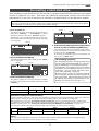
44.1kHz
Sampling frequency
Quantization
16 bits
24 bits
48kHz
24 bits
16 bits
24 real tracks + 32 additional tracks
Number of available tracks
88.2kHz
96kHz
24 bits
24 bits
8 real tracks + 48 additional tracks
<Available recording time after formatting>
A greater sampling frequency will reduce the available recording time/space after formatting. Under the same sampling frequency setting, the greater quantization (bit number) reduces the available recording time.
The following table shows the "approximate available recording time" under each sampling frequency/quantization.
Depending on your medium, the available recording time may differ slightly. It will be a good idea to check the
available recording time. See “Checking the available recording time (REMAIN) on a formatted disk” on page “11.”
Note that the available time values in the following table are based on a mono track recording.
Capacity
10.0GB
44.1kHz
48kHz
16 bits
24 bits
16 bits
Approx. 1888min.
Approx. 1258min.
Approx. 1735min.
24 bits
Approx. 1156min.
88.2kHz
96kHz
24 bits
24 bits
Approx. 628min. Approx. 577min.
<Note>
You cannot save audio data recorded in a 88.2kHz/24bit or 96kHz/24bit program using an adat digital signal.
See the Reference manual for details about the save/load operations.
9
Model D2424LV Quick Operation Guide
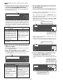
5. Select the desired sampling frequency using the
Jog dial and press the [EXECUTE/YES] key.
7. Press the [EXECUTE/YES] key while holding down
the [RECORD] button.
By pressing the [EXECUTE/YES] key after selecting the
sampling frequency, the screen for the multiple undo
On/Off setting will appear.
The size of unformatted area on the hard disk appears on
the display, and counts down as the formatting progresses.
It will take a while to complete formatting, especially if you
are formatting a large-capacity disk.
Flashing
SETUP
OL
0
3
6
9
12
18
24
30
42
∞
OL
0
3
6
9
12
18
24
30
42
∞
1
2
3
4
5
6
7
8
Upon completion of formatting, "COMPLETED!" will be
lit and the effective hard disk capacity as a result of
formatting will be indicated.
The display below is an example at formatting in "48kHz/
24 bit," and the number of effective tracks after formatting will be indicated as 24.
BIT
FS
kHz
CLOCK
9 10 11 12 13 14 15 16 17 18 19 20 21 22 23 24
In the initial setting, "On" will flash and if the Jog dial is
rotated in this state, either "On" or "Off" can be selected.
Normally, format is executed with multiple undo set to
"On" but if the current drive capacity is small and you
wish to limit consumption of the hard disk, it must be
set to "Off."
It is indicated as formatted in 48kHz/
24 bit.
Lit
SETUP COMPLETED!
OL
0
3
6
9
12
18
24
30
42
∞
Multiple Undo function
On (default)
Off
When set to On, the undo function is applied to all takes (recording, editing, etc.) executed
after the disk has been formatted. However, consumption of
the hard disk increases, so if the
disk capacity is not large
enough, we recommend setting
this function to Off.
When set to Off, the undo function is only applied to the current take (recording, editing,
etc.).
If the disk capacity is not large
enough, we recommend setting this function to Off.
OL
0
3
6
9
12
18
24
30
42
∞
1
2
3
4
5
6
7
8
6. Select “On” or “Off” via the Jog dial, and press the
[EXECUTE/YES] key.
It is indicated as formatted in 96kHz/
24 bit.
SETUP COMPLETED!
OL
0
3
6
9
12
18
24
30
42
∞
The screen for selecting the format appears (the default
shows “Standard Format?”).
You can select the format type between “Standard
Format” and “Quick Format” using the Jog dial.
To newly format the hard disk, select the initial setting
of "Standard format?" and proceed to the next step.
3
4
5
6
7
8
2
3
4
5
6
7
24
BIT
FS
kHz
CLOCK
INT
8
8. Press the [EXIT/NO] key or [STOP] button after
confirming that "COMPLETED!" is lit.
It will exit from the SETUP mode format menu and
change to indication of the head of disk (ABS 0) by ABS
time.
SETUP
2
OL
0
3
6
9
12
18
24
30
42
∞
1
Flashing
1
9 10 11 12 13 14 15 16 17 18 19 20 21 22 23 24
Display below is the example at completion of formatting in "96kHz/24 bit”.
Number of effective tracks after formatting is 8 (It will
also be 8 tracks when formatted in "88.2kHz/24 bit.").
Lit
OL
0
3
6
9
12
18
24
30
42
∞
FS
kHz
CLOCK
INT
The operating clock after
formatting is set to "Int."
For details on multiple undo function, refer to the Reference Manual.
OL
0
3
6
9
12
18
24
30
42
∞
24
BIT
BIT
FS
kHz
The program number is indicated. Immediately after formatting, one program is automatically made in the disk.
CLOCK
9 10 11 12 13 14 15 16 17 18 19 20 21 22 23 24
Format type
Standard Format (default)
Quick Format
During formatting, the recorder
checks the hard disk performance including the access
time of each block.
The time required for the format is longer but the reliability
is enhanced.
In general, it is best to select
this default format type.
Formatting this way, the recorder
assumes that all sectors in the
hard disk are good and simply
formats the disk.
The time required to format is very
short, however, bad sectors on
the disk will not be found.
Select this format type only when
using a new hard disk that is
checked by FOSTEX.
ABS
M
S
F
PGM
OL
0
3
6
9
12
18
24
30
42
∞
OL
0
3
6
9
12
18
24
30
42
∞
1
2
3
4
5
6
7
8
9 10 11 12 13 14 15 16 17 18 19 20 21 22 23 24
This indicates that the disk is located
at the head position (ABS 0).
10
BIT
24
FS
kHz
CLOCK
INT
Model D2424LV Quick Operation Guide
When you format the hard disk one Program (*1) is
automatically set up, and “ABS 00M 00S 00F” (ABS Time
Base - *2) appears, indicating that the top of the Program
is located.
Now, you can start recording, playback, and editing
on this unit using the installed hard disk.
• When ABS Time Base appears on the display, hold down
the [SHIFT] key and press the [DISP SEL] key repeatedly to
switch among these units.
ABS Time Base
ABS
(*1) Program:
M
S
F
PGM
OL
0
3
6
9
12
18
24
30
42
∞
You can set up a maximum of 99 Programs, limited
by the available space on your hard disk.
You can select any Program to perform recording,
playback, and edit (Program Select function).
You may also name the Programs to facilitate
managing individual songs (Program Title Edit
function). You can delete unnecessary Programs
(Program Delete function).
For more information, refer to the Reference Manual.
1
2
3
4
5
6
7
8
OL
0
3
6
9
12
18
24
30
42
∞
BIT
OL
0
3
6
9
12
18
24
30
42
∞
BIT
24
FS
kHz
CLOCK
INT
9 10 11 12 13 14 15 16 17 18 19 20 21 22 23 24
BAR/BEAT/CLK Time Base
BAR
OL
0
3
6
9
12
18
24
30
42
∞
1
2
3
4
5
6
7
8
PGM
24
FS
kHz
CLOCK
INT
9 10 11 12 13 14 15 16 17 18 19 20 21 22 23 24
(*2) Time Base:
This document and the Reference Manual use the
word “Time Base” frequently. This refers to the
units to indicate the current transport position of
the recorder, in other words, Absolute Time.
This recorder also uses MTC (MIDI time code) and
BAR/BEAT/CLK (bar/beat/clock). An MTC value is
a relative time value calculated by adding an MTC
offset value to the ABS time value. BAR/BEAT/CLK
indicates a position within a song of this recorder’s
tempo map based on the MIDI clock position pointer.
You can switch to any of these units as follows.
For more information on the Time Base, refer to the
Reference Manual.
MTC Time Base
MTC
H
M
S
F
PGM
OL
0
3
6
9
12
18
24
30
42
∞
OL
0
3
6
9
12
18
24
30
42
∞
1
2
3
4
5
6
7
8
BIT
24
FS
kHz
CLOCK
INT
9 10 11 12 13 14 15 16 17 18 19 20 21 22 23 24
Checking the available recording time (REMAIN) on a formatted disk
It is a good idea to check the available recording time after you format the disk. To do so, press the [DISP
SEL] key to display the REMAIN time indication, which indicates the available recording time and recording
space in the selected Time Base unit.
Press the [DISP SEL] key to return to the previous Time Base display.
<Note>
The REMAIN time values are based on a mono track recording. If you wish to record on multiple tracks,
you can find out how many minutes of a song you can record by dividing the REMAIN time value by the
number of tracks. Check the REMAIN value each time before you make a new recording.
Space remaining
REMAIN
H
M
S
OL
0
3
6
9
12
18
24
30
42
∞
OL
0
3
6
9
12
18
24
30
42
∞
1
2
3
4
5
6
7
8
9 10 11 12 13 14 15 16 17 18 19 20 21 22 23 24
11
BIT
24
FS
kHz
CLOCK
INT
Time remaining
When Bar/Beat/Clk is selected,
you can see the remaining recording space in bar/beat/click.
Model D2424LV Quick Operation Guide
Setup of the Internal Clock
This recorder contains an internal clock function.
Upon finishing format of the current drive, set internal clock to the present time by procedure
explained below. Procedures below is explained on the assumption that current drive has been
formatted, the program head (ABS 0) is displayed and this recorder is on standby.
<Note>
Be sure the internal clock is setup to the correct year, month, day and present time.
The year, month, day and time are important data necessary for executing the "Multiple Undo Function" explained in the Reference Manual. For details on multiple undo function, refer to the Reference Manual.
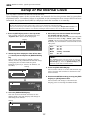
4. Move edit point with the Shuttle dial and input
the number with the Jog dial.
1. Press the [SETUP] key while in the stop mode.
The recorder will enter the SETUP mode and
“Signature Set?” menu will be displayed.
When the Shuttle dial is rotated CW, the edit point
will move in order of "day," "month," "year," "hour,"
"minute," but in reverse order when rotated CCW.
Numbers, etc. shown below can be entered at each
edit point.
Flashing
SETUP
OL
0
3
6
9
12
18
24
30
42
∞
OL
0
3
6
9
12
18
24
30
42
∞
1
2
3
4
5
6
7
8
BIT
24
FS
kHz
Hour
Minute
Day
Month
Year
CLOCK
INT
9 10 11 12 13 14 15 16 17 18 19 20 21 22 23 24
2. Rotate Jog dial to display the “Date & Time Set?”
(“?” flashes) menu and press the [EXECUTE/YES]
key.
<Note>
The "second" figures will start from 00 at the instant the following is executed (Pressing the [EXECUTE/YES] key). Press the [EXECUTE/YES] key in
reference to the time announcement.
The recorder will change to display of hour,
minute, second, day and month in real time setup
at shipping the recorder from the plant.
Example is January 8, 8 hour, 28 minutes, 54
seconds).
Flashing
5. Press the [EXECUTE/YES] key.
The recorder will be set to the time/month, day
that was input and continue to function as the
internal clock.
SETUP
OL
0
3
6
9
12
18
24
30
42
∞
OL
0
3
6
9
12
18
24
30
42
∞
1
2
3
4
5
6
7
8
BIT
24
FS
kHz
CLOCK
INT
9 10 11 12 13 14 15 16 17 18 19 20 21 22 23 24
6. Exit from the SETUP mode by pressing the [EXIT/
NO] key or [STOP] button twice.
The recorder will change to the time base
display prior to entering the SETUP mode.
SETUP
H
M
OL
0
3
6
9
12
18
24
30
42
∞
S
OL
0
3
6
9
12
18
24
30
42
∞
1
2
3
4
5
6
7
8
BIT
24
FS
kHz
CLOCK
INT
9 10 11 12 13 14 15 16 17 18 19 20 21 22 23 24
3. Press the [EXECUTE/YES] key.
The date section will flash and enter in the
editing mode. The time display will change to
indicating hour/minute.
Flashing
SETUP
H
M
OL
0
3
6
9
12
18
24
30
42
∞
OL
0
3
6
9
12
18
24
30
42
∞
1
2
3
4
5
6
7
8
:00 ~ 23
:00 ~ 59
:01 ~ 31
:January ~ December
:00 ~ 99
BIT
24
FS
kHz
CLOCK
INT
9 10 11 12 13 14 15 16 17 18 19 20 21 22 23 24
12
Model D2424LV Quick Operation Guide
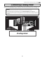
Connecting a analog mixer
The D2424LV is equipped with 24 [ANALOG INPUT] and 24 [ANALOG OUTPUT] connectors, allowing up to 24-channel input/output connection, which may be powerful for live recording, etc.
<Notes>
• At making connections with the mixer, switch off power to this unit and the mixer.
• Analog input/output ports of D2424LV are set to "unbalanced input/output" in the initial state.
These can be changed to "balanced input/output" by the "BAL (+4dBu)/UNBAL (-10dBV) setup menu" in
the SETUP mode in accordance to the application. For details on setup, refer to the separate "Reference
Manual."
Analog mixer
13
Model D2424LV Quick Operation Guide
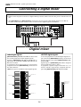
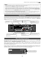
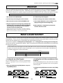
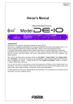
Connecting a digital mixer
When making connections with a digital recording mixer, refer to the connecting example below.
<CAUTION>
• When connecting the recorder to a digital mixing console, make sure that the power of both units are
off.
• The [DATA INPUT] and [DATA OUTPUT] connectors do not support adat digital signals of 96-kHz Fs.
In other words, the unit cannot receive of feed an adat digital signal of 96-kHz Fs.
Digital mixer
<adat digital signal>
<S/P DIF digital signal>
[DATA IN/OUTPUT] 1-8, 9-16 and 17-24 can all be used
for record/playback of adat digital signals.
Signals to [DATA INPUT] 1-8, 9-16 and 17-24 will, respectively, be assigned to tracks 1-8, 9-16 and 1724, and recorded.
At playback, the track outputs are respectively
assigned from each [DATA OUTPUT] connectors in
the same manner.
<Note>: Except for 96-kHz Fs adat digital signals.
At record/playback of S/P DIF digital signals, input connectors [DATA INPUT] 1-8 only can be used
and the output ports will be [DATA OUTPUT] 1-8, 916 and 17-24.
Signals input to [DATA INPUT] 1-8 will be assigned
and recorded in tracks 1 and 2.
At playback, signals output from track 1-2, 3-4
and 5-6 will be, respectively, assigned and output from [DATA OUTPUT] 1-8, 9-16 and 17-24.
TRK 24
TRK 24
TRK 23
TRK 23
TRK 22
TRK 22
TRK 21
DATA IN 17-24
TRK 21
DATA OUT 17-24
TRK 20
TRK 20
TRK 19
TRK 19
TRK 18
TRK 18
TRK 17
TRK 17
TRK 16
TRK 16
TRK 15
TRK 15
TRK 14
TRK 14
TRK 13
TRK 13
DATA IN 1-8
DATA OUT 9-16
DATA IN 9-16
TRK 12
TRK 12
TRK 11
TRK 11
TRK 10
TRK 10
TRK 9
TRK 9
TRK 8
TRK 8
TRK 7
TRK 7
TRK 6
TRK 6
TRK 5
TRK 5
TRK 4
DATA OUT 1-8
DATA IN 1-8
TRK 4
TRK 3
TRK 3
TRK 2
TRK 2
TRK 1
TRK 1
14
DATA OUT 17-24
DATA OUT 9-16
DATA OUT 1-8
Model D2424LV Quick Operation Guide
<Hints>
• When connecting the recorder to a digital mixing console as shown in the example above, unlike connecting to an
analog console, both digital devices must be synchronized with each other.
To achieve this, use "word clock," the signal for synchronization.
Word clock is used to synchronize all digital words in a system. Normally one digital devices in the system acts as
a master of word clock, and the other devices act as slaves. All the slave devices receive the word clock fed from the
master device and synchronize to it. In the example above, the recorder acts as a word clock master and the digital
mixing console acts as a slave and synchronizes with the recorder. The word clock is fed from the [WORD OUT PUT]
terminal of the recorder to the [WORD INPUT] terminal of the digital mixing console.
• Note that the master word clock setting of the digital mixing console must match the recorder's sampling frequency.
See the instruction manual of the digital mixing console for details.
To execute the digital multitrack recording using a digital mixing console, see "Basic digital recording" on page “16”
for details about the digital multitrack recording using a digital mixing console.
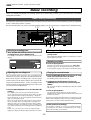
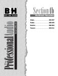
Initial settings
You need to reset all the controls on this recorder to their initial settings according to the controls and switches on
the mixer before you proceed to the next step. This procedure is called “Initialize” in this Guide and in the Reference
Manual. The buttons and switches on this recorder should be reset as shown below. Remember to “initialize this
recorder” before you start a new session.
Turn off AUTO PUNCH mode.
(The REHEARSAL and TAKE
LEDs go off.)
Turn off AUTO RTN mode and AUTO
PLAY mode. (AUTO RTN and AUTO
PLAY indicators turn off.)
Locate the top of the selected
Program (ABS 0).
AUTO RTN
AUTO RTN
CLIPBOARD
AUTO PLAY
The [STORE] key and [RECALL]
key LEDs turn off.
IN
AUTO PUNCH
START
OUT
IN
END
OUT
PGM SEL
EXIT/NO
EXECUTE/YES
24TRACK DIGITAL RECORDER
EJECT
PREVIEW
POWER
SHIFT
AUTO
PUNCH
24bit
96kHz
EDIT
SETUP
TC READY
TC GEN
REHEARSAL
UNDO/REDO
M.UNDO
LOCATE
CHARACTER
NEXT
PREV
PREV TC
NEXT TC
CHASE
LOCATE MEMORY
DISP SEL
STORE
TIME BASE SEL
HOLD
RECALL
VARI PITCH
TAKE
OPTICAL
RECORD
RECORD TRACK
1/9/17
2/10/18
3/11/19
4/12/20
5/13/21
P.EDIT
6/14/22
7/15/23
PLAY
STOP
REW
F FWD
TRACK SHIFT
8/16/24
FOOT SW
ENVELOPE
ACCESS
9-16
ALL READY
ALL INPUT
17-24
CLIPBOARD PLAY
LOCATE ABS 0
LOCATE REC END
TRACK SHIFT
Turn off the [TRACK SHIFT] key LED.
Stop the recorder. (The STOP
button LED turn off.)
Set all [RECORD TRACK] select keys to
“SAFE.” The track indicators (square
frames) turn off.
Turn off the Vari Pitch function. (The
[VARI PITCH] key LED turns off.)
About Sampling Frequency
The sampling frequency is important when recording a digital source, as described later in "Basic digital
recording", but is not as important when recording analog source.
As described earlier in "Formatting a hard disk drive", the sampling frequency and quantization of the current
drive (<44.1 kHz 16bit or 24bit>, <48 kHz 16bit or 24bit>, <88.2 kHz 24 bit> or <96 kHz 24bit>) are fixed
when formatting. Therefore, the sampling frequency of a digital device connected to the recorder must match
the recorder's sampling frequency.
In this recorder, the program to be complied in the current drive after formatting can be changed to any
sampling frequency. When several programs recorded using different sampling frequencies are in the current drive, sampling frequencies must be confirmed at each change of the program.
ABS
M
S
F
PGM
OL
0
3
6
9
12
18
24
30
42
∞
OL
0
3
6
9
12
18
24
30
42
∞
1
2
3
4
5
6
7
8
9 10 11 12 13 14 15 16 17 18 19 20 21 22 23 24
15
BIT
24
FS
kHz
CLOCK
INT
Sampling frequency and quantization.
Model D2424LV Quick Operation Guide
Basic recording
After you finish preparing a recording media and connecting a mixer, you can start basic recording
using this recorder.
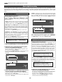
Basic analog recording
The following explanation assumes that this recorder has been connected to an external mixing console (as explained
in the “Connecting a Mixer” section).
Because the D2424LV can accept 24 channel analog signals, you can record up to 24 audio sources simultaneously.
4 6
1, 5
AUTO RTN
AUTO RTN
CLIPBOARD
AUTO PLAY
IN
AUTO PUNCH
START
OUT
IN
END
OUT
PGM SEL
EXIT/NO
DISP SEL
STORE
TIME BASE SEL
HOLD
EXECUTE/YES
24TRACK DIGITAL RECORDER
EJECT
PREVIEW
POWER
24bit
96kHz
EDIT
SETUP
SHIFT
TC READY
TC GEN
AUTO
PUNCH
REHEARSAL
UNDO/REDO
M.UNDO
LOCATE
CHARACTER
NEXT
PREV
PREV TC
NEXT TC
CHASE
LOCATE MEMORY
RECALL
VARI PITCH
TAKE
OPTICAL
P.EDIT
RECORD
RECORD TRACK
1/9/17
2/10/18
3/11/19
4/12/20
5/13/21
6/14/22
7/15/23
8/16/24
STOP
PLAY
REW
F FWD
TRACK SHIFT
FOOT SW
ACCESS
ALL READY
ALL INPUT
ENVELOPE
17-24
9-16
CLIPBOARD PLAY
LOCATE ABS 0
LOCATE REC END
TRACK SHIFT
2
3
7
Starting recording
Selecting a recording track
1. Press the [RECORD TRACK] select key of the desired
recording track to set it in READY mode.
3.Hold down the [RECORD] button and press the
[PLAY] button.
The “ready” track indicator (a small square) flashes on the
display.
The flashing RECORD LED and the track indicator (a small
square) light up steadily.
ABS
M
S
Stopping recording
F
PGM
OL
0
3
6
9
12
18
24
30
42
∞
OL
0
3
6
9
12
18
24
30
42
∞
1
2
3
4
5
6
7
8
BIT
24
FS
4.Press the [STOP] button.
kHz
CLOCK
INT
When the recorder section is stopped, the “Please Wait!”
message appears on the display momentarily, then the
current position appears. The ready track indicators flash.
9 10 11 12 13 14 15 16 17 18 19 20 21 22 23 24
Flashing
Adjusting the recording level
Playing the recorded tracks
5.Press the [RECORD TRACK] select keys for the ready
tracks to set the tracks in the safe status.
This recorder does not have any recording level
controls. You need to adjust the recording level on the
device that outputs recording data. Use the group
master faders on the mixer (faders that control the
output level of BUSS OUTs). Set the recording tracks
on this recorder to input monitoring status so that you
can check the level adjustment.
The flashing track indicators turn off.
6. Hold down the [STOP] button and press the
[REWIND] button to locate the top of the Program
(ABS 0).
The top of the Program is immediately located in LOCATE
ABS 0 mode.
2.Press the [RECORD] button once. (The RECORD LED
flashes.)
7.Press the [PLAY] button.
The playback starts from the top of the Program.
Adjust the level of input signal at TAPE IN on the mixer and
monitor the sound.
The “ready” tracks enter the input monitoring status.
As you raise the group output level on the mixer, the level
meter segments of the ready tracks light up. Adjust the
level so that the “0” to “3” level segments of the level meter
light up at the highest peak.
If the “OL” segments of the meter light up, the recording
level is too high. If the recording level is too high on a
digital recorder, the recording signal may distort, unlike
an analog recorder. Especially, if you are recording vocal
or acoustic instruments, the recording level may suddenly
peak.
In this case, you may want to lower the signal peak by
applying a compressor/limiter using an insertion connector.
Repeat the procedure described above to record more tracks
(mono track or multiple tracks). You can record eight different
sound sources on this recorder simultaneously.
<Undo and redo recording>
If you make a mistake or you are not satisfied with the
recording, you can “undo” recording. Refer to the “Undo
and redo recording” section below.
16
Model D2424LV Quick Operation Guide
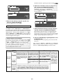
Undo and redo recording (single undo/redo)
Everybody makes mistakes. If you make a mistake in recording, you can restore and re-do the data that
existed before the mistake occurred. These functions are called “Undo” and “Redo,” and are executed by
the [UNDO/REDO] key on the control panel.
The Undo function enables you to cancel the latest recording or edit and restore the previous state.
Using the Redo function after using the Undo function enables you to cancel the Uno operation and
restore the latest recording or edit. These functions have some limitations as described in the <Note>
below.
As described earlier in "Formatting a new disk", if you format the disk with the multiple undo function ON, "multiple undo" is possible. See "Multiple undo function" in the Reference manual.
<Note>
After recording
You can repeatedly use the Undo/Redo functions until you
perform one of the following operations:
Recorded area
Undo
• You make a new recording.
• You perform a new edit (Copy/Paste, Move/Paste, Auto
Punch in/out, Erase, etc.).
• You turn off the power to the recorder.
• You select a different Program.
• You execute the Multiple Undo operation.
Redo
Before recording
Performing the Redo operation will cancel the Undo
operation and restore the state obtained after recording.
AUTO RTN
AUTO RTN
CLIPBOARD
AUTO PLAY
IN
AUTO PUNCH
START
OUT
IN
END
OUT
PGM SEL
EXIT/NO
DISP SEL
STORE
TIME BASE SEL
HOLD
EJECT
PREVIEW
SHIFT
AUTO
PUNCH
EDIT
SETUP
TC READY
TC GEN
UNDO/REDO
M.UNDO
REHEARSAL
LOCATE
CHARACTER
NEXT
PREV
PREV TC
NEXT TC
SETUP
EXECUTE/YES
OL
0
3
6
9
12
18
24
30
42
∞
CHASE
LOCATE MEMORY
RECALL
VARI PITCH
OL
0
3
6
9
12
18
24
30
42
∞
1
2
3
4
5
6
7
8
BIT 16 20 24 32
FS
kHz
CLOCK
INT
9 10 11 12 13 14 15 16 17 18 19 20 21 22 23 24
TAKE
P.EDIT
RECORD
PLAY
STOP
REW
F FWD
<Hints>
ALL READY
CLIPBOARD PLAY
LOCATE ABS 0
LOCATE REC END
The single undo/redo function executes undo/
redo operation only against the latest take.
The "multiple undo function" can execute undo
against all takes after the current disk had been
formatted. When the multiple undo function is
set to ON, the recorder stores all takes automatically and can recall the desired take (undo) if
necessary.
1, 2 ([UNDO/REDO] key)
1.After making a recording (or playing back a newly
recorded data), press the [UNDO/REDO] key.
The recorder displays “Undo!”, then “COMPLETED !”, and
displays the previous Time Base indication.
Undoing the recording will restore the status obtained
before recording.
<Cautions for the multiple undo function>
• Multiple undo is possible only when the current
disk is formatted with the "Multiple undo
function" ON.
• A disk formatted with the multiple undo function
ON has more information stored on it more than
a disk formatted with the multiple undo function
OFF.
SETUP
OL
0
3
6
9
12
18
24
30
42
∞
OL
0
3
6
9
12
18
24
30
42
∞
1
2
3
4
5
6
7
8
BIT 16 20 24 32
FS
kHz
CLOCK
INT
• With the single undo/redo function described
above, the data you undo will be erased when the
next recording is done. Therefore, once you
execute a single undo, the undone take cannot be
restored even if you execute multiple undo later.
9 10 11 12 13 14 15 16 17 18 19 20 21 22 23 24
2.To cancel the undo operation, press the [UNDO/
REDO] key again.
The recorder displays “Redo!”, then “COMPLETED !”, and
displays the previous Time Base indication.
* Refer to the Reference manual for details.
17
Model D2424LV Quick Operation Guide
Basic digital recording
In the following, basic multi-recording of adat digital signals will be carried out on the assumption that a
digital mixer is connected to D2424LV (To output adat digital signals from the digital mixer, refer to the
Operating Manual of the digital mixer you are using). Prior to operation, D2424LV must be set to the “Initial
state.”
"DIGITAL" will be lit if set to the asynchronous mode while
a correct adat digital signal is being input from the digital
mixer, and "EXT" will also be lit if set to the synchronous
mode. If it is locked to the word signal, "WORD" will be lit.
Selecting Digital In
<About Digital In selection>
For setup items of digital in, in addition to the initial
setting of "Analog," "SPDIF: Async," "SPDIF: Sync," "adat:
Async" or "adat: Sync" can be selected and setup to match
the application.
Flashing
SETUP
OL
0
3
6
9
12
18
24
30
42
∞
"Analog" indicates that none of the tracks are assigned
to digital in and is the setting in which digital signals
cannot be input to any of the [DATA INPUT] connectors.
1
"SPDIF:Async" and "SPDIF: Sync" are used when assigning S/P DIF signals (L, R) from external digital equipment to tracks 1 and 2 of D2424LV, and selected to
digital in asynchronous (Async) or synchronous (Sync)
depending on the system in
use. In this case, [DATA INPUT] 1-8 only can be used.
1
4
5
6
7
8
FS
2
3
4
5
6
7
8
3
4
5
6
7
8
9 10 11 12 13 14 15 16 17 18 19 20 21 22 23 24
FS
kHz
EXT
WORD
DIGITAL
[DATA OUTPUT] 1-8: Outputs of tracks 1 - 2
[DATA OUTPUT] 9-16: Outputs of tracks 3 - 4
[DATA OUTPUT] 17-24: Outputs of tracks 5 - 6
SETUP
1
2
24
CLOCK
When set to "D.out SPDIF," outputs of two tracks (1-2,
3-4, 5-6) will be assigned to digital out. It will thus be
possible to ouput S/P DIF signals (L, R) to external digital equipments. Signals listed below will be output from
each [DATA OUTPUT] connectors.
kHz
CLOCK
BIT
BIT
24
Flashing
OL
0
3
6
9
12
18
24
30
42
∞
OL
0
3
6
9
12
18
24
30
42
∞
9 10 11 12 13 14 15 16 17 18 19 20 21 22 23 24
[DATA OUTPUT] 1-8: Outputs of tracks 1 - 8
[DATA OUTPUT] 9-16: Ouputs of tracks 9 - 16
[DATA OUTPUT] 17-24: Outputs of tracks 17 - 24
9 10 11 12 13 14 15 16 17 18 19 20 21 22 23 24
OL
0
3
6
9
12
18
24
30
42
∞
8
In addition to the initial setting of "D.out adat" from
among the digital out setup items, "D.out SPDIF" can
also be selected, and setup in compliance with the application. When set to "D.out adat," outputs of tracks 1
-8 (6-16, 17-24) will be assigned to digital out. This will
be the initial setting and signals can be output to digital mixers and adat equipments provided with adat input functions. The following signals will be output from
each [DATA OUTPUT] connectors.
SETUP
3
7
<About Digital Out selection>
The current selection will be displayed together with
"D. in?" (the default is "Analog").
By pressing the [EXECUTE/YES] key, the selection starts
flashing, showing that you can now change the
selection.
2
6
FS
kHz
CLOCK
Selecting Digital Out
2. Select the “D. in?” menu by using the Jog dial,
and press the [EXECUTE/YES] key.
1
5
24
After completing the Digital In setting, select "Digital Out".
When setting Digital In to an "Async" mode (“adat: Async”
or “SPDIF: Async”), Also select "Reference clock".
1. Press the [SETUP] key to enter the SETUP mode.
BIT
4
OL
0
3
6
9
12
18
24
30
42
∞
[DATA INPUT] 1-8: Tracks 1 - 8 will be assigned.
[DATA INPUT] 9-16: Tracks 9 - 16 will be assigned.
[DATA INPUT] 17-24: Tracks 17 - 24 will be assigned.
OL
0
3
6
9
12
18
24
30
42
∞
3
BIT
SETUP
"adat:Async" and "adat: Sync" are used to assign adat
signals (ch 1-ch 8) from external digital equipments to
tracks 1-8 (9-16, 17-24) of D2424LV, and in compliance to the system, select it to asynchronous (Async)
or synchronous (Sync) with digital-in.
In this case, all [DATA INPUT] connctors can be used and
each input port will function as shown below.
OL
0
3
6
9
12
18
24
30
42
∞
2
OL
0
3
6
9
12
18
24
30
42
∞
24
FS
kHz
CLOCK
9 10 11 12 13 14 15 16 17 18 19 20 21 22 23 24
4. Select the “D.out?” menu by using the Jog dial,
and press the [EXECUTE/YES] key.
3. Select “adat: Async” or “adat: Sync” by using the
Jog dial, and press the [EXECUTE/YES] key.
The current selection is displayed together with "D. out?".
The default is “D.out adat”. If another selection is
displayed,select “D.out adat” using the following
operation. Press the [EXECUTE/YES] key and the
current selection will starts flashing.
To lock the mixing console to recorder's WORD OUT (or
digital out), select “adat: Async”.
If the mixing console cannot be locked to the digital word
clock, select “adat: Sync”.
18
Model D2424LV Quick Operation Guide
6. Select the “Clock Sel?” menu via using the Jog
dial, and press the [EXECUTE/YES] key.
SETUP
OL
0
3
6
9
12
18
24
30
42
∞
OL
0
3
6
9
12
18
24
30
42
∞
1
2
3
4
5
6
7
8
BIT
24
The current reference clock is displayed together with
"Clock Sel?". The default is “Clock Sel Int”.
Press the [EXECUTE/YES] key, and the current selection
will start flashing.
FS
kHz
CLOCK
9 10 11 12 13 14 15 16 17 18 19 20 21 22 23 24
Flashing
SETUP
SETUP
OL
0
3
6
9
12
18
24
30
42
∞
OL
0
3
6
9
12
18
24
30
42
∞
1
2
3
4
5
6
7
8
BIT
OL
0
3
6
9
12
18
24
30
42
∞
24
FS
kHz
CLOCK
1
2
3
4
5
6
7
8
OL
0
3
6
9
12
18
24
30
42
∞
BIT
OL
0
3
6
9
12
18
24
30
42
∞
BIT
24
FS
kHz
CLOCK
9 10 11 12 13 14 15 16 17 18 19 20 21 22 23 24
9 10 11 12 13 14 15 16 17 18 19 20 21 22 23 24
Flashing
5. Select “D.out adat” by using the Jog dial, and
press the [EXECUTE/YES] key.
SETUP
OL
0
3
6
9
12
18
24
30
42
∞
Now the Digital Out is set to "adat".
Setting the reference clock
1
When setting "Digital In" (see the previous page) to
an "Async" mode ("adat: Async" or "SPDIF: Async"),
you must select whether the recorder is referenced
to the internal clock or word clock from an external
digital device. When setting "Digital In" to a "Sync"
mode ("adat: Sync" or "SPDIF: Sync"), the recorder is
referenced to the word clock received through the
external digital audio signal.
Int
Regardless of receiving or not
receiving word clock from
clock received WORD IN, the recorder is reffrom WORD IN erenced to the internal clock.
When the recorder receives
SPDIF :Async
correct digital signals, the
“DIGITAL” indicator lights in
adat :Async
the display.
no clock
received from
WORD IN
clock received
from WORD IN
SPDIF :Sync
adat :Sync
no clock
received from
WORD IN
4
5
6
7
8
9 10 11 12 13 14 15 16 17 18 19 20 21 22 23 24
The reference clock is now set to your desired clock.
When connecting the recorder to a digital mixing
console that can accept the word clock from the WORD
OUT of the recorder, set the recorder's reference clock
to “Int”. See the table below in other cases.
8. Press the [EXIT/NO] key or [STOP] button to exit
the SETUP mode.
You must set the reference clock when setting "Digital
In" (see the previous page) to an "Async" mode ("adat:
Async" or "SPDIF: Async"). You can select from “Auto”,
“Word” and “Video” in addition to the default “Int”.
Note that “Video” is available only when the optional
TC/SYNC card (model 8346) is installed.
See the table below about the relation between the Digital In setting and reference clock.
[Clock Sel ?]
setting
3
FS
kHz
CLOCK
7. Select the desired reference clock by using the
Jog dial, and press the [EXECUTE/YES] key.
<About reference clock setting>
[D. in ?] setting
2
24
The display shows the beginning of the disk with ABS
time base.
After complete “Digital In”, “Digital Out” and “Reference
Clock” settings, execute the basic recording in a similar
manner to "Basic analog recording" described earlier.
Auto
When receiving word clock
from WORD IN, the recorder
automatically synchronizes to
the incoming clock, while the
“ D I G I TA L ” , “ E X T ” , a n d
“WORD” indicators light in the
display.
When no word clock is received, the recorder is referenced to the internal clock,
while the “EXT” indicator
flashes.
Word
When receiving word clock
from WORD IN, the recorder
synchronizes to the incoming
clock, while the “DIGITAL”,
“EXT”, and “WORD” indicators
light in the display.
Available only
when installing
the optional
Model 8346 TC/
SYNC card. If you
try to select
“Video,” “Void w/
When no word clock is re- o 8346” is disceived, the “EXT” indicator played and you
flashes showing that the re- cannot select it.
See the appendix
corder cannot be locked.
of the Reference
manual for details.
Regardless of receiving or not receiving word clock from WORD IN, the recorder synchronizes to the external S/P DIF digital signal. When the recorder receives correct digital
signals, the “DIGITAL” and “EXT” indicators light in the display. When Digital In is set to a
SYNC mode, if you try to select “Clock Sel?” menu, The display will show “Clock Sel
D.in!” (indicating that the clock is set to Digital In!) and the recorder ignores your operation.
19
Video
Model D2424LV Quick Operation Guide
Multitrack recording using overdubbing
Multitrack recording is a term for the series of processes in which you record various sound sources to
different tracks and combine them into two mixes (L and R). This recording involves an important
process called “overdubbing,” in which you record additional sound sources to different tracks while
monitoring the input sound and listening to the recorded sound. The following procedure assumes that
you have already recorded a rhythm section using a drum machine on Track 1.
Initialize the recorder.
1. Press the [RECORD TRACK] select key of the desired
overdubbing track to set it in READY mode.
5. Press and hold down the [RECORD] button and
press the [PLAY] button. (Take)
The “ready” track’s indicator (a small square) flashes on
the display.
Play the sound source accompanying the Track 1 sound in
the same way as during the rehearsal.
2. Press the [RECORD] button once.
6. When you finish overdubbing, stop this unit, locate
the top of the Program, and play the overdubbed
sound as explained in the “Basic Recording And
Playback.”
The ready tracks enter input monitoring status, and the
other tracks enter playback monitoring status.
3. Press the [PLAY] button to play the Program from
the beginning. (Rehearsal)
If you are not satisfied with your overdubbing, perform
the Undo function and record again.
Adjust the level of the playback monitoring sound (rhythm
sound on Track 1) on the mixer. Play the sound source to
overdub and adjust the recording level on the mixer.
In the same way, overdub the necessary tracks.
4. When you finish rehearsing, locate the top of the
Program for the actual take.
Ping-pong recording
Ping-pong recording is a recording process in which you mix the playback sound of multiple tracks and
record the mix on an empty track. Ping-pong recording enables you to use previously-recorded tracks in
a new recording. In this way, you can overdub more sound sources using a limited number of tracks.
The following procedure explains how to ping-pong record the sound sources recorded on Tracks 1-6 to
Tracks 7 and 8. Once you ping-pong record the tracks, you cannot apply effects to the individual tracks.
If necessary, apply effects on the mixer prior to ping-pong recording.
Initialize the recorder.
1. Set all tracks to the SAFE status.
6. Start recording on the master recorder. (Take)
2. Locate the top of the Program on this recorder.
7. Press the [PLAY] button on this recorder to start
playing the Program from the beginning.
3. Set the master recorder to REC-STANDBY mode.
8. When mixdown is completed, stop the master
recorder and this recorder.
4. Play the Program from the beginning and adjust
the recording level on the master recorder while
adjusting the tonal quality and mix balance of the
playback sound from the mixer. (Rehearsal)
Adjust the input level on the master recorder so that the
STEREO OUT L/R meters on the mixer respond to the same
degree as the level meters on the master recorder.
5. Locate the top of the Program.
20
Model D2424LV Quick Operation Guide
Mixdown
After overdubbing and ping-pong recording, you can mix all track data into two channel stereo data and
record it onto your master recorder. This final process of multitrack recording is called “mixdown.”
The mixdown signals are usually output from the mixer’s STEREO OUT L/R. Connect the master recorder
Initialize the recorder.
1. Set all tracks to the SAFE status.
5. Locate the top of the Program.
2. Locate the top of the Program on this recorder.
6. Start recording on the master recorder. (Take)
3. Set the master recorder to REC-STANDBY mode.
7. Press the [PLAY] button on this recorder to start
playing the Program from the beginning.
4. Play the Program from the beginning and adjust the
recording level on the master recorder while adjusting
the tonal quality and mix balance of the playback
sound from the mixer. (Rehearsal)
8. When mixdown is completed, stop the master
recorder and this recorder.
Adjust the input level on the master recorder so that the
STEREO OUT L/R meters on the mixer respond to the same
degree as the level meters on the master recorder.
Basic Locate function
The Locate function enables you to locate the desired point (move the current position of the recorder)
immediately. There are two locate methods: storing the desired locate point (time or bar/beat/clock
value) into the memory keys, and locating the point without storing it.
This section explains “Locating the top of the Program” and “Locating the last recording point in the Program”
and do not involve storing locate points. Refer to the Reference Manual for information on storing and
locating locate points.
On this recorder, the top of the Program on the disk is called “ABS 0” and the end of the recorded area is called “REC END.” (If the
Program has no data recorded, ABS 0 corresponds to REC END.) You can use this function to locate the ABS 0 or REC END point
immediately, regardless of the current recorder position.
ABS 0
REC END
Recorded Area
LOSATE REC END
LOCATE ABS 0
Current Position
• Locating the end of the recorded area of the
Program
• Locating the top of the Program
You can immediately move to the top of the Program
(ABS 0), regardless of the current position of the
Program.
You can immediately move to the end of the recorded
area of the Program, regardless of the current position
of the Program.
1.Press and hold down the [STOP] button, and press
the [REWIND] button.
1.Hold down the [STOP] button and press the [F FWD]
button.
21
Model D2424LV Quick Operation Guide
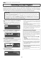
Recording in a new Program
The explanation so far has been based on one Program set up when you format a current drive (E-IDE
hard disk or SCSI disk). You may create up to 99 Programs, depending on the available disk space.
Multiple Programs do not interfere with each other. You can record, play, and edit each Program
independently, which facilitates song management. This section explains how to set up a new Program
on the disk. Refer to the reference manual for more information regarding Programs.
<CAUTION>
• When creating a new program, the initial settings such as the tempo map are copied from the current
program. For example, if the default tempo map is edited in the current program, the edited tempo map is
copied to the newly created program.
• A new compilation is possible only when the “Chain Play?” (Setup of the chain play mode) menu in the
SETUP mode is set to “Off.” If the [PGM SEL] key is pressed when the “Chain Play?” menu is set in other than
the “Off” mode, the recorder will enter the “Chain Play mode”. Before starting compilation, check that the
“Chain Play?” is “Off” and if it is not, be sure to reset it to “Off.”
1. While this recorder is stopped, press the [PGM SEL]
key.
Normally, any new program that is compiled will be
in the sampling frequency set when formatting the
current drive.
However, in this recorder, it is possible to change the
program sampling frequency.
In other words, programs with different sampling
frequencies can be made in the current drive and
thus recordingd can be matched to a chosen task.
For details refer to the next page.
The display indicates “Select PGM!” momentarily, then
shows the title of Program 1. The Program number and
“SURE?” flash.
SURE?
PGM
OL
0
3
6
9
12
18
24
30
42
∞
OL
0
3
6
9
12
18
24
30
42
∞
1
2
3
4
5
6
7
8
24
BIT
FS
kHz
CLOCK
INT
9 10 11 12 13 14 15 16 17 18 19 20 21 22 23 24
2.Turn the Jog dial clockwise to select “New Program?”.
<Selecting the desired Program>
The “?” mark of “New Program?”, and “SURE?” flash,
indicating that you can set up a new Program.
If you have set up multiple Programs on the disk,
you first need to select the target Program prior to
recording, playback, or edit. To select a Program,
follow the steps below. Do not select a different
Program until you finish the session.
SURE?
PGM
OL
0
3
6
9
12
18
24
30
42
∞
OL
0
3
6
9
12
18
24
30
42
∞
1
2
4
3
5
6
7
8
24
BIT
FS
kHz
CLOCK
INT
9 10 11 12 13 14 15 16 17 18 19 20 21 22 23 24
1.While this recorder is stopped, press the [PGM
SEL] key.
3. Press the [EXECUTE/YES] key.
“Select PGM!” appears momentarily, then the
number and title of the current Program appear.
This recorder sets up a new Program (Program 2) and enters
the “Title Edit?” menu in SETUP mode, showing the following
display. In this example, we use the default title.
You can change the title later. Refer to the Reference manual
for more information.
2.Turn the Jog dial clockwise or counter-clockwise.
The numbers and titles of the Programs on the
disk appear in turn.
SETUP
OL
0
3
6
9
12
18
24
30
42
∞
OL
0
3
6
9
12
18
24
30
42
∞
1
2
3
4
5
6
7
8
24
BIT
FS
3.Select the desired Program number and press the
[EXECUTE/YES] key.
kHz
CLOCK
INT
9 10 11 12 13 14 15 16 17 18 19 20 21 22 23 24
The top of the selected Program appears in ABS
Time Base (ABS 0).
4. Press the [EXIT/NO] key.
This recorder exits SETUP mode, and the top of Program 2
in ABS Time Base (ABS 0) appears.
ABS
H
M
S
F
PGM
OL
0
3
6
9
12
18
24
30
42
∞
OL
0
3
6
9
12
18
24
30
42
∞
1
2
3
4
5
6
7
8
BIT
24
FS
kHz
CLOCK
INT
9 10 11 12 13 14 15 16 17 18 19 20 21 22 23 24
22
Model D2424LV Quick Operation Guide
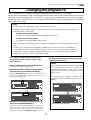
Changing the program FS
In the following, we will change a program’s sampling frequency in the current drive.
IN general, tha sampling frequency of the program made in the current drive will be the value set during
the most recent formatting of the current drive. But even after a program has been made, the sampling
frequency can be changed. However, the changes will be limited as follows depending on the quantizing
figure when formatting.
<Note>
• Do not change the sampling ferquency of a completed program.
• Changing of the sampling frequency will be limited by the quantizing figure (16bit or 24bit) set at
formatting of the current drive.
Current drive formatting by 24bit:
A program in 44.1kHz, 48kHz, 88.2kHz or 96kHz can be made.
Current drive formatting by 16bit:
A program in 44.1kHz or 48kHz can be made.
• Please remember the following points should there be programs with a different FS in the current
drive.
* Do not copy or paste between programs with different FS. Fostex cannot take responsibility in
compensation of data which had been “copied” or “pasted” between programs with different FS.
* In the section “Digital recording” explained above, be sure to set the external digital equipment
sampling frequency the same as that of the program.
1. First, start the program in which the FS is to be
changed by using the “program change” menu
explained above.
5.Exit from the SETUP mode by pressing the [EXIT/
NO] key or [STOP] button.
<Note>
2. Press the [SETUP] key to enter the SETUP mode.
If you change the FS (44.1 or 48kHz) of a program
in the 24-track mode to 88.2 or 96kHz, the
program automatically changes to the 8-track
mode and track numbers 1 through 8 on the
display are lit.
The display will change to SETUP mode.
3. Rotate the Jog dial to display the “Sample Rate?”
menu and then press the [EXECUTE/YES] key.
When the [EXECUTE/YES] key is pressed, the FS figure of
the current activated program will flash and the recorder
will enter the editing mode.
The following shows display examples when
changing the FS of a 48kHz/24bit program to
96kHz.
Flashing
SETUP
OL
0
3
6
9
12
18
24
30
42
∞
OL
0
3
6
9
12
18
24
30
42
∞
1
2
3
4
5
6
7
8
BIT
24
FS
ABS
kHz
M
S
F
CLOCK
INT
PGM
OL
0
3
6
9
12
18
24
30
42
∞
OL
0
3
6
9
12
18
24
30
42
∞
9 10 11 12 13 14 15 16 17 18 19 20 21 22 23 24
1
2
3
4
5
6
7
8
24
BIT
FS
kHz
CLOCK
INT
9 10 11 12 13 14 15 16 17 18 19 20 21 22 23 24
Flashing
SETUP
OL
0
3
6
9
12
18
24
30
42
∞
OL
0
3
6
9
12
18
24
30
42
∞
1
2
3
4
5
6
7
8
BIT
24
ABS
M
FS
S
F
kHz
PGM
CLOCK
INT
OL
0
3
6
9
12
18
24
30
42
∞
OL
0
3
6
9
12
18
24
30
42
∞
9 10 11 12 13 14 15 16 17 18 19 20 21 22 23 24
1
4. Display the desired FS by rotating the Jog dial, an
then press the [EXECUTE/YES] key.
2
3
4
5
6
7
8
Track numbers 1 through 8 are lit.
Either “44.1” or “48” can be selected in the 16bit current
drive, “44.1,” “48,” “88.2,” or “96” can be selected in the
24 bit current drive. After selection, the recorder will be
set to the chosen FS when the [EXECUTE/YES] key is pressed.
23
BIT
24
FS
kHz
CLOCK
INT
Model D2424LV Quick Operation Guide
Playback using the Vari-pitch function
This section explains how to change the playback speed of the recorder using the Vari Pitch function.
You can set the playback speed in the range of +6.0% to -6.0% in 0.1% increments.
The [VARI PITCH] key turns Vari Pitch mode on and off. When the function is turned on, the VARI PITCH
LED lights up. When the function is turned off, the LED turns off.
Initialize the recorder.
Vari-pitch function procedures
3
2,3,5,6
AUTO RTN
AUTO RTN
CLIPBOARD
AUTO PLAY
IN
AUTO PUNCH
START
OUT
IN
END
OUT
PGM SEL
EXIT/NO
EXECUTE/YES
24TRACK DIGITAL RECORDER
EJECT
PREVIEW
POWER
SHIFT
24bit
96kHz
AUTO
PUNCH
EDIT
SETUP
TC READY
TC GEN
REHEARSAL
UNDO/REDO
M.UNDO
LOCATE
CHARACTER
NEXT
PREV
PREV TC
NEXT TC
CHASE
LOCATE MEMORY
DISP SEL
STORE
TIME BASE SEL
HOLD
RECALL
VARI PITCH
TAKE
OPTICAL
2/10/18
3/11/19
4/12/20
5/13/21
P.EDIT
RECORD
RECORD TRACK
1/9/17
6/14/22
7/15/23
8/16/24
STOP
PLAY
TRACK SHIFT
FOOT SW
ALL INPUT
ENVELOPE
ACCESS
17-24
9-16
TRACK SHIFT
REW
F FWD
4
ALL READY
CLIPBOARD PLAY
LOCATE ABS 0
LOCATE REC END
1
1. Press the [PLAY] button to play this recorder.
6. If you wish to play back data at the current Vari Pitch
again, press the [VARI PITCH] key to turn the LED on.
2. Press the [VARI PITCH] key.
You can turn the Vari Pitch function on and off and edit
the pitch data while this recorder is playing or stopped,
but not during recording.
However, if the Vari Pitch function has already been turned
on and the pitch data was specified before you started
recording, this recorder will record using the current Vari
Pitch.
The VARI PITCH key LED lights up on the display, indicating
that the Vari Pitch function is turned on.
3. Press the [RECALL] key, then press the [VARI PITCH]
key.
The current pitch data flashes on the display, indicating
that you can change the pitch data now. (The “%” mark
flashes.)
OL
0
3
6
9
12
18
24
30
42
∞
OL
0
3
6
9
12
18
24
30
42
∞
1
2
3
4
5
6
7
8
BIT
<Notes>
• Even if the pitch data is 0.0% (no speed change),
pressing the [VARI PITCH] key will still turn on the
VARI PITCH function.
The speed is not changed, but the Vari Pitch is
turned on.
24
FS
kHz
CLOCK
INT
9 10 11 12 13 14 15 16 17 18 19 20 21 22 23 24
• The Vari Pitch function is automatically turned
off under the following conditions:
4. Set the desired pitch data using the Jog dial.
Rotating the Jog dial enables you to hear changes in
playback speed. Rotating the Jog dial clockwise increases
the speed, and rotating it counter-clockwise decreases the
speed.
1. You have turned off and on the power to this recorder.
The pitch data will be reset to 0.0%.
To continue the playback with the Vari Pitch function
on, press the [EXIT/NO] key. This recorder exits Vari Pitch
data edit mode, indicates the previous Time Base display,
and continues playing with the Vari Pitch you just set.
2. You must press the [EXECUTE/YES] key while
holding down the [SHIFT] key to turn the "SLAVE
mode" on (the setting pitch data remains).
3. You set "Digital In" of the SETUP mode to a “Sync”
mode ("SPDIF: Sync" or "adat: Sync") and the
recorder is locking to the external clock from DIGITAL
IN or WORD IN. In consequence, “DIGITAL” and “EXT”
indicators light in the display.
5. To turn off Vari Pitch mode, press the [VARI PITCH]
key.
The VARI PITCH LED turns off, the Vari Pitch function is
cancelled, and this recorder resumes playback at normal
speed.
24
Model D2424LV Quick Operation Guide
**************Reference manual reference pages*************
Names and functions...........................................................................................................................9
Before starting.....................................................................................................................................24
Formatting and optimizing disks....................................................................................................31
Handling programs............................................................................................................................35
Punch in/out.........................................................................................................................................40
Digital recording..................................................................................................................................45
Recording to a Metronome sound..................................................................................................49
Storing a locate points (=edit points)..............................................................................................51
Locate function...................................................................................................................................55
Chain Play function......................................................................................................................58
Envelope function (Cue & preview function)................................................................................62
Preview function.................................................................................................................................64
Multiple Undo function......................................................................................................................66
Editing tracks.......................................................................................................................................68
MIDI sync function.........................................................................................................................77
Saving and loading song data.........................................................................................................87
SETUP mode.....................................................................................................................................107
MIDI implementation chart............................................................................................................133
MMC command list........................................................................................................................134
Inquiry message list........................................................................................................................134
Fostex MIDI system exclusive message....................................................................................135
Maintenance.........................................................................................................................................145
Specifications......................................................................................................................................145
25
Model D2424LV Quick Operation Guide
Declaration of EC Directive
This equipment is compatible with the EMC Directive (89/336/EEC) - Directive on approximation of member
nation's ordinance concerning the electromagnetic compatibility and with the Low Voltage Directive (73/23/EEC)
- Directive on approximation of member nation's ordinance concerning electric equipment designed to be used
within the specified voltage range.
The Affect of Immunity on This Equipment
The affect of the European Specification EN50082-1 (coexistence of electromagnetic waves - common
immunity specification) on this equipment are as shown below.
* In the electrical fast transient/burst requirements, surge, conducted disturbances by radio-frequency fields,
power frequency magnetic field, radiate electromagnetic field requirements and static electricity discharging
environment, this could be affected by generation of noise in some cases.
FOSTEX DISTRIBUTORS LIST IN EUROPE
* Including non-EU countries (as of January, 2002)
<AUSTRIA>
<ITALY>
NAME: ATEC Audio-u. Videogeraete VertriebsgesmbH.
ADD: Im Winkel 5, A-2325 Velm, Austria
TEL: (+43) 2234-74004, FAX: (+43) 2234-74074
NAME: Proel S.p.A.
ADD: Zona Artigianale 64047 - Sant’Omero (Teramo)
TEL: (+39) 0861-81241, FAX: (+39) 0861-887862
<BELGIUM>
<THE NETHERLANDS>
NAME: EML Sound Industries NV
ADD: Bijvennestraat 1A, B3500 Hasselt, Belgium
TEL: (+32) 11-232355, FAX: (+32) 11-232172
NAME: IEMKE ROOS AUDIO B. V.
ADD: Kuiperbergweg 20, 1101 AG Amsterdam, The
Netherlands
TEL: (+31) 20-697-2121, FAX: (+31) 20-697-4201
<DENMARK>
<NORWAY>
NAME: SC Sound ApS
ADD: Malervej 2, DK-2630 Taastrup, Denmark
TEL: (+45) 4399-8877, FAX: (+45) 4399-8077
NAME: Siv. Ing. Benum A/S
ADD: P. O. Box 145 Vinderen, 0319 Oslo 3, Norway
TEL: (+47) 22-139900, FAX: (+47) 22-148259
<FINLAND>
<PORTUGAL>
NAME: Noretron Oy Audio
ADD: P. O. Box 22, FIN-02631 Espoo, Finland
TEL: (+358) 9-5259330, FAX: (+358) 9-52593352
NAME: Caius - Tecnologias Audio e Musica, Lda.
ADD: Rua de Santa Catarina, 131 4000 Porto, Portugal
TEL: (+351) 2-2086009/2001394,
FAX: (+351) 2-2054760/2087488
<FRANCE>
NAME: Guillard Musiques
ADD: ZAC de Folliouses, B. P. 609, Les Echets, 01706 Miribel,
France
TEL: (+33) 472 26 27 00, FAX: (+33) 472 26 27 01
<SPAIN>
NAME: Multitracker, S. A.
ADD: C/Garcilaso No.9, Madrid 28010, Spain
TEL: (+34) 91-4470700, 91-4470898, FAX: (+34) 91-5930716
<GERMANY>
<SWEDEN>
NAME: Studiosound & Music GmbH
ADD: Industriestrasse 20, D-35041 Marburg, F. R. Germany
TEL: (+49) 6421-92510, FAX: (+49) 6421-925119
NAME: TTS Scandinavia AB
ADD: Kavallerivagen 24, 172 48 Sundbyberg, Sweden
TEL: (+46) 8-59798000, FAX: (+46) 8-59798001
<GREECE>
<SWITZERLAND>
NAME: Bon Studio S. A.
ADD: 6 Zaimi Street, Exarchia, 106.83 Athens, Greece
TEL: (+30) 1-3809605-8, 3302059, FAX: (+30) 1-3845755
NAME: Audio Bauer Pro AG
ADD: Bernerstrasse-Nord 182, CH-8064 Zurich, Switzerland
TEL: (+41) 1-4323230, FAX: (+41) 1-4326558
<ICELAND>
<UK>
NAME: I. D. elrf. electronic Ltd.
ADD: ARMULA 38 108 REYKJAVIK, ICELAND
TEL: (+354) 588 5010, FAX: (+354) 588 5011
NAME: SCV London
ADD: 40 Chigwell Lane, Oakwood Hill Industrial Estate,
Loughton, Essex IG10 3NY U.K.
TEL: (+44) 020-8418-0778, FAX: (+44) 020-8418-0624
26
Model D2424LV Quick Operation Guide
Memo
27
FOSTEX CORPORATION
3-2-35, Musashino, Akishima-shi, Tokyo, Japan 196-0021
FOSTEX AMERICA
15431, Blackburn Ave., Norwalk, CA 90650, U.S.A.
© PRINTED IN JAPAN JAN. 2002 8288 490 000 FX