1
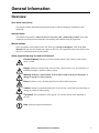
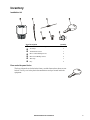
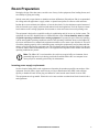
Installation InRow™ Half-Rack RC ACRC100 ACRC103 This manual is available in English on the enclosed CD. Dieses Handbuch ist in Deutsch auf der beiliegenden CD-ROM verfügbar. Deze handleiding staat in het Nederlands op de bijgevoegde cd. Este manual está disponible en español en el CD-ROM adjunto. Ce manuel est disponible en français sur le CD-ROM ci-inclus. Questo manuale è disponibile in italiano nel CD-ROM allegato. 本マニュアルの日本語版は同梱の CD-ROM からご覧になれます。 Instrukcja Obsługi w jezyku polskim jest dostepna na CD. O manual em Português está disponível no CD-ROM em anexo. Данное руководство на русском языке имеется на прилагаемом компакт-диске. 您可以从包含的 CD 上获得本手册的中文版本。 您可以从付属的CD上获得本手册的中文版本。 동봉된 CD 안에 한국어 매뉴얼이 있습니다 . American Power Conversion Legal Disclaimer The information presented in this manual is not warranted by the American Power Conversion Corporation to be authoritative, error free, or complete. This publication is not meant to be a substitute for a detailed operational and site specific development plan. Therefore, American Power Conversion Corporation assumes no liability for damages, violations of codes, improper installation, system failures, or any other problems that could arise based on the use of this Publication. The information contained in this Publication is provided as is and has been prepared solely for the purpose of evaluating data center design and construction. This Publication has been compiled in good faith by American Power Conversion Corporation. However, no representation is made or warranty given, either express or implied, as to the completeness or accuracy of the information this Publication contains. IN NO EVENT SHALL AMERICAN POWER CONVERSION CORPORATION BE LIABLE FOR ANY DIRECT, INDIRECT, CONSEQUENTIAL, PUNITIVE, SPECIAL, OR INCIDENTAL DAMAGES (INCLUDING, WITHOUT LIMITATION, DAMAGES FOR LOSS OF BUSINESS, CONTRACT, REVENUE, DATA, INFORMATION, OR BUSINESS INTERRUPTION) RESULTING FROM, ARISING OUT, OR IN CONNECTION WITH THE USE OF, OR INABILITY TO USE THIS PUBLICATION OR THE CONTENT, EVEN IF AMERICAN POWER CONVERSION CORPORATION HAS BEEN EXPRESSLY ADVISED OF THE POSSIBILITY OF SUCH DAMAGES. AMERICAN POWER CONVERSION CORPORATION RESERVES THE RIGHT TO MAKE CHANGES OR UPDATES WITH RESPECT TO OR IN THE CONTENT OF THE PUBLICATION OR THE FORMAT THEREOF AT ANY TIME WITHOUT NOTICE. Copyright, intellectual, and all other proprietary rights in the content (including but not limited to software, audio, video, text, and photographs) rests with American Power Conversion Corporation or its licensors. All rights in the content not expressly granted herein are reserved. No rights of any kind are licensed or assigned or shall otherwise pass to persons accessing this information. This Publication shall not be for resale in whole or in part. Contents General Information ........................................................ 1 Overview . . . . . . . . . . . . . . . . . . . . . . . . . . . . . . . . . . . . . . . . . . . . . . . . 1 Save these instructions . . . . . . . . . . . . . . . . . . . . . . . . . . . . . . . . . . . 1 Intended users . . . . . . . . . . . . . . . . . . . . . . . . . . . . . . . . . . . . . . . . . . 1 Manual updates . . . . . . . . . . . . . . . . . . . . . . . . . . . . . . . . . . . . . . . . . . 1 Safety symbols that may be used in this manual . . . . . . . . . . . . . . 1 Cross-reference symbol used in this manual . . . . . . . . . . . . . . . . . 2 Safety . . . . . . . . . . . . . . . . . . . . . . . . . . . . . . . . . . . . . . . . . . . . . . . . . . . 2 Inventory . . . . . . . . . . . . . . . . . . . . . . . . . . . . . . . . . . . . . . . . . . . . . . . . 3 Installation kit . . . . . . . . . . . . . . . . . . . . . . . . . . . . . . . . . . . . . . . . . . . 3 Door and side panel locks . . . . . . . . . . . . . . . . . . . . . . . . . . . . . . . . . 3 Component Identification. . . . . . . . . . . . . . . . . . . . . . . . . . . . . . . . . . . 4 Exterior . . . . . . . . . . . . . . . . . . . . . . . . . . . . . . . . . . . . . . . . . . . . . . . . 4 Interior . . . . . . . . . . . . . . . . . . . . . . . . . . . . . . . . . . . . . . . . . . . . . . . . . 5 User interface connection panel . . . . . . . . . . . . . . . . . . . . . . . . . . . . 6 Room Preparation . . . . . . . . . . . . . . . . . . . . . . . . . . . . . . . . . . . . . . . . . 7 Incoming power supply requirements . . . . . . . . . . . . . . . . . . . . . . . 7 Piping Diagrams . . . . . . . . . . . . . . . . . . . . . . . . . . . . . . . . . . . . . . . . . . 8 With CDU . . . . . . . . . . . . . . . . . . . . . . . . . . . . . . . . . . . . . . . . . . . . . . . 8 Without CDU . . . . . . . . . . . . . . . . . . . . . . . . . . . . . . . . . . . . . . . . . . . . 9 Internal piping diagram . . . . . . . . . . . . . . . . . . . . . . . . . . . . . . . . . . 10 Piping and electrical access locations . . . . . . . . . . . . . . . . . . . . . . 11 Weights and Dimensions . . . . . . . . . . . . . . . . . . . . . . . . . . . . . . . . . . 12 Installation ..................................................................... 13 Removing Doors and Panels . . . . . . . . . . . . . . . . . . . . . . . . . . . . . . . 13 Door removal . . . . . . . . . . . . . . . . . . . . . . . . . . . . . . . . . . . . . . . . . . . 13 Side panel removal . . . . . . . . . . . . . . . . . . . . . . . . . . . . . . . . . . . . . . 13 Positioning the Equipment. . . . . . . . . . . . . . . . . . . . . . . . . . . . . . . . . 14 Service access . . . . . . . . . . . . . . . . . . . . . . . . . . . . . . . . . . . . . . . . . 14 Leveling . . . . . . . . . . . . . . . . . . . . . . . . . . . . . . . . . . . . . . . . . . . . . . . 14 InRow Half-Rack RC Installation i Stabilizing the Equipment . . . . . . . . . . . . . . . . . . . . . . . . . . . . . . . . . 15 Floor brackets . . . . . . . . . . . . . . . . . . . . . . . . . . . . . . . . . . . . . . . . . . 15 Joining to enclosures . . . . . . . . . . . . . . . . . . . . . . . . . . . . . . . . . . . . 15 Mechanical Connections . . . . . . . . . . . . . . . . . . . . . . . . . . . . . . . . . . 16 Piping . . . . . . . . . . . . . . . . . . . . . . . . . . . . . . . . . . . . . . . . . . . . . . . . . 16 Connect piping . . . . . . . . . . . . . . . . . . . . . . . . . . . . . . . . . . . . . . . . . 17 Chiller . . . . . . . . . . . . . . . . . . . . . . . . . . . . . . . . . . . . . . . . . . . . . . . . . 18 CDU . . . . . . . . . . . . . . . . . . . . . . . . . . . . . . . . . . . . . . . . . . . . . . . . . . . 19 Accessories and spare parts . . . . . . . . . . . . . . . . . . . . . . . . . . . . . . 19 Filling and Purging the Equipment . . . . . . . . . . . . . . . . . . . . . . . . . . 20 Electrical Connections . . . . . . . . . . . . . . . . . . . . . . . . . . . . . . . . . . . . 22 Power connections . . . . . . . . . . . . . . . . . . . . . . . . . . . . . . . . . . . . . . 23 User interface connection pinout . . . . . . . . . . . . . . . . . . . . . . . . . . . 25 A-Link ports . . . . . . . . . . . . . . . . . . . . . . . . . . . . . . . . . . . . . . . . . . . . 26 Network port . . . . . . . . . . . . . . . . . . . . . . . . . . . . . . . . . . . . . . . . . . . 27 Modbus . . . . . . . . . . . . . . . . . . . . . . . . . . . . . . . . . . . . . . . . . . . . . . . . 28 Control connector . . . . . . . . . . . . . . . . . . . . . . . . . . . . . . . . . . . . . . . 29 Form C alarm contacts and shutdown input . . . . . . . . . . . . . . . . . . 29 Leak detector port . . . . . . . . . . . . . . . . . . . . . . . . . . . . . . . . . . . . . . . 30 Temperature sensor . . . . . . . . . . . . . . . . . . . . . . . . . . . . . . . . . . . . . 30 Specifications . . . . . . . . . . . . . . . . . . . . . . . . . . . . . . . . . . . . . . . . . . . 32 Warranty ......................................................................... 33 One-Year Factory Warranty . . . . . . . . . . . . . . . . . . . . . . . . . . . . . . . . 33 Terms of warranty . . . . . . . . . . . . . . . . . . . . . . . . . . . . . . . . . . . . . . . 33 Non-transferable warranty . . . . . . . . . . . . . . . . . . . . . . . . . . . . . . . . 33 Exclusions . . . . . . . . . . . . . . . . . . . . . . . . . . . . . . . . . . . . . . . . . . . . . 33 Warranty claims . . . . . . . . . . . . . . . . . . . . . . . . . . . . . . . . . . . . . . . . . 34 Warranty Procedures . . . . . . . . . . . . . . . . . . . . . . . . . . . . . . . . . . . . . 35 Claims . . . . . . . . . . . . . . . . . . . . . . . . . . . . . . . . . . . . . . . . . . . . . . . . . 35 Parts . . . . . . . . . . . . . . . . . . . . . . . . . . . . . . . . . . . . . . . . . . . . . . . . . . 35 ii InRow Half-Rack RC Installation General Information Overview Save these instructions This manual contains important instructions that must be followed during the installation of this equipment. Intended users This manual is intended for American Power Conversion (APC) authorized personnel. It provides component specifications and instructions for installing and commissioning the equipment. Manual updates Check for updates to this manual on the APC Web site, www.apc.com/support. Click on the User Manuals link and enter the manual part number or SKU for your equipment in the search field. See the back cover of this manual for the part number. Safety symbols that may be used in this manual Electrical Hazard: Indicates an electrical hazard which, if not avoided, could result in injury or death. Danger: Indicates a hazard which, if not avoided, could result in severe personal injury or substantial damage to product or other property. Warning: Indicates a hazard which, if not avoided, could result in personal injury or damage to product or other property. Heavy: Indicates a heavy load that should not be lifted without assistance. Caution: Indicates a potential hazard which, if not avoided, could result in personal injury or damage to product or other property. Tip Hazard: This equipment is easily tipped. Use extreme caution when unpacking or moving. Note: Indicates important information. InRow Half-Rack RC Installation 1 Cross-reference symbol used in this manual See another section of this document or another document for more information on this subject. Safety Electrical Hazard: This equipment has multiple power sources. Disconnect all power sources before servicing the equipment. Do not wear jewelry when working near energized components. Heavy: This equipment is heavy. For safety, at least two people must be present when moving or installing it. Tip Hazard: This equipment has a high center-of-gravity. Use extreme caution when unpacking and moving. When using a forklift to move the equipment, make sure to lift only from the bottom. Caution: Keep your hands, clothing, and jewelry away from moving parts. Check the equipment for foreign objects before closing the doors and starting the equipment. Note: All work should be performed by APC authorized personnel only. Follow all local and national codes when installing this equipment. For indoor use only. 2 InRow Half-Rack RC Installation Inventory na2329a Installation kit Item Description Quantity 1-in NPT to 1-in BSPT adapters 2 Tie wraps 3 Termination resistor 1 M5 x 12 mm Phillips screws 4 M4 x 8 mm Phillips screws 4 Wire clip 3 Key 2 Door and side panel locks The four side panels are locked at the factory, and the front and rear doors are not locked. Two keys are in the plastic documentation envelope located inside the equipment. InRow Half-Rack RC Installation 3 Component Identification na1542a Exterior 4 Removable rear door Door lock (front and rear doors) Side panel latch Top network wiring access Removable side panel Top supply (inlet) Caster Top condensate drain Adjustable leveling foot Top return (outlet) Display interface Top power cord access Removable front door InRow Half-Rack RC Installation na1556a Interior Air filter Bottom supply connection (optional) Top supply connection (optional) User interface connection box Top return connection (optional) Condensate pump 2-way supply valve (1-inch) Power supply unit (PSU) Flow meter Bottom condensate drain pan 3-way valve Condensate floats 2-way or 3-way valve with flow control actuator Coil 2-way valve (3/4-inch) bypass shut-off Top condensate drain pan Bottom return connection (optional) Fan Drain valve (cap is installed at factory) InRow Half-Rack RC Installation 5 na2236a User interface connection panel 6 A-Link ports Control RS-485 port Reset button Form C alarm contacts and shutdown input Ethernet port Configuration port Building management system (BMS) RS-485 port Leak detector port InRow Half-Rack RC Installation Room Preparation During the design of the data center, consider ease of entry for the equipment, floor loading factors, and accessibility to piping and wiring. Seal the room with a vapor barrier to minimize moisture infiltration. (Polyethylene film is recommended for ceiling and wall applications.) Apply rubber- or plastic-based paints to concrete walls and floors. Insulate the room to minimize the influence of exterior heat loads. Use the minimum required amount of fresh air for make up to comply with local and national codes and regulations. Fresh air imposes extreme load variation on the cooling equipment from summer to winter and causes increased operating costs. The equipment is designed as a sensible cooling air conditioning unit for in-row use in data centers. The equipment does not have humidification or dehumidification control. Room humidity must be within acceptable operating conditions before starting equipment. If operated in spaces where the humidity is in the unacceptable operating conditions section of the Operating Guidelines chart (see the InRow RC Operation and Maintenance manual) the equipment condenses excess water vapor from the air. This will exceed the pumping capacity of the condensate pump, causing the equipment to send an alarm and shut down to avoid overflowing the condensate pan. The condensate pump runs until the fluid level in the pan is reduced, and the alarm is automatically reset. The equipment self-regulates in this manner until normal operating conditions are present. Note: The InRow RC is not intended to be used in an occupied office environment, due to potentially high noise levels during peak loads. Install the InRow RC in a computer room where people are normally present only for maintenance. Incoming power supply requirements See the electrical rating label on the equipment to determine the maximum possible current draw of the equipment. Provide either a single outlet circuit or a Power Distribution Unit (PDU) with sufficient capacity to handle all loads. Do not plug two InRow RC units into the same branch circuit or PDU. The equipment must be grounded. Electrical service must conform to national and local electrical codes and regulations. InRow Half-Rack RC Installation 7 Piping Diagrams With CDU To customersupplied chiller Top piping InRow RC CDU Supports up to 12 units Bottom piping CDU InRow RC Supports up to 12 units na2608a To customersupplied chiller Flex hose or copper tubing Y-strainer with 20 mesh screen (field installed) Copper tubing Shutoff valve (field-installed) Note: Install isolation valves and particulate strainers with 20 mesh stainless steel screen (opening size = 865 micron) in the supply line between the chiller and the CDU. If the system is to be set up as an isolated loop - a chiller and pipe layout, dedicated only to supplying RC units and no other equipment - the strainer may be placed in the piping circuit before the pump. Thoroughly flush the system to remove all debris and process chemicals. Note: Top or bottom entry can be chosen individually for each type of connection, i.e. power, condensate drain, humidifier water supply, chilled water supply and chilled water return. Top piping configurations will have the same valves and strainers as bottom piping configurations. 8 InRow Half-Rack RC Installation Without CDU Top piping To customersupplied chiller InRow RC InRow RC Bottom piping InRow RC InRow RC na2609a To customersupplied chiller Flex hose or copper Copper tubing Y-strainer with 20 mesh screen (field installed) Shutoff valve (field-installed) Circuit setter Note: Install isolation valves and particulate strainers with 20 mesh stainless steel screen (opening size = 865 micron) in the supply line between the chiller and the CDU. If the system is to be set up as an isolated loop - a chiller and pipe layout, dedicated only to supplying RC units and no other equipment - the strainer may be placed in the piping circuit before the pump. Thoroughly flush the system to remove all debris and process chemicals. Note: Top or bottom entry can be chosen individually for each type of connection, i.e. power, condensate drain, humidifier water supply, chilled water supply and chilled water return. Top piping configurations will have the same valves and strainers as bottom piping configurations. InRow Half-Rack RC Installation 9 na1736b Internal piping diagram 10 Entering water union (top piping) Entering water union (bottom piping) Leaving water union (top piping) Bottom condensate pan 3-way actuator control valve—3/4 in Bottom coil Bypass shutoff ball valve—3/4 in Top condensate pan Condensate drain Top coil Leaving water union (bottom piping) Flow meter Condensate pump Inlet shutoff valve—1 in InRow Half-Rack RC Installation 117 (4.6) 80 (3.15) 152.00 (5.98) 67.80 (2.67) 48.00 (1.89) 0 222 (8.74) 149 (5.87 ) 73 (2.87) 50 (1.97) 0 Piping and electrical access locations 0 114 (4.59) 152 (5.98) 190.55 (7.50) 229 (9.02) 507.50 (19.98) Bottom na1557a Top Supply 173 (6.80) 414 ( 16.28) Return Interior pipe dimensions Supply 629 ( 24.78) 445 (17.51) Return Dimensions are shown in mm (in). Power connections Power connections 1-in NPT female (return) Low voltage input wiring (customer) 1-in NPT female (supply) 1-in NPT female (supply) Low voltage input wiring (customer-supplied) Condensate line—0.25 in ID/0.38 in OD Cable trough location 1-in NPT female (return) Condensate line—0.25 in ID/0.38 in OD InRow Half-Rack RC Installation 11 na1551a Weights and Dimensions Dimensions are shown in mm (in). Net weight (equipment only) 12 162.77 kg (358.5 lb) InRow Half-Rack RC Installation Installation Removing Doors and Panels Door removal Warning: Do not open doors and panels if the equipment is operating. na1571a Caution: Spring latches can be damaged if the doors are placed against an object with the latches contacting the object. na1554a Side panel removal InRow Half-Rack RC Installation 13 Positioning the Equipment Service access na1565a An area of 1143 mm (45 in) of clear floor space in front and 914.4 mm (36 in) in back of the equipment is required for service. All required maintenance can be performed from the front or back of the equipment. Dimensions are shown in mm (in). Leveling The leveling feet provide a stable base if the floor is uneven, but cannot compensate for a badly sloped surface. You can remove the casters and leveling feet to allow the equipment to rest directly on the floor. 14 InRow Half-Rack RC Installation na1572a Once the equipment is in its intended location, use a screwdriver to turn each leveling foot until it makes contact with the floor. Adjust each foot until the equipment is level and plumb. Stabilizing the Equipment Floor brackets To prevent the equipment from moving from its final location (if it is not joined with an enclosure), use the included bolt-down kit (AR7701). Follow the installation instructions included with the kit. Joining to enclosures NetShelter® SX enclosure. Two joining brackets are installed on the front and rear of the equipment. Depending on how the holes on the joining brackets are used, you have the option of either 24-in or 600-mm spacing. 2. Locate the four joining brackets on the equipment. Rotate each bracket 90° toward the adjoining enclosure so that the bracket is parallel to the floor. na1573a 1. Remove the front and two rear doors from the equipment. See “Door removal” on page 13. 3. Install the brackets using the Phillips screws provided with the equipment. NetShelter VX enclosure. The equipment may be joined to a NetShelter VX enclosure (24-in spacing only) by using an accessory kit (AR7602), sold separately. InRow Half-Rack RC Installation 15 Mechanical Connections Piping Hot Aisle Containment Water. Install shutoff valves for routine service and emergency isolation of the equipment. When a cooling distribution unit (CDU) is not used, you must install circuit setters to regulate the chilled water flow for each InRow RC air conditioner. See piping diagrams beginning on page 8. CDU NetShelter NetShelter NetShelter Top piping examples shown UPS PDU Layout and piping NetShelter RC considerations. InRow PDU UPS NetShelter RC NetShelter NetShelter RC NetShelter CDU na1941a Fluid pipes are not allowed directly above electrical equipment. All piping must be installed above the aisles as shown. If any piping makes a turn, or must be routed over electrical equipment, there must be a drip tray under the pipe that will protect the equipment from condensation and leaks. All piping must be kept separate from any electrical runs or wiring. NetShelter NetShelter RC NetShelter NetShelter NetShelter RC NetShelter NetShelter RC NetShelter NetShelter Insulation. Insulate water lines to protect personnel and to minimize condensation. Note: Using either tape or glue, completely seal the insulation boots covering the unused supply and return connections. 16 InRow Half-Rack RC Installation Connect piping See “Piping Diagrams,” beginning on page 8, for recommended valve, flexible adapter, and strainer installation locations. 1. Route all piping to the InRow RC in compliance with all local and national codes. Note: Circuit setters are required to regulate the flow of chilled water to each piece of equipment. When a CDU is used in conjunction with the equipment, circuit setters are not required, as the CDU provides the flow-regulating function. Note: The figure shows a top piping installation with a PEX fitting. Bottom piping installations or rigid piping fittings are handled similarly. 2. Disassemble the union on the entering or exiting water line: a. Remove the nut from the body . b. Remove the disc and gasket . Save the gasket. c. The disc prevents water flow through the union. Discard the disc . 3. Repeat step 2 for the union on the other water line. 4. Assemble the union on the entering or exiting water line: a. Use thread sealant and thread sealing tape in accordance with local and national codes. b. Slide the nut onto the fitting . c. Seat the gasket into the body . d. Tighten the body onto the nut , using a properlysized open end wrench. na2239a 5. Repeat steps 1 through 4 for the union on the other water line. Warning: Do not exceed the lift or the run length of the drain system. InRow Half-Rack RC Installation na1575a Condensate pump. The pump is factory-wired and piped internally to the lower condensate pan. The pump is capable of moving liquid a maximum of 15.2 m (50 ft), including a maximum lift of 4.9 m (16 ft). For example, if your lift is 3 m (10 ft), you have 12.2 m (40 ft) of usable run. The pump also uses an on-board condensate high level float switch, which is wired into the InRow RC alarm input for local and remote alarm capabilities. 17 Condensate pump drain connection. Condensate drain line Note: Sufficient PVC drain line is supplied to route the drain to the outside of the equipment. To route the drain line to a remote drain, obtain additional hardware. Condensate pump drain installation. The condensate drain line is coiled inside the equipment, allowing you to route the condensate drain line for either top or bottom use. See the table “Piping and electrical access locations” on page 11 for more information. Use the provided grommets to properly secure and protect the condensate drain line. na2271a Warning: To prevent equipment damage from condensate, do not leave the condensate drain line coiled inside the equipment. Route the condensate drain line out the top or bottom of the equipment. See “Condensate pump drain installation” on this page. Top routing Note: Comply with all local codes when installing the condensate drain line to the proper drain system. Bottom routing na1576a Warning: Failure to properly route the condensate drain line before operation could result in water damage. Chiller There are three types of chillers to which the equipment can be connected: • APC size-matched chiller/thermal storage system • Building chilled water system • Existing dedicated chiller See the chiller manufacturer’s installation, operation, and maintenance manuals for proper installation procedures. 18 InRow Half-Rack RC Installation CDU See the CDU Installation manual for proper installation procedures. Accessories and spare parts Accessories are available for the equipment, including flexible pipe adapters, data troughs, data partitions, and height adapters for use with other APC equipment. For more information, contact APC at a number on the back cover of this manual. Many serviceable components are available as spare parts. For more information, contact APC at a number on the back cover of this manual. InRow Half-Rack RC Installation 19 Filling and Purging When the equipment is properly piped, begin the filling process (top piping configuration shown). Electrical Hazard: Ensure both electrical connections are disconnected before introducing water into the equipment. 1. Open the 2-way supply valve and the 2-way bypass shutoff valve. 2. Using a 2.5-mm hex key, turn the flow control actuator to the fully open position. Fully open 2-way supply valve Fully closed Flow control actuator Fully open Full bypass 2-way bypass shutoff valve na1767a Fully open Fully closed 20 InRow Half-Rack RC Installation 3. Slightly open the top coil vent. 4. At the water supply, open the appropriate valves to begin letting water slowly enter the equipment. 5. At the equipment, close the top coil vent when water begins slowly flowing out of the vent. Top coil vent a. Open all valves (no greater than 76 l/m [20 gpm]), allowing the water supply to reach the highest possible flow to the equipment for 45 seconds. na1768a 6. At the water supply: b. Close the valves to a 3.8–11.4 l/m (1–3 GPM) flow for 60 seconds. c. Open the valves to maximum flow for another 45 seconds. d. Balance the system to provide the designed flow rate to all equipment. InRow Half-Rack RC Installation 21 Electrical Connections The following electrical connections are required in the field: • Feeds A and B • A-Link • Network Management Card • Temperature sensor • Communication (building management system) See the electrical schematic, located on the lid of the electrical box, for all electrical connections. All electrical connections must be in accordance with national and local codes. See the InRow RC nameplate for voltage and current requirements. A power disconnect is required to isolate each InRow RC for maintenance and service. All low-voltage connections, including data and control connections, must be made with properly insulated wires. The low-voltage connections must have 300-V minimum insulation. Electrical Hazard: Potentially dangerous and lethal voltages exist within this InRow RC. More than one disconnect switch may be required to energize or de-energize this equipment. Observe all cautions and warnings. Failure to do so could result in serious injury or death. Only qualified service and maintenance personnel should work on this equipment. Warning: Use a voltmeter to ensure that power is turned off before making any electrical connections. Note: Single phase service is required. Electrical service must conform to national and local electrical codes. The InRow RC is grounded through the power cord. 22 InRow Half-Rack RC Installation Power connections Warning: The equipment has two power inputs for redundancy. Disconnect both before performing any service. Power cords may be routed through the top of the equipment (standard) or through the bottom (optional). Top wiring configuration Screws Top power cord entrance (standard). 1. Route power cords through the equipment to the top power cord access, as shown. 2. Push the power cords through the hole at the top power cord entrance. 3. Secure the plate to the underside of the equipment top with four Phillips screws (provided). Plate na1581a 4. Secure the power cords at appropriate locations inside the equipment using the provided tie wraps. Bottom power entrance Bottom wiring configuration (optional). 1. Remove the blank plate from the bottom power cord entrance. Save the plate and the four Torx screws. 2. Route the power cords through the equipment to the bottom power cord access, as shown. 3. Feed the power cords through the hole at the bottom power cord entrance and secure the plate to the bottom of the equipment with the four Torx screws you saved in step 1. 4. Secure the blank plate to the top power entrance with four Phillips screws (provided). 5. Secure the power cords at appropriate locations inside the equipment using the provided wire ties. InRow Half-Rack RC Installation 23 Feeds A and B. The equipment is capable of receiving power through one of two separate feeds, feed A or feed B. Use the display interface to configure the unit to receive power through feed A, feed B, or both). If connected, feed B is the primary power input to the equipment by default; feed A is the backup power input. The equipment receives power through feed B regardless of whether feed A is receiving power. If power is removed from feed B, feed A takes over and supplies power to the equipment (if feed A is connected). Connect the feed A and feed B cables to individual, breaker-controlled branch circuits or to PDUs backed by separate Uninterruptible Power Supplies (UPSs). Note: Feed A and feed B must not use the same branch circuit, PDU, or UPS. For more information on configuring power input feeds, see the InRow RC Operation and Maintenance manual. 24 InRow Half-Rack RC Installation User interface connection pinout Shutdown input contacts and alarm output contacts CONTROL na1579a MODBUS A-Link port Pin 1=High; Pin 2=Low; Pins 3, 6=Perf Power; Pins 4, 5=Ground 24 Vdc (bias) Reset button 12 Vdc (bias) Network port Return (bias) Pins 1-8 = Standard RJ-45 Shield/ground NO (normally open contact) A-=True COM (common contact) B+=True NC (normally closed contact) Shutdown - RS-232 console port (see the InRow RC Service Manual) Shutdown + Leak detector (AP9325) InRow Half-Rack RC Installation 25 A-Link ports Note: All input and output connections should be wired as Class 2 circuits. Depending on the equipment configuration, additional control connections may be required for the A-Link remote communications through APC Network Management Card support or other equipmentmonitoring software. A special RJ-45 terminator is provided and must be installed if both A-Link ports are not otherwise used, as shown. Second InRow RC Last InRow RC na2243a First InRow RC 26 RJ-45 terminator (provided) A-Link cable InRow Half-Rack RC Installation Network port Second InRow RC Switch/Hub Last InRow RC na2247a First InRow RC LAN cable (10/100 Base-T) InRow Half-Rack RC Installation 27 Modbus First InRow RC Second InRow RC Last InRow RC na2248a Modbus MASTER 28 150Ω termination resistor (provided) Modbus cable (RS-485) InRow Half-Rack RC Installation na2249a Control connector 150Ω termination resistor (provided) Control cable (RS-485) Peripheral device (example: chiller) na2250a Form C alarm contacts and shutdown input A relay internal to the user interface is typically controlled by a user-defined alarm (malfunctioning fans, for example). Before an alarm is detected, the voltage on the COM terminal is routed to the NC terminal. When the alarm is activated, the relay is energized, causing the voltage on the COM terminal to be routed to the NO terminal. The NO and NC terminals may be connected to remote indicator lights, a warning buzzer, or another device to alert an operator to the presence of an alarm condition. A remote disconnect switch may be connected to the shutdown inputs. InRow Half-Rack RC Installation 29 Leak detector port na1584a Rope water detector (AP9325). Up to four optional rope water detectors can be installed in series. The rope water detector connects to the RJ-45 leak detector port located at the top of the interface box. See the “Rope Water Detector” installation sheet, supplied with the kit, for installation and setup information. Temperature sensor Remote temperature sensor na2271a Caution: The remote temperature sensor comes coiled inside the equipment as shown, and must be mounted as follows, or the equipment will not operate properly. gen0744a The remote temperature sensor monitors the room temperature, monitoring the environment surrounding the cooling equipment to ensure that the conditioned air is cooling the area. 30 InRow Half-Rack RC Installation Install the temperature sensor. 1. Insert the rack temperature sensor connector in the temperature sensor port at the user interface. See “User interface connection pinout” on page 25. a. For a top installation, push the rack temperature sensor through the wire channel located at the top of the equipment in the left hand side just above the user interface connectors. Temperature sensor Wire clip 2. Route the sensor through either the top or the bottom of the adjacent server rack. 3. Secure the temperature sensor cable to the front door of the adjacent server rack at multiple locations using the provided wire clips as shown. See “Installation kit” on page 3. gen0767a b. For a bottom installation, route the sensor through the wire clamps along the electrical panel and then push the sensor through the customer access hole in the bottom of the equipment. The sensors must be installed where lack of sufficient cooling air is most likely. The optimum position of the rack temperature sensors will vary from installation to installation, but should be located in the airflow to allow accurate readings. Servers most likely to have insufficient air or inadequately cooled air due to the recirculation of hot air from the hot aisle include: a. Servers positioned at the top of a rack. b. Servers positioned at any height in the last rack at an open end of a row. c. Servers positioned behind flow-impairing obstacles such as building elements. d. Servers positioned in a bank of high-density racks. e. Servers positioned next to racks with Air Removal Units (ARU). f. Servers positioned very far from the equipment. g. Servers positioned very close to the equipment. InRow Half-Rack RC Installation 31 Specifications Electrical Input voltage 100-240 V; 50/60 Hz; 1 Ph Rated current 10.1 A at 100 V 9.2 A at 120 V 5.1 A at 208 V 4.6 A at 230 V 4.4 A at 240 V Condensate pump 5 l/h (1.3 GPH), 4.9-m (16-ft) vertical rise, 15-m (50-ft) horizontal run Physical Physical dimensions W xDxH 300 x 1068.9 x 1991.1 mm (11.80 x 42.08 x 78.39 in) Net weight (InRow RC only) 162.77 kg (358.5 lb) Shipping weight 192.77 kg (425.0 lb) 355.62 kg (784.0 lb) Single Double Environmental Cooling capacity 18.2 kW (62,000 BTU/hour) total at 29.4°C (85°F)/31% humidity and 7.2ºC (45ºF) entering chilled water Airflow–high 76.45 m3/minute (2900 CFM) Sound pressure 75 dBA at2700SCFM and 1.0 m in front of equipment (ref 20 μPa) 78.5 dBA at 2,900 SCFM and 1.0 m in front of equipment (ref 20 μPa) Entering air (maximum) 41ºC (105ºF) Entering water 7.22°C at 45 l/m (45°F at 13.0 GPM) Exiting water 12.77°C at pressure drop = 50 kPa (55°F at pressure drop = 17ft-H2O) Recommended coolant requirements Entering water temperature 7.2°C–12.7ºC (45°F–55ºF) Flow rate (maximum) 77.6 l/m (20.5 GPM) Water-side pressure drop 5.18 m-H2O at 49.21 l/m (17 ft-H2O at 13 GPM) Maximum operating pressure 2068 kPa (300 psig) for hard-piped installations 1034 kPa (150 psig) for PEX installations Note: For additional capacity and performance data, consult the InRow RC Technical Data Manual. 32 InRow Half-Rack RC Installation Warranty One-Year Factory Warranty The limited warranty provided by American Power Conversion (APC®) in this Statement of Limited Factory Warranty applies only to products you purchase for your commercial or industrial use in the ordinary course of your business. Terms of warranty American Power Conversion warrants its products to be free from defects in materials and workmanship for a period of one year from the date of purchase. The obligation of APC under this warranty is limited to repairing or replacing, at its sole discretion, any such defective products. This warranty does not apply to equipment that has been damaged by accident, negligence or misapplication or has been altered or modified in any way. Repair or replacement of a defective product or part thereof does not extend the original warranty period. Any parts furnished under this warranty may be new or factoryremanufactured. Non-transferable warranty This warranty extends only to the original purchaser who must have properly registered the product. The product may be registered at the APC Web site, www.apc.com. Exclusions APC shall not be liable under the warranty if its testing and examination disclose that the alleged defect in the product does not exist or was caused by end user’s or any third person’s misuse, negligence, improper installation or testing. Further, APC shall not be liable under the warranty for unauthorized attempts to repair or modify wrong or inadequate electrical voltage or connection, inappropriate on-site operation conditions, corrosive atmosphere, repair, installation, start-up by non-APC designated personnel, a change in location or operating use, exposure to the elements, Acts of God, fire, theft, or installation contrary to APC recommendations or specifications or in any event if the APC serial number has been altered, defaced, or removed, or any other cause beyond the range of the intended use. THERE ARE NO WARRANTIES, EXPRESS OR IMPLIED, BY OPERATION OF LAW OR OTHERWISE, OF PRODUCTS SOLD, SERVICED OR FURNISHED UNDER THIS AGREEMENT OR IN CONNECTION HEREWITH. APC DISCLAIMS ALL IMPLIED WARRANTIES OF MERCHANTABILITY, SATISFACTION AND FITNESS FOR A PARTICULAR PURPOSE. APC EXPRESS WARRANTIES WILL NOT BE ENLARGED, DIMINISHED, OR AFFECTED BY AND NO OBLIGATION OR LIABILITY WILL ARISE OUT OF, APC RENDERING OF TECHNICAL OR OTHER ADVICE OR SERVICE IN CONNECTION WITH THE PRODUCTS. THE FOREGOING WARRANTIES AND REMEDIES ARE EXCLUSIVE AND IN LIEU OF ALL OTHER WARRANTIES AND REMEDIES. THE WARRANTIES SET FORTH ABOVE CONSTITUTE APC’S SOLE LIABILITY AND PURCHASER’S EXCLUSIVE REMEDY FOR ANY BREACH OF SUCH WARRANTIES. APC WARRANTIES EXTEND ONLY TO PURCHASER AND ARE NOT EXTENDED TO ANY THIRD PARTIES. InRow Half-Rack RC Installation 33 IN NO EVENT SHALL APC, ITS OFFICERS, DIRECTORS, AFFILIATES OR EMPLOYEES BE LIABLE FOR ANY FORM OF INDIRECT, SPECIAL, CONSEQUENTIAL OR PUNITIVE DAMAGES, ARISING OUT OF THE USE, SERVICE OR INSTALLATION, OF THE PRODUCTS, WHETHER SUCH DAMAGES ARISE IN CONTRACT OR TORT, IRRESPECTIVE OF FAULT, NEGLIGENCE OR STRICT LIABILITY OR WHETHER APC HAS BEEN ADVISED IN ADVANCE OF THE POSSIBILITY OF SUCH DAMAGES. SPECIFICALLY, APC IS NOT LIABLE FOR ANY COSTS, SUCH AS LOST PROFITS OR REVENUE, LOSS OF EQUIPMENT, LOSS OF USE OF EQUIPMENT, LOSS OF SOFTWARE, LOSS OF DATA, COSTS OF SUBSTITUENTS, CLAIMS BY THIRD PARTIES, OR OTHERWISE. NO SALESMAN, EMPLOYEE OR AGENT OF APC IS AUTHORIZED TO ADD TO OR VARY THE TERMS OF THIS WARRANTY. WARRANTY TERMS MAY BE MODIFIED, IF AT ALL, ONLY IN WRITING SIGNED BY AN APC OFFICER AND LEGAL DEPARTMENT. Warranty claims Customers with warranty claims issues may access the APC customer support network through the Support page of the APC Web site, www.apc.com/support. Select your country from the country selection pull-down menu at the top of the Web page. Select the Support tab to obtain contact information for customer support in your region. 34 InRow Half-Rack RC Installation Warranty Procedures Claims To obtain service under the warranty, contact APC Customer Support (see the back cover of this manual for contact information). You will need the model number of the Product, the serial number, and the date purchased. A technician will also ask you to describe the problem. If it is determined that the Product will need to be returned to APC, you must obtain a returned material authorization (RMA) number from APC Customer Support. Products that must be returned must have the RMA number marked on the outside of the package and must be returned with transportation charges prepaid. If it is determined by APC Customer Support that on-site repair of the Product is allowed, APC will arrange to have APC authorized service personnel dispatched to the Product location for repair or replacement, at the discretion of APC. Parts • APC warrants the parts of their systems for 1 year from the date of commissioning or 18 months from the ship date. This warranty only covers the cost of the part and not the labor for installation. • Calls for warranty parts requests need to have specific unit information (serial number, model number, job number) to allow proper identification and processing of the warranty part transaction. • A purchase order may be required to issue any warranty parts. An invoice will be sent once the parts are shipped to the field. You have 30 days to return the defective parts to APC. After 30 days, the warranty invoice will be outstanding, and payment of the invoice will be expected in full. • Return authorization documentation will be sent with the replacement part. This documentation must be sent back with the defective part to APC for proper identification of the warranty return. Mark the warranty return number on the outside of the package. • After the part has been received at APC, we will determine the status of the credit based on the findings of the returned part. Parts that are damaged from lack of maintenance, misapplication, improper installation, shipping damage, or acts of man/nature will not be covered under the parts warranty. • Any warranty parts request received before 1:00 PM EST will be shipped same-day standard ground delivery. Any costs associated with Next Day or Airfreight will be the responsibility of the party requesting the part. • Return freight of warranty parts to APC is the responsibility of the party returning the part. InRow Half-Rack RC Installation 35 APC Worldwide Customer Support Customer support for this or any other APC product is available at no charge in any of the following ways: • Visit the APC Web site to access documents in the APC Knowledge Base and to submit customer support requests. – www.apc.com (Corporate Headquarters) Connect to localized APC Web sites for specific countries, each of which provides customer support information. – www.apc.com/support/ Global support searching APC Knowledge Base and using e-support. • Contact an APC Customer Support center by telephone or e-mail. – Regional centers Direct InfraStruXure Customer Support Line (1)(877)537-0607 (toll free) APC headquarters U.S., (1)(800)800-4272 (toll free) Canada Latin America (1)(401)789-5735 (USA) Europe, Middle East, Africa (353)(91)702000 (Ireland) Western Europe (inc. Scandinavia) +800 0272 0272 Japan (0) 36402-2001 Australia, New Zealand, (61) (2) 9955 9366 (Australia) South Pacific area – Local, country-specific centers: go to www.apc.com/support/contact for contact information. Contact the APC representative or other distributor from whom you purchased your APC product for information on how to obtain local customer support. Entire contents copyright 2007 American Power Conversion Corporation. All rights reserved. Reproduction in whole or in part without permission is prohibited. APC, the APC logo, NetShelter, and InRow are trademarks of American Power Conversion Corporation. All other trademarks, product names, and corporate names are the property of their respective owners and are used for informational purposes only. 990-2402B-001 *990-2402B-001* 12/2007