1
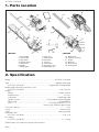
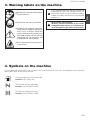
eHT752S / eHT602D
115 34 56-10 (001)
G
B
OWNER’S MANUAL
HEDGE TRIMMER
eHT752S
eHT602D
Original Language
GB-1
eHT752S / eHT602D
EXPLANATION OF SYMBOLS AND SAFETY WARNINGS
eHT752S
WARNING!!!
RISK OF DAMAGING HEARING
Wear head, eye and ear protection.
eHT602D
WARNING!!!
RISK OF DAMAGING HEARING
Wear head, eye and ear protection.
MODEL
eHT752S
eHT602D
21.7 cm3
21.7 cm3
SOUND LEVEL1)
ISO 10517
ISO 11094
LpAV
LWA (guaranteed)
94 dB(A)
104 dB(A)
91 dB(A)
102 dB(A)
VIBRATION LEVEL2)
ISO 10517
ahv, eq
4.9 m/s2
4.1 m/s2
* Specifications are subject to change without notice
1) Noise emissions in the environment measured as sound power (LWA) in conformity with EC directive 2000/14/EC.
Reported soundpower level for the machine has been measured with the original cutting attachment that gives
the highest level.
The difference between guaranteed and measured sound power is that the guaranteed sound power also includes dispersion in the measurement result and the variations between different machines of the same model
according to Directive 2000/14/EC.
Reported data for equivalent sound pressure level (LpAeq) at the operator’s ear for the machine has a typical
statistical dispersion (standard deviation) of 1 dB (A).
2) Reported data for equivalent vibration level (ahv,eq) at the control handle has a typical statistical dispersion (standard deviation) of 1 m/s2.
APPROVAL NUMBER OF CE EXHAUST EMISSION REGULATION
e13*97/68SH2G3*2002/88*0109*02
GB-2
eHT752S / eHT602D
EC DECLARATION OF CONFORMITY
(Applies to Europe only)
The undersigned manufacturer,
Husqvarna Zenoah Co.,Ltd.,
1-9, Minamidai, Kawagoe, Saitama, Japan,
declares under sole responsibility that the following products referred to in this
declaration conform with the requirement of the following COUNCIL’S DIRECTIVE.
G
B
The products referred to are :
DESIGNATION
MANUFACTURER
MODELS
: Hedge trimmers
: Husqvarna Zenoah Co., Ltd.
: eHT752S
eHT602D
SERIAL NUMBERS DATING : 2010 and onwards
(The year is cleary stated on the rating plate,
follwed by the serial number)
This declaration conform with :
・DIRECTIVE 2006/42/EC
(The following standards have been applied: ISO 12100-1,-2, FprEN 15503: 2009)
・DIRECTIVE 2004/108/EC
(The following standards have been applied: EN 61000-6-1, EN 55012 (CISPR 12: 2005))
・DIRECTIVE 2000/14/EC
conformity assessment procedure followed ANNEX V
(The following standards have been applied: ISO 11094)
・DIRECTIVE 2002/88/EC
・EN774 : 1996
Date :
29 December 2009
Signature :
Kiyoshi Honda
General Manager, Development Center
Authorised representative :
Husqvarna AB
SE-561 82 Huskvarna, Sweden
Person authorised to compile the technical file :
Bo R Jonsson
SE-561 82 Huskvarna, Sweden
SAFETY FIRST
Instructions contained in warnings within this manual marked
with a
symbol concern critical points which must be taken
into consideration to prevent possible serious bodily injury, and
for this reason you are requested to read all such instructions
carefully and follow them without fail.
WARNINGS IN THE MANUAL
WARNING
This mark indicates instructions, which must be followed in order to prevent accidents, which could lead to serious bodily injury or death.
IMPORTANT
This mark indicates instructions, which must be followed, or it
leads to mechanical failure, breakdown, or damage.
Contents
1.
2.
3.
4.
5.
6.
7.
8.
9.
10.
11.
Parts location .................................................. 4
Specifications ................................................. 4
Warning labels on the machine ...................... 5
Symbols on the machine ................................ 5
For safe operation ........................................... 6
Fuel ................................................................. 9
Operation ...................................................... 10
Maintenance ................................................. 12
Storage ......................................................... 15
Disposal ........................................................ 15
Troubleshooting guide .................................. 15
NOTE
This mark indicates hints or directions useful in the use of the
product.
GB-3
eHT752S / eHT602D
1. Parts location
8
8
15
15
14
14
16
19
12
12
4
6
6
1
4
13
9
7
13
7
11
11
17
10
10
1
3
5
9
5
3
eHT752S
1.
2.
3.
4.
5.
6.
7.
Front handle
Rear handle
Stop switch
Throttle trigger
Safety lock
Blades
Blade guard
20
18
2
8.
9.
10.
11.
12.
13.
14.
Gear case
Starter knob
Fuel tank
Fuel cap
Choke lever
Air cleaner cover
Spark plug cap
eHT602D
15.
16.
17.
18.
19.
20.
Blade cover
Operator’s manual
Socket
Allen key
Plate receive
Locking lever
2. Specification
Model ........................................................................................... eHT752S / eHT602D
Type ................................................................................................ double-action type
eHT752S / eHT602D .................................................. Single blade / Double blade
Blade length (from the tip of Gear Case)
eHT752S / eHT602D ......................................................................... 670 / 530 mm
Engine
Model ............................................................................................. Zenoah G20LH
Displacement ........................................................................................... 21.7 cm3
Carburetor .................................................................................... Diaphragm type
Ignition system ..................................................... I.C.controlled flywheel magneto
Spark plug ........................................................................................ NGK BPMR7A
Fuel ............................................................................. mixture (Gasoline 50 : Oil 1)
(when using ZENOAH genuine oil)
Fuel tank capacity ................................................................................................. 0.4 L
Starter ...................................................................................................... Recoil starter
Clutch .................................................................................................. Centrifugal type
Reduction ratio
eHT752S / eHT602D .............................................................................. 4.78 / 4.78
Dry weight
eHT752S / eHT602D ............................................................................. 4.7 / 4.6 kg
Specifications are subject to change without notice.
GB-4
2
eHT752S / eHT602D
3. Warning labels on the machine
(1)Read
owner's manual before operat(1)
ing this machine.
(2)Wear head, eye and ear protection.
(3)Handling this machine improperly
could result in accidents causing serious injury or death. Read this
manual carefully and practice using
the hedge-trimmer until you are fully
acquainted with all operations and
have learned to use it correctly.
If warning label peels off or becomes soiled and
impossible to read, you should contact the
dealer from which you purchased the product
to order new labels and affix them in the required
location(s).
Never modify your machine.
We won’t warrant the machine, if you use the
remodeled hedge trimmer or if you don’t observe the proper usage written in the manual.
(4)This is extremely sharp and can easily cause cuts.
4. Symbols on the machine
For safe operation and maintenance, symbols are carved in relief on the machine. According to these indications,
please be careful not to make a mistake.
The port to refuel the “MIX GASOLINE”
Position: FUEL TANK CAP
The direction to close the choke
Position: AIR CLEANER COVER
The direction to open the choke
Position: AIR CLEANER COVER
GB-5
G
B
eHT752S / eHT602D
5. For safe operation
1. THIS MACHINE CAN CAUSE
SERIOUS INJURIES. Read this
manual carefully until you completely understand and follow all
safety and operating instructions. Also, know how to stop the
machine quickly in an emergency.
2. Keep this manual handy so that
you may refer to it later whenever any questions arise. Also
note, if you have any questions
which cannot be answered
herein, contact the dealer from
whom you purchased the product.
3. Always be sure to include this
manual when selling, lending, or
otherwise transferring the ownership of this product.
4. Never allow children or anyone
unable to fully understand the
directions given in the manual
to use the machine.
WORKING CONDITION
1. When using the product, you
should wear proper clothing and
protective equipment.
(1) Helmet
(2) Ear protectors
(3) Protection goggles or face
protector
(4) Thick work gloves
(5) Non-slip-sole work boots
2. And you should carry with you.
(1) Attached tools
(2) Properly reserved fuel
(3) Spare blade
(4) Things to notify your working
area (rope, warning signs)
(5) Whistle (for collaboration or
emergency)
(6) Hatchet or saw (for removal of
obstacles)
(7) First-aid kit
3. Do not wear loose clothing, jewelry, short trousers, sandals, or go
barefoot. Do not wear anything
which might be caught by a moving part of the unit. Secure hair
so it is above shoulder length.
WORKING CIRCUMSTANCE
1. Never start the engine inside a
closed room or building. Exhaust
GB-6
gases contain dangerous carbon
monoxide.
2. Never use the product,
a. when the ground is slippery
or when you can’t maintain a
steady posture.
b. At night, at times of heavy fog,
or at any other times when
your field of vision might be
limited and it would be difficult to gain a clear view of the
working area.
c. During rain, during storms at
times of strong or gale-force
winds, or at any other times
when weather conditions
might make it unsafe to use
the product.
WORKING PLAN
1. You should never use the product when under the influence of
alcohol, when suffering from exhaustion or lack of sleep, when
suffering from drowsiness as a result of having taken cold medicine
or at any other time when a possibility exists that your judgment
might be impaired or that you
might not be able to operate the
product properly and in a safe
manner.
2. When planning your work schedule, allow plenty of time to rest.
Limit the amount of time over
which the product is to be used
continuously to somewhere
around 30 ~ 40 minutes per session, and take 10 ~ 20 minutes of
rest between work sessions. Also
try to keep the total amount of
work performed in a single day
under 2 hours or less.
WARNING
1. If you don’t observe the working
time, or working manner (See
“USING THE PRODUCT”), Repetitive Stress Injury (RSI) could
occur.
If you feel discomfort, redness and
swelling of your fingers or any
other part of your body, see a doctor before getting worse.
2. To avoid noise complaints, in general, operate product between
8 a.m. and 5 p.m. on weekdays
and 9 a.m. to 5 p.m. on weekends.
eHT752S / eHT602D
5. For safe operation
IMPORTANT
Check and follow the local regulations as to sound level and hours of
operations for the product.
BEFORE STARTING
THE ENGINE
1. The area within a perimeter of
15 m of the person using the
product should be considered a
hazardous area into which no one
should enter. If necessary, yellow
warning rope, warning signs
should be placed around the perimeter of the area. When work is
to be performed simultaneously
by two or more persons, care
should also be taken to constantly
look around or otherwise check
for the presence and locations of
other people working so as to
maintain a distance between
each person sufficient to ensure
safety.
2. Check the condition of working
area to avoid any accident by hitting hidden obstacles such as
stumps, stones, cans, or broken
glass.
IMPORTANT
Remove any obstacle before beginning work.
3. Inspect the entire unit for loose
fasteners and fuel leakage. Make
sure that the cutting attachment
is properly installed and securely
fastened.
STARTING THE ENGINE
1. Keep bystanders, especially children, and animals at least 15 m
away from the operating point. If
you are approached, immediately
stop the engine.
2. The product is equipped with a
centrifugal clutch mechanism, so
the cutting attachment begins to
move as soon as the engine is
started by putting the throttle into
the start position. When starting
the engine, place the product
onto the ground in a flat clear area
and hold it firmly in place so as to
ensure that neither the cutting
part nor the throttle come into
contact with any obstacle when
the engine starts.
WARNING
• Never place the throttle into the
high-speed position when starting the engine.
• Never start the engine at the cutting attachment side.
3. After starting the engine, check
to make sure that the cutting attachment stops moving when the
throttle is moved fully back to its
original position. If it continues to
move even after the throttle has
been moved fully back, turn off
the engine and take the unit to
your authorized ZENOAH servicing dealer for repair.
USING THE PRODUCT
IMPORTANT
Cut only materials recommended by
the manufacturer. And use only for
tasks explained in the manual.
1. Grip the handles firmly with both
hands using your whole hand.
Place your feet slightly apart
(slightly further apart than the
width of your shoulders) so that
your weight is distributed evenly
across both legs, and always be
sure to maintain a steady, even
posture while working.
2. Maintain the speed of the engine
at the level required to perform
cutting work, and never raise the
speed of the engine above the
level necessary.
3. If the unit starts to shake or vibrate, turn off the engine and
check the whole unit. Do not use
it until the trouble has been properly corrected.
4. Keep all parts of your body away
from moving cutting attachment
and hot surfaces.
5. Never touch the muffler, spark plug,
or other metallic parts of the engine
while the engine is in operation or
immediately after shutting down the
engine. Doing so could result in
serious burns or electrical shock.
6. While operating the machine be
always sure of a safe and secure
operating position especially
when using steps or a ladder.
GB-7
G
B
eHT752S / eHT602D
5. For safe operation
7. Check the cutting attachment.
Never use blades that are dull,
cracked or damaged.
8. To reduce the fire hazard, clean
dirt, leaves and surplus lubricant,
etc from the muffler and engine.
• IF SOMEONE COMES
1. Guard against hazardous situations at all times. Warn adults to
keep pets and children away from
the area. Be careful if you are approached. Injury may result from
flying debris.
2. If someone calls out or otherwise
interrupts you while working, always be sure to turn off the engine before turning around.
MAINTENANCE
1. In order to maintain your product
in proper working order, perform
the maintenance and checking
operations described in the
manual at regular intervals.
2. Always be sure to turn off the engine and disconnect the spark
plug wire before performing any
maintenance, checking procedures or working on the machine.
WARNING
The metallic parts reach high temperatures immediately after stopping the engine.
GB-8
3. When replacing the cutting attachment or any other part, or
when replacing the oil or any lubricant, always be sure to use
only ZENOAH products or
products which have been certified by ZENOAH for use with
the ZENOAH product.
4. In the event that any part must be
replaced or any maintenance or
repair work not described in this
manual must be performed,
please contact a representative
from the store nearest ZENOAH
authorized servicing dealer for
assistance.
5. Do not use any accessory or attachment other than those bearing the ZENOAH mark and recommended for the unit.
6. Under no circumstances should
you ever take apart the product
or alter it in any way. Doing so
might result in the product becoming damaged during operation or the product becoming unable to operate properly.
HANDLING FUEL
1. The engine of the ZENOAH product is designed to run on a mixed
fuel, which contains highly flammable gasoline. Never store cans
of fuel or refill the tank of the unit
in any place where there is a
boiler, stove, wood fire, electrical
sparks, welding sparks, or any
other source of heat or fire which
might ignite the fuel.
2. Never smoke while operating the
unit or refilling its fuel tank.
3. When refilling the tank, always
turn off the engine and allow it to
cool down. Take a careful look
around to make sure that there are
no sparks or open flames anywhere nearby before refueling.
4. Wipe spilled fuel completely using a dry rag if any fuel spillage
occurs during refueling.
5. After refueling, screw the fuel cap
back tightly onto the fuel tank and
then carry the unit to a spot 3 m
or more away from where it was
refueled before turning on the
engine.
6. Do not inhale fuel fumes as they
are toxic.
TRANSPORTATION
1. When hand-carrying the product,
cover over the cutting part if necessary, lift up the product and
carry it paying attention to the
blade.
2. Never transport the product over
rough roads over long distances
by vehicle without removing all
fuel from the fuel tank. If doing so,
fuel might leak from the tank during transport.
eHT752S / eHT602D
6. Fuel
■ FUEL
• Gasoline is very flammable. Avoid smoking or
bringing any flame or sparks near fuel. Make sure
to stop the engine and allow it cool before refueling the unit. Select outdoor bare ground for fueling and move at least 3 m (10 ft) away from the
fueling point before starting the engine.
• The Zenoah engines are lubricated by oil specially
formulated for air-cooled 2-cycle gasoline engine use.
If Zenoah oil is not available, use an anti-oxidant added
quality oil expressly labeled for air-cooled 2-cycle
engine use (JASO FC GRADE OIL or ISO EGC
GRADE).
• Do not use BIA or TCW (2-stroke water-cooling type)
mixed oil.
■ RECOMMENDED MIXING RATIO
GASOLINE 50 : OIL 1
(when using ZENOAH genuine oil)
• Exhaust emission are controlled by the fundamental engine parameters and components (eq.,
carburation, ignition timing and port timing) without addition of any major hardware or the introduction of an inert material during combustion.
• These engines are certified to operate on unleaded
gasoline.
• Make sure to use gasoline with a minimum octane
number of 89RON (USA/Canada: 87AL).
• If you use a gasoline of a lower octane value than
prescribed, there is a danger that the engine temperature may rise and an engine problem such as
piston seizing may consequently occur.
• Unleaded gasoline is recommended to reduce the
contamination of the air for the sake of your health
and the environment.
• Poor quality gasolines or oils may damage sealing
rings, fuel lines or fuel tank of the engine.
■ HOW TO MIX FUEL
4. Pour in the rest of gasoline and agitate again for at
least one minute. As some oils may be difficult to
agitate depending on oil ingredients, sufficient agitation is necessary for the engine to last long. Be
careful that, if the agitation is insufficient, there is an
increased danger of early piston seizing due to abnormally lean mixture.
5. Put a clear indication on the outside of the container
to avoid mixing up with gasoline or other containers.
6. Indicate the contents on outside of container for easy
identification.
■ FUELING THE UNIT
1. Untwist and remove the fuel cap. Rest the cap on a
dustless place.
2. Put fuel into the fuel tank to 80% of the full capacity.
3. Fasten the fuel cap securely and wipe up any fuel
spillage around the unit.
1. Select bare ground for fueling.
2. Move at least 10 feet (3 meters) away from the fueling point before starting the engine.
3. Stop the engine before refueling the unit. At that time,
be sure to sufficiently agitate the mixed gasoline in
the container.
■ FOR YOUR ENGINE LIFE, AVOID:
1. FUEL WITH NO OIL (RAW GASOLINE) – It will cause
severe damage to the internal engine parts very
quickly.
2. GASOHOL – It can cause deterioration of rubber and/
or plastic parts and disruption of engine lubrication.
3. OIL FOR 4-CYCLE ENGINE USE – It can cause
spark plug fouling, exhaust port blocking, or piston
ring sticking.
4. Mixed fuels which have been left unused for a
period of one month or more may clog the carburetor and result in the engine failing to operate properly.
5. In the case of storing the product for a long period
of time, clean the fuel tank after rendering it empty.
Next, activate the engine and empty the carburetor
of the composite fuel.
6. In the case of scrapping the used mixed oil container, scrap it only at an authorized repository site.
• As for details of quality assurance, read the description in the section Limited Warranty carefully. Moreover, normal wear and change in product with no
functional influence are not covered by the warranty.
Also, be careful that, if the usage in the instruction
manual is not observed as to the mixed gasoline,
etc. described therein, it may not be covered by the
warranty.
• Pay attention to agitation.
1. Measure out the quantities of gasoline and oil to be
mixed.
2. Put some of the gasoline into a clean, approved fuel
container.
3. Pour in all of the oil and agitate well.
GB-9
G
B
eHT752S / eHT602D
7. Operation
STARTING ENGINE
6. While holding the unit firmly, pull out the starter rope
quickly until engine fires.
1. Feed fuel into the fuel tank and tighten the cap securely.
2. Rest the unit on a flat, firm place. Keep the cutting
head off the ground and clear of surrounding objects
as it will start moving upon starting of the engine.
3. Push the primer several times until overflown fuel flows
out in the clear tube.
IMPORTANT
• Avoid pulling the rope to its end or returning it by releasing the knob. Such actions can cause starter failures.
7. Move the choke lever downward to open the choke.
and restart engine.
(a) Primer
(b) Clear tube
4. When the engine is cool, move the choke lever to the
closed position.
8. Allow the engine to warm up for a several minutes
before starting opertion.
NOTE
1. When restarting the engine immediately after stopping it, leave the choke open.
2. Overchoking can make the engine hard to start due
to excess fuel. When the engine failed to start after
several attempts, open the choke and repeat pulling
the rope, or remove the spark plug and dry it.
(a) Choke lever
(b) Open
(c) Close
STOPPING ENGINE
5. Set the ignition switch to the “RUN” position.
Release the throttle trigger and make sure it is fully back.
(c)
(d)
1. Release the throttle trigger and run the engine for half
a minute.
2. Shift the stop switch to the “STOP” position.
(c)
d
(c)
b
b
(d)
d
(c)
b
b
a
a
a
(a) Throttle trigger (b) Stop switch (c) RUN (d) STOP
a
IMPORTANT
• Except for an emergency, avoid stopping the engine
while pulling the throttle trigger.
NOTE
If the engine won't stop when setting the stop switch to
the stop position, close the choke lever and stop the
engine.
In this case, please repair the machine at your nearest
servicing dealer.
GB-10
eHT752S / eHT602D
7. Operation
CUTTING WORK
WARNING
• Weather conditions and altitude may effect
G
B
carburation.
• Do not allow anyone to stay close to the hedgetrimmer while working or while adjusting the carburetor.
HOW TO USE : HANDLE (eHT602D)
• To reduce fatigue when trimming hedges, the handle
can be swivelled through 90° to the left or right.
Horizontal cut:
• In order to get the best cutting results, slightly tilt the
blade (5÷10°) towards the cutting direction.
• Do not press the throttle during this operation!
Proceed as follows:
1. Free the handle by pressing the locking lever.
2. Turn the handle until the locking lever clicks into place.
3. When the handle is locked in its new position, you can
apply the throttle again.
(1) handle
(2) locking lever
• You can swivel the handle even with the engine
idling because the hedge-trimmer is equipped with
a blade brake that maintains the blades at a
standstill.
■ HEDGE TRIMMING TECHNIQUES
Trim sides of a hedge first, and then the top.
Vertical cut:
• With the single-sided blade hedge-trimmer, model
eHT752S always cut from the bottom up.
Cut slowly, specially with thick hedges.
WARNING
Always follow the safety precautions.
The hedge-trimmer must only be used to trim hedges
or small bushes. It is forbidden to cut other types of
material. Do not use the hedge-trimmer as a lever to
lift, move or break objects, nor lock it on fixed supports. It is forbidden to apply tools or applications
that are not the ones indicated by the manufacturer
onto the hedge-trimmer’s power take-off. Do not use
it for pruning trees or cutting grass.
• Use only as much throttle as is needed to do the job.
Excessive engine speed is unnecessary.
• Avoid cutting thick branches, for which will damage
the blades and shorten the life of drive systems.
• Tilting the trimmer 5 to 10° to the cutting object will
make the job easy and bring a good result.
• Always keep your body to the carburetor side of your
trimmer, never on the muffler side.
• When a new machine is first operated, in the first few
minutes grease may come out of the gear case. But,
since this is excess grease, there is no cause for alarm.
Just wipe it off with the engine stopped for next use.
• Always remember that the TIP of the line does cutting. You will achieve better results by not crowding
the line into the cutting area. Allow the unit to trim at
its own pace.
• With the 2-sided blade model eHT602D use an arcing cut from the bottom upwards, then downwards to
use both sides of the blades.
GB-11
eHT752S / eHT602D
8. Maintenance
System/components
ENGINE
fuel leaks, fuel spillage
fuel tank, air filter, fuel filter
idle adjusting screw
spark plug
TRIMMER
intake air cooling vent
throttle trigger, stop switch
cutting parts
gear case
screws/nuts/bolts
plate receive
Every Every Every
50
100
Before 25
Procedure
Note
use hours hours hours
after after after
wipe out
✔
inspect/clean
✔
✔
replace, if necessary
see adjusting
replace carburetor
✔
idling speed
if necessary
clean and readjust
GAP: 0.6 ~ 0.7 mm
✔
plug gap
replace, if necessary
clean
✔
check operation
✔
take it to a service dealer
✔
clean
if somethings wrong
grease
✔
tighten/replace
✔
✔ not adjusting screws
make sure to attach
✔
WARNING
• Make sure that the engine has stopped and is cool
before performing any service to the machine. Contact with moving cutting head or hot muffler may
result in a personal injury.
IMPORTANT
When mounting the blade, make sure to fasten the
spacer, washer and bolt, then fasten the nut.
■ SHARPENING
BLADE
• Clean any resin and plant reside from the blade before and after using the machine.
• Check the cutting edges and reform with a flat file.
WARNING
• Make sure that the blade bolts are well tightened.
• The blade assembly is designed to automatically
compensate for any play between the blades.
Point :
1. Keep the end corner sharp.
2. Round the root of the edge.
3. Do not use water when using a grinder.
GB-12
Always keep the file or sharpener at an angle of 45° to
the blade, and:
• Always grind in the direction of the cutting edge;
• Note: files cut only in one direction; lift the file from
the blade when returning to start a new pass;
• Remove all burr from the edge of the blade with a slip
stone;
• Remove as little material as possible;
• Before refitting the sharpened blades, remove filings
and then apply grease.
Do not try to sharpen a damaged blade: change it or
take it to a Service dealer.
eHT752S / eHT602D
8. Maintenance
SAFETY LOCK
ANTI-VIBRATION SYSTEM
WARNING
WARNING
• Stop operation when the safety lock is defective.
• Safety lock is the device not to accelerate the throttle
trigger without intention. While pushing the safety lock,
you can accelerate the throttle trigger.
1.
Check if the throttle trigger does not move when
you do not push the safety lock.
2.
Check if the throttle trigger moves when you grasp
or release it while pushing the safety lock.
3.
Check if the safety lock returns to its original position when you release your hand from safety lock.
• If you find any defects at the checks above, contact
your nearest servicing dealer for repair.
The deformed or damaged anti-vibration system may
cause of the breakages like getting rickety or falling
off of engine and/or blade .
• [eHT752S] Check periodically if the rubber cushions
are not deformed or damaged.
• [eHT602D] Check periodically if the springs are not
deformed or damaged.
AIR FILTER
• The air filter, if clogged, will reduce the engine performance. Check and clean the filter element in warm,
soapy water as required. Dry completely before installing. If the element is broken or shrunk, replace
with a new one.
(1) Safety lock
FUEL FILTER
• When the engine runs short of fuel supply, check the
fuel cap and the fuel filter for blockage.
GB-13
G
B
eHT752S / eHT602D
8. Maintenance
WAY OF THE COOLING AIR
• This engine is air-cooled. Dust clogging between the
inlet port of the cooling air and cylinder fins will cause
overheating of the engine. Periodically check and
clean the cylinder fins after removing the air cleaner
and the cylinder cover.
ADJUSTING CARBURETOR
The carburetor has been adjusted at the factory. Should
your unit need readjustment due to the changes in altitude or operating conditions, please let your skillful dealer
make the adjustment. A wrong adjustment may cause
damage to your unit.
(1) Idle adjusting screw
(2) Up
(3) Down
(4) Fuel adjusting screw
(Opening 1 ± 1/4)
(5) Decrease
(6) Increase
SPARK PLUG
• Starting failure and misfiring are often caused by a
fouled spark plug. Clean the spark plug and check
that the plug gap is in the correct range. For a replacement plug, use the correct type specified by
ZENOAH.
ADJUSTING THROTTLE CABLE
• The normal play is 1 or 2 mm when measured at the
carburetor side end. Readjust with the cable adjuster
as required and tighten the screw up.
0.6~0.7 mm
(3)
• REPLACEMENT PLUG IS A CHAMPION RCJ6Y or
NGK BPMR7A.
IMPORTANT
(2)
(1)
• Note that using any spark plug other than those designated may result in the engine failing to operate properly or in the engine becoming overheated and damaged.
• To install the spark plug, first turn the plug until it is
finger tight, then tighten it a quarter turn more with a
socket wrench.
TIGHTENING TORQUE: 14.7–21.5 N·m
GEAR CASE
• Supply multi-purpose grease at every 50 hours of use.
1. Use a grease pump.
2. Feed grease until it comes out of the base of blades.
(a) Grease nipple: A type
GB-14
(1) Cable adjuster
(2) 0.04in (1~2mm)
(3) Screw
eHT752S / eHT602D
9. Storage
10. Disposal
1. Oil the blade to prevent rust.
2. Empty the fuel tank and put the cap back on.
3. Remove the spark plug, pour a small amount of oil
into the cylinder.
4. Rotate the crankshaft several times using the starting rope in order to distribute the oil. Put the spark
plug back in.
5. Wrap the engine with a plastic sheet.
6. Store the trimmer indoors in a dry place, dust free
place, out of the reach of children, preferably not in
direct contact with the floor and away from heat
sources.
• When you dispose of the machine, do not disassemble
the machine.
• When you dispose of the machine fuel oil, be sure to
follow your local regulations.
G
B
11. Troubleshooting guide
Case 1. Starting failure
CHECK
fuel tank
fuel filter
carburetor adjustment screw
sparking (no spark)
spark plug
→
→
→
→
→
→
PROBABLE CAUSES
incorrect fuel
fuel filter is clogged
out of normal range
spark plug is fouled/wet
plug gap is incorrect
disconnected
Case 2. Engine starts but does not keep running/hard re-starting
CHECK
PROBABLE CAUSES
fuel tank
→ incorrect fuel or staled fuel
carburetor adjustment screw → out of normal range
muffler, cylinder (exhaust port) → carbon is built-up
air cleaner
→ clogged with dust
cylinder fin, fan cover
→ clogged with dust
→
→
→
→
→
→
ACTION
drain it and use correct fuel
clean
adjust to normal range
clean/dry
correct (GAP: 0.6 ~ 0.7 mm)
retighten
→
→
→
→
→
ACTION
drain it and use correct fuel
adjust to normal range
consult with the repair specialty store
wash
consult with the repair specialty store
When your unit seems to need further service, please consult with our ZENOAH service shop in your area.
GB-15
eHT752S / eHT602D
Limited warranty
Should any failure occur on the product under normal
operating conditions within the applicable warranty period, the failed part will be replaced or repaired free of
charge by a ZENOAH authorized dealer.
WARRANTY PERIOD: 1 year (6 months if used professionally, and 30 days if used for rental purpose) from the
date of initial purchase.
THE PURCHASER SHALL BEAR COSTS OF TRANSPORTING THE UNIT TO AND FROM THE ZENOAH
DEALER.
THE PURCHASER SHALL NOT BE CHARGED FOR DIAGNOSTIC LABOR WHICH LEADS TO THE DETERMINATION THAT A WARRANTED PART IS DEFECTIVE, IF
THE DIAGNOSTIC WORK IS PERFORMED AT THE
ZENOAH DEALER.
THE PURCHASER OR OWNER IS RESPONSIBLE FOR
THE PERFORMANCE OF THE REQUIRED MAINTENANCE AS DEFINED BY THE MANUFACTURER IN THE
OWNER/OPERATOR MANUAL.
ANY WARRANTED PART WHICH IS NOT SCHEDULED
FOR REPLACEMENT AS REQUIRED MAINTENANCE,
OR WHICH IS SCHEDULED ONLY FOR REGULAR INSPECTION TO THE EFFECT OF REPAIR OR “REPLACE
AS NECESSARY” SHALL BE WARRANTED FOR THE
WARRANTY PERIOD. ANY WARRANTED PART WHICH
IS SCHEDULED FOR REPLACEMENT AS REQUIRED
MAINTENANCE SHALL BE WARRANTED FOR THE PERIOD OF TIME UP TO THE FIRST SCHEDULED
REPLACEMENT POINT FOR THE PART.
ANY REPLACEMENT PART THAT IS EQUIVALENT IN
PERFORMANCE AND DURABILITY MAY BE USED IN
NON-WARRANTY MAINTENANCE OR REPAIRS, AND
GB-16
SHALL NOT REDUCE THE WARRANTY OBLIGATION
OF THE COMPANY.
THE COMPANY IS LIABLE FOR DAMAGES TO OTHER
ENGINE COMPONENTS CAUSED BY THE FAILURE OF
A WARRANTED PART STILL UNDER WARRANTY.
THE WARRANTY DOES NOT APPLY TO THOSE UNITS
WHICH HAVE BEEN DAMAGED BY NEGLIGENCE OF
INSTRUCTION LISTED IN THE OWNER/OPERATOR
MANUAL FOR PROPER USE AND MAINTENANCE OF
THE UNITS ACCIDENT MISHANDLING, ALTERATION,
ABUSE, IMPROPER LUBRICATION, USE OF ANY PARTS
OR ACCESSORIES OTHER THAN THOSE SPECIFIED
BY THE COMPANY, OR OTHER CAUSES BEYOND THE
COMPANY’S CONTROL.
THIS WARRANTY DOES NOT COVER THOSE PARTS
REPLACED BY NORMAL WEAR OR HARMLESS
CHANGES IN THEIR APPEARANCE.
THERE ARE NO OTHER EXPRESS WARRANTIES.
IMPLIED WARRANTIES INCLUDING THOSE OF MERCHANTABILITY AND FITNESS FOR A PARTICULAR
PURPOSE ARE LIMITED TO TWO (2) YEARS OF HOME
USE [ONE (1) YEAR FOR ANY OTHER USE] FROM THE
ORIGINAL DELIVERY DATE.
LIABILITIES FOR INCIDENTAL OR CONSEQUENTIAL
DAMAGE UNDER ANY AND ALL WARRANTIES ARE
EXCLUDED.
IF YOU NEED TO OBTAIN MORE INFORMATION,
PLEASE CALL YOUR NEAREST SERVICE CENTER,
OR CHECK PLEASE ZENOAH WEB SITE
http://www.zenoah.net