1
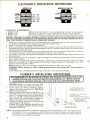
FACTORY AUTHORIZED SERVICE
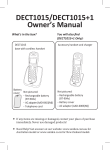
COFFEE BREWERS
MODELS
F-35,
F-20,
F-15
MODELS ABOVE SERIAL NUMBER*
F·35
F·20
F·15
f(J:\666L
~
~
~:~~
LISTED r'pproved
57581
30872
30179
bYe'"''
~
F-S
F-WG
(Stainless)
(Woodgrain)
OPERATING & SERVICE MANUAL
CONTENTS
Electrician's Insrtallation Instructions
Plumber's Installation Instructions
2
2
Initial Operation Instructions
Coffee Brewing Directions
CleaningTips
3
3
3
Trouble Shooting Guide
Component Replacement Instructions
Schematic Wiring Diagrams
Replacement Parts
Warranty
WARNING
DISCARD GLASS DECANTER IF
•
•
•
•
•
CRACKED
SCRATCHED
BOILED DRY
HEATED WHEN EMPTY
USED ON HIGH FLAME OR OPEN
ELECTRIC ELEMENTS.
FAILURE TO DO SO MAY RESULT
IN BODILY INJURY.
10023.0000E
1/94
©
1981 BUNN-O-MATIC CORPORATION
4
8
10
11
Back Cover
E l E CT R I C IAN'S
INS TAL lA T ION
INS T RU CT ION S
MODEL f·35
MODELS f·15 & f·20
1
ELECTRICAL REQUIREMENTS:
• MODELS F35
120/240 volts A.C., 60 hertz, 3 wire, single phase. 20 amp. wiring required.
• MODEL F20
120 volts A.C., 60 hertz, 2 wire, single phase. 20 amp. wiring required.
• MODEL F15
120 volts A.C., 60 hertz, single phase, with two wire grounded cord. 15 amp.
WARNING:
CHASSIS
MUST
BE PROPEBL Y GROUNDED
TO PREVENT
THAT HAVE A GROUNDING LEAD PROVIDED, IF AN ADAPTIVE
VIDED. DO NOT ASSUME A PLUMBING
LINE WILL PROVIDE
POSSIBLE
SHOCK HAZARD.
PLUG MUST BE USED,
SUCH A GROUND.
ON CORD CONNECTED
AN ELECTRICAL
GROUND
MUST
MODELS
BE PRO-
1.
Electrician must provide the outlet, plug to match, and a suitable length of cord or armored cable if
not supplied. (Attached power supply cord provided on Model F15).
2. Power is to be left OFF throughout installation.
3. Before connecting electrically, remove front panel via two screws and be sure the thermostat is
turned all the way to the left (counterclockwise) to the OFF position. Keep in the OFF position until
tank has been filled with water.
4. Electrical service is connected to the termina"1"block at the front of the brewer. Remove front panal via
two screws for access. Strain relief is provided in the rear of the machine.
5. No switch is required. All models should remain connected electrically so heat will be maintained in
the water tank.
6. After connecting service as specified, test the voltage on the field wired side with a voltmeter. Should
be as shown above.
7. With power to brewer OFF, replace front panel. If plumbing connection has been made, the coffee
brewer is now ready for "Initial Operation Instructions."
Refer to page 3. If plumbing is to be done
later, be sure that power is OFF.
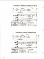
NOTE: Schematic and pictorial wiring diagrams are located on page 10 of manual.
WARNING: Brewer warranty is void if brewer is connected to any voltage other than specified on
nameplate ..
In all installations, the National and-all local electrical codes must be followed.
'.......,)
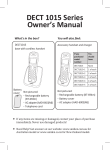
PLUMBER'S
INSTAllATION
INSTRUCTIONS
The equipment is to be installed to comply with the Basic Plumbing Code of the
Building Officials and Code Administrators International, Inc. (BOCA) and the
Food Service Sanitation Manual of the Food and Drug Administration (FDA).
i
CAUTION: Power to brewer must be OFF
before proceeding with plumbing installation.
1. Flush water line before installing
brewer.
Brewer should be connected on Cold Water
Line for best operation.
2. Water pressure should be at least 20 Ibs. For
less than a 25 ft. run, use 1/4" copper tubing
from 1/2" or larger water line_ For more than a
25 ft. run, use 3/8" copper tubing from 1/2" or
larger water line, and provide an adapter fitting for conne.ction to the water strainer.
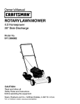
3. Connect incoming water line to the incoming
male fitting on the strainer.
A SHUT OFF VALVE SHOULD BE INSTALLED
ON THE INCOMING WATER LINE IN A CONVENIENT LOCATION.
;
I: 1
18" COPPER TUBING-LEADS
TO
SOLENOID MALE FLARE
FITTING (SUPPLIED BY BOM)
/ /
1/4" FEMALE SAE. FLARE FITTING
(SUPPLIED BY BOM)
/~
='::':':''-'
"
==
", :""'.
U ..".. ··.-;
~
"'~''-
/.
-'
.J·t:,
WATER STRAINER (SUPPLIED BY BOM)
.
// --,-,(SUPPLIED
BY PLUMBER)
COPPER TUBING
,/-
1/4" FEMALE SAE.
~~UPPLIED
FLARE FITTING
BY PLUMBER)
(SUPPLIED
SHuro~
BY PLUMBER)
NOTE: The National Sanitation Foundation requests a provision be made in the incoming water line
for flexibility. This is necessary to allow tilting or moving the brewer for proper cleaning
underneath, etc. A tightly coiled length of copper tubing located ahead of the water strainer
would help comply with this request.
2
~,
J
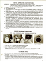
INITIAL
/
\-t
2.
3.
5.
4.
OPERATION
INSTRUCTIONS
IMPORTANT: • Brewer must be level or slightly lower f'n front to siphon properly.
• Electrician's and Plumber's instructions are provided on page 2. These instructions
should be carefully followed before proceeding with initial operation instructions.
1.
• Be sure all electrical and plumbing connections are tight.
NOTE: Be sure thermostat is in OFF position.
Turn power to brewer ON.
Place brewing funnel in proper position for brewing. Place a decanter containing a little water on
center warmer and turn ON-OFF toggle switch to the ON position. This switch must be ON to operate
a brew cycle.
_
Deflect the start switch. This will start a brew cycle and allow water to flow into the tank. Water will
run approximately two minutes before timed cycle ends. Repeat this cycle three additional times;
water should overflow tank into the decanter on center warmer during the fourth cycle.
Turn power to brewer OFF. Remove front panel via two screws. Adjust timer to deliver desired amount
of water. To increase amount of water, increase time of water flow by turning timer dial slightly
clockwise. To decrease amount of water, decrease time of water flow by turning timer dial slightly
counterclockwise.
6. Turn control thermostat knob fully clockwise to the ON position. Turn power to brewer ON and allow
approximately 10 to 20 minutes for water in tank to heat. (F-35 approximately 10 minutes-F-20
approximately 15 minutes-F-15
approximately 20 minutes.) When the water reaches brewing
temperature, the contronhermostat
will click off and the heating noise will stop. On initial heat up,
normal water expansion will occur in the water tank. Water may drip from the funnel due to this expansion, but will not occur thereafter.
7. Turn on-off switch to the ON position. Place empty decanter on center warmer under the funnel and
deflect start switch. Run a partial cycle to remove expanded water from the tank. Now run a full cycle
to check for proper timer setting and to cycle control thermostat.
8. When control thermostat clicks off and heating noise stops, run a cycle to check for proper
temperature setting. With an accurate thermometer, take the temperature of the water at the point
below the funnel opening and at the time when the decanter is about half full. Recommended
temperature of the water is approximately 1950 F. Due to higher altitude locations (5,000 ft. above sea
level) thermostat may have to be readjusted to prevent boiling.
9. If water volume and temperature are correct, replace front panel. Coffee brewer is now ready for brewing coffee.
COFFEE BREWING
FAST,
Drop Bunn filter into funnel.
CLEAN,
CONVENIENT -BUNN®
Pour in fresh coffee.
DIRECTIONS
DISPOSABLE
PAPER FILTERS
Slide funnel into head and brew.
Simply throw out grounds.
1. Place Bunn filter in funnel and add desired amount of coffee.
2. Level the bed of coffee and insert funnel in hood guides.
3. Place empty decanter on center warmer under funnel.
4. Turn on-off toggle switch to the "ON" position, deflect start switch and brew a pot of coffee.
IMPORTANT! Use Bunn Filters for Bunn Coffee Brewers. There is a differ'ence.
CLEANING
TIPS
1. For cleaning all metal surfaces, use any reputable stainless steel cleansing compound.
2. Sprayhead should be checked and cleaned regularly. (At least once a week.) Sprayhead holes must be
kept open.
3. To prevent "LIMING" problems in the water tube and air tube, remove sprayhead and insert deliming
spring all the way into the tank through both tubes. When inserted into tank properly, no mora than
two inches of the spring should be visible. Saw back and forth five or six times. This will keep tubes
open
minute.and clear of lime. In hard water areas this should be done every day; this takes less than a
3
.
aining
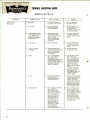
FACTORY AUTHORIZED
SERVICE
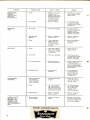
TROUBLE SHOOTING
MODELS
GUIDE
F·35, F·20, F·15
is
WHAT
TO
CHECK
POSSIBLE
REMEDY
1.
7.
and
relay,
relay
andat3.
nections
between
harness
Be
sure
Power.
water
shut
2.
terminal
to
"Electrician's
block.
Refer
Timer.
No
Water.
1.
Solenoid
Loose
On-Off
connection
these
valve.
switch
condoes
4.
6.
5.
not
make
and
Should
hear
clicks
this
would
indicate
a7.depressed, but and water shut off valve.
warmer
switch.
should
heat.
when
micro
switch
arm
sure
contact
(B)
With
Start
If
start
On-Off
switch.
switch
switch
does
8.
at
terminals
and
water
solenoid
valve.
voltage
atsolenoid
off
valve
is
open.
(A)
are
Cord
set
and
plug
Incoming
water
lines
Plug
and
socket
conin
the
ON
position,
Contact
relay
does
points.
not
present
side
points
energize
switch
steps
defective
of
1CAUSE
are
is
the
thru
on
when
depressed,
relay.
clean.
the
solenoid,
5tight.
have
inlet
start
IfOn-Off
Check
paddle
arm
on6.
leased.
If
not,
this
Switch
Relay.
On-Off
Voltage
toggle
continuity.
at
switch.
indicator
contact,
light
and
replace
lamp
center
should
IfBe
voltage
is two
outgoing
side,
replace
not
refer
Ifto
voltage
steps
at
terminals
2break
is
thru
present
is
depressed
and
reline
but
pressure
not
present
is
on
the
SYMPTOM
to
solenoid.
would
indicate
that
the
when
the
start
switch
not
switch.
make
and
break
and
side
check
of
the
for
solenoid
water
valve.
Installation
Instructions"
the
micro
switch
arm
switch
is
released,
timer,
and
terminals
continuity
If
not,
check
.energizes
switch
for
correct
voltage.
refer
paddle
setting
deenergizes
down.
Replace
arm
and
step
iswhen
7.
holding
not
Timer.
restart
relay.
been
Ifline
relay
checked,
replace
contact,
replace
start
on
at
the
pressure
outgoing
start
ato
brew
cycle
4
off.
s
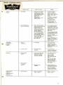
FACTORY
AUTHORIZED
SERVICE
'0551
NO HOT
WATER
Control
Tank
Excessive
and
tank
Lime.
lid
Solenoid
valve
valve
Brewer
must
be
Turn
Water
knob
should
counterflow
STEAMING
(A)
Knob
Not
Siphoning
Setting.
Be
sure
spring
isisinfrom
If
lime
build
up
Insert
deliming
thermostat.
and
air
tube
all
the
back
and
forth
five
are
seat.
cleaned
If vaIve
from
seat
valve
(C)
decrease,
tank
lid
replace
assembly.
control
springholes.
way
(B)in
water
into
Clean
tube
sprayhead
and
saw
replace
is
worn
solenoid
ortank
multilated,
valve.
properly
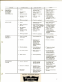
WATER KEEPS
RUNNING
(BREWER WON'T
SHUT OFF
ELECTRICALLY) .
BLE CAUSE
WHAT
TO
CHECK
REMEDY
1. Tank heater
1. Voltage at tank heater
terminals with control
thermostat knob in the
fully clockwise position.
Voltage should be:
Model F35
240 volts A.C.
Models F20 and F15
120 volts A.C.
1.
If correct voltage is
present at the tank
heater terminals and
water in tank is not being
heated, replace tank
heater.
If voltage is not present
at tank heater termina Is,
refer to step 2.
If incorrect voltage
is present on tank
heater terminals, refer
to "Electrician's
Installation Instructions."
2.
2.
2.
(A) If voltage is present
on incoming terminal
(black wire) on the limit
thermostat, but not on the
outgoing terminal, (blue
wire) replace limit
thermostat.
(B) If voltage is present
on both terminals on the
limit thermostat, but not
across tank heater
terminals, replace control
thermostat.
Limit Thermostat or
Control Thermostat.
1.
2.
2. place
1.
Thermostat
lower
inproperly.
front
to
sprayhead
for
approxexcessive,
delime
tank
level
or
slightly
siphon
and
any
particles
1.
Solenoid Valve
With control thermostat
knob in the fully clockwise
position, check the
voltage between the
white (or red) wire on
the tank heater terminal
and the incoming
terminal (black wire)
on the limit thermostat,
then the outgoing (blue
wire) terminal on the
limit thermostat. Voltage
should be: Models
F15 and F20, 120 volts
A.C. Model F35,
240 volts A.C.
(C) If voltage is not
present on the incoming
terminal on the limit
thermostat, refer to "No
Power" Section.
or six times.
clockwise for lower
1.
Refer to "Dripping"
section, step 2.
of
water Ifdoes
not
setting.
temperature
1.
Refer to "Dripping"
section, step 2.
5
-
be
atindicator
least
2of minutes
POSSIBLE
CAUSE
Start
Flow
Clean
Switch.
valve.
flow
valve
of
Timer.
Paddle
arm
on
timer.
Valve.
Flow
REMEDY
TO
CHECK
Timer
dial
3.
1.
start
switch
does
11.
. IfWHAT
1
.times
Solenoid
Clean
solenoid
valve
of
timer
should
be
4.
valve,
2.
at
least
20
PSI.
Adjust
timer
for
atimer
Not
siphoning
replace
timer.
If
paddle
arm
on
Water
pressure
should
be3.
consistency.
Switch
continuity.
Refer
to
"Dripping"
section,
Step
slips
or
doesn't
move,
Low
water
pressure.
at
any
particles
that
3.
higher
setting.
are
irregular,
replaced.
section,
step
1.1.Be
Flow
valve
assembly.
SYMPTOM
with
micro
switch
below
20do
PSI.
or
clock.
arm,
not
contact,
make
then
switch
and
resets.
break
should
the
line
not
reduce
or
interbe
replaced.
Replace
mittently
ifReplace
clog
orifice.
15necessary.
seconds).
partially
any
particles
clog
necessary.
that
orifice.
may
orifices:
partially
clog
water
sure
other
pressure
appliances
to
brewer
in
ifmay
OVERFLOWING
DECANTER
WARMER PLATES
RED HOT-OR
SOLENOID COIL
SMOKING-OR
WATER IN TANK
HEATS EXCESSIVELY
FAST.
1. Receiving decanter
machine.
block.
with
a watch
or clock.
sistency
several
times
(B)
Check
concator
set not
too
high.
section,
steptimer
2.
completely
3.
empty
when
brew
1.
2.
cycle is started.
2.
Timer.
3.
Solenoid valve.
1.
Brewer wired to
wrong voltage.
,
Check
to
see
and
makes
contact
slowly
moves
paddle
arm
onifaround
timer
IfReadjust
times
are
(A)
Timer
dialbrew
indi1. Voltage
Refer
to at"Dripping"
Personnel
operating
timer
terminal
Always
start
Refer
to "Electrician's
for
correct
correct
asempty.
necessary.
voltage
and
decanter
FACTORY AUTHORIZED
6
SERVICE
any particles that may
2.
3.
11.
11.
Installation
Instructions"
cycle
for
(B)
a lower
with
receiving
setting.
section,
step
2.
irregular,
should
be
timer
replaced.
,
r
6 & 7.
properly.
POSSIBLE
CAUSE
Vibration.
If
brewer
is
on
a
Brewer
connected
be
Bunn
Filter
and
coffee
WHAT
REMEDY
CHECK
2.
Water
This
hammer.
not
the
fault
switch
does
not
and
break
when
to
hot
water.
1.
Fi
Iters.
2.
Filters
Bad
Be
sure
harness
should
should
all
coffee
connections
be
4.
3.
4.
1.
2.
3.
in
solenoid
valve.
Warmer-defective.
5.
switch.
Warmer
On-Off
Switch.
5.
Not
siphoning
Filters
should
2.
1.
Adiust
Check
ifconnections
control
Bunn
Filters
thermoin
centered
1
. funnel.
in
funnel
3.
over
90TO
PSI
install
stat
knob
clockwise
Adjust
as
necessary.
Incoming
water
line.
Insta
IIis
should
be
used.
to
"Dripping"
Wrong
Refer
Improper
Tighten
60
High
Improper
water'
cycle
water
to
tightness
water
temperature
sprayhead.
nut
pressure
"Dripping"
vibration.
loading
loading
pressure.
on
temperature.
top
ofismake
of
3.
3.
between
centered
always
be
harness
funnel
and
Missing
Install
for
sprayhead.
sprayhead.
sprayhead.
Voltage
voltage
at
is
warmer
present
Refer
to
"Initial
Operation
plumbing.
not
warmer
terminals,
will
not
butturned
heat,
Number
Water
pressure
of
sprayhead
on
always
sectiOfl,
be
step
used.
1.
are
tight.
to
afunnel.
higher
setting.
section,
section,
step
1.
on
and
off,
replace
A
6-hole
sprayhead
2.
SYMPTOM
counter.
see
that
neither
CYCLE
warmer.
HAS
level.
of
the
brewer.
It
an
air
chamber
to
the
counter,
check
to
be
bed
should
and
coffee
can
usually
be
corrected
copper
bottom
tubing
pan
nor
to
pressure
adjust
regulator
to
50
PSI.
by
plumbing
incoming
rearranging
or
water
adding
some
line.
replace
warmer.
brewer
is
touching
connected
to Cold
terminals.
Should
are being
used.
FACTORY AUTHORIZED
water line.
SERVICE
7
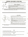
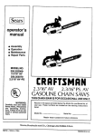
COMPONENT'
REPLACEMENT
INSTRUCTIONS
CAUTION: DISCONNECT COFFEE BREWER FROM POWER SOURCE PRIOR TO REMOVING ANY COM.
PONENTS.
Access to electrical components is gained by removing front access panel.
CONTROL THERMOSTAT
1. To gain access, remove top lid via 4 screws and remove front panel.
2. Remove mounting screws and disconnect wires, remove old thermostat bulb
by pulling firmly upward on the capillary.
TANK
3. On the new thermostat, slide the red capillary grommet to the red mark on the
LID
capillary.
4. Insert the bulb through the hole in the tank lid and press the grommet firmly
and evenly so that the groove in the grommet fits into the tank lid.
NOTE: If water tank is full of water, turn control thermostat knob clockwise to desired setting. Refer to
"Initial Operation Instructions" steps 6, 7 and 8. If water tank is not full of water, turn control
thermostat knob fully counterclockwise until tank is filled.
TANK HEATER
1. To gain acicess, remove top lid via 4 screws.
2.
Remove sprayhead and sprayhead nut from water tube below the
hood.
3.
4.
Loosen compression fitting on air vent tube in hood.
Disconnect leads to tank heater terminals and limit thermostat
terminal.
5.
Remove thermostat bulb from tank lid assembly. Refer to "Control
Thermostat Replacement" step 2 above. Take care not to damage
thermostat capillary or bulb.
6.
Remove 8 nuts holding tank lid to tank and lift out tank lid.
7.
Remove 2 nuts holding tank heater to tank lid and remove tank
heater.
8. When replacing tank heater, be sure to use new copper washers.
Nuts should be securely tightened to assure water proof seal.
NOTE: When replacing thermostat bulb in tank lid assembly, refer to "Control Thermostat Replacement"
steps 3 and 4 above.
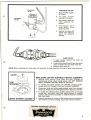
TIMER
1. To gain access, remove front panel.
2.
3.
Disconnect plug and socket connector and disconnect the 2 leads on the solenoid terminals.
Disconnect timer from bracket via 2 screws and remove.
RELAY
1. To gain access, remove front panel.
2.
3.
8
Disconnect plug and socket connector from harness plug and socket connector from timer.
Disconnect relay from bracket via 2 screws and remove.
I •
~~\P~3
which "-hold solenoid
II
l ,--.
. \\ II It'valve
Disconnect
terfleads
I are
chassis
tofrom
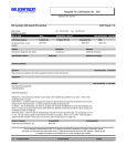
SOLENOID
VALVE
Remove
2 screws
(D)
Shut
(B&C)
off
water
supply
(A)
To
gain
access
solenoid
valve.
SOLENOID
~ solenoid
II
1.bracket.
2.
from
to brewer.
~,
3.
remove front panel.
1.
2.
NOTE: When installing
3.
new flow valve into solenoid, be sure
FLOW VALVE
To gain access remove top cover via
screw(s) on top.
Loosen flare nuts (B and C) and free short
piece of water line from flow valve (D).
Remove flow valve (D).
direction of arrow is away from solenoid.
REPLACING ON-OFF SURFACE HEATER ELEMENTS
1. Remove lower warmer cover plate and heat spreader by
unscrewing center sheet metal screw. DO NOT REMOVE
SMALL SCREWS HOLDING EDGE OF SAUCER.
LOWER WARMER ASSEMBLY
2. To remove the lower warmer, lift element, bringing downcurved ends out through curved slot in saucer assembly.
3. Disconnect blue and white spade-clipped wires from element
terminals. These are interchangeable when replacing element.
4. To install new element, bring spade-clipped wires up through
curved slot, reconnect them, and place element in original
position. Be sure heat spreader is replaced between element
and cover plate.
5. Warmer elements on the top of the brewer are not as shown at
left. Remove 3 screws holding saucer and remove element.
FACTORY AUTHORIZED SERVICE
9
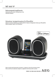
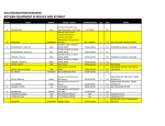
SCHEMATIC
WIRING
L1
DIAGRAM
GREEN
SW. &
THERMOSTAT
LIMIT
F151320W
F20 1800W
BLK
TH~~::;.:
...:~
WHI
~
F15 & 20
f--'VVV'
BLK
TANK HEATER
N
=!.
50W
'KEEP WARM' HEATER
BAN
100W
P3
P2
--{}-'VV'.
TOP REAR WARMER
BLU
P1
100W
-u-~
WHI
TOP FRONT WARMER
r ....~···~
BLK
BLU
LOWER WARMER
1..L1
.u-
--«
·
2 WIRE
P1
BLU
lit
120 VOLTS A C
130W
~
·.. P3
<,
BLU
BLK
P1, P2, & P3 ARE PINS OF
A POLARIZED THREE·PIN
.. CONNECTOR.
SINGLE PHASE
60 HZ
SCHEMATIC
WHI ~~ WHI
WIRING
DIAGRAM
F35
GREEN
L1
SW. &
THERMOSTAT
LIMIT
3500W
BLK
T~£~:.;:::.:.~4
WHI
~
BLK
f-J'A/'V
RED
TANK HEATER
50W
'KEEP WARM' HEATER
BRN
RED
100W
P3
P2
--{}-'VV'.
WH
TOP REAR WARMER
WH
BLU
P1
----.r- ~
WOW
WHI
TOP FRONT WARMER
WH
BLK
---lliJ!.
~
130W
WH
LOWER WARMER
BLK 1..L 1
~~
120/240 VOLTS A C
3 WIRE
SINGLE PHASE
60HZ
10
L2
N
~
BLK
·
«
·..P3
P1
BLU
<,
BLU
BLK
P1, P2, & P3 ARE PINS OF
A POLARIZED THREE·PIN
CONNECTOR.
WHI ~~
WHI
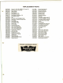
REPLACEMENt PARTS
01637.0000
00658.0000
00831.0000
Cordset, 5',16/3, HSJO, NEMA 5-15P (model 15)
Decal, Decanter & Funnel Safety
Decal, Electrical
01188.0000
20528.1175
00445.0000
20526.0175
01155.0000
04002.0000
Deliming Spring
Flow Regulator (.175)
Flow Regulator Adapter
Flow Regulator Diaphragm (.175)
Flow Regulator Gasket
Foot
02028.0000
02028.0002
20247.0000
Funnel Assy, Complete W/Black Handle
Funnel Assy, Complete W/Orange Handle
Funnel Basket
20244.0000
Funnel Handle, Black
20244.0001
01031.0000
20245.0000
Funnel Handle, Orange
Funnel Tip Kit
Funnel, Stainless
02074.0000
Funnel, Wide Pouchpack
00460.0000
01201.0000
01540.0000
Tank Lid Inlet Fitting Assy
Tank Lid IInlet Fitting Gasket
Tank Lid IInlet Fitting Washer
04635.0000
04680.0002
Leg, Chrome (3" Set of 2)
Limit Thermostat
04646.0000
04645.0000
10940.1000
01085.0000
01079.0000
01066.0000
01101.0000
Momentary Switch
On/Off Switch, Lighted
Shipping Carton, Complete
Solenoid Valve
Solenoid Valve Base
Solenoid Valve Bonnet Wrench
Solenoid Valve Coil
FACTORY
I~
I
i
AUTHORIZED
01111.0000
01075.0000
05515.0000
05551.0000
01082.0000
02795.0000
00736.0000
05518.0000
04236.0000
04636.0000
04637.0000
04626.0000
05541.0000
04221.0000
Solenoid Valve Repair Kit
Sprayhead Fitting Nut
Sprayhead Tube Gasket
Sprayhead Tube Kit
Sprayhead, 6-Hole
Sprayhead, Plastic
Sprayhead, Pouch pack
Syphon Hub
Tank Heater (1320W) (model 15)
Tank Heater (1800W) (model 20)
Tank Heater (3500W) (model 35)
Tank Keep Warm Heater (50W)
Tank Lid
Tank Lid Gasket
04131.0000
01106.0000
07038.0000
07073.0000
04314.0001
02235.0000
Tank W/Keep Warm Heater Assy
Terminal Block (model 15&20)
Terminal Block (model 35)
Thermostat Grommet
Thermostat
Timer
03695.0000
03625.0000
03655.0000
Warmer Assy 130W (Lower)
Warmer Assy WOW (Upper)
Warmer Dish, Porcelain
01227.0000
01142.0000
05212.0000
01183.0000
Warmer Element (1 OOW)
Warmer Element (130W)
Warmer Retainer Plate
Water Strainer
01839.0000
01841.0000
Wiring Harness (model 15&20)
Wiring Harness (model 35)
SERVICE
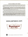
BUNN-O-MATIC
COMMERCIAL
PRODUCT
WARRANTY
_
Bunn-O-Matic Corp. (UBunn") warrants the equipment manufactured by it to be commercially free from defects in material
and workmanship existing atthe time of manufacture and appearing within one year from the date of installation. This warranty
does not apply to any equipment, component or part that was not manufactured by Bunn or that, in Bunn's judgement, has
been affected by misuse, neglect, alteration, improper installation or operation, improper maintenance or repair, damage or
casualty.
THE FOREGOING WARRANTY IS EXCLUSIVE AND IS IN LIEU OF ANY OTHER WARRANTY, WRITTEN OR ORAL,
EXPRESS OR IMPLIED, INCLUOING, BUT NOT LIMITED TO, ANY IMPLIED WARRANTY OF EITHER MERCHANTABILITY OR
FITNESS FOR A PARTICULAR PURPOSE. The agents, dealers or employees of Bunn are not authorized to make modifications
to this warranty or to make additional warranties that are binding on Bunn. Accordingly,
whether oral or written, do not constitute warranties and should not be relied upon.
statements
by such individuals,
The Buyer shall give Bunn prompt notice of any claim to be made under this warranty by telephone at (217) 529-6601
or by writing to Post Office Box 3227, Springfield, Illinois, 62708-3227. If requested by Bunn, the Buyer shall ship the defective
equipment prepaid to an authorize,.d Bunn service location. If Bunn determines, in its sole discretion, that the equipment does
not conform to the warranty, Bunn- shall repair the equipment with no charge for parts during the one year warranty period
and no charge for labor by a Bunn Authorized Service Representative during the one year warranty period. If Bunn determines
that repair is not feasible, Buim shall, at its sole option, replace the equipment or refund the purchase price for the equipment.
THE BUYER'S REMEDY AGAINST BUNN FOR THE BREACH OF ANY OBLIGATION ARISING OUT OF THE SALE OF THIS
EQUIPMENT, WHETHER DERIVED FROM WARRANTY OR OTHERWISE, SHALL BE LIMITED, AS SPECIFIED HEREIN, TO
REPAIR OR, AT BUNN'S SOLE OPTION, REPLACEMENT OR REFUND. Bunn shall not be liable for any other damage or loss,
including, but not limited to, lost profits, lost sales, loss of use of equipment, claims of Buyer's customers, cost of capital, cost
of down time, cost of substitute equipment, facilities or services, or any other special, incidental or consequential damages.
www.pamasco.com
r~~~--c
fPAMASCC4D
Seudu &tta
*
Printed on recycled paper. Consider the environment.
Please recycle.
""-