1
.
and
f
\ .,
...'
YARD
-~.;1AN co.
P. C. BOX 36940
CLE'JELAt'JD, OHIO
1410 West Ganson Street
PRINTED.IN
U..S.A.
-Jackson,
~ichigan
44136
49202
0611-724A
2.
3.
7.
9.
tI, i'
,
b.,fj;,
.;,
RULES FO.~~SAFE OPERATION
.;
~~
Your SNOW THROWER is a precision piece of snow throwing equipment. Engineering skill and experience have been combined to
provide the ultimate in safety and efficiency. As with any type of power equipment, carelessnessor error on the part of the operator
can result in injury. EXERCISE EXTREME CAUTION AT ALL TIMES.
1.. READ THE OWNER'S MANUAL CAREFULLY.
-
,.
Know the controls to operate your SNOW THROWER properly and how
to quickly stop th~ :-unit.
.,
"
:"
'~
BEFORE STARTING ENGINE, disengage all clutches and shift unit into neutral. Keep hands, feet and clothing away from
power driven parts. :'
::
DISENGAGE POWER AND STOP MOTOR before cleaning discharge, removing obstacles, making adjustments, or when
leaving operating position.
,," .
.: ,:~,.~.~".4.
NEVER
DIRECT
DISCHARGE
AT BYST~N~ER~
snow.
in front
of machine -debris
may be hidden
in the
:-~,;;,::;:
5. KEEP CHILDREN
AND PETS a safe distance away.
6. DO NOT ALLOW
CHILDREN
ADJUST SCOOP HEIGHT
8. EXERCISE
HANDLE
or allow anyone
CAUTION
GASOLINE
TO OPERATE
MACHINE
or allow adults to operate machine without
to clear gravel or crushed rock surface.
to avoid slipping or falling, especially when operating
WITH CARE -it
in reverse.
is highly flammable.
a.
Use approved gasoline container.
b.
Never add gasoline to a running mo~~~.F!" tank outdoors and wipe up spilled gasoline.
c.
Replace gasoline cap securely.
d.
Open doors if motor is running indoors -exhaust fumes are dangerous.
10. USE A GROUNDED
;",
THREE-WIRE
PLUG-IN for all units equipped with electric starting kits.
"":
11. KEEP UNIT IN GOOD OPERATING
", ..';
.;,;.."
CONDITION
and keep safety devices in place.
2
proper instruction.
"'~-""
-,
., ,-~
..,.
-., ~,.
~ ...:.~~,:,
,
tE';'
IFOR
l_SUGGESTIONS
i;J;~:"';,
i.
..';
~:';
':.;~,
GJNERAL
SNOW
" t.'~"
!~
~.FREE
OPERATION
~I~;.;".;,~i:~~.':'.,-.,
,,~~~~~;
~,~~
~ ;::' ~:~c:;::,~".:
,~-- ~-,
..~~,--' :;,.,...'
,:',:";'.';-;,
,-.: ;1t5::~::.~;~:,t..:~"-,,!:I~,~';~~t
I..THRQWJNG
I.fi;r.:.";;,~~..:,
'::J..~o.i:.:..-""C,'
IfAIW'Y' keep
~re~t~
, ,;j:~i, .'
co.'
~
;-"(.;.,.,
...
'c~i!i!;:~:,J!:
~
2.~~ Always start engine with machine on level. Sl!~~.'."wi,t~",master
clutch disengaged. A~er starting, let engine warm up several
::r ~inutes at slow speed be:ore starting to re~o~~~~~t"..~r~~,~~~~e..i~~ored
indo~rs, let engine and machine adjust to outdoor
.-;~ temperatures before starting to thr~w snow!';::'::,b~~~1'!f!-' ..t*~~t:~';;:~;;i:;;;(:':~.
...'
:~
.".
:.'
...' '~r..~..
:-'-"
When in deep heavy snow, shift to slowest speed, and start at the edge of area to be cleared, discharging snow to the outside.
i'J
:C:':, -.'i:
:
4.~
,.".",-'..",-"i',.'
best r~i~~~,'.,!~~'::.,.1:f,.
"c,
When throwing
*
snow, run machine at full throttl;'f'~r
~,~.-\,,'
3.~
lO"',.:.~\'..7~}.:>!.:;';,
,.
.:.,;;.
...,;:;..,.,'(.!Jif
5'f:~ Always run engine a fe:-vminu~es b:fore
;:,-
storing, to dry moiSture that Collects inside of engine from blowing snow.
,~~~;?':E
:
,.:;,0:,,~~ ,o--
:~{
Your
~;:
:~;
MAINTENANCE
e.;j
f(,.iil; o'o~:,,";.""~:';!::
SNOW THROWE'R
I .';C:"
like all machines with ~oving
~
-,
"0'::-1
;;".;:,-,-
",:!:"
p~rts, must receive care and maintenance.
~.
The following
tips, if used, will
contribute many trouble-free hours to your machine.
Check engine oil level frequently, or every 5 hours' of use. When changing oil, make sure dirt and debris is cleaned from oil
drainareabeforerem~vingoilplug.'
':
...'; ..,:'c'.i
I,.
f'
..'C.:
Keep fan and auger housingscie~ri.
(,
,"'~:,
'..,
i,C;. t:.,., ~ i.. :C.:~
.-"'r
':' ::' ~!
'
;
Check all nuts, bolts and screws occasio~al!y for tightness to be sure machine is in good operating condition.
.'
.j.
4. Should excessive vibration develop, check,your fan and fan shaft immediately. Do not operate the machine with a bent fan or
shaft.
5.
..'
.:.
':"""~~l.
~""
'
The machine is pre-lubricated at the factory. However, lubrication with each usagewill prolong life of working parts.
If you are going to store your SNOW TH ROWER for any length of time (30 days or longer) it is important that the following
..-;'" ".
steps be taken ..."
, ...;
,., '" "',...".'
, .
,
..fC
.-
Drain the gas tank and carburetor. Start the engine and run it until out of gas.
Gasolin:e..'e~in the engine willlea~e gum deposits in the carburetor and gas tank.
b.
Clean engine
of all foreign matter.'.
..:
.'
c.
Lubricate cylinder by removing the sparkplug and pouring one ounce of clean
lubricating oil through the sparkplug hole into the cylinder. Crank engine slowly to
spread oil and replace sparkplug.
Should unusual vibration develop in transmission, remove rubber panel in rear cover and check rubber drive disc condition. For
reference see page 11.
The belt tension is adjustable. The tensioning of belt should be checked every 5-10 hours of operation. Refer to adjustments
section for re-setting.
To prevent recoil freezing, when snow thrower is to be stored outside or in sub-freezing shelter, pull recoil rope out 6" to 12"
and tie knot in rope or fasten handle to keep rope from re-winding. This procedure will set inner parts in position for starting.
Just as your automobile net:ds professional mechanical maintenance from time to time, so does your air-cooled engine. A yearly
tune-up and check by a qualified service center is recommended to avoid breakdowns and unnecessarydelays during the snow
throwing season.
MAINTENAN
3.
2;
6.
10.
9.
8.
7.
3
.,.
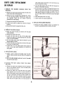
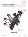
UNPACKING AND SET-UP
1. Be sure carton is right side UP. cut end panels out and
fold flat on floor. Remove inner pack and roll unit out
of carton.2.
Assemble right and left handle tubes to the unit with
bolts and flat washers. Do not tighten.
3. Assemble handle panel assembly to the under side of
right and left handle tubes and secure with four slotted
hex head bolts and lock nuts. Tighten all bolts on the
handle assembly. Place handle grips over ends of the
handle tubes.
4. Assemble chute adjustment shaft through hole in the
handle panel and into uni";'ersal.joint located on lef!
hand side of the frame. Align hole in universal joint with
the hole in chute adjustment shaft and drive spring pin
through the holes.
5. Attach master cl~tch rod adjusting link into the bottom
hole
-,
;"'*-""""',"'""
of
master clutch
control
located
on .the. handle"panel'andi~""t(.."'-"';)"."';"
':
.'J.
-..'
..Move
I
..
.1ever forward to. thf! end o.f"the not6h To. adjust:,. remove
cotter pin from clutch lever adjustment link and thread
op or down until the link is the full hole short of reaching the hole in tl)e clutch lever. Move .clutch lever back
slightly
to. rec9nnect link.. Replace Go.tter pin and spread.
6. Remove rubber shift lever panel from parts package and
slip over end of shifting lever. I nsert shifting lever into
back of rear cover and slip small shifting rod through
bushing in end of lever. Secure shift lever to mounting
bracket with bolt, washer, bushing, and nut. Assemble
t.hreaded rod into end of shift lever through handle
panel, locking rod in position with nut. Assemble plastic
knob onto shift lever rod. Snap rubber shift lever panel
into rear frame cover holes. Refer to Page 7 to make
adjustment
of shift lever panel no~ches.
4
,.,
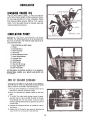
BEFORE STARTING ENGINE
!
1. Fill the fuel tank. with fresh winter blend regular gasoline. DO NOT MIX OIL WITH GASOLINE.
Make
certain the fuel shut-off valve under the gas tank is
turned on.
2. Place machine on a level surface. Remove oil fill cap and
fill crankcase with good quality detergent oil.
Use MS classification SAE 5W-20 oil for operation
below 400 F. Use MS classification SAE 30 oil for
operation
3. During
above 400 F.
initial
"Break-in"
period,
the
oil
should
be
checked often.
4. Change oil after first two (2) hours of operation and
check oil level every five (5) operating hours or each
time machine is used.
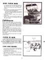
STARTING ENGINE
Shift the master clutch control to the Neutral position.
Move the choke lever to full choke position. Move speed
control lever to run position. Start the engine by pulling
rapidly on the recoil starter rope. As the engine starts and
begins to warm up, gradually return the choke lever to the
"No Choke" position.
NOTE: Temperatures 100 F. and below IJse "Primer."
Push primer button in and hold, pull engine slowly over
compression once and release primer button. DO NOT
ATTEMPT TO START THE ENGINE WITH PRIMER
BUTTON HELD IN. (Do not use primer with 110 volt
electric starter).
If the engine should fail to start, refer to your engine
Instruction Manual.
STOPPING THE ENGINE
To stop the engine move the speed corittollever to the stop
positi9n or close the fuel stlut-off valye under the" gasoline
~: tank." The sparkplugOwire may ~iso be ~emoved to pr~vent 0 0J';I.~
acci.dental sta"fltiflQ-'Whil~unattended. AI~ays oru~'~ng1*e"a ..,
.few inin~tes" befere StoriRg to diy o..r,oisture that corrects o':.'.
.inside ofen.gine from blowing.snow 0
BEFORE
SNOW
.
.THROWING
.
1. Try your Snow Thrower machine in a large open space
with engine throttle in slow position. Learn to start, stop
and back-up during this trial run.
2. In rough areas, lower the adjustable skids.
3. Remove stones, wire, cans, boards, bones or other solid
objects from area to be cleared:
4. Always
run
engine
a few
minutes
out-doors
before
throwing snow, to adjust engine and machine to outside
air temperature.
5
,'
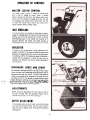
OPERATION OF CONTROLS
MASTER CLUTCH CONTROL
The master Clutch control is located on handle panel
and is used to engage all power. Select a forward
speed or reverse with shift lever, then release master clutch
control and push forward to engage drive disc, fan, reel.
To disengage, pull master clutch control back and lock
in notch. The master clutch control must always be in
neutral position before starting engine.
FREE WHEELING
The wheel clutches are located on wheels and are used to
engage or disengagepower to wheels. To free the wheels for
pushing, pullout on the knob and turn to lock. To provide
self-propelling power to the wheels turn clutches in the
opposite direction and relea~. The wheel clutches are
spring-loaded, move unit until the clutches lock to wheels.
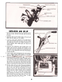
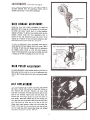
DEFLECTOR
The deflector may be positioned in either a vertical or a 450
position in relation to the spout as needed for proper snow
deflection by loo~ning the two wing nuts on both sides of
the deflector. NOTE. For shipping purposes the deflector is
lowered off the hinging pin. Loosen the wing nuts and
reposition the deflector over the pin before operating the
Snow Thrower.
DISCHARGE CHUTE AND SPOUT
"
..To'.rotate
tlie
."
diScharge
.;~,.., '"
chute
to the
",
right
';~
or left,
.
release
chute lock lever. then rotate with chute adjustment shaft to
desired position and lock. NOTE: The spout and deflector
rotates. automatically wh~n rotating the discharge chute to
t.he right and lett. If it is desired to change position of the
.('j spout;.I!ft spOut look'iever on'..the right hand.si~~ of~riit!
;! o,o,.~..
,
0: °
...ri
hold-..while rotating thespout.8IRele~e'~~nd
~ turn spout sl.ightly .until it "locks'into-positiori',.'.
.'
"
.
AD~USTM'ENTS
NOTE: Make all adjustments with 'the engine turned off
and wire removed from the sparkplug.
(Fasten wire to
cylinder head at least 1" away from sparkplug.)
DEPTH ADJUSTMENT
The adjustable skids may be set lower to prevent picking up
loose stones and foreign material. Also they can be raised to
allow the reel to slightly touch the ground for additional
pulling.power.
6
REPLACING SAFETY SHEAR BOLT
If the intake snow reel should jam causing the safety shear
bolt to shear, it may be replaced with a new bolt, furnished
in the parts bag, after removing
the broken pieces in the
shaft. NOTE: Always align the hole in the reel shaft and the
sprocket shaft before driving out the broken bolt.
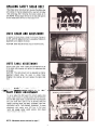
CHUTE CHAIN AND ADJUSTMENT
To tighten the chute chain, rotate the chute all the way to
the left, until the adjustment bolt is accessible. Tighten the
adjustment nut to tighten the chain.
CAUTION: Chain should be kept snug on chute housing.
CHUTE CABLE ADJUSTMENT
Remove cable roller cover, loosen the locking bolt on top
of the cable roller bracket and tighten the adjustment bolt
on the side.
CAUTION: The cable should not be adjusted too tightly,
adjustment should allow the spout to rotate freely.
R.e~ighten th~ locking bolt and replace the cable r~ller
cover.
-..:\."~,\,-"..'
.~.4n:",;.,_:
~"T"-:;iNii~
!
"...,,'.";",
",~"""'~H.I
liST"iE~NT
"", ..~~.
:~
To set .or adjust .the shift panel for correct speeds, place
master clutch control in neutral position and the shift lever
into the fifth speed notch. loosen ~he'two mounting bolts
and push sh.ift lever. right as far as ~llowed, hold,. and
tighten mounting bolts. DO NOT ATTEMPT THIS ADJUSTMENT WITH THE ENGINE RUNNING.
To check
adjustment, start engine, move shift lever to first speed
notch and engage master clutch
move forward .very slowly.
control.
Unit
should
NOTE: Adjustment section continued on page 12.
7
~
r oj
/'
~
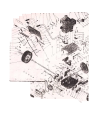
See pages10 and 11 for parts list.
9
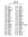
PARTS LIST
MODEL 7100-1
Your SNOW THROWER is right hand (R.H.) or left hand (L.H.) as you operate mad1ine.
REF.
PART
NO.
NO.
DESCRIPTIDN
1
2
3
4
5
6
7
8
9
10
11
12
13
14
15
16
17
18
19
20
21
22
23
24
25
26
27
28
1539-80
1658-29-40
41256
2119-49
3616-516
1538-30
40070
2643-51-40
1710-50-40
4712-99
1!.Q9-1 39
1616-459
4712-98
40890
40149
40148
3-79
3609-433
41994
1605-582
1683-92
40035
21989
1683-93
3153-36
1008
1642-112
1705-39
29
41-028
Nut
30
31
J2
JJ
34
35
36
37
38
39
40
41
42
43
44
45
46
47
48
49
50
51
52
53
3709-33
2616-461
41226
1674-47-40
42200
2705-40
1509-34
40892
1657-58
1552-9
1683-94
42342
2155-26
1509-17
1657-67
40153
1643-52-41
1548-14
1642-114
3609-442-41
40052
1540-137
1652-122
3110-67-41
Panel
54
40864.
55
56
57
58
59
60
61
62
1657-71
2632-183
1646-23
22222
1657-61
1548-20
42373
42180
1606-144
3765-5
41182
..'
,JII9-60' .
..1513-115
1509-136.
'.
69
70
71
72
73
74
75
76
77
78
79
80
81
R2
1543-46
41299
1543-57
1652.115
1509-15
1650-50
2638-5j
40157
2632-180
40790
1680-75
2632-178
42011
",no.':'7
Nut
-Push
Roller
1/2
-Crank
Washer
-SA.E.
Assembly
Dacal
Nut
-Hex
84
85
86
87
88
89
90
91
92
93
94
95
96
97
98
9!!
1018
3626-91
1651-45
3675-20
153986
3622-115
2622-121-40
40050
2635-74
40735
1654-32
2638-52
1652-92
2622.118
1509-69
1650,51
1540-138
Crank
Bolt
Knob
-Flanged
-"T"
Panel
Lock
1/4-20
Grip
-Handle
Handle
-L.H.
Bolt
-Hex
Head
Decal
Handle
ESLOK
Whizlock
1/4-20
x 1/2
1/4-20
x
x I"
Grade
Slotted
1.1/2
-Operations
-R.H.
Bolt
-Hex
Washer
Head
-Lock
5/16-18
Spring
Washer
-Standan!
Bolt
-Hex
Head
Bracket
-Shift
Spring
Dacal
Type
5
5/16
Wrought
5/16
5/16-18
x 3/4
Lever
Mount
-Extension
-Name
Plat8
Rod-Clutch
Pin -Cotter
Link
Rod
1/8
-Rod
-Clutch
Asembly
W-
xl"
Adjustment
Handle
-Handle
-SAE
3/8
Spring
Lever
Panel
-Compression
-Clutch
-Hex
Lock
5/16-24
-Shifting
Decal
Knob
-Shifting
-Shifting
Cap
Panel
-Chute
Spring
Lever
Bolt
Lock
-Extension
-Chute
Lock
-Hex
Head
1/4-20
x 3/4
W--SA.E.1/4
Bushing
-Step
Washer-Wave
Rod
-Shift
Lever
Nut
-Hex
Lock
Assembly
Bolt
-Hex
Extension
3/8-16
-Shifting
Head
ESLOK
Lever
5/16-18
xl"
8ushing
-Spacer
Nut -Hex
Lock
12-Wavl
Assembly
Pin -Spring
w/Lock
xl"
-Knob
1/8
Spring
-Compression
Brecket
-Wheel
Pin -Spring
Washer
-Flat
Bushing
Pin
Lock
Steel
51/64
-Flanged
Asembly
W-
x 1-1/4
x 1/32T.
Wheel
-Wheel
Complete
-"latSteeI51/84~I-1/4
Key
-Woodruff
Universal
Joint
Bushing-Hex
Pin-Spring
Nut -Hex
Lock
5/16-18
Nut
Lock
IEsn8
-Hex
Plate
-Chute
No.
Sprocket
10-24)
Cover.
Strap
-Scoop
Mount
LH.
Nut -Hex
Lock
IEsn8
3/4-161
'~Iy
-Sprock.t6Sh8ft
Bolt
PART
NO.
100
101
102
103
104
105
106
107
lOB
1657-65
1513-113
1513-125
2118-58
1539-90
3622-122
3765-6
2168-55
1654-35
100
110
111
112
113
114
115
3150.17
41362
3120-70
1509-126
40156
Busning -Step
Bolt-Shoulder
1/4-20
Bolt -Shoulder 1/4.20
Assembly -Chein Cover
Nut -Speed Grip 1/4-20
Cover -Chain (Inside)
Strap -Scoop Mount R.H.
Assembly -Frame
Chain -Real w/Conn. Linit
No. 40.110
Pitches
Sea Page
Sea Page
Assembly -Chute Frame DiE(Completet
Bushing -Oil Filled
Assembly -Ceble Pulley
Bolt -He.
Heed 1/4-20.112 Grede 5
Washer-SA.E.5/16
116
117
20263
60051
Cable-SteaII/16Dia..96"
Bracket-CableT;ghtener
lIB
119
120
121
122
123
124
125
126
127
128
129
130
131
132
133
134
135
136
137
138
139
140
141
142
143
144
145
146
147
148
149
150
151
20110
40108
2169-31
40152
1657-64
1683-91
1625-31
1169-32
41767
2609-440
1642-111
41374
2130-11
1609-542
40115
1513-36
2200-57
2659-22
1509-134
1657-40
22455
1657-41
1646-20
40794
1542-8
1509-105
4622-120
1616-458
42235
3556-14
20102
40085
3213-7
4;0100,. ,
Roller -Cable
Bushing-Cable Roller
Assembly -Arm (Clutch Linkege)
Bolt -Hex Head 5/18-18.1-1/2
8ushing -Step
Rod -Idler Link
Link -Rod -Connecting
Assembly -Idler Arm
Pin-Cotter3/32.3/4
Brecket -Idler Mount
Spring -Extension
A_mbly -Pulley Idler
A_mbly -Engine Be.
Bracket -Support (Belt Covert
Nut-Speed (U-Type) 1/4-20
Bolt -Flanged Whizlock 1/4-20.5/8
Engine -7 H.P. Tecumseh
Guide -Belt Restrictor
Bolt -Hex Head 5/16-24. 1/2
Bust.ing -Spacer
Pulley -Engine
Bushing -Spacer
Key -Pulley
Washer -Standard Wrought
Washer -Lock 3/8 Spring Type
Bolt -He.
Heed 3/8-24.1/2
Cover -Pulley & Belt
Decal -Belt Replacement
Decal -SPOUt Relea.
Deflector -Discharge
Nut -Wing
Washer -Cable Clamp
A_mbly-Spoutw/Flange
Bolt-;CarriageShortSQ.Neck
.5/16-18
x1
152
153
154
155
156
157
158
159
.'60..
1704-8
1511-44
1529-30
40496
3102-179
1513-122
1540-145
1209-2
16~
Shoe -Retainer
Scr_-Slotted
He. Head No.6 x 3/8
Bolt -Carriage 1/4-20 .1/2
Screw-He.Head5/16xl-1/2Type8
Assembly -81cwer Housing & Chute
Scr- -Self Tapping No. 10-32 x 3/4
WashOr-StanderdWrought
Assembly -Chute Chain
.Chainw/Conn.Link'~o.41x32Pltches
x 1/16T.
Bushing
-Spacer
L.H.
Shaft
-Wheel
Axle
ff. .i;",
.
161
40110
-162 .3622-123
~
..163
..~64
DESCRIPTION
..
.
.:;;.:.'.'.."
,
-.",..
"",,--~""
,~,:
9c1lt-ChalnConnecting
.Cov..-CableRoller.Brecket
'-'40495
.:219'7'S.. -..~",-~.;;;
.-A~~y8-Fa~':- Slotted HexH~
:.
.
.
~
5/10-" 1~-~r~--,
...'~."""""'-"-
-..J"
80lt
-!:lex
Head 3/~16
x 1"
Washer
Grade -Flanged
5 ESLOK
Retainer
w/Oil
Bushing
-Spherical
Washer
20
-Flanged
Sprocket
Bolt
-Hex
Whiz1ock
Shaft
165
156
167
Groove
T.
Head
...
5/16-18
x 5/8
-Offset
Pin-Spring
Arm
-Lever
(Clutch
Shaft
-Intermediate.
Key
8,,11
-Woodruff
-Yex
Head
Washer
Pulley
Belt
Disc
Rodl
3/16
(Self
x 5/8
Tapping)
x 3/4
-Lock
-"V"
-"V"
Spring
Special
4L
-Friction
Type
8"
Drive
Grip
1/4-20
Frame
Cover
-Shift
Pin -Spring
Lever
Panel
5/16
x 2"
Gear
-Spur
38 T.
Ring
Chain
-Retaining
-w/Conn.
3/4
Link
No.
41
x 36
Pitches
15T.
Bushing
-Spherical
3/4
Cover-Gear tLower)
.Bolt
-Hex
Head
1/4-20
Ring
-Retaining
Washer
-Flat
1/4
Special
Nut -Speed
Cover
-Rear
Sprocketw/Hub
42194
.42195
42193
Retainer
3/4
Shon
1/4.20
x 1/2
(External)
-20
,
MM
Bushing
-Spherical
Bolt
-Hex
Head
RinD
-ReYining
1/4-20
83
1/2
-Chuta
-Handla
REF.
NO.
x 1-3/4
IExternal111/16
Steel
23132
x 1.1/4
x 1/32T.
10
168
1509-117
169
170
, 171
1538-22
3609.438
42364.
172
173
174
175
176
177
178
179
180
181
182
185
186
IB7
IB8
189
190
191
192
40160
3609-439
40160
2713-10
1119-46
1657-83
1657.70
2616-514
2212.11
2121.17
1652-117
1642.110
1650-48
1540-118
1626-76
1657-60
1169-30
1513-112
1540-141
193
194
195
2135-53-41
40027
40883
Nut ~ He. LoCk No. 8-32
Washer -Flat Steel No.8
Scr- -Slotted Round Head
No- 8-32 x 1-3/4
Bolt -Hex Head 3/8-16.1-114
Grad' 5.
Nut -Hex Flanged Whizlock
Bracket
-Scoop 3/8
Mountlng
Nut -He..Lock
Esna R.H.
Bolt -Carriage 5/16-18.3/4
Bracket -Scoop Mounting L.H.
Bolt -Carriage 5/16-18 x 3/4
Skid -Scoop
Assembly -Real Shaft & Pla,e
Bushing -Spacer
Bushing -Spacer
Decal -Caution
Assembly -Scoop
Assembly -Reel Sprocket
Bush;ng -Scoop End 7/8. 1 .3/4
Spring -E.tension
Ring -Retaining (E.ternal 1/2)
Washer-FlatSteeI17/32.1-1/4.1/16T.
Pulley -Chain Idler
8ushing -Chain Idler
Assembly -Arm (Chain Idler)
Bolt-Shear
Washer -Flat Steel (As Needed)
57/64xl.1/4.1/32T.
Assembl~- Reel w/Bushings
Bushing -Oilite
Washer -Flat Steel (As N..dedl
57/64.1-114.~/32T-
~
.'..
~.
~.
:
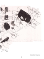
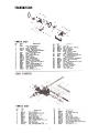
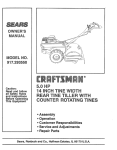
TRANSMISSION
S
'/"
7
8,9
/,
~.
., '0
,
~
I
"
0&0., --
: o;..~~
)0'
~
~/
) '~
.~'l"~/20
'...~
~-.
.,
.."
».-
..
f
,
/
23
~.';'
2K
22-
.
~
/ / ;
~'",
..I
PARTS LIST
REF.
NO.
1
PART
NO.
1654-31
2
3
4
1624-192
1652.114
1149-5
5
6
7
B
9
10
11
12
13
14
15
16
17
1B
19
20
42342
1008
1646-24
2638-51
1624-191
1632-177
2111.107
1538-30
101B
1657-60
40148
42373
3150-1
2676-9
1629-15
1509-00
DESCRIPTIDN
REF.
NO.
21
22
23
24
25
26
Chain -W/Connecting Link
No. 41 x 28 pitd...
Spacer -Gear Sprocket
Bearing-Needle7/16xl/2L.
A_ly
-Gear 81Sprocket W/Bearing
(Included Ref. No. 31
Nut -Hex Lock 3/B.16 (Eslok)
Wash... -S.A.E. 3/B
Key -Woodruff 3/32 x 5/8
Sprocket -BT.
Spacer -Sprocket
Sh.ft-Ge.r8lSprocket
Assambly-PI.tePivotL.H.
Nut -Hex Lock 1/4-20 Eslok
Wash... -Lock Spring Type (Light 1/4)
Bushing -Pivot
W_-St.nd8rd
Wrought 5/16
Nut -H.x
Lock 5/16-1B Esne
A_mbly -DiM: Drive Wheel W/Hub
Ring -Rubber Drive
Plate -Ret.iner
Bolt -Hex Head 1/4-20 x 1.1/4
PART
NO.
2632-175
42180
3606-146
1652-1~
1629.14
1511-39
27
28
29
1540-99
40070
~
30
31
32
33
34
35
36
37
38
39
1542-8
2609-432
1632.176
1657-63
40035
1704-1
2147-14
1777-8
1683-90
40735
~EF
PART
NO.
DESCRIPTION
Shaft -Hex
Nut -Hex Lock No. 10-24 Esna
Plate -Pivot R.H.
Bearing -Bill Sealed
Flange -Reteiner
Screw -Slotted Truss Heed
No. 10-24 x 5/8
Wesher -Standard Wrought 1/4
Bolt -Flanged Whizlock 1/4-20 x 1/2
Bolt -Hex Heed 5/16-18 xl"
(Greda 5) (Eslok)
Washer -Lock Spring Type (Med) 3/8
Bracket -Mount (Pivot Plate)
Shaft-Step
Bushing -Sintered Bronze 3/4 x 7/8 x I'
Pin -Cotter 1/8 xl"
Shoe -Shifting Yoke
Assembly-ShiftingYoke
Ear-Shift
Yoke Stop
Rod -Shifter
Ring -Retaining 3/4
PARTS LIST
REF.
NO.
1
2
3
4
5
6
7
8
9
10
11
12
PART
NO.
2632-174
1652-111
2635- 72
40052
4609-441
1652-126
40735
40883
2835.70
1624-194-40
1650-49
1540-136
NO.
DESCRIPTION
13
14
15
Shaft -Fan 20 MM
Bearing. Ball (Double Saaled) 204
Gear -Bevel 18 T.
Pin-Sp'ing5/16Diaxl.1/2
Brackat -Gear Carrier
Bearing-Shaftlnt.el
Ring -Reteining (External) 3/4
Washer -Flet Steel 25/32 x 1-1/4 x 1/32
Gear-Spur 14T.
Sleeve. Shaft Cover
Ring- Ret8ining IExternoll13/16
Wesher.FletSteeI27/32x1-1/4x1/32T.
11
2635-69
42011
1624-190
16
1543-60
17
18
19
20
21
22
23
24
1652-124
1656-13
1652-113
2119-55
1650-50
1540-137
2635-71
40220
DESCRIPTION
Gear -Spur 30 T.
Key. Woodruff 3/16 .5/8
SP8cer -Gear
W8sher -Thrust
Beating -Thrust
s.8'-OiI13/16.1-1/16
Be8ring -Roll.. INeedle) 13/16
Assembly -Shaft W;Sprocket
Ring -Retaining IE.ternall 25/32
Washer -FI8I Steel 51/64 .1 -1/4 .1/32 T.
Gear-Bevel 27 T.
Pin -Spring 5/16.1-3/4
NOTE: Make all adjustments with the engine turned off
and wire removed from the sparkplug. (Fasten wire to
cylinder head at least ," away from sparkplug.)
IDLER LINKAGE ADJUSTMENT
Should the drive belt stretch sufficiently to cause the
adjustment link to hang up in the bottom of the idler arm
slot when the master clutch lever is in drive position,
readjust as follows. To adjust, move master clutch to drive
position, remove cotter pin from adjustment link, or
bottom of rod, and thread link upon rod until it is not
hanging up in bottom of slot and nearly centered in slot.
Place fink into slot, replace cotter pin, and spread.
To check the adjustment, return the master clutch lever to
neutral position and pull engine recoil over to see if belt is
not driving. If belt does not release, lower the adjustment
link slightly below center or until belt does release in
neutral. These adjustments must also be checked when belt
is replaced or the idler is adjusted in the idler arm slot.
IDLER PULLEY ADJUSTMENT
For more adjustment to gain proper tensio"" on the belt, the
idler pulley can be moved in or out in the adjustment slot.
Refer to idler linkage adjustments after making this adjustment.
BELT REPLACEMENT.
First, remove plastic cap on spout lock lever, then remove
belt cover. Unhook idler spring to release Idler tension on
belt. Remove belt restrict"or: Remove rear cover (after
shift lever is removed). This will allow one to reach in from
back of unit. Remove master clutch rod from lower arm.
Remove belt from engina pulley anJ push belt down off
drive pulley. Push belt toward rear of unit around drive
disc, then pull belt up between rubber drive disc and pulley
disc. Push down on lower arm on left side of unit, this
allows more room between rubber disc and pulley disc.
Reach in from back of unit and push belt up, then pull belt
out. To install new belt, reverse steps using only original
equipment
replacement
belt No. 1651-45.
,'")
LUBRICATION
CHANGINGENGINEOIL
Drain oil when engine is warm. To drain oil, place pan
under frame directly beneath oil drain access hole. Remove
oil drain plug and allow oil to drain completely. Replace
drain plug and tighten securely. Refill to "Full", approximately 1 pint. See engine manual for complete engine lubrication and service instructions.
LUBRICATION POINTS
lUBRICATE THE PARTS PERIODICAllY
AS IllUS.
TRATED. The following points are to be lubricated every
five hours of operation with SAE 20 weight light duty oil,
unless otherwise noted.
1. Spherical Bearings (Both Sides)
2. Wheels
3. Discharge Spout
4. Blower Housing
5. Reel Chain
6. Chute Adjustment Chain
7. Chain Guard Bushing
8. Universal Joint
9. Reel Bearings
10. Cable Rollers
11. Idler Arm & Linkage
12. Clutch Handle Pivot
13. 'Shift Yoke Slide
-AFTER BREAK IN PERIOD (FIRST 3 TO 4 HOURS OF
,... OPERATION), C;::HECKAll
BOl.TS f",ND NUTS FOR
TIGHTNESS.
, "~e--event-th~ine-is-tO~~oted
"1O:~~~
of"
" time, (30 .days or more)' or at me 'eM 'of the SIiow throwing
, .'season, prepare'it,~s outlined inth,e'following
steps:
1, Drain gas tank
completely
by removing fuel line at the
'. carburetor or fuel"tank, whiche~er is easier,
"
2. Drain the carburetqr by pressing up~ard on the bowl.
drain.
3. To protect the engine when storing, remove the sparkplug and inject one ounce of SAE 10 weight oil through
the spark plug hole into the cylinder. Crank the engine
(without starting) several times to spread the oil over the
cylinder walls.
4. Lubricate all lubrication
points as outlined in Lubrication Section.
5. Handles can be removed to save space by disconnecting
master clutch rod, universal joint and shift lever.
13"
5.
3.
4
CHUTE CABLE REPLACEMENT
cable roller bracket and down to the right hole in the
top of the blower housing.
C. Turn the cable pulley with the cable bolt toward the
bottom of the blower housing.
OR REPAIR
1. REMOVE THE
MACHINE.
BLOWER HOUSING
FROM THE
A. Remove the chain guard and disconnect the reel drive
chain at the chain connecting link.
B. Remove the four carriage bolts, fastening the scoop
to the mounting brackets. Remove the scoop and
reel assembly intact. Do not remove mounting
brackets from frame straps.
D. Put the ends of the cable up through the holes in the
bottom of the cable pulley and cross the ends up and
over the cable bolt and under the washer. Pull the
cable tight and tighten the cable bolt and nut, making
sure the cable remains in the track around the cable
Pulley.
E. Slide cable p~lley back into place.
F. Tighten cable with adjusting cable bolt.
C. Remove the spring pin and remove fan.
D. Loosen chute chain to allow for removal of blower
housing.
E.-Remove the blower housing from the unit.
~
2. REMOVE THE WORN CABLE.
A. Place the blower housing on a bench with the cable
pulley exposed.
B. Remove the cable roller cover.
C. Loosen the lock bolt on top of the cable roller
bracket and adjust the cable adjusting bolt and cable
roller in as far as possible.
D. Lift the cable pulley away from the blower housing
approximately 3 inches.
E. Loosen the cable mounting bolt and remove the cable
ends from the cable pulley.
F. Loosen the nut on the cable washer which holds the
cable to the upper spout assembly and remove the
worn cable.
..\.:
" .
REPLACE NEW CABLE.
A. Fasten a loop in center of the cable under the cable
washer making certain that both ends .of the cable are
everr.
..
B. 'With the, c.able cr9ssed, wrap each en~ <;Ifthe cable
.arouri.d .t~ upper spout. .
~:. PLACING
ROLLERS.
THE.
..
NEW
CABLE
OVER
THE
CABLE
.A. Rotate the upper spout assembly with the discharge
side in the opposite direction from the cable pulley
side of the blo\"/er housing.
B. Extend
the cable from
the right side of the upper
spout assembly over the roller on the left side of the
cable roller bracket and through the left cable hole in
the top of the blower housing. Extend the cable from
the left side of the spout assembly across the center
cable roller. back and around the cable adjustment
roller and over the cable roller on the right side of the
REPLACE THE BLOWER HOUSING
A. Reverse the steps outlined in Step 1 to replace the
blower housing and parts to the Snow Thrower.
~
7171
M
26"
SNOW
THROWER
We gu'arantee
all parts again'st. defects' in material
and workmanship
year from the date of purchase
when used for residential.
90 days
.for a period of one
for commercial.
(1)
:We agree tq repair or repla~e without charge to the original
Purchaser,
including
labor, any
part or parts upon examination
9Y a Yard-:Man Authorized
Dealer to be defective
within the
guarantee
period except the engine which is warranteed
separately
by the manufacturer.
All
transportation
charges for replacement
under this guarantee
must be paid by the Purchaser.
Parts for this Yard-Man
unit will be available
for at least ten years from the date of purchase.
This guarantee
will not apply to a unit which has been subjected to misuse, negligence, accident
or to a unit which has been altered
in any way.
Yard-Man
reserves the right
sibility to the Purchaser.
,.
~-~-~-~~~~
~ ~--
~
to make
engineering
;. -~-~-~-~-~-~
changes
~-~-~
without
prior
notification
or respon-
~ ~ ~