1
µTasker Document
• AT91SAM7X Tutorial – Ethernet and the Simulator
uTaskerV1.4_SAM7X.doc/0.03
Copyright © 2009 M.J.Butcher Consulting
www.uTasker.com
µTasker – AT91SAM7X Tutorial
V1.4
Table of Contents
1.
2.
3.
4.
Introduction .....................................................................................................................3
Getting Started ................................................................................................................4
Testing on the Target .....................................................................................................12
Compiling the Project for the Target ..............................................................................12
4.1. Compiling with GCC ............................................................................................14
5. Downloading the Code to the Target..............................................................................15
6. Specific Notes concerning the AT91SAM7X.................................................................16
7. A Tour through the Demo Web Server ..........................................................................17
7.1. Menu .....................................................................................................................17
7.2. LAN configuration ................................................................................................19
7.3. Serial Configuration .............................................................................................21
7.4. Statistics ...............................................................................................................22
7.5. I/O Page................................................................................................................23
7.6. Administration Side..............................................................................................23
7.7. LCD Side ..............................................................................................................25
7.8. Email Configuration Side ....................................................................................26
7.9. Dynamic Content Generation Side ....................................................................27
8. Developing – Testing - Debugging ................................................................................28
9. Off-Line Simulation ......................................................................................................34
10. Conclusion .................................................................................................................36
uTaskerV1.4_SAM7X.doc/0.03
2/36
31.07.2009
www.uTasker.com
V1.4
µTasker – AT91SAM7X Tutorial
1. Introduction
µTasker is an operating system designed especially for embedded applications where a tight
control over resources is desired along with a high level of user comfort to produce efficient
and modular code.
The operating system is integrated with TCP/IP stack and important embedded Internet
services alongside device drivers and system-specific project resources.
µTasker and its environment are essentially not hardware specific and can thus be moved
between processor platforms with great ease and efficiency.
However the µTasker project setups are very hardware specific since they offer an optimal
pre-defined (or a choice of pre-defined) configurations, taking it out of the league of “board
support packages (BSP)” to a complete “project support package (PSP)”, a feature enabling
projects to be greatly accelerated.
This tutorial will give you a flying start to using the µTasker on the ATMEL AT91SAM7X. It
can be fully simulated using VisualStudio 6.0 or higher and can be run on the various
common evaluation boards (specific configurations for the ATMEL AT91SAM7X-EK and
OLIMEX SAM7X-EX256 are discussed in more detail), for which Rowley CrossWorks, IAR,
Keil uVision and GCC project configurations are available. Building the project using GCC is
included as an optional post-build step when working in VisualStudio, but debugging with the
GNU tool chain is not discussed. Generally a JTAG debugger should be used together with
the chosen development environment. When no target debugging is involved, the generated
code can also be loaded via the debug port or USB with the ATMEL SAM-BA program, which
is detailed later on in the tutorial.
This tutorial uses the IAR compiler to illustrate building the project for the target but other
compilers and their environments are basically equivalent.
Therefore there should be nothing standing in your way to getting your first, powerful
embedded IP project up and running.
This version of the SAM7X tutorial has been adapted for the µTasker V1.4 version including
new graphical LCD support, which is also illustrated here.
For more µTasker documentation, including a guide to using the USB capabilities of the
SAM7X project visit: http://www.utasker.com/docs/documentation.html
Note further that MODBUS support (serial and TCP) is available as an extension pack
for the SAM7X – see the MODBUS user’s guide for full details:
http://www.utasker.com/docs/MODBUS/uTasker_MODBUS.PDF
uTaskerV1.4_SAM7X.doc/0.03
3/36
31.07.2009
www.uTasker.com
µTasker – AT91SAM7X Tutorial
V1.4
2. Getting Started
You are probably itching to see something in action and so why hang around. Let’s start with
something that will already impress you and your friends – no simple and basically useless
demo which blinks an LED in a forever loop but something seriously professional and for real
life projects very handy.
First I will assume that you have VisualStudio installed on your PC since we will first simulate
everything – but don’t worry, we are not going to see something attempting to interpret the
instructions of the processor and requiring 2 minutes to simulate a couple of seconds of the
application, instead we will see your PC operating in “real time” as the target processor. Your
PC will not realise that the processor is simulated and so when you try contacting it by
pinging it or browsing to it with your web browser, we will see that your PC will sends IP
frames to the network and will see answers on the network from the simulated device. Other
PCs or IP enabled embedded devices on the network (as well as further simulated devices)
will also be able to communicate with this simulated device. You can also capture the frames
using a sniffer tool (we will use Wireshark) for further analysis and playback…. Getting
excited? In a few minutes you will see it in action!
If you haven’t VisualStudio (6.0 or newer) then there are trial versions and the free Express
version [http://msdn.microsoft.com/vstudio/products/trial/or
http://www.microsoft.com/express/] and you can probably pick up a 6.0 version for
very little cash on Ebay. VS 6.0 is adequate for our work as are the Express editions. It contains a
world class C-compiler and editor as well as loads of other tools which make it a must, even for
embedded work.
The simulator requires also WinPCap to be installed (from http://www.winpcap.org) which is
an industry-standard tool for link-layer network access in Windows environments. It is also
used by the network sniffer Wireshark, which every Ethernet designer really should have.
Therefore it is simplest to install Wireshark since this includes WinPCap, saving a step, and
making for simplest installation. Wireshark can be downloaded from
http://www.wireshark.org/ and is discussed towards the end of the document.
If you don’t want to see the simulator in action – which would be a big mistake as you will
miss the opportunity to save many hours of your own project time later – there is target code
which can be loaded to the target and will also run. This is also detailed later on in the
tutorial.
You will find that the simulator is useful for most real embedded work. First, it allows testing
things which you may not already have available as hardware (even if you have no
evaluation board and cross compiler for it yet, you can start writing and testing your code) – it
will allow you to use a matrix keyboard, LCDs, I2C EEPROM or SPI FLASH (and more)
connected to the virtual target without having to get your soldering iron out to connect it. And
it is so accurate that you can then cross compile to the target and it will (almost certainly)
work there as well. This is the last time I will say it … don’t make the BIG MISTAKE of
taking a short cut when starting and diving into coding on the target. If you are an
embedded SW professional you will be missing the chance of saving enough time in a year
for a couple of months extra vacation. If you are a hobby user, you will be missing the
change to get out more…!
So...
uTaskerV1.4_SAM7X.doc/0.03
4/36
31.07.2009
www.uTasker.com
µTasker – AT91SAM7X Tutorial
V1.4
...fasten your seat belts since we are about to roll
1. Simply copy the complete µTasker folder to your PC and go to
\Applications\uTaskerV1.4. This is a ready to run project directory showing a
useful application using network resources (and more).
2. Move to the sub director Simulator and open the VisualStudio project workspace
uTaskerV1-4.dsw. This project is in the VisualStudio 6.0 format to ensure
compatibility and, if you have a higher version, simply say that it should be converted
to the new format – no problems are involved and it should build with no warnings.
3. Ensure that the compiler is set up for the SAM7X target in the project’s pre-compiler
settings: look for the pre-processor define _HW_SAM7X. If instead you find that the
project is set up for another target, eg. _HW_NE64 or _M5223X simply overwrite this
with _HW_SAM7X.
Ensure that the project is configured for your target board in config.h: enable either
SAM7X_EVAL if you are using the ATMEL evaluation board, or else OLIMEX_EX256
for the demo board. Further boards can be added later if necessary to suit your own
hardware.
Build the project (use F7 as short cut) and you should find that everything compiles
and links without any warnings.
Note that the VS project as delivered has two configurations (uTasker - Win32
debug and uTasker - Win32 uTasker SAM7X plus GNU build). When the
configuration with GNU build is selected a post build step will cross compile the
project code using the GCC compiler. This is only possible when the GNU compiler is
installed on the local PC and it may also be necessary to modify the paths in the bat
file \Applications\uTaskerV1.4\GNU_SAM7X Build_SAM7X.bat to suit. This
is discussed in more detail in chapter 4.1.
4. I would love to be able to say “Execute” but there are a couple of things which have to
be checked before we can do this. First of all, you will need to be connected to a
network, meaning that your PC must have a LAN cable inserted and the LAN must be
operational – either connected to another PC using a crossover cable or to a router or
hub (wireless links tend not to work well but this may improve as the WinPCap
capabilities get better with newer version).
Then we have to be sure that the network settings allow your PC to speak with the
simulated device. The IP address must be within the local subnet:
Open the C-file application.c in the uTaskerV1.4 project directory and check that
the following default settings match your network settings (check what your PC uses
in a DOS window with “ipconfig”)
static const NETWORK_PARAMETERS network_default = {
(AUTO_NEGOTIATE | FULL_DUPLEX | RX_FLOW_CONTROL), // usNetworkOptions - see
driver.h for other possibilities
{0x00, 0x00, 0x00, 0x00, 0x00, 0x00},// ucOurMAC – our
default MAC
{ 192, 168, 0, 3 },
// ucOurIP - our default IP address
{ 255, 255, 254, 0 },
// ucNetMask – our default network mask
{ 192, 168, 0, 1 }
// ucDefGW – our default gateway
};
Just make sure that the network mask matches, that the device’s IP address is within
the local network and that the IP address defined doesn’t collide with another one on
the local network.
uTaskerV1.4_SAM7X.doc/0.03
5/36
31.07.2009
www.uTasker.com
V1.4
µTasker – AT91SAM7X Tutorial
After making any modifications, simply compile the changes and we will be in
business.
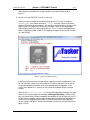
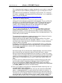
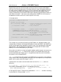
5. So now I can say EXECUTE (use F5 as short cut).
You will see the simulated device working away on your PC screen. If the define
SUPPORT_GLCD hasn’t been removed in config.h there will also be a simulated
graphic LCD displaying some images. This should be removed later for testing on the
target if there is no graphical LCD actually connected. There will also be one port
output toggling away. Let’s take a quick look at it. This is in fact the watchdog routine
which is called every 200ms which is also toggling the output so that we can see that
all is well (PB19]).
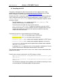
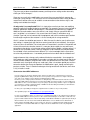
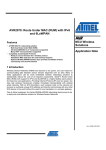
Figure 1. µTasker simulator running
If you hover your mouse over the port which is toggling, or other available ones, you
will see which pin number it has on the device, its name and present use as well as
the possible peripheral functions which it can be programmed to perform. In the
screen shove above this is seen by the line in blue at the bottom of the simulation
window.
Open the file uTasker\Watchdog.c (in the VisualStudio project manager). Put your
cursor on the call to retrigger the watchdog “fnRetriggerWatchdog()” and hit the F9
key (set a break point). Almost immediately the program will halt and you can use F11
to step into the hardware specific routine responsible for triggering the watchdog and
in our case also toggling the port output. The routine writes to the corresponding
device registers and returns. Remove the breakpoint and let the simulated device run
again using F5.
uTaskerV1.4_SAM7X.doc/0.03
6/36
31.07.2009
www.uTasker.com
µTasker – AT91SAM7X Tutorial
V1.4
6. OK. So at least you are convinced that it is really running our project code, but it is
not exactly something to write home about.
Let’s get down to more serious stuff:
There are some menu items in the µTasker environment simulation window. Open
“LAN | Select working NIC” and select the network card you would like the
simulator to use – don’t worry, it will be shared with anything else which is already
using it.
Open a DOS window and do the standard PING test - “ping 192.168.0.3” if you
didn’t need to change anything, or the IP address you defined if you did.
The simulated device should now be responding. That means that your PC has sent
PING test messages to the network and received answers from some network device
(or course our internal simulated device – but no one will know the difference).
You can also try sending the ping test from another PC on the network and it will also
receive an answer.
If you have a network sniffer you can also record the data from the network – don’t
worry if you haven’t used a network sniffer before because we will come back to this
later on and use Wireshark to do the job.
Watch the LAN indicators on the processor’s virtual LAN connector. The left one will
blink green when a frame is received – if it is accepted by the device (matching
address, broadcast or all when in promiscuous mode). The right one will blink red
whenever the simulated device sends a frame to the network.
7. I suggest that you now close the µTasker environment simulation window using the
‘normal’ method File | Exit or by clicking on the close cross in the top right hand
corner.
This standard termination will cause the selected NIC to be saved to a file in the
project simulation directory called NIC.ini and so you will not have to configure it the
next time you start the µTasker environment simulation.
8. Now I’m sure you are not yet satisfied with the progress, so let’s execute the project
again (short cut F5) and this time we will do something a bit more interesting. Start
your web browser (Internet Explorer, Firefox, Chrome, etc.) and establish a
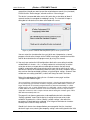
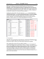
connection with the simulated target: In the URL line type in http://192.168.0.3
(assuming its address has not been changed) and hit the ENTER key. The web
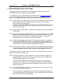
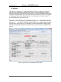
browser will request the start page on the web server, which will return the following
page the first time used:
Figure 2. µTasker web server displaying that it has no web pages loaded
uTaskerV1.4_SAM7X.doc/0.03
7/36
31.07.2009
www.uTasker.com
µTasker – AT91SAM7X Tutorial
V1.4
This is displaying that the page has not been found on the server, which is simply due
to the fact that we haven’t loaded any web pages to it yet, so we will do this as next
step.
Note however that the web browser is displaying the AT91 favicon. This is because
this favicon is embedded in the code and not in the µFileSystem – this is explained in
detail in the user file document
http://www.utasker.com/docs/uTasker/uTaskerUserFiles.PDF
9. Take a look in the project directory
\Applications\uTaskerV1.4\WebPages\WebPagesSAM7X
and you will find the web pages prepared for the demo project. These are HTM, JPG
and GIF files. It is possible to load these pages using FTP clients but these tend to
work quite differently from another and require various setups before they work
smoothly. See the following document for more information on this subject:
http://www.utasker.com/docs/uTasker/uTaskerFTP.PDF
This is the reason that working with simple DOS FTP tends to be the fastest and
simplest method and the bat file Copy_all.bat even does all the work for you.
Check that its content is set to use the correct IP address and then double-click the
bat-file to start the transfer of all of the web pages to the simulated target device. The
transfer takes just a few seconds.
Then go back to the web browser window and make a refresh. Now you will see the
start side and can navigate to a number of other pages.
Before we get into any more details about the web pages and their uses, please
modify and save the Device ID (on the start page – default “uTasker Number 1”) to
any name of your choice and close the µTasker environment simulation window by
using the ‘normal’ exit method.
By doing this, the contents of the device’s simulated FLASH (Flash is used to save
the web pages in the µFileSystem and also any parameters, for example the device
ID which you have modified) are saved to a file in the project simulation directory
called FLASH_SAM7X.ini.
Now execute again (F5) and check that the loaded web pages are all there and that
after a refresh of the start side also the device ID which you chose is correct.
Now you should understand the operation of the simulator; on a normal exit it saves
all present values and settings and on the next start the device has the saved FLASH
contents as at the last program exit. This is exactly how the real device works since,
after a reset, its FLASH contents are as saved – I mean, that is what FLASH is all
about.
If however you have modified FLASH contents and do not want them to be saved,
you can always avoid this by quitting the debugger (short cut SHIFT F5) which
causes the simulator to be stopped without performing the normal save process.
If you wish to start with a fresh device (with blank FLASH contents) then simply delete
the FLASH_SAM7X.ini file from the simulator directory…
10. There is one important setting which we should perform before continuing; that is to
set a MAC address to our new device.
So browse to the “LAN configuration side”, where you will see that the default MAC
address is 00-00-00-00-00-00. This works, but we really should set a new one – as
long as we are not directly connected to the Internet any non-used value can be set.
You make one up. For example set 00-11-22-33-44-55 (watch that the entry format is
correct and always start with 00!) and then click on “modify / validate settings”. The
entry field will be set inactive since it is no longer zero and cannot be changed a
uTaskerV1.4_SAM7X.doc/0.03
8/36
31.07.2009
www.uTasker.com
V1.4
µTasker – AT91SAM7X Tutorial
second time (should your want to reset the value before we commit it to (simulated)
FLASH click on “Reset changes”, otherwise click on “Save changes”.
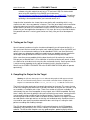
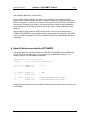
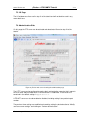
The device is commanded to be reset at this point after a short delay of about 2
seconds to allow it to complete the web page serving. The simulator will open a
dialog box to indicate that it has been terminated with a reset:
Figure 3. µTasker simulator indicating that the processor has just been reset
You can restart the simulator after the reset (which was interpreted as a ‘normal’
program exit and so the changes to the FLASH have also be saved to the hard disk
and will be restored on the next program start) by using F5 as normal.
11. You may have read on the LAN configuration side that the new setting should be
validated within 3 minutes – this is a safety mechanism so that falsely set critical
values do not leave a remote device unreachable and means that we should
establish a connection within three minutes of the new start to verify that all is well,
otherwise the device will automatically delete the newly set values, reload the original
ones and can then be contacted as before, using the original settings. So we will now
validate our new setting (new MAC) so that it will always be used in the future.
Refresh the web pages by clicking first on “Go back to menu page” and then
“Configure LAN Interface” again.
You may well have a shock because it doesn’t respond….but don’t get worried because your
PC may still be trying to reach the IP address using the previous MAC address, which is no
longer valid (hence an incorrectly configured device can become unreachable). In a DOS
windows type in “arp –d” which will delete the PC’s ARP table – which is mapping IP address
to MAC addresses and then it will work on the second attempt. Vista PCs may not always
accept this command so wait a couple of minutes before starting the simulator again, until its
ARP table automatically times out.
The page will not allow any parameters to be modified and also the check box
“Settings validated” shows that the device is waiting for the new values to be
validated. To perform this, click on “Modify / validate settings”, after which the
parameters will be displayed as validated. (Don’t forget to terminate the simulator
normally later so that it is really the case).
Should the 3 minutes have elapsed before you managed all that, the simulated
device will again reset, clearing the temporary settings and reverting back to the initial
uTaskerV1.4_SAM7X.doc/0.03
9/36
31.07.2009
www.uTasker.com
µTasker – AT91SAM7X Tutorial
V1.4
MAC address. Just start the simulator again and repeat this step.
While the project is waiting for the critical network changes to be validated you will
notice that the LCD doesn’t display anything. As soon as the validation sequence has
been completed also the LCD display demonstration will start running as normal.
12. Now you may be thinking that it is all well and good having a web server running on a
device, sitting somewhere on the Internet but you probably want to use the device for
controlling something - in its simplest form by switching something on or off. Using a
relay this could be something quite powerful which can also have really useful
benefits; imagine browsing to your device and commanding it to open the blinds or
turn on the lawn sprinkler…the list of possibilities is almost endless…
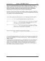
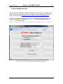
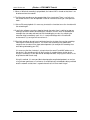
Look at the simulated AT91SAM7X and imagine that you have connected your lawn
sprinkler to the output Port PB22. Presently it is at the state input ‘1’ [signified by ‘^’],
the default state when the software starts since there is a pull-up in the device. Now
click on the link menu page to “Open an I/O window” – it is shown in the following
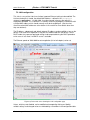
screen shot. Notice that the port PB22 is being displayed as an input and its digital
value as active (‘1’) in its check box.
Figure 4. µTasker web server showing the I/O control page
uTaskerV1.4_SAM7X.doc/0.03
10/36
31.07.2009
www.uTasker.com
V1.4
µTasker – AT91SAM7X Tutorial
Do a quick test: Hover your mouse over the port PB22 in the simulator – it will tell you
which pin it is on your device. Now click – this has toggled the simulated input (each
time you click, it will change state again) – leave it at the low state ‘0’, displayed as ‘v’.
Now refresh the I/O web page by clicking in the Refresh button.
What is the web page now displaying? If it is behaving correctly it will of course be
displaying the new port input state.
Now we can configure it as an output and control its state from the I/O page:
Set PB22 to be an output, rather than an input and click on “Modify configuration”.
Afterwards set the port state to ‘1’ by setting the first port value from the left and click
on “Modify outputs”. Watch the state of Port PB22 on the simulated device – you will
see that the output is now set and now your lawn would get the water it has been
waiting for!
Set the state to ‘0’ and it will be turned off. In this example web page, all of the 4
Ports PB22..PB19 outputs can be controlled individually.
PB19 is used as a RUN LED in the demo project and so is configured as an output by
default, as is PB20.
If you would like a certain setting to be returned after every reset of the device, simply
save the setting by clicking on “Save settings as default configuration” and you will
see that they are indeed set automatically when the device is started the next time.
The demo project includes also 16 user controllable outputs. These are automatically
configured as outputs in the project code and can be seen as outputs with state ‘0’
when looking at the simulator. If you now click on the user defined outputs on the I/O
page you will see that they immediately toggle their port output and the state is either
displayed as a grey button when ‘0’ or as red buttons when ‘1’. Also the present state
of the 16 outputs can be saved as default states when the target starts the next time.
Note that these outputs can be mapped to any port and port bit in the demo project –
it shows a useful example of flexible independent output control.
Note also that the outputs 1, 2, 3 and 10 are used by the LCD interface and so cannot
be modified when the graphical LCD is defined.
13. The last setting which we will change before taking a look at the project on the target
hardware is to activate HTTP user authentication and disable the FTP server so that
no one else without our password has entry to the web server and no sneaky person
can change the web pages which we have just programmed…
Browse to the administration page, deactivate FTP and activate HTTP server
authentication before selecting the action to “Modify and save server settings”. Finally
click on “Perform desired action” and close your web browser..
Open the web browser again and enter the device’s address http://192.168.0.3 (or
your address) and this time you will need to enter the user name “ADMIN” and
password “uTasker” to get in.
Try to do something with the FTP server (like transfer the file with Copy_all.bat or
delete the file system contents with delete_all.bat) and you will find that it simply
won’t work anymore. This is because the FTP server is no longer running in the
simulated device and you can rest assured than no one out there will be able to
change anything which you have loaded.
You probable noticed a button at the bottom of the administration page which allows
a file to be searched for and uploaded to the target as a new software version. This is
an example of using the HTTP POST method to transfer data to the embedded
device. The µTasker project for the SAM7X supports the upload of complete new
uTaskerV1.4_SAM7X.doc/0.03
11/36
31.07.2009
www.uTasker.com
V1.4
µTasker – AT91SAM7X Tutorial
software using this method (as well as by FTP and even USB). For further details
about using this capability on the SAM7X see the document
http://www.utasker.com/docs/uTasker/BM-Booloader_for_SAM7X.PDF :You will see
that you will then be able to develop code for a real target on the internet, including
uploading it from anywhere where you have web access to it!
I hope that the introduction has shown that we are dealing with something which is very
simple to use but is also very powerful in features. There are lots of details which need to be
learned to understand and use everything to its fullest capabilities and it is up to you to
decide whether you want this or would like to simply use the µTasker and its capabilities as a
platform for your own application development. In any case you have just learned the basics
of a powerful tool which is not only great fun but can really save you lots of development
time.
3. Testing on the Target
Up until now we have been using the simulator and hopefully you will agree too that it is a
very useful tool. We have tested some quite useful code designed to run on the SAM7X and
done this in an environment enabling us to do embedded IP stuff in real time. We haven’t
actually done any debugging or added new code but you can probably already imagine the
advantages of being able to write and test it on the PC before moving to the target.
At the same time you are probably thinking about how that will all work on the real device.
Perhaps you are worried that it is all a show after all and the real device will remain as dead
as a door nail or at the best crash every time the user breaths heavily. So let’s prove that this
is not the case by repeating the first part of the tutorial, but this time we will go live…
We will use the ATMEL AT91SAM7X-EK or the OLIMEX SAM7X-EX256 (both will operate
equivalently).
4. Compiling the Project for the Target
Warning: the µTasker demo project V1.4 is delivered with graphical LCD support activated.
This can cause the SW to hang if there is no real LCD connected. Before compiling for the
target it is recommended to disable SUPPORT_GLCD in config.h so that this cannot occur.
The first thing that we need to do is to compile the project for the target. This means that we
will be cross compiling the code which we already have been testing with the simulator, using
an assembler, a C-compiler and a linker. There are a number of such tools available and
unfortunately they are not all compatible in every aspect, even if ANSI compatible. Basically
there is always the chore of getting the thing to reset from the reset vector, meaning that the
start-up code must be available and at the correct location. Then there are specialities
concerning how we force certain code or variables to certain addresses or regions and how
we need to define interrupts routines so that they are handled correctly. Sometimes there is
also need for some special assembler code which does such things as setting the stack
pointer or enabling and disabling interrupts.
The µTasker demo project for the SAM7X is delivered with projects for IAR Embedded
Workbench (IAR4 and IAR5), Keil uVision3, Rowely Crossworks and a standalone GNU
makefile. The IAR and Keil compilers are very good compilers, producing highly efficient
uTaskerV1.4_SAM7X.doc/0.03
12/36
31.07.2009
www.uTasker.com
µTasker – AT91SAM7X Tutorial
V1.4
code so are recommended for professional work as is Rowley Crossworks if the GCC
compiler is preferred. There are evaluation versions available from all suppliers - which are
generally time or code size limited - for anyone wanting to get a feel for the product,
otherwise it should be possible to get the code up and running with any other compiler
without too much hassle, but it will involve setting up an equivalent project.
By the way, if you can’t wait until you have installed the compiler or got your own project up
and running, there are files delivered with the µTasker which were compiled with the IAR and
GCC compilers and can be downloaded already…
You can find the project file and the target file(s) in the sub-directory called IAR_SAM7X:
uTaskerV1.4.eww This is the IAR Embedded Workbench project work space
Applications\uTaskerV1.4\IAR_SAM7X\Release\Exe\uTaskerV1.4_AT91SAM7X
-EK.bin
This is the file which you can download to an ATMEL
AT91SAM7X-EK evaluation board using SAM-BA
Applications\uTaskerV1.4\IAR_SAM7X\Release\Exe\uTaskerV1.4_SAM7XEX256.bin
This is the file which you can download to an OLIMEX
SAM7X-EX256 evaluation board using SAM-BA
When the release target is compiled it normally produces the output
Applications\uTaskerV1.4\IAR_SAM7X\Release\Exe\uTaske
rV1.4.bin
Using the IAR Embedded Workbench you can open the µTasker project and compiler either
for use with the debugger or as a release version (Project | Edit Configurations… debug or release).
The debug project can be downloaded using a JTAG debugger to the internal SRAM of the
SAM7X on the evaluation board (with 64k SRAM available it can run the µTasker demo
project as long as not all options are active). The release project generates code for
operation from internal FLASH and can best be downloaded using the SAM-BA program
from ATMEL, which will be detailed a little later on.
.
uTaskerV1.4_SAM7X.doc/0.03
13/36
31.07.2009
www.uTasker.com
V1.4
µTasker – AT91SAM7X Tutorial
4.1. Compiling with GCC
The project is delivered with a bat file and make file so that the project can be simply
compiled with the GNU compiler. It is recommended to use the Codesourcery g++ build,
which is available as a free Lite edition at http://www.codesourcery.com/
Compiling with GCC is also greatly simplified when working from VisualStudio by adding the
step as a post build step to the normal simulator compile process. When the target Win32
uTasker SAM7X plus GNU build is selected as active configuration the process will be
executed as follows:
-
The GCC directory GNU_SAM7X contains the bat file Build_SAM7X.bat. This
directory will be selected as working directory
-
The bat file will be executed and starts the GCC make file
make_uTaskerV1.4_GNU_SAM7X. The bat file also contains a path to the GCC
binaries on the local PC – if no path variables have been configured when the GCC
compiler was installed this path can be set manually to enable the make utility,
compiler and linker to be found.
The following target files are generated during the GCC build step:
-
uTaskerV1.4.s19: this is a stand-alone target in SREC format
-
uTaskerV1.4.bin: this is a stand-alone target as binary file
-
uTaskerV1.4_BM.s19: this is a boot loader compatible application in SREC format
-
uTaskerV1.4_BM.bin: this is a boot loader compatible application as binary file
-
uTaskerBM.bin: this is a target containing boot loader and boot loader compatible
application in binary format.
-
H_Upload.bin: this is an application which can be uploaded via web browser. See the
µTasker ‘Bare-Minimum’ boot loader documentation for more details.
The stand-alone target can be used for first tests since it doesn’t require a boot loader to be
compiled and installed.
Pre-built release images can be found in the GCC directory as follows:
Applications\uTaskerV1.4\IAR_SAM7X\Release\Exe\uTaskerV1.4_AT91
SAM7X-EK.bin
Applications\uTaskerV1.4\IAR_SAM7X\Release\Exe\uTaskerV1.4_SAM7
X-EX256.bin
The GCC build is displayed in the log windows of VisualStudio and warnings or errors
are counted by the VisualStudio compiler during the process.
uTaskerV1.4_SAM7X.doc/0.03
14/36
31.07.2009
www.uTasker.com
V1.4
µTasker – AT91SAM7X Tutorial
5. Downloading the Code to the Target
The following explains how to download the FLASH based target code to the ATMEL
AT91SAM7X-EK using the SAM-BA utility from ATMEL.
The SAM-BA utility can be downloaded from the ATMEL web site http://www.at91.com/ as
part of the AT91-ISP tool package. Once you have installed the tool package you can start.
Here’s a set by step guide so that it should work with no hassles the first time for you:
Step 1: Connect a cross over cable between the ATMEL AT91SAM7X-EK connector labelled
SERIAL DEBUG PORT and a COM port on your PC. The cross over cable is
delivered with the evaluation board.
Alternatively connect the USB device connector to a free USB socket on the PC – this
will only work when the SAM7X is fully erased; see Step 3 if this is not yet the case
and then return to step 1.
Step 2: Power on the evaluation board – its power LED should light. Power can be supplied
via USB cable.
Step 3. Short circuit the jumper marked ERASE. This will cause the complete internal FLASH
to be erased so that we know that everything is fresh and that all NV bits (non-volatile
flag bits) in the device have been reset. Reposition the jumper as it originally was
(connected to only one of the two pins) and reset the board.
Step 4. Start the SAM-BA program and select the COM port which you have connected and
the target AT91SAM7X256-EK. (If you have connected via USB it will display the
USB interface as alternative, possibly as virtual COM port depending on the operating
system used). Then start the connection by clicking on “Connect”.
Step 5. Assuming the connection is successful you will see a window allowing you to display
the internal memory contents of the device and also load new code to FLASH. Fill out
the file to be loaded in “Send File Name” and then start by clicking on “Send File”.
The loading takes several seconds after which the tool will ask you whether you want to lock
regions in the FLASH. Answer with “NO”.
Step 6. Although the program has been loaded into the internal FLASH of the SAM7X you
would find that it can still not run. The reason is that the device will still boot into its
SAM-BA debug program and not to our code.
To arrange for your board to actually boot from the new code it is necessary to
program a NV bit. To do this, use the “Script” called “Boot from FLASH (GPNVM2)”
and execute it. This will program the corresponding bit to the correct state so that our
code will actually start.
Step 7. Quit the SAM-BA program and reset the evaluation board. You will see that it is now
running the µTasker demo program!!
Since the FLASH was completely deleted, it will start using default parameters and
have no web pages loaded. Therefore you will have to repeat the steps in the tutorial,
after which the web server will be complete.
uTaskerV1.4_SAM7X.doc/0.03
15/36
31.07.2009
www.uTasker.com
V1.4
µTasker – AT91SAM7X Tutorial
You should be done within a few minutes….
Are you surprised that it behaves the same as the simulator? You shouldn’t really be
because that is exactly what the simulator is all about. It allows you to test your real code in
real time and once it is working as you want it to, then you can transfer it to the real target. In
fact you will find that your real target is not really necessary for most of your development
work. Develop on the simulator and ship on the target – that is the way to do things really
efficiently.
Note that the I/O page allows the LEDs and port lines on the I/O port connector on the
ATMEL AT91SAM7X-EK to be controlled and the state of these to be displayed. Two LEDs
are set as outputs be default. If PB19 is reconfigured to be an input the blinking LED will no
longer light.
6. Specific Notes concerning the AT91SAM7X
The demo project is designed to work on the SAM7X512, SAM7X256 and the SAM7X128.
For this reason the memory map is set up to use only the SAM7X128 resources. The
memory map thus has the following construction.
0xffffffff – end of memory space
0xfffa0000 – Start of internal peripherals
0x00207fff – SRAM end
0x00200000 – SRAM start
{ 32k }
0x0011ffff – FLASH end
0x00100000 - FLASH start
{ 128k }
0x0001ffff – FLASH end
0x00000000 - FLASH start
{ FLASH ACCESSIBLE ALSO HERE
{ FLASH ACCESSIBLE ALSO HERE
}
}
If larger chips are used this can be modified to make use of the larger internal resources that
are available.
uTaskerV1.4_SAM7X.doc/0.03
16/36
31.07.2009
www.uTasker.com
µTasker – AT91SAM7X Tutorial
V1.4
7. A Tour through the Demo Web Server
Now that you have the possibility to simulate the demo and also run it on the target hardware
it is time to take a more detailed look at what it does and then how it all works. The demo is
designed to give you a practical platform to use as a basis for your own developments so it
would be good to know how it can be best modified to suite your own needs.
7.1. Menu
Figure 5. µTasker web server showing the menu page
Serial number – this is a decimal representation of the MAC address programmed in the
device. Since the MAC address is normally unique it can serve also as a serial number if
required. Notice that the serial number is displayed in grey and cannot be modified
(disabled).
uTaskerV1.4_SAM7X.doc/0.03
17/36
31.07.2009
www.uTasker.com
µTasker – AT91SAM7X Tutorial
V1.4
Software version – this is a string which is defined in application.h. It is also disabled
so that it cannot be modified via the web side.
Device ID – this is a string defined in the cParameters structure in application.c. The
default value can be set in code and also modified via the web page. When ‘Save new
device ID’ is clicked, the new value is also saved to a parameter block in the internal flash so
that it remains valid after the next reset or power up.
Menu – There are links to several other web pages allowing specific configurations to be
displayed and modified.
Email address – If you have configured the demo project to support SMTP (#define
USE_SMTP in config.h) then it is possible to enter an email address and send a test email
to it. This entry is disabled if the support is not active in the project.
Note that it is necessary to configure some SMTP settings before an email can actually be
sent – the default settings will not work since they are fictive and will not correspond with
your email provider. Full details to the SMTP and its use in the µTasker demo project are
given in the document http://www.utasker.com/docs/uTasker/uTaskerSMTP.PDF
Logo and upload field – The µTasker logo was uploaded to the file system as a GIF file
when the files were loaded. It is possible to change this logo for a different GIF file by
selecting a GIF and pressing the “Upload now” button. The GIF may be up to 6k in size.
uTaskerV1.4_SAM7X.doc/0.03
18/36
31.07.2009
www.uTasker.com
V1.4
µTasker – AT91SAM7X Tutorial
7.2. LAN configuration
This side is a very critical side since it allows important Ethernet settings to be modified. The
first time the device is started, the default MAC address – defined in the cParameters
structure in application.c - is 0-0-0-0-0-0. It can be changed just once, after which it is
displayed as disabled. This is because it is normally necessary to program a new device with
a unique MAC address which should normally never be changed again. (See the short
discussion about MAC addresses at the bottom is this section for some details about how
they are obtained.)
The IP address, subnet mask and default gateway IP address can be modified as long as the
device is not set to DHCP operation. If they are first modified and then the device is set to
DHCP mode, they represent preferred settings to be requested during the DHCP procedure
or for use as a last resort if no DHCP server is available.
The Ethernet speeds of 10M, 100M or auto-negotiation (full or half-duplex) can be set.
Figure 6. µTasker web server showing the LAN configuration page
Values, which are not disabled, can be modified and accepted by clicking on “Modify /
validate settings” and changed values are indicated by a check box in the configuration table.
uTaskerV1.4_SAM7X.doc/0.03
19/36
31.07.2009
www.uTasker.com
µTasker – AT91SAM7X Tutorial
V1.4
They have not yet been committed to memory and the previous setting can be returned by
clicking on “Reset changes”.
Once you are sure that the modifications are correct, they are saved to flash memory by
clicking on “Save changes”. This will cause also a reset of the device after a delay of about 1
second and it will be necessary to establish a new connection to the device using its new
settings and validate the changes.
So why make it so complicated? Well it is simply to be sure that you have not modifying
something which will render the device unreachable. For example, you may have changed its
Ethernet speed from 100M to 10M although it is connected to a hub which only supports
100M and, to make matters worse, the device is not simply sitting on your office desk at
arm’s length but is at a customer’s site several hours drive away. It would be a nasty
situation if you had just lost contact with the equipment and have to somehow get it back on
line although everyone at the customer’s site has already left for a long weekend…
So this is where the validation part comes in. After the reset, the device sees that there are
new settings in memory but also that these are only provisional (not validated) - the original
values are also still available. These new values are nevertheless used for a ‘trial-period’ and
a timer of three minutes duration started. It is now your job to establish a new web server
connection to the device, using the new settings and to click on “Modify / validate settings”. If
you do this the check box names “Settings validated” will be checked, the new parameters
are validated in flash and the old ones deleted. This in the knowledge that the new values
are also really workable ones – how would you otherwise have been able to validate them?
Imagine however that a change really rendered the device unreachable – for example the
LAN speed was really incompatible or you made a mistake with the subnet mask. After three
minutes without validation, the provisional values are deleted from flash and, after a further
automatic reset, the original settings are used again. After a short down period you can then
connect as before the change and perform the modifications again, though correcting the
previous mistake. There is therefore no danger of losing contact with the device, even when
a ‘silly’ mistake is made.
Some notes about MAC addresses
If you are using your own device behind a router and it is not visible to the 'outside world' you can in fact
program any MAC address that you like because it is in a private area. It just has to be unique in this private
area. (This is also valid for a device sitting in a Demiliterized Zone- DMZ)
If however you are selling a product or the device is sitting directly on the Internet then it must have a world
wide unique MAC address which has to be purchased from IEEE. It is purchased either as a block (IAB) of 4k
MAC addresses at a cost of about $500, or if you are going to produce a large number of pieces of equipment
you can purchase a unique company ID (OUI) of 16Million for about $1'600 (plus $2'000 if you don't want the
OUI to be registered on the public listing).
It is then your responsibility to manage the assignment of these addresses in your own products.
The registration page is at: http://standards.ieee.org/regauth/index.html
For any one just wanting to make one or two pieces of equipment for hobby use it is a bit much to pay $500 for
a bunch of MAC addresses and use just one or two of them. Unfortunately it is no allowed to sell the rest on to
people in similar situation because a block must always remain with the individual or organisation purchasing it.
One trick which is often used is to find out what the MAC address is in an old NIC from an old PC which is
being scrapped. This MAC address is then used in your own piece of equipment and the old NIC destroyed.
You can then be sure that the MAC address is unique and can not disturb when used for any imaginable
application.
uTaskerV1.4_SAM7X.doc/0.03
20/36
31.07.2009
www.uTasker.com
V1.4
µTasker – AT91SAM7X Tutorial
7.3. Serial Configuration
This web page allows the debug interface UART in the SAM7X to be set. See the UART
User’s guide for some more details of this interface:
http://www.utasker.com/docs/uTasker/uTaskerUART.PDF
Figure 7. µTasker web server showing the serial interface configuration page
uTaskerV1.4_SAM7X.doc/0.03
21/36
31.07.2009
www.uTasker.com
µTasker – AT91SAM7X Tutorial
V1.4
7.4. Statistics
The statistics window opens in a separate window and displays a table of the number of
Ethernet frames counted by the Ethernet task. These are classified according to whether
they were transmitted, received for the local IP address or received as broadcast frames and
divided into IP protocol types. Since the values can continue to change, the user can update
the window by clicking on the “Refresh” button. It is also possible to reset the counters if
desired by clicking on “Reset frame stats”.
The contents of the ARP cache is also displayed and can be cleared by clicking on “Delete
ARP entries”. These are equivalent to the DOS commands arp –a to display the local ARP
cache and arp –d to delete it. Notice that when the ARP cache is deleted via the web page
there will always remain one entry, this being the PC which commanded the deletion of the
ARP table and updated the table. Due to the network activity it will always immediately be reentered…
Figure 8. µTasker web server showing the statistics page
uTaskerV1.4_SAM7X.doc/0.03
22/36
31.07.2009
www.uTasker.com
V1.4
µTasker – AT91SAM7X Tutorial
7.5. I/O Page
The I/O window was discussed in step 11 of the tutorial and will not be discussed in any
more detail here.
7.6. Administration Side
On this page the FTP server can be activated and deactivated. See also step 12 of the
tutorial.
Figure 9. µTasker web server showing the administration page
The HTTP server can be configured to require basic authentication, meaning that it requests
the user name and password when a new connection is established. These values are
contained in the default settings in application.c.
A TELNET server can also be enabled or disabled, including setting it to a particular port
number.
The previous three settings are modified and saved by setting the desired action to “Modify
and save server settings” and clicking on “Perform desired action”.
uTaskerV1.4_SAM7X.doc/0.03
23/36
31.07.2009
www.uTasker.com
µTasker – AT91SAM7X Tutorial
V1.4
A further action is “Restore factory settings” which returns the default settings as defined in
application.c. This also provokes a reset of the device and if the default settings cause
the network values to be modified it will automatically start a three minute validation period
meaning that it will also be necessary to establish a connection using the ‘factory settings’
and validate them before the original ones will become permanent. This is again to ensure
that there is no danger of losing contact with a remote device. Note that the MAC address is
not reset since the Mac address should always remain unchanged in the device.
The last action is a simple reset of the device.
Memory Utilisation
HEAP – the used heap and the maximum defined heap are displayed. Note here that the
simulator will often display that more heap is used as needed in the real target due to the fact
that some variables will be of different sizes when running on a PC compared to an
embedded target. It allows the real use on the target to be monitored and the user can then
optimise the amount of heap allocated to just support the worst case.
STACK – the amount of stack which has not been used (safety margin) is measured and
displayed. As long as the value remains larger than 0 the system is not experiencing any
memory difficulties. A value of zero indicates a critical situation and must be reviewed. The
simulator however doesn’t perform this stack monitoring and will always display zero; its use
is on the target where resources need to be monitored carefully.
The methods used for the memory monitoring are detailed in the µTasker main
documentation.
Present Time – If the demo project is configured to collect the timer from a time server, this
displays the present time. The time may also be available if the device which the µTasker is
operating on processes a RTC.
Running Time - The time since the device started, or since the last reset, is displayed. This
is useful when monitoring a remote device to ensure that it is indeed operating stably since a
watchdog reset due to a software error would allow the device to remover but possibly not
enable its occurrence to be readily detected.
Upload new software
See the following µTasker documents for further details about using the firmware upload
capabilities of the µTasker project. This uses the HTTP post method to transfer new software
to the target.
•
http://www.utasker.com/docs/uTasker/uTaskerBoot_003.PDF
•
http://www.utasker.com/docs/uTasker/BM-Booloader_for_SAM7X.PDF
uTaskerV1.4_SAM7X.doc/0.03
24/36
31.07.2009
www.uTasker.com
µTasker – AT91SAM7X Tutorial
V1.4
7.7. LCD Side
When the graphical LCD support is enabled (define SUPPORT_GLCD in config.h). The LCD
page will display the present LCD content. It also allows the user to post am image to be
displayed on the graphical LCD.
Figure 10. LCD page showing the present LCD image
For full details about the graphical LCD support in the project please consult the LCD User’s
Guide at http://www.utasker.com/docs/uTasker/uTaskerLCD.PDF
uTaskerV1.4_SAM7X.doc/0.03
25/36
31.07.2009
www.uTasker.com
µTasker – AT91SAM7X Tutorial
V1.4
7.8. Email Configuration Side
The standard set of web pages loaded to the SAM7X does not include a setup page for the
SMTP server but an alternative page can be temporarily loaded to perform this. For more
details see the document http://www.utasker.com/docs/uTasker/uTaskerSMTP.PDF
The SMTP configuration can be performed on this web page corresponding to the email
provider’s requirements. The page KEmailSetup.htm has been loaded in place of
Kadmin.htm (from the directory
\Applications\uTaskerV1.4\WebPages\WebPagesSAM7X\AlternativePages)
Figure 11. µTasker web server showing the Email configuration page
uTaskerV1.4_SAM7X.doc/0.03
26/36
31.07.2009
www.uTasker.com
µTasker – AT91SAM7X Tutorial
V1.4
7.9. Dynamic Content Generation Side
The alternative web page E_multiplication_table.htm (from
\Applications\uTaskerV1.4\WebPages\WebPagesSAM7X\AlternativePages)
replaces the statistics page and demonstrates a multiplication table which is generated on
demand..
For full details of this operation see the document
http://www.utasker.com/docs/uTasker/uTaskerV1.3_Content_Generation.PDF
Figure 12. Dynamically generated multiplication table
uTaskerV1.4_SAM7X.doc/0.03
27/36
31.07.2009
www.uTasker.com
8.
µTasker – AT91SAM7X Tutorial
V1.4
Developing – Testing - Debugging
The demo project is designed to demonstrate a typical use of the operating system and
TCP/IP stack. It is useful in itself as a starting point for many applications and this section
looks at the support for developing, testing and debugging your own applications.
Until now you haven’t actually had to develop anything since the project is delivered fully
functional. To develop your own project it will be necessary to make configuration changes to
suit your own use, to modify existing code and add new code of your own. To learn more
about these aspects it is possible to study the documentation about the µTasker operating
system and protocol stack. A more hands on approach is also possible by letting the demo
project run and walking through the code parts which you are interested in – we did this
briefly at the start of the demo but didn’t linger to discuss any details. Here we will check out
the advantages of the simulator by looking in more depth at a rather more complicated
debugging session.
Debugging is performed for a number of reasons. It is a natural consequence of the test
phase where unexpected program behaviour is experienced and the causes and reasons
need to be understood before correcting the code. It is often also an integral part of the test
phase itself when code reviews are performed, exception handling is to be exercised or
software validation is required. The simulator allows a high degree of tests to be performed in
comfort before going to the target testing phase, where such reviews would be rather more
complicated.
So let’s test something in the demo project. We’ll test the simple PING ECHO utility which we
already used once and we’ll see how we can get to know the software in a very convenient
and efficient manner. We will see how we can manipulate the operation to test and validate
special cases and to make corrections in the code (and verify them too). First we will work
ON LINE with the simulator, meaning that the simulator will be running effectively in real time
and we will capture and analyse events. Afterwards we will see how to do the same OFF
LINE, using a recording of the first case (which could also be a recording made when using a
real target).
Introducing Wireshark
If you are using the µTasker then you will certainly be wanting to make use of its network
capabilities and a tool to monitor network activity is essential. These are often called Network
Sniffers since they can monitor, record and analyse network activity by watching what
happens on the local Ethernet connection. The µTasker was designed with and around
Wireshark (previously called Ethereal), a free and powerful network Sniffer. You can
download this from http://www.wireshark.org/
If you haven’t this program then don’t delay – download it and install it and then we will get
down to some work.
uTaskerV1.4_SAM7X.doc/0.03
28/36
31.07.2009
www.uTasker.com
V1.4
µTasker – AT91SAM7X Tutorial
Now do the following steps:
1. Start the demo project simulation as described in the first tutorial.
2. Open a DOS window and prepare the PING command “ping 192.168.0.3”.
3. Start Wireshark and start monitoring the traffic on your local network (Capture | Start ->
OK).
4. Enter return in the DOS windows so that the PING test is started.
5. Wait until the PING test has completed; there are normally 4 test messages sent.
6. Stop the Wireshark recording and save it to the directory
Applications\uTaskerV1.4\Simulator\Ethereal\ with the name ping.eth
At this stage you can also look at the contents of the Wireshark recording and you will see
something like the following:
No.
1
2
3
4
5
6
7
8
9
10
Time
0.437770
0.439926
0.439933
0.449898
1.441345
1.441650
2.442782
2.442915
3.444225
3.444344
Source
Destination
192.168.0.100
Broadcast
00:11:22_33:44:55 192.168.0.100
192.168.0.100
192.168.0.3
192.168.0.3
192.168.0.100
192.168.0.100
192.168.0.3
192.168.0.3
192.168.0.100
192.168.0.100
192.168.0.3
192.168.0.3
192.168.0.100
192.168.0.100
192.168.0.3
192.168.0.3
192.168.0.100
Prot
ARP
ARP
ICMP
ICMP
ICMP
ICMP
ICMP
ICMP
ICMP
ICMP
Info
Who has 192.168.0.3? Tell192.168.0.100
192.168.0.3 is at 00:11:22:33:44:5
Echo (ping) request
Echo (ping) reply
Echo (ping) request
Echo (ping) reply
Echo (ping) request
Echo (ping) reply
Echo (ping) request
Echo (ping) reply
It is also very possible that there are other frames on the network from other computers or
your own computer talking with others, and it is possible to perform many filtering functions to
remove these either from the visible display or from the recoding file – just look in the
Wireshark Help.
Here my PC has the local address 192.168.0.102 and initially doesn’t know how to find the
destination 192.168.03. An ARP resolve is sent and the simulator responds to it, informing at
which MAC address its IP can be found at.
The ping test is repeated four times, each time receiving a reply from the simulator.
So let’s see in some more detail how we can check the operation of this procedure and we
will begin at the deepest point in the code, the receiving interrupt routine in the Ethernet
driver, which is called when a complete Ethernet frame has been received.
In the VisualStudio project, locate the file SAM7X.c (in hardware\SAM7X\) and search for
the Ethernet reception interrupt routine called EMAC_Interrupt().In fact this interrupt
routine is common to all Ethernet interrupts so put a break point in the part which detects that
the RCOMP flag has been set by positioning the cursor over the appropriate line of the routine
and pressing F9.
It may be that you will find the code stopping at this break point before starting the ping test,
which is probably because the code is receiving broadcast frames from your network. If this
happens before you start the ping test just press F5 to let it run again (which you may have
to repeat if there is a lot of activity…).
uTaskerV1.4_SAM7X.doc/0.03
29/36
31.07.2009
www.uTasker.com
V1.4
µTasker – AT91SAM7X Tutorial
Repeat the ping test from the DOS window and the execution will stop at the breakpoint
which you set in the interrupt routine. Since there will be no answer to the ping test because
our code has been stopped, the ping test(s) will fail, but we don’t worry about that since we
have caught the event which we are going to use to analyse the flow through the driver,
memory, the operating system and the ICMP routine. Now we can get to know the code in as
much detail as we want…..and since we are working with the SAM7X, this will also give us
the opportunity to look at some of its internal registers on the way.
A. Interrupt routine
__interrupt void EMAC_Interrupt(void)
{
unsigned long ulInterrupts;
while (ulInterrupts = EMAC_ISR) { // read the interrupt status register, which
clears all interrupts
if (ulInterrupts & TCOMP) {
// frame tramsmitted
…
}
if (ulInterrupts & RCOMP) {
// complete reception frame available
((ETHERNETQue*)(eth_rx_control))->ETH_queue.chars =
(QUEUE_TRANSFER)(ptrRxBd->bd_details & BD_INFO_LENGTH_OF_FRAME_MASK);
// put the length of the received frame
in the buffer
fnWrite(INTERNAL_ROUTE, (unsigned char*)EMAC_RX_int_message, HEADER_LENGTH);
// Inform the Ethernet task
}
ulInterrupts &= ~(TCOMP | RCOMP);
}
}
The simulator has just received a frame for our MAC address or a broadcast address (the
simulator doesn’t disturb us with foreign MAC addresses when the EMAC in the SAM7X has
not be set up for promiscuous operation) and here we are in the interrupt routine. Now don’t
forget that this is the real code which will operate on your target and if this doesn’t work
properly it will also not work properly on your target.
We see that such routines are necessarily quite hardware specific. Here we see accesses to
the internal register, EMAC_ISR. Search for this registers in the SAM7X data sheet if you
want to read exactly how it works; here is a very quick overview where we will also look at
the registers in the simulated SAM7X.
EMAC_ISR is the interrupt status register in the EMAC. We can search for it in our project by
using “search in files”, ensuring that the search path starts at the highest level in the µTasker
project, and using the search files of type *.c and *.h.
It will be found in the code at several locations but also in the file sam7x.h, where it is
defined as:
#define EMAC_ISR
*(volatile unsigned long*)(EMAC_PERIPHERAL_BLOCK + 0x24)
where EMAC_PERIPHERAL_BLOCK is also defined locally twice:
#define EMAC_PERIPHERAL_BLOCK
#define EMAC_PERIPHERAL_BLOCK
((unsigned char *)(&ucSAM7x.ucSimMAC))
0xFFFDC000
and
On the target the register is located at long word address 0xFFFDC000 and when simulating
it can be found in a structure called ucSAM7X.
uTaskerV1.4_SAM7X.doc/0.03
30/36
31.07.2009
www.uTasker.com
V1.4
µTasker – AT91SAM7X Tutorial
Double click on the word ucSAM7X so that it becomes highlighted and then drag it into the
watch window (Shift F9 opens a quick watch window). Expand the structure by clicking on
the cross to the left of the name and you will see the various internal peripheral divided into
sub-blocks. EMAC_ISR is in the sub-block usSimMAC so we also expand this sub-structure
by clicking on the cross left of its name.
In the sub-block you will see all of the EMAC registers listed in the order in which they occur
in memory as well as showing their present values. Step the code (F10) and you will see that
the length of the received frame is read from a location from memory pointed to by the
present EMAC buffer description and saved before sending an internal message defined by
static const unsigned char EMAC_RXA_int_message[ HEADER_LENGTH ] = { 0, 0 ,
TASK_ETHERNET, INTERRUPT_EVENT, EMAC_RXA_INTERRUPT };
// define fixed interrupt event
This internal message is sent to TASK_ETHERNET to inform that a frame has been received
and is as such a method used by the operating system to wake up this Ethernet task. If you
want to, you can also step into the write function to see the internal workings of how it wakes
up the receiver task but I will assume here that all is working well and will just move to
TASK_ETHERNET to see it actually receiving this interrupt message.
Before doing the next step, remove the break point in the interrupt routine by setting the
cursor to its line and hitting F9.
B. Receive Task
Now open the file ethernet.c in the project directory TCP/IP and set the cursor to the
bracket after the tasks routine void fnTaskEthernet(TTASKTABLE *ptrTaskTable)
With a right click, the menu item “Run to cursor” can be executed and you will see that this
task is indeed started immediately since the program execution stops at this line.
Step slowly through the code using F10 and observe that the task reads the contents and
interprets it as an INTERRUPT_EVENT. It calls fnEthernetEvent() to learn about the
length of the received frame and to get a pointer to it – use F11 to step into this routine if you
would like to see its internal workings, which I will not discuss here.
You will see that the pointer to the frame is called rx_frame and it is defined as a pointer to
an ETHERNET_FRAME. Now, as we all know, a pointer is just a pointer – but the fact that it is
defined as a pointer to a certain structure will help us greatly to interpret the contents of the
received frame. We will first look at the frame as it is in memory and then how it looks in the
debugger as a structure.
C. Receive Frame
Let’s start with simply looking at the raw data which we have just received from the Ethernet.
Do this by placing rx_frame in a watch windows and expanding it so that the length of the
frame (frame_size) and the pointer to the data (ptEth) are visible [do you recognise the
length from earlier?]. ptEth has a value which you can double click on and insert to the clip
board before pasting it into the address field of a memory display window (if this window is
not yet visible, activate it in the debug menu). Now you will see the raw Ethernet frame in
memory – note that this is in the local computer’s memory and the address of its location has
nothing to do with the storage place on the real target.
uTaskerV1.4_SAM7X.doc/0.03
31/36
31.07.2009
www.uTasker.com
µTasker – AT91SAM7X Tutorial
V1.4
Now it is not exactly easy to understand the data but you should just be able to make out the
MAC address at the beginning and the content of the ping test usually consists of
abcdefghijk… which is easily recognised. (Warning: it is possible that the frame which you
actually captured is not the ping test but some other network activity, or even an ARP frame
if the PC sending the ping had to re-resolve its MAC address. If this happens to be the case,
set a break point at the location which the program is at and let it run again and hopefully it
will come to this location the next time with the correct contents…).
Go back to the watch windows where the structure of rx_frame is being displayed and
expand the sub-structure ptEth. This will start making life rather easier since it is showing
us that the Ethernet frame is made up of a destination MAC address, a source MAC address,
an Ethernet frame type and some data. Expand each sub-structure to see their exact
contents, although it is not yet worth expanding the data field since we don’t know what
protocol its contents represent so it will not be displayed better at the moment.
D. Frame protocol
Step slowly using F10 and you will see that the frame is check for the ARP protocol, which it
won’t be if it is the ping request which we are analysing. It then calls fnHandleIP(), which
we will enter using F11 since all such TCP/IP frames are built on the IP protocol.
After a couple of basic checks of IP frame validity, the pointer received_ip_packet is
assigned to the data part of the received frame. Again this structure is very valuable to us
since it can be dragged into the watch windows and now we suddenly understand how the IP
fields are constructed. We can expand any field we want to see, such as the IP address of
the source sending the IP frame. Note that when looking at IP frames is may be worth
requesting the debugger to display the contents in decimal rather than in hexadecimal by
using right click and then selecting the display mode. The IP addresses are then better
understandably and afterwards you can set the mode back to hexadecimal display since it is
better for most other data fields.
uTaskerV1.4_SAM7X.doc/0.03
32/36
31.07.2009
www.uTasker.com
µTasker – AT91SAM7X Tutorial
V1.4
If you continue to step through the routine you will see that the IP frame is interpreted to see
whether we are being addressed, it may cause our ARP cache to be updated and the check
sum of the IP frame will also be verified. To return without stepping all the way you can use
SHIFT F11 to return to the ETHERNET task code, where the protocol type is checked.
E. ICMP Handling
Note that each protocol type can be individually activated or deactivated in config.h. ICMP
frames are only handled when the define USE_ICMP is set. If your project doesn’t want to
support ICMP then it can be simply removed…
Step into the ICMP routine (fnHandleICP()) by using F11. You will see that there is also a
checksum in the ICMP field which is verified and the structure ptrICP_frame allows the
ICMP fields to be comfortable viewed in the watch window.
Our frame should be of type ECHO_PING, which can also be individually deactivated in your
project if you want to support ICMP but do not want the ping test to be replied to.
The received frame is sent back, after modifying a few fields, using the call fnSendIP(). I
don’t want to go into details about how the IP frame is constructed – you can see this in
detail by stepping into the routine and observing what happens – but I should mention how
the frame is sent out over the Ethernet since this is again a low level part which uses the
SAM7X registers again. Very briefly you should understand that the SAM7X has been set up
with one transmission buffer into which the data is copied. The data is set up to respect the
ICMP, IP and Ethernet layers as we observed in the received message and, once completely
ready, the transmission is activated.
uTaskerV1.4_SAM7X.doc/0.03
33/36
31.07.2009
www.uTasker.com
µTasker – AT91SAM7X Tutorial
V1.4
This transmission activation takes place in the file sam7x.c in the function fnStartEthTx()
so search for it and set a break point there. Once the program reaches this point it will stop
and you can see which registers are set up and verify that all is correct.
Here you will also see that the simulator comes into play once the data is ready and the
registers have been set up correctly. This code, which will not be discussed here, basically
tries to behave as the EMAC transmitter does by interpreting the register set up and
transmitting the data buffer contents to your local network.
9.
Off-Line Simulation
Normally the simulator, or the target, will have responded to the ping request very quickly
and the ping test would have been successful. We, being human beings, are rather slow and
we probably took several minutes to work our way through the code before your ping reply
was finally sent back. This was of course much too late as the ping test has already
terminated, informing that the test failed.
This is not only a problem with the ping test but with many protocols since they use timers
and expect replies within quite a short time, otherwise an error is assumed and links break
down. Debugging of such protocols can become quite hard work due to this fact.
This is where the µTasker can save the day again since it supports operation in OFF-LINE
mode. This means simply that it can interpret Wireshark recordings as if they were real data
from the network. Since we previously made a recording we can try this out right now!
A. Prepare a break point
I suggest that you set a break point in the ICMP routine itself since we have already seen
how the message arrives there ad this will avoid false triggers due to broadcast frames in
the mean time. Let the project run again by hitting F5.
B. Open the Wireshark recording
In the menu Wireshark select Load Wireshark/Ethereal file to play back.
Then select the ping.eth file which was previously recorded. If the simulation is
repeated, the command Replay last File can be used instead – this is only valid
after the simulator is terminated normally.
Perform this action and the Wireshark file will be interpreted. The times that frames arrived
will be respected – if there is a gap or 1s between two frames then these two frames will also
arrive with a 1s gap. You will see that the recorded ping will be received via the receive
Ethernet interrupt routine and be passed up through the software until the breakpoint in the
ICMP routine is encountered. The difference is that the break point and stepping in code can
not disturb the protocol since also the recording is stopped.
This can be a great advantage when debugging protocols!
Before terminating this discussion there are a few points which should be noted, so here is a
list of all relevant details which could be of use or interest.
uTaskerV1.4_SAM7X.doc/0.03
34/36
31.07.2009
www.uTasker.com
µTasker – AT91SAM7X Tutorial
V1.4
1. When an Wireshark recording is played back, the internal NIC is closed so that there is no
disturbance from the network.
2. The Wireshark recording can be repeated after it has terminated. There is no limit as to
the number of times it can be repeated. Useful for incremental testing of a new piece of
code…
3. After an Ethernet playback it is necessary to restart the simulator to use the simulator with
the network again.
4. If you find a software error when stepping through the code, there is nothing to stop you
making a correction without terminating the simulation session. Often VisualStudio can
recompile the new code and continue with the debugging session, thus allowing the
correction to be immediately used – this is a major advantage of the VisualStudio
environment! Try it and you will learn to love it…
5. Wireshark recordings do not have to originate from the simulator, they can be recordings
from targets or from foreign devices. This means that recordings of a good known
sequence can also be used as input to developments (for example the recording of an
email being collected by your PC).
It is necessary that the simulator is set up to have the same IP and MAC addresses as
the device in the recording and it will then receive all recorded frames to that device.
Using this recording it is then possible to develop new code, verifying that it reacts as the
original device did at each step.
Using this method, it is even possible to develop quite complicated protocols or services
using a known good case as a reference. It can be basically tested before being switched
onto the network so that there is a good chance that it will even work first go!
uTaskerV1.4_SAM7X.doc/0.03
35/36
31.07.2009
www.uTasker.com
V1.4
µTasker – AT91SAM7X Tutorial
10. Conclusion
This tutorial first introduced the µTasker simulator’s capabilities to execute the demo project
software on a simulated SAM7X. It showed the basics of working with the simulator and its
Ethernet capabilities before turning attention to running the same project on a target board.
By working with Wireshark and the µTasker simulator’s ability to play back Wireshark
recordings through its complete software code, interesting methods for increasing
development, debugging and test efficiency have been demonstrated.
The SAM7X project supports various other features including USB. All features can be
simulated using similar built-in techniques, thus enabling all aspects of real-world embedded
projects to be performed with increased efficiency in comparison with convention
development and debug techniques. Combining the µTasker simulator with the features of
the µTasker demo project represents the fastest method of starting and completing
embedded projects with the supported devices.
Change history:
0.01/4.2.2007: Provisional first draft - .Updated for the V1.3 demo up to side 20.
0.02/30.05.2009: Rework with title page and review for service pack 4.
0.03/31.07.2009: Adapted for µTasker V1.4 with graphical LCD demonstration.
uTaskerV1.4_SAM7X.doc/0.03
36/36
31.07.2009