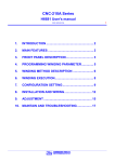
1
CNC-210A Series Technical Manual DOC NO:040610 1. INTRODUCTION .................................................... 2 2. MAIN FEATURES .................................................. 2 3. CONSTRUCTION OF CONTROLLER................... 3 4. INSTALLATION AND WIRING............................... 5 5. ADJUSTMENT ..................................................... 10 6. PROGRAM UPDATE ........................................... 12 7. DATA TRANSMIT................................................. 13 8. MAINTAIN AND TROUBLESHOOTING .............. 14 9. SPECIFICATIONS................................................ 16 έᚊཝҋજ̼ѣࢨ̳Φ TAILY AUTOMATION CO.,LTD. 1 2 CNC-210A Series Technical Manual 1. INTRODUCTION CNC-210A is a series of COIL WINDING MACHINE CONTROLLER developed by TAILY AUTOMATION. It not only retains all the features of previous designs, it also has a low noise level and is less sensitive to external power fluctuation. Furthermore, it also includes a RS-485 network interface, making coil-winding operation easier to manage. CNC-210A also features an integrated design: putting stepper motor driver, DC motor speed controller, brake and power supplier control circuits into one control box, simultaneously achieving size reduction, high performance and low cost. CNC-210A Series offers CNC-210AS “Standard Model” and CNC-210AE "External Connection Model”, depending on whether a close-loop driver is provided for various applications. MODEL Winding Spindle Guiding Traverse CNC-210AS Drive 0.5hp DC motor in directly. Drive two phases 2A STEP motor in directly. CNC-210AE External connect winding spindles motor driver. Drive two phases 2A stepper motor in directly, Or external connect guiding traverse STEP motor driver. 2. MAIN FEATURES Single chip Microprocessor design, has further higher performance and higher functions; it also has less sensitive to external power fluctuation or to external electromagnetic interference. Memory use FLASH ROM, capacity capable storing up to 1000 steps winding data, 9 winding parameters, and 5 options can be independently assigned for each step. Off-power memory retention without battery. Winding speed can be specified using the front panel keypad, resulting in easy programming of multi-step, multi-speed settings. Guiding traverse shaft stepper motor with a constant-current driver offering fast wire guiding speeds. Guiding traverse shaft offering 10 steps moving speed selection. Offering RS-485 interface for PC linking and data transfer. Software can be update through the personal computer. Power input AC100V~120V、220V~240V 600VA(max). έᚊཝҋજ̼ѣࢨ̳Φ TAILY AUTOMATION CO.,LTD. 3 CNC-210A Series Technical Manual 3. CONSTRUCTION OF CONTROLLER 3.1. Internal parts list NAME CNC-210AS CNC-210AE 210-KBD Key pad and display board ○ ○ 210A-CPU Master control board ○ ○ 210A-DVR Motor control board ○ X 210A-EXD Motor control board X ○ 210A-CNB Wire connection board ○ ○ TLP-503D Power supply board ○ ○ 201A-ECB Wire connection board X ○ 210A-CPU-CN1 Flat cable ○ ○ 210A-CPU-CN2 Flat cable ○ ○ 210A-CPU-CN3 Flat cable ○ ○ 210A-DVR-CN1 Cable ○ ○ 210A-DVR-CN2 Cable ○ ○ 210A-DVR-CN4 Cable ○ ○ 210A-DVR-CN5 Cable ○ ○ 210A-ECB-CN1 Cable X ○ 210A-ECB-CN2 Cable X ○ DC12V FAN ○ ○ NOTE “X “ = not used in this model 3.2. Assembly diagram 210-CNB 210-ECB TLP-503D ID:011017 DC12V FAN 210A-DVR or 210A-EXD TLP-503D 2 TLP-503D ID:011017 210-KBD 210A-CPU έᚊཝҋજ̼ѣࢨ̳Φ TAILY AUTOMATION CO.,LTD. CPPU! QPXFS!TX 4 CNC-210A Series Technical Manual 3.3. Internal connectors and cables specification 210A-DVR-CN1 210A-CPU-CN1 360mm 205mm 18AWG 2 MHB-3P 3 1 FC-10Px2 CLIP-10Px2 210A-DVR-CN2 320mm 210A-CPU-CN2 20AWG 205mm MHB-2P MHB-3P 110mm 20AWG 210A-DVR-CN4 125mm 20AWG MHB-3P FC-20Px2 MHB-7P CLIP-20Px2 210A-CPU-CN3 MHB-4P 105mm 200mm 90mm 210A-DVR-CN5 FC-10Px2 210A-ECB-CN2 20AWG CLIP-10Px2 MHB-2P MHB-2P 210A-ECB-CN1 150mm 26AWG MHS-4P MHS-4P 3.4. Internal wiring diagram CN6 210A-CNB CN8 210A-CPU-CN4 CN5 CN4 CN9 210A-CPU-CN2 CN7 2 1 210A-DVR-CN5 CN3 CN2 2 1 MHB-2S CN5 MHB-2S CN1 CN2 CN3 CN3 210A-CPU-CN3 TB1 CN4 210A-DVR/210A-EXD 4 3 2 1 210A-CPU 210-KBD CN6 CN2 CN1 MHS-4S MHB-2S MHB-3S 1 2 3 CN5 1 2 CN1 1 2 3 4 MHB-4S 210A-DVR-CN2 210A-DVR-CN1 CN6 MHB-3S CN2 1 2 3 CN4 3 2 1 BOOT MHB-3S CN3 4 3 2 1 CN1 2 1 CN2 1 2 2 1 XH250-2S POWER SW 1 2 210A-DVR-CN4 7 6 5 4 3 2 1 CN1 3 DC 12V FAN έᚊཝҋજ̼ѣࢨ̳Φ CN7 MHB-2S CN3 CN8 MHB-2S 210A-ECB TLP-503D MHB-7S TAILY AUTOMATION CO.,LTD. MHS-4S 5 CNC-210A Series Technical Manual 4. INSTALLATION AND WIRING The controllers should be operated in an environment that is protected from moisture, corrosive gases, oil mist, and free from airborne dust, metallic particles, and magnetic noise. Normally operate under 10℃~40℃environment. Do not block the intake/exhaust ports of the controller. Otherwise, a fault may occur. Make sure that the power source supplies the correct voltage and is capable of supplying the required current to the controllers. Do not connect or disconnect wires and connectors while power is applied to the controller. Make sure that the machine and controllers are properly grounded. Make sure that the leads and connectors are connected correctly. 4.1. I/O signal Interfaces description Digit input interfaces: Give a signal with a relay, switch or open collector transistor. IP1~IP6,PHA,PHB,PHC,HOME START,STOP,RESET CNC-210AS/AE +24V CNC-210AS/AE +24V +24V +24V +24V SENSOR 2.2K + 4.7K IN PUT SWITCH 4.7K SWITCH IN PUT OUT 2.2K COM COM Digit output interfaces: A lamp, relay or photo coupler can be driven. LAMP1,LAMP2,LAMP3 OP1~OP4 CNC-210AS/AE CNC-210AS/AE LOAD +24V +24V LAMP +24V +24V 2.2K 2.2K 22R OUT PUT OUT PUT MAX: 24V 0.1A MAX: 24V 0.1A Motor control signal interfaces:(for CNC-210AE only) PUS,DIR V_OUT,CW,CCW,H/L MOTOR DRIVER CNC-210AE only MOTOR DRIVER CNC-210AE only +5V V-OUT (DC 0~10V) VIN +5V V+ PUS PUS DIR DIR COM +24V 330R 2.2K H/L HI/LOW CW/RUN CW/RUN CCW/DIR CCW/DIR COM 330R COM έᚊཝҋજ̼ѣࢨ̳Φ TAILY AUTOMATION CO.,LTD. 6 CNC-210A Series Technical Manual 4.2. Accessories List NAME 210A-CN2 210A-CN3 210A-CN4 210A-CN5 210A-CN6 210A-CN7 210A-CN8 HOME-SR CNTB-03B/C DISC START STOP RESET RS-485 Connection box Operate switches connection cable Home sensor connection cable Counting sensor connection cable Aux I/O signal connection cable Pulse output connection cable AC output connection cable Home sensor Counting sensor Counting disc Push button switch Push button switch Push button switch Foot switch RUN/STOP Foot switch Power cord AC Power cord All accessories are optional to purchase. CNC-210AS CNC-210AE ○ ○ ○ ○ ○ ○ ○ ○ ○ ○ X ○ X ○ ○ ○ ○ ○ ○ ○ ○ ○ ○ ○ ○ ○ ○ ○ ○ ○ “X “ = not used in this model 25.0 225.0 10.0 112.0 4.3. Dimensions (unit=mm) 25.0 43.0 163.0 42.0 CNC-210AS/AE 4.0 3.2 x 2 3.2 x 2 3.2 x 2 22.0 51.0 22.0 55.0 23.5 10.0 3.5 7.0 7.0 4.0 23.5 3.5 15.0 14.5 51.0 14.5 7.0 6.0 10.0 10.0 6.0 6.0 10.5 12.0 9.0 13.0 CNTB-03B 1.5 7.0 15.0 7.0 10.5 1.5 1.5 CNTB-03C έᚊཝҋજ̼ѣࢨ̳Φ TAILY AUTOMATION CO.,LTD. HOME-SENSOR 7 CNC-210A Series Technical Manual R2 8 2.0 1.0 8.0 .0 3.0 R1 .0 3 .0 R1 R28 1.0 R10.0 R10.0 3.1 x 4 3.1 x 4 71ƶ 71ƶ ƶ 71 71ƶ ZEROING DISC COUNTING DISC 4.4. Counting system assembly (unit=mm) The counting disc and the turn counter must assembly as below, otherwise it will count improperly. The zeroing disc is not served with the controller. If zero position is necessary for the winding spindle, make a zeroing disc as above and coupling it with counting disc as below. COUNTING DISC ZEROING DISC (OPTION) WINDING SPINDLE ZEROING SENSOR COUNTING SENSORS (MIN) 6.0 (MAX) 1.0 CNTB-03B/03C 4.5. Home sensor assembly (unit=mm) HOME SENSOR must be assembly as below, otherwise a fault may occur. screw guiding traverse shaft 10.0 max. min. min. max. έᚊཝҋજ̼ѣࢨ̳Φ TAILY AUTOMATION CO.,LTD. 6.0 1.0 1.0 home sensor 8 CNC-210A Series Technical Manual 4.6. CN2~CN6 Wiring diagram for CNC-210AS/AE Home Sensor Turn Counter AUX I/O CN3 CN4 CN5 CN6 CN3 CN4 CN5 CN6 +24V Operate Switches CN2 OP1 RS-485 CN7 OP2 OP3 OP4 IP1 IP2 IP3 IP4 COM C0M PHC PHB PHA +24V C0M IP6 HOME IP5 +24V +24V RESET START STOP LAMP3 LAMP2 LAMP1 TR- TR+ 0V DIR PUS +5V Pulse Output COM IP4 IP3 +24V IP2 OP1 IP1 OP2 IP5 OP3 IP6 OP4 AUX I/O 1 2 a 3 b 4 2 1 FOOT SW a 3 1 STOP RS-485 Connection Box b 4 2 a 3 1 START b 4 2 1 RESET 1 HOME-SR Operate Switches CNTB-03B Home Sensor Turn Counter 4.7. Wiring diagram for CNC-210AS Home Sensor Turn Counter AUX I/O CN3 CN4 CN5 CN6 CN8 AC Input AC GND AC AC Output AC AC 1 2 Winding Driver COM CW A H 3 4 Brake CCW Vout F+ F- 5 6 STEP Motor BK+ BK- A A B B 7 8 9 10 11 12 GND M A A B B EARTH AC Input Winding Spindle Motor έᚊཝҋજ̼ѣࢨ̳Φ TAILY AUTOMATION CO.,LTD. +24V Operate Switches CN2 OP1 RS-485 CN7 OP2 OP3 OP4 IP1 IP2 IP3 IP4 COM C0M PHC PHB PHA +24V C0M IP6 HOME IP5 +24V +24V RESET START STOP LAMP3 LAMP2 LAMP1 TR- TR+ 0V DIR PUS +5V Pulse Output DC24V 12W Brake 2Phase 6V 2A Guiding Traverse STEP Motor + + + + 9 CNC-210A Series Technical Manual 4.8. Wiring diagram for CNC-210AE Drive STEP Motor in directly Home Sensor Turn Counter AUX I/O CN3 CN4 CN5 CN6 AC Input Winding Driver AC GND AC COM CW A H 2 3 4 5 6 H/L Vin AC 1 CCW AC CW AC Output Brake CCW Vout F+ F- +24V Operate Switches CN2 OP1 RS-485 CN7 OP2 OP3 OP4 IP1 IP2 IP3 IP4 COM C0M PHC PHB PHA +24V C0M IP6 HOME IP5 +24V +24V RESET START STOP LAMP3 LAMP2 LAMP1 TR- Pulse Output CN8 CN8 TR+ 0V DIR PUS +5V CN7 STEP Motor BK+ BK- A A B B 7 8 9 10 11 12 GND CN8 COM AC GND AC Motor Driver AC AC A A B M AC Output EARTH AC Input (MAX 400W) B Winding Spindle DC24V 12W 2Phase 6V 2A Brake Guiding Traverse Motor STEP Motor External connect STEP Motor driver AC Input AC GND AC 2 3 4 5 6 H/L Vin AC 1 Brake CCW Vout FF+ CCW AC Winding Driver COM CW A H BK- A A B B 7 8 9 10 11 12 CW COM AC GND AC DIR PUS V+ Motor Driver AC AC AC AC M B AC Output EARTH AC Input (MAX 400W) Winding Spindle DC24V 12W Brake Motor έᚊཝҋજ̼ѣࢨ̳Φ TAILY AUTOMATION CO.,LTD. STEP Motor BK+ CN8 B +24V CN6 OP1 AUX I/O CN5 OP2 OP3 OP4 IP1 Turn Counter CN4 A Guiding Traverse IP2 Home Sensor CN3 Step Motor Driver 2PhaseSTEP Motor IP3 Operate Switches CN2 GND A IP4 RS-485 CN7 AC Output CN7 COM C0M PHC PHB PHA +24V C0M IP6 HOME IP5 +24V +24V RESET START STOP LAMP3 LAMP2 LAMP1 TR- Pulse Output CN8 CN8 TR+ 0V DIR PUS +5V CN7 10 CNC-210A Series Technical Manual 5. ADJUSTMENT 5.1. Adjustments for CNC-210AS CL:Maximum Output current limit. 1. Connect a DC Amperes meter between terminal and DC motor as below. 2. In ready mode press to make the DC motor starting rotate and then press holding the winding spindle. 3. Rotate CL to set limited current, show on Amperes meter. ( 2A for 180v DC motor、4A for 90v DC motor). to (The CL have been set by factory before delivery. Only adjust it when change DC motor and replace 210A-DVR driver board.) IR:Torque compensation. 4. Set the winding parameter H.S.、 L.S. in 20, then press to change the DISPLAY shows RPM. Then press key to start winding. 5. Rotate IR potentiometer to make it in same speed during the winding spindle shaft in full-load and unload. Then press key to stop winding. MAX:Maximum winding speed. 1. Set the winding parameter H.S., L.S. in 99, and press key to change the DISPLAY shows RPM. Then press key to start winding. 2. Rotate MAX potentiometer to make the winding speed (RPM) as you want. Then press key to stop winding. DC MOTOR 10A AMPERE METER 0 M 10 10 FUSE2 FUSE1 CN2 RY1 CN1 COIL-24V-DC SCL-DPDT A CN5 L R32 T1 T1 POWER T1 CL AC 100~120V TF808C1 AC 220~240V TF808C2 H R38 C33 R33 CL L H I R MAX IR R33 POWER L MAX CN4 CN3 H TAILY AUTO 210A-DVRID:XXXXXX έᚊཝҋજ̼ѣࢨ̳Φ TAILY AUTOMATION CO.,LTD. R33 AC 100~120V 82K AC 220~240V 47K 11 CNC-210A Series Technical Manual 5.2. Adjustments for CNC-210AE Speed Mode selection To select the speed signal output mode for winding driver. Selected by JP1. 1. V-out mode:Represents the speed signal with DC 0~10v output. 2. H/L mode:Represents the speed signal with HI/LOW lever output. Hi speed with HI lever, low speed with LOW lever. V-out adjust 1. Set the winding parameter H.S., L.S. in 99, and press key to change the DISPLAY shows RPM. Then press key to start winding. 2. Rotate V-out potentiometer to make the winding speed (RPM) as you want. Then press key to stop winding. 3. This function only worked in V-out mode. COM CW RUN CCW F/R Vout H/L TB1 8 7 6 5 4 3 2 1 CN1 12 11 10 9 CN2 FUSE2 FUSE1 CN5 T1 AC 100~120V TF808C1 H/L Vout AC 220~240V TF808C2 JP1 L VR1 H JP2 JP3 CW_CCW CCW Control Mode F/R RUN_F/R CW JP2 JP3 RUN CN6 JP1 Speed Mode Vout ADJ. H/L Vout 1 2 3 T1 AC POWER R32 T1 CN4 CN3 TAILY AUTO 210A-EXD ID:XXXXXX έᚊཝҋજ̼ѣࢨ̳Φ TAILY AUTOMATION CO.,LTD. 12 CNC-210A Series Technical Manual 6. PROGRAM UPDATE The program version of CNC-210A can update through the PC 1. Connect the FLASH-A and RS-232 cable between PC and CNC-210A as below. 2. Put FLASH_A disk into the disk driver (You can also download from www.taily.com.tw), TLP-503D ID:011017 click SETUP.EXE to install software, and then copy the XXXXX.TBN files to the hard disk from TBN_FILE folder. (You can also download from www.taily.com.tw), 3. Click FLASH_A.EXE and follow the procedures below to update program version. T L P -50 3 D ID :0 1 10 1 7 FAX:886-2-29103525 TEL:886-2-29160387 TAILY AUTOMATION CO.,LTD. έᚊཝҋજ̼ѣࢨ̳Φ MADE IN TAIWAN R.O.C. SOURCE PC COM-PORT TAILY AUTO mail:[email protected] VPP http//www.taily.com.tw Adapter FLASH-A Flash Memory Programming TARGET POWER MICRO CONTROLLER 2 CN4 P R O G R A M U P D A T E SO C K E T ST.343!DBCMF):Q* COM1 or COM2 GMBTI.B QD Update procedures 1. Click FILE icon to select file (XXXXX.TBN) 2. Select COM-PORT from PORT list. 3. Click OPEN icon to open the COM-PORT and make UPDATE icon shone, ready to update 4. Click UPDATE to start update. 5.When screen is complete shows ok! For four steps, it means program update is finished, the CNC-210A controller will reset automatically and the DATA display shows the number of program version, then get into READY mode. 6. Click EXIT to close the window, or Click UPDATE for another CNC-210A update. Failure!! Message: ◎Phase 1-->Check File ..Failure !! The program file is damaged. Please download the file from www.taily.com.tw again. ◎Phase 2-->Check Controller .. Failure !! a. The program file is not suitable for CNC-210A, please confirm the program filename again. b. Check the wire connection between PC and CNC-210A or confirm the COM-PORT select is correct. ◎ Phase 3-->Erase Flash memory .. Failure !! Please send back the 210A-CPU board for repair. ◎ Phase 4-->Program Flash Memory Block.. Failure !! Please send back the 210A-CPU board for repair. έᚊཝҋજ̼ѣࢨ̳Φ TAILY AUTOMATION CO.,LTD. 13 CNC-210A Series Technical Manual 7. Data transmit The CNC-210A has a RS-485 serial communication interface, can be used to send the winding data to the others station. Up to 32 stations can be operated on the same network. In this function, set station numbers to the controllers to recognize the controller to which the current data is being send. (Refer to the section 7.2. station numbers.) The communication bus wiring diagram as below: CNC-210AS CNC-210AS CNC-210AS EARTH RS-485 CONNECTION BOX RS-485 CONNECTION BOX RS-485 CONNECTION BOX LAST STATION PREVIOUS STATION COOMUNICATION CABLE(6P4C) COOMUNICATION CABLE(6P4C) TERMINATOR RESISTOR 47~100ohm In READY mode press following keys combination, its will sent each setting data to target station. :Sends configuration setting data to the specify station. :Sends winding parameters to the specify station. :Sends password to the specify station. It will send the winding data from the [START STEP] until to the [END STEP], when sent the winding parameters from one station to another, Represents target station number. If the target station number specify as “00”, all the stations on the same network will receive the data is being sent. έᚊཝҋજ̼ѣࢨ̳Φ TAILY AUTOMATION CO.,LTD. 14 CNC-210A Series Technical Manual 8. MAINTAIN AND TROUBLESHOOTING 8.1. Periodically maintain Please periodically clean up the controller inner accumulate dust and departs. Please periodically check the wire connection between controller and machine if have loose or bad contact. The following parts must be maintained or changed periodically as list below. If any part is found faulty, it must be changed immediately even when it has not yet reached the end of its life, which depends on the operating method and environmental condition. For parts replacement, please contact your sales representative. NO Parts name Life guideline 1 Winding spindles Turns counter CNTB-03B/03C 2 years 2 Guiding traverses HOME SENSOR 2 years 3 COOLING FAN (DC 12V 6cm) RELAY (on the 210A-DVR driver board, it used to switching the winding direction) Carbon BRUSH of the DC motor 4 5 10,000 hours 100,000 times 1 year 8.2. Error message When a fault occurs during operation, the DATA DISPLAY shows error massage, stop winding and then RESET go back to the READY mode. Err-0: The parameters or data in memory are fault. Err-1: The『SHIFT』value sets exceed the Travel Limit. Err-2: During winding, the guiding traverse to exceed the Travel Limit. Err-3: During winding, the guiding traverses reach to the Home sensor. Err-5:RS-485 communication error. Err-p:Password error, key in 4 digits password before edit. 8.3. To abort seeks the original position At boot and reset procedures, if because of unknown reason however engender the winding shaft and guiding traverse can't find out the original position and make the controller can't get into ready mode, can press key to abort seeks the original position, make controller get into ready mode. 8.4. Troubleshooting This section provides information to guide the user in understanding different fault condition and their general troubleshooting procedures, and with their possible solutions. Do not connect or disconnect wires and connectors while power is applied to the controller. Make sure that the leads and connectors are connected correctly, before doing the troubleshooting procedures. Do not remove welded parts on the PC board without appropriate tools. έᚊཝҋજ̼ѣࢨ̳Φ TAILY AUTOMATION CO.,LTD. 15 CNC-210A Series Technical Manual NO Fault Description Correctives Action 1 Power ON, but the display a. Check AC power input. shows nothing. b. Check the LED lamp on TLP-503D power supply, if not lit replace TLP-503D c. Replace 210A-CPU. 2 Power ON, but the display shows confusion massage, a. Replace 210A-CPU. 3 4 5 6 7 8 9 10 11 12 13 Power ON, but winding spindle didn’t rotate, or cannot stop rotation, And controller cannot get into ready mode. Power ON, but guiding traverse didn’t move or cannot stop moving, And controller cannot get into ready mode. Cannot edit parameters. a. Press to make the controller get into READY mode. b. Check the winding parameter『L.S.』setting value of START STEP。 c. Replace turns counter CNTB-03B. d. Replace 210A-CPU. a. b. c. d. Press to make the controller get into READY mode. Replace HOME SENSOR. Replace 210A-DVR. Replace 210A-CPU. a. Check the READY LED lamp if not lit, do procedures number 3 and 4. b. Key in four numbers password before edit, if the password has been set before. c. Replace 210-KBD. d. Replace 210A-CPU. Display shows Err-0, then a. Replace 210A-CPU. reset, and get into READY mode. Display shows Err-1/Err-2 a. Check winding parameters 『SHIFT』and 『WIDTH』setting value. then reset and get into b. Check configurations 『TRAVEL LIMIT』setting value. READY mode. Display shows Err-3, then a. Check winding parameters 『SHIFT』and 『WIDTH』setting value. reset, and get into READY b. Replace HOME SENSOR. mode. Display shows Err-5. a. Check wire connection of RS-485 connection box. b. Check wire connections between two stations. Brake failure. a. Check wire connections of brake. b. Replace brake. c. Replace 210A-DVR. Winding spindle can not a. Check configurations 『Winding spindle control mode selection 』setting switching winding direction. value. b. Replace 210A-CPU. Counting failure. a. Replace turns counter CNTB-03B. b. Replace 210A-CPU. Guiding traverse moves half a. Check Configurations『Moving increment』setting value. pitch or double pitch. a. έᚊཝҋજ̼ѣࢨ̳Φ TAILY AUTOMATION CO.,LTD. 16 CNC-210A Series Technical Manual 9. SPECIFICATIONS Model CNC-210AS CNC-210AE Control system Single chip microprocessor Keyboard 33 keys key pad Display 13 digits 7-segment display, 27 LED lamps. Memory FLASH ROM ,Capable storing up to 1000 steps Communication RS-485 interface SHIFT 0.01~999.99mm WIDTH 0.01~999.99mm PITCH 0.001~9.999mm TURNS 0.1~9999.9turns/1~99999turns Winding S.SLOW 0.1~999.9turns Parameter E.SLOW 0.1~999.9turns H.S. 1~99% L.S. 1~99% FUN Special occasions Options Control Winding signal spindle shaft Guiding traverse FEED DIR, WIND DIR, EDGE STOP, AUTO HOME, AUTO START Driver 0.5HP DC motor in directly HI/LOW lever or V-out (DC 0~10V) speed signal output CW/CCW control signal output Counting A, B, C, 3 phase, with Absolute/Relative counting Brake DC24V/12W brake control output Output Drive two phases 2ASTEP motor in Drive two phases 2A STEP motor in directly or directly. PUS, DIR control signal output for external connect STEP motor driver. Unit Moving increment 0.01/0.02/0.04mm selection Input function RESET、STOP、START Output signal RESET、STOP、START lamp control(DC24V 0.1A) Auxiliary I/O 4 input (DC24V) and 4 output (DC24V 0.1A) AC Power AC 110V、220V、240V 600VA(MAX) Ambient temperature 10℃~40℃ Dimension 270(W)×248(D)×113(H) Net weight 3.0KG έᚊཝҋજ̼ѣࢨ̳Φ TAILY AUTOMATION CO.,LTD.