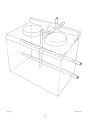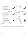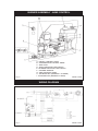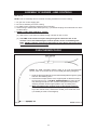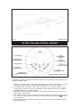
1
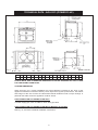
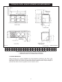
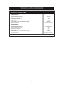
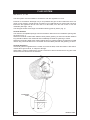
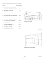
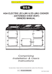
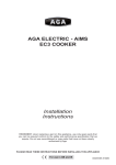
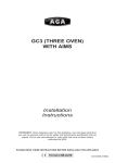
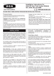
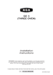
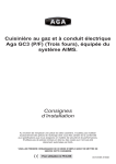
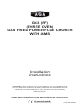
GC3 (PF)
(THREE OVEN)
GAS FIRED POWER FLUE COOKER
WITH AIMS
Installation
Instructions
REMEMBER: when replacing a part on this appliance, use only spare parts that
you can be assured conform to the safety and performance specification that we
require. Do not use reconditioned or copy parts that have not been clearly
authorised by AGA.
PLEASE READ THESE INSTRUCTIONS BEFORE INSTALLING THIS APPLIANCE
For use in GB and IE
03/10 EINS 515926
CONTENTS
SECTION
PAGE
HEALTH & SAFETY
3
INSTALLATION
4
LOCATION
4
TECHNICAL DATA - AGA GC3 P/F
5&7
TECHNICAL DATA - AGA GC3 P/F WITH MODULE
6&7
FLUE SYSTEM
8 - 11
AIR SUPPLY
12
INSTALLATION PIPES
12
BAKING OVEN BAFFLE PLATE
12
ELECTRICAL
12
BURNER ASSEMBLY - AIMS CONTROL
13
WIRING DIAGRAM
13
ASSEMBLY OF BURNER - AIMS CONTROL
14
OVEN THERMOCOUPLE
14 - 15
TO TEST THE AIMS CONTROL HANDSET
15
COMMISSIONING
16 - 17
INSTRUCTIONS
17
BURNER CONTROLS
18
2
HEALTH & SAFETY
Consumer Protection
As responsible manufacturers we take great care to make sure that our products are designed
and constructed to meet the required safety standards, when properly used and installed.
This appliance is not intended for use by persons (including children) with reduced physical,
sensory or mental capabilities, or lack of experience and knowledge, unless they have been
given supervision or instruction concerning use of the appliance by a person responsible for their
safety.
Children should be supervised to ensure that they do not play with the appliance.
IMPORTANT NOTICE: PLEASE READ THE ACCOMPANYING WARRANTY.
Any alteration that is not approved by AGA could invalidate the approval of the appliance,
operation of the warranty and could affect your statutory rights.
Important
This appliance may contain some of the materials that are indicated. It is the Users/Installers
responsibility to ensure that the necessary personal protective clothing is worn when handling,
where applicable, the pertinent parts that contain any of the listed materials that could be
interpreted as being injurious to health and safety, see below for information.
Firebricks, Fuel beds, Artificial Fuels - when handling use disposable gloves.
Fire Cement - when handling use disposable gloves.
Glues and Sealants - exercise caution - if these are still in liquid form use face mask and
disposable gloves.
Glass Yarn, Mineral Wool, Insulation Pads, Ceramic Fibre, Kerosene Oil - may be harmful if
inhaled, may be irritating to skin, eyes, nose and throat. When handling avoid inhaling and
contact with skin or eyes. Use disposable gloves, face-masks and eye protection. After handling
wash hands and other exposed parts. When disposing of the product, reduce dust with water
spray, ensure that parts are securely wrapped.
3
INSTALLATION
With specific exceptions, the installing of any type of AGA cooker is subject to the respective
directions contained in current issue of the Building Regulations. In addition, Planning
Permission may need to be obtained, which should be applied for separately. The complete
range of AGA cookers are suitable for Natural or Propane gases only and cannot be used on any
other gas. (IMPORTANT: See data plate which is situated on burner housing panel behind
top left door).
The complete cooker is floor-mounted and the space in which the appliance is to be fitted must
have the following minimum dimensions:A minimum clearance of 60mm is required above the raised insulating cover handle.
Side Clearances: A 3mm gap is required each side between the cooker top plate and adjoining
work surfaces that may be fitted, this is to allow for the safe removal of the top plate should this
be required at a later date.
Where cookers are fitted against side walls a 116mm clearance is required at the right hand side
for oven doors access. (A further 116mm is necessary, if a left hand side gas connection is
required).
If the Aga is to be installed in a brick recess, then the minimum clearance should be increased
by at least 10mm on either side, to allow for the walls not being square and also for the natural
dimensional variations found in the castings.
In addition, a minimum clearance of 1000mm must be available at the front of the cooker to
enable it to be serviced.
The wall behind the cooker must be of non-combustible material for a minimum thickness of
25mm.
NOTE: AGA GAS FIRED COOKERS ARE DELIVERED EX-WORKS UNASSEMBLED.
ASSEMBLY IS UNDERTAKEN ON SITE BY THE AUTHORISED AGA DISTRIBUTOR.
Cooker Base of Hearth
it is essential that the base or hearth on which the cooker stands should be level and be capable
of supporting the total weight of the cooker.
Model GC3 - 477 Kg
The top of the hearth must be of non-combustible material thickness of 12mm.
Tiling
When the cooker is to stand in a recess, or against a wall which is to be tiled, in no circumstances
should the tiles overlap the cooker top plate.
Installation Requirements
The installation of the cooker must be in accordance with the relevant requirements of the Gas
Safety Regulations, Building Regulations.
It should be in accordance also with any relevant requirements of the Gas Region and Local
Authority.
In your own interest, and that of safety to comply with the law, all gas appliances should be
installed by a competent person, in accordance with the relevant regulations. Failure to install
appliances correctly could lead to prosecution.
On completion, test the gas installation for tightness.
LOCATION
The location chosen for the appliance must permit the provision of a satisfactory flue and an
adequate air supply. The location must also provide adequate space for servicing and air
circulation around the cooker.
4
TECHNICAL DATA - AGA GC3 (POWER FLUE)
Fig. 1
DESN 513391B
A
B
C
D
E
F
G
H
J
K
mm 987 967 851 679 41 1330 756 1125 39
3
L
R
S
698 116 48
T
U
V
W
65 375 595 667
PLEASE NOTE: SIDE CLEARANCE DIMENSION R IS ALSO REQUIRED ON THE LH SIDE
FOR THE BAKING OVEN DOOR.
COOKER DIMENSIONS
When surveying for a cooker installation the actual clearance required for the ‘body’ of the
appliance should be increased overall by 10mm beyond the figures quoted above. This allows
safe margin to take into account the natural dimensional variations found in major castings. In
particular the width across the appliance could be critical.
GAS CONNECTION GC3 POWER FLUE ONLY
1/4” BSP supply pipe, with 1/4” BSP to 15mm fitting provided.
GAS CONNECTION GC3 POWER FLUE WITH A MODULE (IF FITTED)
See Fig. 1A, and refer to Module Installation Instructions.
5
TECHNICAL DATA - AGA GC3 (POWER FLUE) WITH MODULE
DESN 513392 B
Fig. 1A
A
B
C
D
***
E
mm 1598 889 851 679 60
F
G
H
J
I*
K
967 1330 756 1125 685 116
L
3
M
N** O**
P
698 1533 800 48
Q
R
S
T
65 375 500 595 960
* GAS SUPPLY PIPE FOR GC3 (PF) WHEN FITTED TO MODULE
** POSITION FOR GAS SUPPLY PIPE TO MODULE
*** WHEN ADJACENT TO COMBUSTIBLE MATERIAL
COOKER DIMENSIONS
When surveying for a cooker installation the actual clearance required for the ‘body’ of the
appliance should be increased overall by 10mm beyond the figures quoted above. This allows
safe margin to take into account the natural dimensional variations found in major castings. In
particular the width across the appliance recess could be critical.
6
U
TECHNICAL DATA (CONTINUED)
AGA GC3 P/F COOKER (AIMS)
NATURAL G20
MAXIMUM HEAT INPUT
Thermostat Bypass Size
Main Burner Injector
Pilot Injector
Inlet Pressure (EU COUNTRIES ONLY)
Burner Pressure
4.4 kW
110
400
7218
20mbar
10 mbar (4” w.g.)
PROPANE G31
5kW (357g/h)
65
170
4209
37mbar
25mbar (10” w.g.)
MAXIMUM HEAT INPUT
Thermostat Bypass Size
Main Burner Injector
Pilot Injector
Inlet Pressure (EU COUNTRIES ONLY)
Burner Pressure
ELECTRICAL SUPPLY: 230V 50 Hz 3A FUSED
7
FLUE SYSTEM
SEE FIGS. 2, 3, 4 & 5
The flue system must be installed in accordance with the regulations in force.
Products of combustion discharge is by a fan powered flue pipe of 50mm diameter which can
reach up to 6 metres in length through a maximum of 6 x 90Þ bends or 9 metres with one bend.
Exits from the appliance can be from rear LH or RH sides, from the rear centre or from the
underside (See Figs. 4 & 5).
The flue pipe should exit through the outside wall fixing plate by 25mm (Fig. 2).
Terminal Position
The minimum acceptable spacings from the terminal to obstructions and ventilation openings are
as shown in Fig. 3.
Where the terminal is fitted within 600mm below plastic guttering an aluminium shield 1000mm
long should be fitted to the underside and immediately beneath the guttering or eaves.
Where the terminal is fitted within 450mm below eaves or painted guttering an aluminium shield
750mm long should be fitted to the underside and immediately beneath the guttering or eaves.
Terminal Protection
A terminal guard is supplied with the cooker and must be fitted, if flue termination is less than 2
metres above ground level, or subject to damage.
When fitted, it must be positioned to provide a minimum of 50mm clearance from any part of the
terminal and be central over the terminal.
EXTERNAL
WALL
Fig. 2
DESN 511189
8
Minimum siting dimensions for Flue terminals
Position
Minimum Spacing
mm
A
Directly below an openable window,
air vent, or an other ventilation opening
300
B
Below gutter, drain/soil pipe
75
C
Below eaves
200
D
Below a balcony or car port roof
200
E
From vertical drain pipes and soil pipes
150
F
From internal or external corners
200
G
Above adjacent ground or balcony level
300
H
From surface facing the terminal
600
I
Facing terminals
1200
J
From opening (door/window)
in car port into dwelling
1200
K
Vertical from a terminal
1500
L
Horizontally from a terminal
AROUND THE HOUSE
300
DESN511052
UNDER THE CAR PORT, ETC.
Fig. 3
9
DESN511053
DESN 511190
Fig. 4
10
DOWNWARD RUNS UP TO 300mm BELOW THE APPLIANCE ARE ALLOWED, PROVIDED ONLY ONE
BEND IS USED.
DOWNWARD RUNS USING 2 BENDS ARE NOT ALLOWED.
DESN 511191
Fig. 5
11
AIR SUPPLY
Kitchen or Internal Space Air Supply
The appliance can only be installed in a room which meets ventilation regulations in force but in
any event the room must have a permanent vent of minimum free air of 36cm2.
INSTALLATION PIPES
Installation pipes should be fitted in accordance with current Gas Regulations. Pipework from the
meter to the cooker must be of adequate size, cooker connection size of 15mm Dia. On
completion test the gas installation for tightness and purge in accordance with the regulations in
force.
BAKING OVEN BAFFLE PLATE
A metal plate (with square holes) which is provided in the AGA pack MUST be positioned on the
top runners of the Baking Oven. Slide in the plate fully, until it makes contact with the back of the
oven.
This baffle is a permanent part of the Baking Oven, to regulate oven temperature.
ELECTRICAL
See Wiring Diagram (Fig. 7)
A 3 Amp 230V-50Hz fused electrical supply is required adjacent to the appliance. External wiring
to the fan unit must be installed using a 3-core heat resistant silicone sheathed cable and in
accordance with the current Wiring Regulations and any local regulations which apply.
The wiring should be completed as indicated:
The method of connection to the mains electricity supply must facilitate complete electrical
isolation of the appliance, preferably by the use of an unswitched shuttered socket outlet in
conjunction with a fused three pin plug. Alternatively, a fused double pole switch, having a
contact separation of at least 3mm in both poles serving only the appliance may be used.
12
BURNER ASSEMBLY - AIMS CONTROL
A - ON/OFF CONTROL KNOB
B - TEMPERATURE CONTROL KNOB
C - GAS COCK
D - INLET PRESSURE TEST NIPPLE
E - BURNER PRESSURE TEST NIPPLE
F - VIEWING WINDOW
G - AIMS CONTROL KNOB
H - SOLENOID N/C (NORMALLY CLOSED)
I - SOLENOID N/O (NORMALLY OPEN)
Fig. 6
DESN 515490
WIRING DIAGRAM
Fig. 7
DESN 515493
13
ASSEMBLY OF BURNER - AIMS CONTROLS
SEE FIG. 6
NOTE: Prior to assembly remove controls mounting bracket from burner housing.
1.
2.
3.
4.
Fit gas cock to inlet supply pipe.
Fit burner assembly to burner housing.
Fix AIMS control mounting bracket to burner housing.
Attach wiring to AIMS control board (See Fig. 7) and solenoid plugs onto solenoids. Fix wires
to cable clamp.
5. WHEN FITTING AIMS CONTROL COVER:
(a) Take care to route solenoid cables through notches at rear of cover.
(b) The AIMS control knob must pass freely through the clearance hole in the
controls cover. Avoid distorting the control spindle, as this could damage the
PCB. (NOTE: It may be necessary to adjust the fit of the burner housing to front
plate, to fit controls cover correctly).
OVEN THERMOCOUPLE
NOTE: On AIMS controlled cookers, there is an oven thermocouple
sensor, which is connected to the control PCB (See Wiring Diagram).
1. Feed the thermocouple sensor and thermostat phial through the guide
tube into the Roasting Oven.
2. Fit the thermocouple sensor to the support plate so that the sensing
tip is as show in Fig. 9. DO NOT OVERTIGHTEN the clamp as this
may damage the sensor. Also, fit thermostat phial through hole in
clamping bracket. Screw support plate to top of roasting oven.
3. When assembling the controls cover to the burner housing:Ensure that the thermocouple sensor goes through the notch in the
top of the controls cover, and that the sealed pot is inside the cover
(i.e. sealed pot must not be trapped).
Fig. 8
DESN 515277 A
14
DESN 515480
Fig. 9
TO TEST THE AIMS CONTROL HANDSET
Fig. 10
DESN 515481
Handset to Base Unit Signal Check/Language Selection
Complete the following procedure to check the handset is communicating with the base unit and
to select language option.
1. Switch on the power supply to the cooker. Immediately, switch the control knob on the base
unit back and forth between manual and AIMS setting until the blue neon flashes.
2. Immediately after neon starts to flash press and hold the + and - buttons together on the
handset until the blue neon goes out completely (handset display will briefly say ‘SERIAL
NUMBER FOUND’), then release buttons.
3. If the neon does not extinguish completely, but continues to flash with a faint output, then
repeat steps 1 and 2 above.
4. When the connection has been made, the screen will display the language options, use the
+ or - buttons to scroll through the options to the desired language, then press
button to
confirm selection.
5. If the language options need to be changed at any time then the whole procedure must be
repeated from step 1.
15
COMMISSIONING
CAUTION: BEFORE LIGHTING: ENSURE KNOB (A) IS IN THE OFF POSITION (SEE FIG.
12). ALSO ENSURE GAS SUPPLY TO COOKER IS ON, AND THE GAS SERVICE COCK (C)
IS IN THE ON POSITION (SEE FIG. 6), AND THE ELECTRICAL SUPPLY TO THE AGA IS
SWITCHED ON.
LIGHTING PROCEDURE: SEE FIGS. 11 - 17.
1. The main burner gas flow is set with the ‘temperature’ knob (B) (See Fig. 11). First, ensure
both knobs are turned fully clockwise. Knob (A) to the OFF position and knob (B) to the
minimum setting (thin end of the white band).
2. Turn ON/OFF knob (A) slightly anti-clockwise towards the IGNITION position (
) until
reaching stop, press down and hold for 5 seconds (gas flows only to the pilot burner). (See
Fig. 13).
3. Continue pressing down knob (A) while turning further anti-clockwise to the PILOT position
(this activates the piezo), continue to hold down for 10 seconds after pilot burner has
been lit. (If the pilot does not light, steps 2 and 3 can be repeated). (See Fig. 14).
4. Upon lighting, release knob and turn further anti-clockwise to the ON position (large flame
symbol) (See Fig. 15). Pilot gas flows and mains gas flows according to the temperature
setting (knob B).
5. Turn the temperature knob (B) slightly anti-clockwise into the white band (LOW FIRE
position). Leave in the low fire position for at least 30 minutes (See Fig. 16).
NOTE: ‘LOW FIRE’ position is attained by turning knob (B) gradually into the white band, until
SMALL FLAME is observed through viewing window (F). (See Fig. 6).
6. After 30 minutes rotate control knob (B) anti-clockwise to the mid-position of the green band
for normal running (See Fig. 17).
NOTE: After several hours the heat indicator should be within the black band on the AIMS
handset ‘INFORMATION SCREEN. It may be necessary to adjust the control knob in the green
band to achieve this, allow the cooker to stabilise for at least 4 hours before attempting any
further adjustment.
When the cooker is lit from cold, moisture may form on the enamel which should be wiped off to
prevent staining.
IF THE FLAME HAS EXTINGUISHED FOR WHATEVER REASON, WAIT THREE MINUTES
(MINIMUM) BEFORE RE-LIGHTING.
6. Check the inlet gas pressure is as indicated on the data plate (See Fig. 6).
(a)
Turn knob (A) to the OFF position (Fig. 12). Unscrew the inlet pressure test nipple
plug (D), and fit pressure gauge. Light the burner, turn knob (A) to the ON position
(Fig. 15) and knob (B) to the mid-position of the green band (Fig. 17).
(b)
Check inlet pressure correctly corresponds to the data plate.
(c)
Check that the gas pressure is unaffected when other gas appliances are used.
(d)
Turn knob (A) to OFF position. Remove the pressure gauge and replace test nipple
plug (screw plug back in, but take care not to overtighten).
(e)
Relight burner as steps 1 to 6 and check pressure test nipple for gas tightness.
16
COMMISSIONING (CONTINUED)
7.
Check burner pressure as follows:Repeat instruction 6 on completely cold cooker with the pressure gauge fitted to the burner
pressure test nipple (E). (See Fig. 6). Check that the burner pressure correctly
corresponds with the table marked ‘TECHNICAL DATA ‘, (page 7).
NOTE: IF FOR ANY REASON A GAS RATE CHECK IS REQUIRED. TURN OFF ALL OTHER
APPLIANCES USING GAS AND USING THE GAS METER TEST DIAL AND STOPWATCH.
CHECK THAT THE MAXIMUM GAS INPUT TO THE APPLIANCE IS AS INDICATED ON THE
DATA PLATE.
Once the correct setting has been confirmed, the heat control will operate automatically to
maintain the cooker at full temperature.
NOTE: REMEMBER TO NOTE THE SETTING POSITION IF TURNING OFF THE COOKER.
INSTRUCTIONS
Hand these and the operating instructions to the User for retention and instruct in the safe
operation of the appliance.
Finally advise the User that, for continued efficient and safe operation of the appliance it is
important that adequate servicing is carried out at regular intervals recommended by the AGA
Distributor or local Gas Region.
17
BURNER CONTROLS
Fig. 11
Fig. 12
Fig. 13
Fig. 14
Fig. 15
Fig. 16
Fig. 17
DESN 513393
18
19
For further advice or information contact
your local AGA Specialist
With AGA’s policy of continuous product
improvement, the Company reserves the right to
change specifications and make modifications to
the appliance described and illustrated at any time
Manufactured by
AGA
Station Road
Ketley Telford
Shropshire TF1 5AQ
England
www.aga-web.co.uk
www.agacookshop.co.uk
www.agalinks.com
20