1
1
: '10/Jun/18
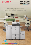
INSTALLATION MANUAL
CODE: 00ZMXM503/I3E
DIGITAL MULTIFUNCTIONAL SYSTEM
MX-M283N
MX-M363N/U
MX-M453N/U
MX-M503N/U
MX-M282N/M362N
MODEL MX-M452N/M502N
1
CONTENTS
CONFIGURATION
[16] MX-FWX1. . . . . . . . . . . . . . . . . . . . 16-1
[1]
MX-M283N/M363N/M363U/
M453N/M453U/M503N/M503U/
M282N/M362N/M452N/M502N . . . . 1-1
[17] MX-EBX3 . . . . . . . . . . . . . . . . . . . . 17-1
[2]
MX-DEX8/DEX9 . . . . . . . . . . . . . . . . 2-1
[19] MX-PUX1 . . . . . . . . . . . . . . . . . . . . 19-1
[3]
MX-LCX1 . . . . . . . . . . . . . . . . . . . . . 3-1
[20] MX-SMX3. . . . . . . . . . . . . . . . . . . . 20-1
[4]
MX-FNX9 . . . . . . . . . . . . . . . . . . . . . 4-1
[21] AR-PF1 . . . . . . . . . . . . . . . . . . . . . 21-1
[5]
MX-PNX1 . . . . . . . . . . . . . . . . . . . . . 5-1
[6]
MX-RBX3 . . . . . . . . . . . . . . . . . . . . . 6-1
[22] MX-FR14U/FR14/FR15U/FR15/
FR24U . . . . . . . . . . . . . . . . . . . . . . 22-1
[7]
MX-FN10 . . . . . . . . . . . . . . . . . . . . . 7-1
[8]
MX-PNX5A/B/C/D . . . . . . . . . . . . . . 8-1
[9]
MX-FN11 . . . . . . . . . . . . . . . . . . . . . 9-1
1
[10] MX-PNX6A/B/C/D . . . . . . . . . . . . . 10-1
[11] MX-TRX2 . . . . . . . . . . . . . . . . . . . . 11-1
[12] MX-FXX2 . . . . . . . . . . . . . . . . . . . . 12-1
[13] AR-SU1 . . . . . . . . . . . . . . . . . . . . . 13-1
[14] MX-PB10 . . . . . . . . . . . . . . . . . . . . 14-1
[18] MX-PKX1 . . . . . . . . . . . . . . . . . . . . 18-1
1
[23] MX-KBX2 . . . . . . . . . . . . . . . . . . . . 23-1
[24] MX-AMX1. . . . . . . . . . . . . . . . . . . . 24-1
[25] MX-AMX2. . . . . . . . . . . . . . . . . . . . 25-1
[26] MX-AMX3. . . . . . . . . . . . . . . . . . . . 26-1
[27] Dehumidifying heater . . . . . . . . . . . 27-1
[28] MX-RP11 . . . . . . . . . . . . . . . . . . . . 28-1
1
[29] MX-PC11/XB13
* Refer to the MX-PC11
(00ZMXPC11/A1J) service manual
[15] MX-PB11 . . . . . . . . . . . . . . . . . . . . 15-1
Parts marked with " " are important for maintaining the safety of the set. Be sure to replace these parts with
specified ones for maintaining the safety and performance of the set.
SHARP CORPORATION
This document has been published to be used
for after sales service only.
The contents are subject to change without notice.
1
: '10/Jun/18
CONTENTS
CONFIGURATION
1. Main unit and option. . . . . . . . . . . . . . . . . . . . . . .i
2. Main unit configuration. . . . . . . . . . . . . . . . . . . . ii
3. Combination of options . . . . . . . . . . . . . . . . . . . ii
[1]
1
MX-M283N/M363N/M363U/M453N/M453U/M503N/
M503U/M282N/M362N/M452N/M502N
1. Installing (use) conditions . . . . . . . . . . . . . . . 1-1
2. Transit and delivery . . . . . . . . . . . . . . . . . . . . 1-3
3. Unpacking . . . . . . . . . . . . . . . . . . . . . . . . . . . 1-3
4. Installation . . . . . . . . . . . . . . . . . . . . . . . . . . . 1-4
[2]
MX-DEX8/DEX9
1. Unpacking . . . . . . . . . . . . . . . . . . . . . . . . . . . 2-1
2. Installation . . . . . . . . . . . . . . . . . . . . . . . . . . . 2-1
[3]
MX-LCX1
1. Unpacking . . . . . . . . . . . . . . . . . . . . . . . . . . . 3-1
2. Installation . . . . . . . . . . . . . . . . . . . . . . . . . . . 3-1
[4]
MX-FNX9
1. Unpacking . . . . . . . . . . . . . . . . . . . . . . . . . . . 4-1
2. Installation . . . . . . . . . . . . . . . . . . . . . . . . . . . 4-2
[5]
MX-PNX1
1. Unpacking . . . . . . . . . . . . . . . . . . . . . . . . . . . 5-1
2. Installation . . . . . . . . . . . . . . . . . . . . . . . . . . . 5-1
[6]
MX-RBX3
1. Unpacking . . . . . . . . . . . . . . . . . . . . . . . . . . . 6-1
2. Installation . . . . . . . . . . . . . . . . . . . . . . . . . . . 6-1
[7]
[8]
[9]
MX-FN10
1. Unpacking . . . . . . . . . . . . . . . . . . . . . . . . . . . 7-1
2. Installation . . . . . . . . . . . . . . . . . . . . . . . . . . . 7-2
MX-PNX5A/B/C/D
1. Unpacking . . . . . . . . . . . . . . . . . . . . . . . . . . . 8-1
2. Installation . . . . . . . . . . . . . . . . . . . . . . . . . . . 8-1
MX-FN11
1. Unpacking . . . . . . . . . . . . . . . . . . . . . . . . . . . 9-1
2. Installation . . . . . . . . . . . . . . . . . . . . . . . . . . . 9-3
[10] MX-PNX6A/B/C/D
1. Unpacking . . . . . . . . . . . . . . . . . . . . . . . . . . 10-1
2. Installation . . . . . . . . . . . . . . . . . . . . . . . . . . 10-2
[11] MX-TRX2
1. Unpacking . . . . . . . . . . . . . . . . . . . . . . . . . . .11-1
2. Installation . . . . . . . . . . . . . . . . . . . . . . . . . . .11-1
[12] MX-FXX2
1. Unpacking . . . . . . . . . . . . . . . . . . . . . . . . . . 12-1
2. Installation . . . . . . . . . . . . . . . . . . . . . . . . . . 12-1
[13] AR-SU1
1. Unpacking . . . . . . . . . . . . . . . . . . . . . . . . . . 13-1
2. Installation . . . . . . . . . . . . . . . . . . . . . . . . . . 13-1
[14] MX-PB10
1. Unpacking . . . . . . . . . . . . . . . . . . . . . . . . . . 14-1
2. Installation . . . . . . . . . . . . . . . . . . . . . . . . . . 14-1
[15] MX-PB11
1. Unpacking . . . . . . . . . . . . . . . . . . . . . . . . . . 15-1
2. Installation . . . . . . . . . . . . . . . . . . . . . . . . . . 15-1
[16] MX-FWX1
1. Unpacking . . . . . . . . . . . . . . . . . . . . . . . . . . 16-1
2. Installation . . . . . . . . . . . . . . . . . . . . . . . . . . 16-1
[17] MX-EBX3
1. Unpacking . . . . . . . . . . . . . . . . . . . . . . . . . . 17-1
2. Installation . . . . . . . . . . . . . . . . . . . . . . . . . . 17-2
[18] MX-PKX1
1. Unpacking . . . . . . . . . . . . . . . . . . . . . . . . . . 18-1
2. Installation . . . . . . . . . . . . . . . . . . . . . . . . . . 18-1
[19] MX-PUX1
1. Unpacking . . . . . . . . . . . . . . . . . . . . . . . . . . 19-1
2. Installation . . . . . . . . . . . . . . . . . . . . . . . . . . 19-1
[20] MX-SMX3
1. Unpacking . . . . . . . . . . . . . . . . . . . . . . . . . . 20-1
2. Installation . . . . . . . . . . . . . . . . . . . . . . . . . . 20-1
[21] AR-PF1
1. Unpacking . . . . . . . . . . . . . . . . . . . . . . . . . . 21-1
2. Installation . . . . . . . . . . . . . . . . . . . . . . . . . . 21-1
[22] MX-FR14U/FR14/FR15U/FR15/FR24U
1. Unpacking . . . . . . . . . . . . . . . . . . . . . . . . . . 22-1
2. Installation . . . . . . . . . . . . . . . . . . . . . . . . . . 22-1
1
[23] MX-KBX2
1. Unpacking . . . . . . . . . . . . . . . . . . . . . . . . . . 23-1
2. Installation . . . . . . . . . . . . . . . . . . . . . . . . . . 23-1
[24] MX-AMX1
1. Unpacking . . . . . . . . . . . . . . . . . . . . . . . . . . 24-1
2. Installation . . . . . . . . . . . . . . . . . . . . . . . . . . 24-1
[25] MX-AMX2
1. Unpacking . . . . . . . . . . . . . . . . . . . . . . . . . . 25-1
2. Installation . . . . . . . . . . . . . . . . . . . . . . . . . . 25-1
[26] MX-AMX3
1. Unpacking . . . . . . . . . . . . . . . . . . . . . . . . . . 26-1
2. Installation . . . . . . . . . . . . . . . . . . . . . . . . . . 26-1
[27] Dehumidifying heater
1. Parts included . . . . . . . . . . . . . . . . . . . . . . . 27-1
2. Installation . . . . . . . . . . . . . . . . . . . . . . . . . . 27-1
[28] MX-RP11
1. Unpacking . . . . . . . . . . . . . . . . . . . . . . . 28-1
2.
Installation . . . . . . . . . . . . . . . . . . . . . . . 28-1
[29] MX-PC11/XB13
* Refer to the MX-PC11 (00ZMXPC11/A1J)
service manual
1
1
: '10/Jun/18
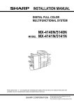
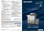
CONFIGURATION
MX-M503N
Service Manual
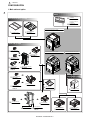
1. Main unit and option
1
Other
PLASMACLUSTER ION
GENERATOR
43 MX-PC11
Document reading system
PLASMACLUSTER ION
GENERATOR
MOUNTING KIT
44 MX-XB13
DIGITAL MULTIFUNCTIONAL SYSTEM
MX-M282N/M362N/M452N/M502N
REVERSING SINGLE
PASS FEEDER
DOCUMENT COVER
1 MX-VRX1
2 MX-RP11
Paper exit system
STAPLE CARTRIDGE
12 MX-SCX1
DIGITAL MULTIFUNCTIONAL SYSTEM
DIGITAL MULTIFUNCTIONAL SYSTEM
MX-M283N/M363N/M453N/M503N
MX-M363U/M453U/M503U
PAPER PASS UNIT
8 MX-RBX3
STAPLE CARTRIDGE
13 AR-SC3 (For saddle)
PUNCH MODULE
11 MX-PNX5
SADDLE STITCH FINISHER
9 MX-FN10
A/B/C/D
Paper feed system
STAPLE CARTRIDGE
12 MX-SCX1
FINISHER
PUNCH MODULE
10 MX-PNX1
7 MX-FNX9
EXIT TRAY UNIT
6 MX-TRX2
A/B/C/D
LARGE CAPACITY TRAY
5 MX-LCX1
STAPLE CARTRIDGE
16 AR-SC2
PAPER PASS UNIT
8 MX-RBX3
FINISHER
14 MX-FN11
PUNCH MODULE
15 MX-PNX6
A/B/C/D
MX-M503N CONFIGURATION - i
STAND/1 x 500 SHEET
PAPER DRAWER
3 MX-DEX8
STAND/2 x 500 SHEET
PAPER DRAWER
4 MX-DEX9
1
: '10/Jun/18
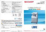
1
Printer expansion
PRINTER EXPANSION KIT
WITHOUT HDD
(For U model only)
17 MX-PB10
Image send expansion
PRINTER EXPANSION KIT
WITH HDD
(For U model only)
18 MX-PB11
PS3 EXPANSION KIT
19 MX-PKX1
FACSIMILE
EXPANSION KIT
BARCODE FONT KIT
21 AR-PF1
XPS EXPANSION KIT
20 MX-PUX1
30 MX-FR14
DATA SECURITY KIT
(For the machine
without HDD installed)
DATA SECURITY KIT
(For the machine
without HDD installed)
32 MX-FR15
31 MX-FR15U
STAMP CARTRIDGE
26 MX-EBX3
APPLICATION
INTEGRATION MODULE
27 MX-AMX1
ENHANCED COMPRESSION KIT
(For N model only)
NETWORK SCANNER
EXPANSION KIT (For U model only)
28 MX-NSX1
Application/Solution
DATA SECURITY KIT
(For the machine
with HDD installed)
29 MX-FR14U
25 MX-FWX1
24 AR-SV1
Authentication/Security
DATA SECURITY KIT
(For the machine
with HDD installed)
INTERNET FAX
EXPANSION KIT
STAMP UNIT
23 AR-SU1
22 MX-FXX2
SHARPDESK
50 LICENSE KIT
SHARPDESK
1 LICENSE KIT
APPLICATION
COMMUNICATION MODULE
39 MX-AMX2
37 MX-US50
34 MX-USX1
SHARPDESK
5 LICENSE KIT
SHARPDESK
100 LICENSE KIT
35 MX-USX5
KEYBOARD (For N model only)
41 MX-KBX2
EXTERNAL
ACCOUNT MODULE
40 MX-AMX3
38 MX-USA0
SHARPDESK
10 LICENSE KIT
DATA SECURITY KIT
33 MX-FR24U
36 MX-US10
Memory
EXPANSION
MEMORY BOARD
42 MX-SMX3
2. Main unit configuration
1
1
Copier
PCL printer
PS printer
Main body LCD
FAX
Scanner
Filing (Print hold function)
HDD
RSPF/DSPF/OC
Automatic duplex
Security
Internet Fax
MX-M363N/MX-M453N/
MX-M503N
STD
STD
OPT*1
COLOR WVGA 8.5"
OPT
STD
STD
STD
DSPF
STD
OPT*1
OPT*1
MX-M283N
STD
STD
OPT*1
COLOR WVGA 8.5"
OPT
STD
STD
STD
RSPF
STD
OPT*1
OPT*1
MX-M363U/MX-M453U/
MX-M503U
STD
OPT*1
OPT*1
MONOCHROME HVGA 8.1"
OPT
OPT*1
OPT*1
OPT*1
RSPF
STD
OPT*1
OPT*1
MX-M282N/MX-M362N/
MX-M452N/MX-M502N
STD
STD
OPT*1
COLOR WVGA 7"
OPT
STD
STD
STD
RSPF or OC
STD
OPT*1
OPT*1
STD: Standard provision. OPT: Option. OPT*1: Product key target.
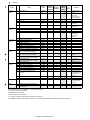
3. Combination of options
1
1
Section
Document
reading
system
Paper feed
system
Paper exit
system
Model
name
Name
1
2
DOCUMENT COVER
REVERSING SINGLE PASS FEEDER
MX-VRX1
MX-RP11
3
4
5
6
7
8
9
10
STAND/1 x 500 SHEET PAPER DRAWER
STAND/2 x 500 SHEET PAPER DRAWER
LARGE CAPACITY TRAY
EXIT TRAY UNIT
FINISHER
PAPER PASS UNIT
SADDLE STITCH FINISHER
PUNCH MODULE
MX-DEX8
MX-DEX9
MX-LCX1
MX-TRX2
MX-FNX9
MX-RBX3
MX-FN10
MX-PNX1A/
B/C/D
MX-M283N
MX-M363N
MX-M453N
MX-M503N
—
STD/—*5
—
STD
MX-M282N
MX-M362N
MX-M452N
MX-M502N
{
{
{
{
{
{
{
{
{
{
{
{
{
{
{
{
{
{
MX-M363U
MX-M453U
MX-M503U
{
{
{
{
{
{
{
{
MX-M503N CONFIGURATION - ii
Product
key
target
Remarks
A4
Inner finisher
For inner finisher
1
1
: '10/Jun/18
Paper exit
system
Printer
expansion
Image send
expansion
Authentication/
Security
{
{
{
{
{
{
{
{
{
{
{
{
{
{
{
{
MX-PB10
MX-PB11
MX-PKX1
MX-PUX1
—
STD
{
{*3
{
{
{
{*3
—
STD
{
{*3
{
{
{
{
BARCODE FONT KIT
FACSIMILE EXPANSION KIT
STAMP UNIT
STAMP CARTRIDGE
INTERNET FAX EXPANSION KIT
ENHANCED COMPRESSION KIT
APPLICATION INTEGRATION MODULE
NETWORK SCANNER EXPANSION KIT
DATA SECURITY KIT
(For the machine with HDD installed)
DATA SECURITY KIT
(For the machine with HDD installed)
DATA SECURITY KIT
(For the machine without HDD installed)
DATA SECURITY KIT
(For the machine without HDD installed)
DATA SECURITY KIT
SHARPDESK 1 LICENSE KIT
SHARPDESK 5 LICENSE KIT
SHARPDESK 10 LICENSE KIT
SHARPDESK 50 LICENSE KIT
SHARPDESK 100 LICENSE KIT
APPLICATION COMMUNICATION
MODULE
AR-PF1
MX-FXX2
AR-SU1
AR-SV1
MX-FWX1
MX-EBX3
MX-AMX1
MX-NSX1
MX-FR14U
{
{*1
{
{
{
{
{
STD
{
{
{*1
{
{
{*4
—
{*4
{
{*4
{
{*1
{
{
{
{
{
STD
—
{
MX-FR14
{
{*4
—
{
MX-FR15U
—
{
—
{
MX-FR15
—
{
—
{
MX-FR24U
MX-USX1
MX-USX5
MX-US10
MX-US50
MX-USA0
MX-AMX2
—
{
{
{
{
{
STD/{*2
—
{
{
{
{
{
{*4
{
{
{
{
{
{
STD/{*2
{
40
41
42
EXTERNAL ACCOUNT MODULE
KEYBOARD
EXPANSION MEMORY BOARD
MX-AMX3
MX-KBX2
MX-SMX3
{
STD/{*2
{
{*4
—
{
{
—
{
{
43
44
PLASMACLUSTER ION GENERATOR
PLASMACLUSTER ION GENERATOR
MOUNTING KIT
MX-PC11
MX-XB13
{
{
{
{
{
{
{
{
11
PUNCH MODULE
12
STAPLE CARTRIDGE
13
14
15
STAPLE CARTRIDGE
FINISHER
PUNCH MODULE
16
STAPLE CARTRIDGE
AR-SC3
MX-FN11
MX-PNX6A/
B/C/D
AR-SC2
17
18
19
20
PRINTER EXPANSION KIT WITHOUT HDD
PRINTER EXPANSION KIT WITH HDD
PS3 EXPANSION KIT
XPS EXPANSION KIT
21
22
23
24
25
26
27
28
29
31
32
1
Application/
Solution
Memory
1
Others
Model
name
Name
30
1
MX-M283N
MX-M363N
MX-M453N
MX-M503N
{
MX-M282N
MX-M362N
MX-M452N
MX-M502N
{
Section
33
34
35
36
37
38
39
MX-PNX5A/
B/C/D
MX-SCX1
MX-M363U
MX-M453U
MX-M503U
Product
key
target
For saddle stitch
finisher
For finisher
(MX-FNX9)/
For saddle stitch
finisher (MX-FN10)
For saddle
For finisher
(MX-FN11)
For finisher
(MX-FN11)
{
{
{
{
The expansion
memory board
(MX-SMX3) is
required.
Commercial version
Authentication
version
Commercial version
Authentication
version
Commercial version
For North America,
the SharpOSA Utility
CD-ROM is not
provided.
1GB (Required when
the XPS expansion
kit is used.)
STD: Standard provision. {: Installable. —: Cannot be connected.
*1: No support for some destinations.
*2: Standard for North America.
*3: Memory expansion are required.
*4: The printer expansion kit with hard drive (MX-PB11) is required.
*5: MX-M283N includes this as standard equipment. Other models of MX-M283N includes DSPF as standard equipment.
MX-M503N CONFIGURATION - iii
Remarks
1
: '10/Jun/18
[1] MX-M283N/M363N/M363U/
M453N/M453U/M503N/M503U/
M282N/M362N/M452N/M502N
MX-M503N
1
(3)
Power Manual
frequency, waveform
Service
The frequency must be within the range of the specified frequency
±2%. If power waveform is deformed, a trouble may occur.
(4)
Safety
Be sure to properly ground the machine.
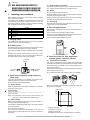
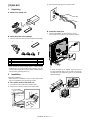
1.
Installing (use) conditions
Before installing the machine, check that the following installing
(use) conditions are satisfied.
If the installing (use) conditions are not satisfied, the machine may
not display full performances, resulting in troubles. It may also
cause safety problems. Therefore, be sure to arrange the installing
(use) conditions before setting up the machine.
No.
1
2
3
4
5
Content
Bringing space
Installing space
Power source (Capacity, fluctuation, safety)
Floor strength
Direct rays of the sun, dust, temperature, humidity, gases,
chemicals
Grounding (earth connection) must be performed before inserting
the power plug into the power outlet.
When disconnecting the earth connection, be sure to disconnect
the power plug from the power outlet in advance.
(5)
Power plug
Check the shape of the power plug of the machine, and insert it into
a power outlet of the acceptable shape.
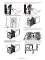
D. Floor strength and level
This machine is considerably heavy and becomes heavier with an
option installed.
The floor must be strong enough for assuring safety.
If the unit is not horizontally installed, the toner density control is not
performed normally, degrading the copy quality.
If not, color shift or image distortion may occur.
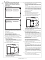
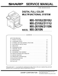
A. Bringing space
For installation of a large size machine, be sure to check that the
door size is wide enough before bringing in.
B. Installing space
The following space must be provided around the machine in order
to assure machine performances and proper operations.
If any option is installed, provide the additional space for installing
it.
Adequate space must be provide behind the machine for proper
ventilation heat and dust. If not, the machine cannot exhibit functions against heat and dust, causing some troubles.
11-13/16"
(30cm)
11-13/16"
(30cm)
E. Direct rays of the sun, dust, temperature,
humidity, gasses, chemicals, vibration
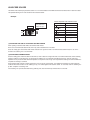
(1)
Temperature and humidity
This machine is designed to perform properly under the specified
temperature and humidity. If the temperature and humidity exceeds
the specified range, the machine may not operate properly and or
cause equipment failure.
17-23/32"
(45cm)
Especially when the humidity is too high, paper absorbs humidity to
cause a paper jam or dirty copy.
Do not install the machine near a heater, a cooler, or a humidifier.
C. Power source (Capacity, voltage, frequency,
safety, plug)
If the power specifications are not satisfied, the machine cannot
exhibit full performances and may cause safety trouble.
Strictly observe the following specifications.
(1)
Power capacity
Check that the following power capacity is satisfied. If not, additionally provide a power source.
1
Dew may be formed inside the machine to cause a trouble. Use
enough care for ventilation.
Current capacity
Humidity㧔RH㧕
100V: 15A or more
85%
200V: 10A or more
60%
NOTE: Check the shape of the power plug of the machine, and
insert it into a power outlet of the acceptable shape.
(2)
Power voltage
Measure the voltage during copying to check that the voltage is in
the range of the specified voltage ±10%.
If the voltage is outside the specified range, use thicker lead wires
to reduce impedance.
(An electrical work is required.)
Use of a step-up transformer is also available. In this case, the
capacity must be great enough for the max. power consumption of
the machine.
20%
• Working environment
Temperature: 10 to 35°C
Humidity: 20 to 85% RH
Atmospheric pressure: 590 to 1013hPa (altitude: 0 to 2000 m)
MX-M503N MX-M283N/M363N/M363U/M453N/M453U/M503N/M503U/M282N/M362N/M452N/M502N 1 – 1
(2)
Dust
F. Note for handling PWB and electronic parts
If dust enters the machine, it may cause dirty copy and a paper
jam, resulting in a shortened lifetime.
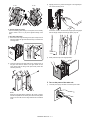
(3)
When handling the PWB and the electronic parts, be sure to
observe the following precautions in order to prevent against damage by static electricity.
1)
When in transit or storing, put the parts in an anti-static bag or
an anti-static case and do not touch them with bare hands.
2)
When and after removing the parts from an anti-static bag
(case), use an earth band as shown below:
Direct rays of the sun
If the machine is installed under the rays of the sun, the exterior of
the machine may be discolored and abnormal copies may be produced.
• Put an earth band to your arm, and connect it to the
machine.
(4)
Gases and chemicals
Do not install the machine at a place where there are gases and
chemicals. Especially be careful to avoid installation near a diazotype copier, which produces ammonium gas.
Copy quality may be adversely affected and a trouble may be
caused.
(5)
Vibration
Avoid installation near a machine which produces vibrations.
If vibrations are applied to the copier machine, copy images may be
deflected and a trouble may be caused.
• When repairing or replacing an electronic part, perform the
procedure on an anti-static mat.
MX-M503N MX-M283N/M363N/M363U/M453N/M453U/M503N/M503U/M282N/M362N/M452N/M502N 1 – 2
1
: '10/Jun/18
G. Note for handling the drum unit, the transfer
unit, the developing unit, and the fusing unit
When handling the OPC drum unit, the transfer unit, and the developing unit, strictly observe the following items.
If these items are neglected, a trouble may be generated in the
copy and print image quality.
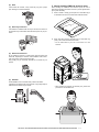
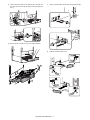
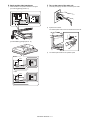
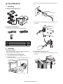
3.
Unpacking
A. Unpacking procedure
1)
Remove the PP band.
2)
Remove the internal packing pads with the machine.
(Drum unit)
1)
Avoid working at a place with strong lights.
2)
Do not expose the OPC drum to lights including interior lights
for a long time.
3)
When the OPC drum is removed from the machine, cover it
with light blocking material. (When using paper, use about 10
sheets of paper to cover it.)
4)
Be careful not to attach fingerprints, oil, grease, or other foreign material on the OPC drum surface.
(Transfer unit)
1)
Be careful not to attach fingerprints, oil, grease, or other foreign material on the transfer roller.
(Developing unit)
1)
Be careful not to attach fingerprints, oil, grease, or other foreign material on the developing unit.
(Fusing unit)
1)
Be careful not to put fingerprints, oil, grease, or other foreign
material on the fusing roller and the external heating belt.
2)
Do not leave the fusing roller in contact state for a long time.
2.
No.
1
2
Transit and delivery
Content
Implements, facility,
and man power
Delivery
Method
Use a forklift. (If no forklift is available,
manpower of two persons is required.)
Transit must be made in packed condition.
A. Implements, facility, and manpower
B. Removal of the fixing tape, protection material
and parts packed together
• MX-M283N/M363N/M363U/M453N/M453U/M503N/M503U
It is recommendable to use a forklift for bringing in the machine for
safety.
If no forklift is available, man-power of two persons is required. The
machine is considerably heavy, and requires safety precautions for
delivery and installation.
Transit of the machine must be made in packed condition to the
installing place.
Since the hard disk drive is built in the machine, use care not to
exert vibrations or shocks to the machine when in transit.
B. Delivery
Remove the packing materials prior to installation in the office environment.
MX-M503N MX-M283N/M363N/M363U/M453N/M453U/M503N/M503U/M282N/M362N/M452N/M502N 1 – 3
1
: '10/Jun/18
1
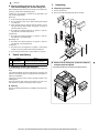
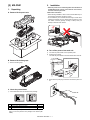
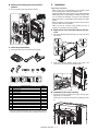
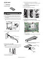
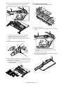
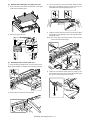
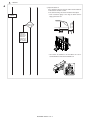
4.
• MX-M282N/M362N/M452N/M502N
1
Installation
<Note before installation>
* When connecting the main unit with the optional STAND/1 X 500
SHEET PAPER DRAWER (MX-DEX8) or STAND/2 X 500
SHEET PAPER DRAWER (MX-DEX9), first unpack and install
the MX-DEX8 or MX-DEX9; then unpack the main unit and
securely place the main unit on the MX-DEX8 or MX-DEX9
before installing the main unit.
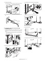
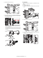
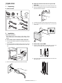
A. Lock release
(1)
Tray rotation plate lock release
1)
Pull out the tray, and remove the rotation plate fixing material
and the tray note label.
2)
Attach the removed fixing material to the position shown in the
figure for storage.
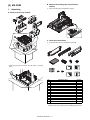
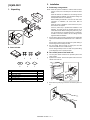
C. Check the parts packed together
1)
1
Check that all the parts are in the package.
* Expect Europe.
1
2
NO.
1
2
3
4
Parts name
Paper exit full detection actuator
Paper holding plate unit
Operation manual
Operation manual pocket
3
4
Quantity
1
1
1
1
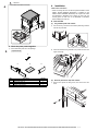
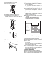
(2)
1)
Scanner (2/3 mirror unit) lock release
Remove the optical unit fixing screw, and remove the note
label.
MX-M503N MX-M283N/M363N/M363U/M453N/M453U/M503N/M503U/M282N/M362N/M452N/M502N 1 – 4
1
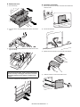
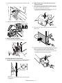
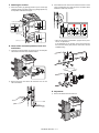
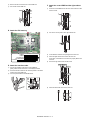
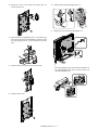
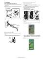
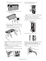
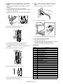
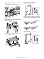
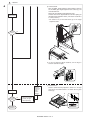
(3)
: '10/Jun/18
Removal of the fusing heat roller protector
B. Developer supply
Be careful not to put fingerprints or oil dirt on the roller surface.
Do not hold the case adjacent to the DV roller strongly.
1
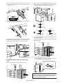
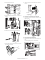
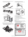
(4)
Install the paper exit cover unit
1)
Open the front cabinet, and remove the waste toner box.
2)
Remove the fixing screw of the developing unit, and pull out
the developing unit.
3)
Remove two screws. Remove the DV cover.
4)
While supplying developer from the developer supply port of
the developing unit, turn the MC gear counterclockwise by
using long-nose pliers to supply all developer to the developing
unit.
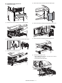
* Europe only. For except Europe, progress to the procedure of B.
* If the MX-FNX9 (Inner Finisher) or the MX-RBX3 (Interface Unit)
is installed when installing the main unit, do not install the paper
holding plate unit and the paper exit full detection actuator.
1)
2)
Install the paper exit tray, and fix the screw.
Install the paper exit tray cover.
* Before opening the developer bag, shake the bag to mix
toner and developer in the bag, and then supply developer
to the developing unit.
3)
Remove the screw, and remove the inlet cover.
Inlet cover
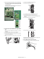
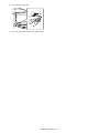
5)
Attach the DV cover to the machine.
6)
Insert the developing unit into the machine, and fix it with the
blue screw.
7)
Install the waste toner box.
* Check to confirm that the pawl is securely engaged.
MX-M503N MX-M283N/M363N/M363U/M453N/M453U/M503N/M503U/M282N/M362N/M452N/M502N 1 – 5
1
: '10/Jun/18
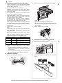
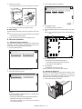
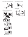
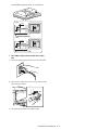
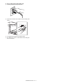
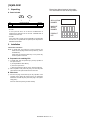
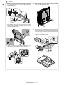
C. Toner density reference control level setting
1)
Insert the power plug into a power outlet. With the front cabinet
open, turn ON the power switch of the machine and the power
switch on the operation panel.
2)
With the front cabinet open, enter SIM 25-2.
2)
Open the front cabinet, and insert the toner cartridge slowly.
1
WARNING: Do not install the toner cartridge before completing the Toner density reference control level setting (SIM 25-2).
3)
Close the front cabinet.
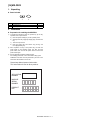
4)
After completion of the adjustment of the toner density control
reference value, insert the toner cartridge.
5)
When [EXECUTE] key is pressed, it is highlighted. The developing roller rotates, and the toner density sensor detects toner
density, and the output value is displayed.
6)
The above operation is executed for 3 minutes, and the average value of the toner density sensor detection level is set
(saved) as the reference toner density control value.
* Do not forcibly insert the toner cartridge.
When the reference toner density control adjustment operation
is completed, [EXECUTE] key returns to normal from highlight.
This makes known about whether the adjustment operation is
completed or not.
* When the machine is transported with the developing unit
removed, be sure to remove the toner cartridge. (If not, toner
may be clogged.)
Press the CA key to exit the simulation.
Keep holding the cartridge and completely insert it.
3)
Insert the cartridge securely until it locks.
NOTE:
If the operation is interrupted within 3 minutes, the adjustment
result is not reflected.
When [EXECUTE] key is pressed during rotation, the operation is stopped and [EXECUTE] key returns to the normal display.
If [EE-EU] or [EE-EL] is displayed, setting of the reference
toner density control value is not completed normally.
Error display
EE-EL
Content
EL abnormality
EE-EU
EU abnormality
EE-EC
EU abnormality
Details of content
Sensor output level less than 67, or
sensor control voltage level over 197
Sensor output level over 154, or sensor
control voltage level less than 49
Sensor output level less than 95, or
sensor control voltage level over 105
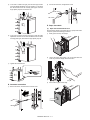
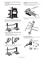
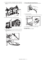
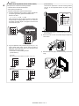
E. Installation of the paper holding plate unit
1)
Install the paper exit full detection actuator.
2)
Install the paper fixing sheet and paper fixture to the paper fixture HCT.
NOTE: When not replacing the developer, do not execute SIM252.
Only execute SIM 25-2 when replacing the Developer.
SIM 25-2 should only be run immediately after installing
new DV material.
Toner Concentration Reference Control Level Setting will
be incorrect if SIM 25-2 is performed at any other time.
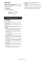
D. Install toner cartridge
1)
Shake the toner cartridge several times.
MX-M503N MX-M283N/M363N/M363U/M453N/M453U/M503N/M503U/M282N/M362N/M452N/M502N 1 – 6
1
1
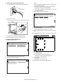
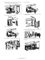
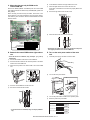
3)
: '10/Jun/18
Install the paper holding plate unit.
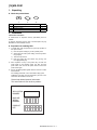
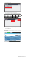
2)
Touch the [Paper Tray Settings] key.
3)
Touch the [Paper Tray Settings] key to configure the settings.
These settings specify the paper type, paper size, and functions allowed for each paper tray. When the [Tray Settings] key
is touched, a list appears showing the trays and the current
settings.
4)
Touch the [Change] key in the above screen to change the settings. The following settings can be configured.
* If the MX-FNX9 (Inner Finisher) or the MX-RBX3 (Interface
Unit) is installed when installing the main unit, do not install
the paper holding plate unit and the paper exit full detection
actuator.
1
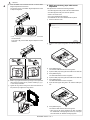
F. Installation of the operation manual pocket
1)
Install the Operation Manual storage cover to the left side of
the machine.
a)
First, insert the pawl on the lower side of the Operation
Manual pocket.
b)
Then, lift the pawl on the upper side and insert it, and slide
down to install.
* If the finisher is installed together with installation of the
machine, the Operation Manual storage cover must be
installed to the finisher.
2
Item
Type
Size
1
Feeding Approved
Job
1
(2)
1)
Description
Select the type of paper that is loaded in the tray. The
paper types that can be selected vary by paper tray.
Select the paper size from the list. The paper sizes
that can be selected vary by tray. The sizes that can
be selected may also be restricted by the paper type
selected above.
If the desired size does not appear in the list, select
[Custom Size] and directly enter the size (only for the
bypass tray).
Select the modes that can be used. If there is a
function that you do not wish to be used with the
selected tray, disable the function. When the "Type"
is other than plain paper, recycled paper, colored
paper, or a user type, [Fax] and [Internet Fax] cannot
be selected.
Tray size setup
Pull out the paper tray.
Gently pull the tray out until it stops.
G. Tray setup
(1)
If paper remains in the tray, remove it.
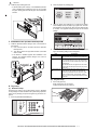
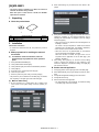
Simulation setup
Change the tray setting in the "system setting" mode. If "Disabling
of Tray Settings" has been enabled in the system settings (administrator), the tray settings (except for the bypass tray) cannot be configured.
1)
Press the [SYSTEM SETTINGS] key.
JOB STATUS
SYSTEM
SETTINGS
PRINT
READY
DATA
IMAGE SEND
LINE
DATA
HOME
LOGOUT
MX-M503N MX-M283N/M363N/M363U/M453N/M453U/M503N/M503U/M282N/M362N/M452N/M502N 1 – 7
2)
Adjust the guide plates A and B by squeezing their lock levers
and sliding them to match the vertical and horizontal dimensions of the paper to be loaded.
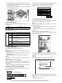
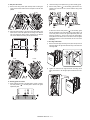
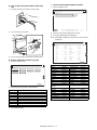
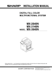
[Check with the servicing color test chart (UKOG-0317FCZZ/
UKOG-0317FC11 or UKOG-0326FCZZ/UKOG-0326FC11)]
Check to confirm that it is in the conditions shown below.
The guide plates A and B are slidable. Slide each guide plate
while squeezing its lock lever.
Serviceman chart (Color patch section)
A
Patch 7 is slightly
copied or not copied.
(2)
B
H. Specifications setup
(Note)
Used to set the specifications with SIM26 according to the customer's request.
SIM No
26
6
To customize the following items after completion of the destination
setup, change the set values.
Content
LCC paper size setting
Used to set the auditor specification mode.
Used to set the count mode of the total counter and the
maintenance counter.
Used to set YES/NO of the toner save mode
(Only in UK and Japan versions)
* For other destination versions, this setup is made by
the user program.
Used to set YES/NO of counting when non-print paper
is passed through each counter.
Used to set YES/NO of user calibration permission.
Used to set the limit number of sheets for stapling.
18
52
53
65
Before checking the printer density and gradation, be sure to execute the following jobs.
* Execute the high density image correction (Process correction)
forcibly. (SIM 44-6)
Content
Used to set the destination.
SIM No
26
2
3
5
Printer density and gradation check
If no printer option is installed to the U model, the following procedures are not required. (SIM64-5 does not operate.)
* Execute the half-tone image correction forcibly. (SIM 44-26)
(Method 1)
Execute SIM 64-5 to print the print test pattern.
Set each set value to the default and press [EXECUTE] key. The
print test pattern is printed.
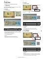
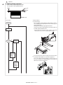
I. Image quality check
(1)
Copy density and gradation check
(Note)
Before checking the copy density and gradation, be sure to execute
the following jobs.
* Execute the high density image correction (Process correction)
forcibly. (SIM 44-6)
* Execute the half-tone image correction forcibly. (SIM 44-26)
The print density must be changed gradually from the lighter level
to the darker level. The density changing direction must not be
reversed.
(Method)
(Method 2)
Make a copy of the gray test chart (UKOG-0162FCZZ), and check
that it is proper.
Execute SIM 67-25 to print the adjustment check pattern.
Note for checking the copy mode density
To check the density, use the gray test chart (UKOG-0162FCZZ).
Set the copy density level to "Manual 3" in the Text/Printed Photo
mode (Manual).
The patch density is identical between patches or not reversed.
The patch density is changed gradually.
PRINTER CALIBRATION
Patch A or B is slightly copied.
In addition, all the picture quality adjustment settings in the user
adjustment mode must be set to the default (center).
A B C D E F G H I J K L MN O P
[Check with the gray test chart (UKOG-0162FCZZ)]
In the copy density check with the gray test chart, check to insure
the following conditions.
Patch 2 is
slightly copied.
1
2
Q (Max)
Low density
High density
SHARP gray chart
SHARP GRAY CHART
3
4
5
6
7
8
9
10
W
The print density must be changed gradually from the lighter level
to the darker level. The density changing direction must not be
reversed.
Patch 3 is copied.
Patch 1 is not copied.
Patch A or B is slightly copied.
MX-M503N MX-M283N/M363N/M363U/M453N/M453U/M503N/M503U/M282N/M362N/M452N/M502N 1 – 8
J. Function and operation check
(2)
Check that the following operations are normal.
1)
Check item list
Key-in (operation panel)
Display (operation panel)
Paper feed
Hand feed
operation
Main unit paper
tray
Desk unit paper
feed tray
Paper size detection
Originals size
Original table
detection
mode
DSPF mode
RSPF mode
DSPF/RSPF
S-S mode
operation / two
D-S mode
sided copy
S-D mode
D-D mode
Bookbinding operation
Stapling operation
Grouping operation
Sorting operation
Paper exit operation
ǂǂǂ6,08/$7,21ǂǂ12
7(67
&/26(
523(3$66:25'6(77,1*
35(6(17˖
ǂǂ1(:˖
6(7
With the desk unit installed
2)
When the finisher is installed
When the finisher is installed
When the finisher is installed
When the finisher is installed
When the exit tray unit (MX-TRX2)
is installed
Print the various setup data and the adjustment data (list) with
SIM22-6 and keep the data.
• In case of a memory trouble, if the data are not kept, all the
adjustments must be made again.
• If the data are kept, the setup values and the adjustment values
can be entered without adjustments, shortening the servicing
time.
L. Necessary works before moving the machine
If the following options are installed, remove all of them from
the machine.
• Finisher
• Large capacity tray
2)
Enter the SIM26-78 mode.
Equipped condition
K. Setup and adjustment data recording
1)
Remote operation panel function password setting
procedures
Enter the password with 10-key. (Within 5 - 8 digits)
The entered password is displayed on the column of "NEW."
To modify the entered password, use clear key to delete the
password digit by digit.
3)
Press [SET] key, and the password is set.
N. USB PORT selection
There are two USB ports; one on the front frame side and the other
on the rear frame side. Only one of them can be used at a time. Do
not connect the two USB ports simultaneously.
When shipping, the port on the front frame side is valid and the port
on the rear frame side is invalid. When using the USB port, be careful of the total current consumption not to exceed 500mA.
The valid port can be switched by changing the setting of the MFP
PWB DIP SW.
Select the valid USB port according to the user’s request.
* The default setting for SW1/SW2 is OFF.
MFP PWB DIP SW
SW 1
SW 2
OFF
OFF
OFF
ON
USB I/F
Port on the front
Port on the rear
frame side
frame side
Valid
Invalid
Invalid
Valid
Remove the following consumable parts from the machine.
• Paper
• Toner cartridges
• Development cartridge
3)
Lock the following sections.
• Scanner (Optical section)
• Paper cassette lift plate
NOTE: Since the hard disk drive is built in the machine, use care
not to exert vibrations or shocks to the machine when in
transit.
Upper side: DIP-SW1
Lower side: DIP-SW2
When tilted toward you: OFF
When tilted to the PWB side: ON
M. Remote operation panel function Enable
setting
(1)
General
To use the remote operation panel function, the password for the
remote operation panel function must be entered on the password
input menu displayed on the VNC boot screen. Note that, therefore,
the password must be set in advance to use the remote operation
panel function.
Let the user make the password, and use SIM26-78 to set it.
NOTE: For the machine which is provided with a keyboard, either
one of two USB ports can be used at a time. However, both
DIP SW1’s must be set to OFF.
Note that, if DIP SW1 is set to ON, the machine is set to the
CN update mode.
NOTE: After completion of option installation, revise all the firmware to the latest version.
MX-M503N MX-M283N/M363N/M363U/M453N/M453U/M503N/M503U/M282N/M362N/M452N/M502N 1 – 9
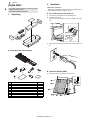
C.
Check the
packed items
Service
Manual
MX-M503N
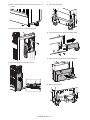
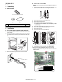
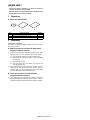
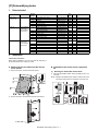
[2]
MX-DEX8/DEX9
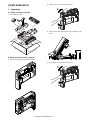
1.
1)
Check that all the items are included in the package.
Unpacking
A. Removal of the desk unit
1
No.
1
2
2.
2
Names of bundles
Right adjuster
Fixing screws (M4 x 8)
Quantity
1
4
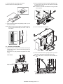
Installation
<Note before installation>
* Before starting installation, check to insure that the data lamp on
the operation panel does not light up or blink.
A. Turn off the power of the main unit
1)
Turn OFF the power switch on the operation panel.
2)
Open the front cabinet.
Turn OFF the power switch in the front cabinet of the main unit.
OFF
B. Removal of the fixing material and packing
parts
* If the connector is removed first, it may be pinched in the installing procedures. Therefore, keep it packed when unpacking the
package, and unpack it when connecting the connector to the
machine.
1)
3)
Disconnect the power plug of the main unit from the power outlet.
Remove the fixing material and packing parts.
MX-M503N MX-DEX8/DEX9 2 – 1
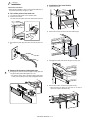
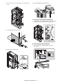
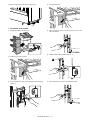
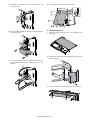
B. Installation of the adjuster
2)
1)
Install the right adjuster (package part No. 1) to the desk unit.
2)
Turn each adjuster to fix the desk unit.
Put the main unit on the desk unit.
* Use man power of four persons or more to lift the main unit.
* Place the main unit on the desk unit slowly by fitting the
external lines. Check to insure that the positioning pin on the
top of the desk unit is securely engaged in the positioning
groove of the main unit.
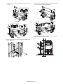
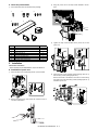
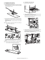
C. Connection of the main unit and the desk unit
1)
Remove the connection plate covers of the both sides of the
main unit.
3)
Remove the No. 2 paper feed tray.
2
2
1
1
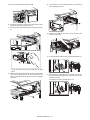
4)
Pull out the No. 3 paper feed tray until it stops.
2
1
MX-M503N MX-DEX8/DEX9 2 – 2
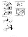
5)
Lift the connection plates on the right and left of the main unit
front side, and fix them with the fixing screws (package part
No. 2).
6)
Replace the No. 3 and No. 2 trays to the original positions.
7)
Lift the connection plates, and fix them with the fixing screws.
8)
Install the connection plate covers.
2
1
1
2
2
1
MX-M503N MX-DEX8/DEX9 2 – 3
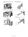
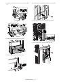
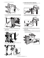
D. Release the lock
E. Connector connection
1)
Pull out each tray.
1)
Remove the screw from the back of the main unit. Remove the
connector cover.
2)
Turn and remove the fixing material, and remove the caution
sheet.
2)
Connect the connector.
3)
Attach the removed fixing material to the position shown in the
figure for storage.
3)
Split the removed connector cover along the perforated line.
4)
Install the connector cover and fix it with a screw.
NOTE:
Before turning on the power, check to insure that the fixing
material of the tray is disengaged. If the power is turned on
without disengaging the fixing material, a trouble may be
resulted.
4)
Close the cassette which was pulled out.
MX-M503N MX-DEX8/DEX9 2 – 4
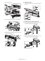
F. Turn on the power of the main unit
(Note)
1)
By pressing [LEAD] or [OFFSET] button, the following items
can be executed individually.
Insert the power plug of the main unit into the power outlet.
* [LEAD]: Print image lead edge image position adjustment
* [OFFSET]: Print image off-center adjustment
When [ALL] is selected, both of the above two items are
executed simultaneously.
4)
Select a paper feed tray to be adjusted.
ǂǂǂ6,08/$7,21ǂǂ12
7(67
&/26(
$872,0$*(326,7,21$'-8670(176(59,&(
2)
0)7
&6
&6
&6
&6
/&&
$'8
Open the front cabinet.
Turn ON the power switch in the front cabinet of the main unit.
ON
(;(&87(
5)
Press [EXECUTE] key.
6)
Set the adjustment pattern on the document table. (Any direction)
The patch image (adjustment pattern) is printed out.
NOTE: Fit the adjustment pattern correctly with the document
guide.
3)
Turn ON the power switch on the operation panel.
* For setting the tray size, refer to "Tray size setup" (1-6).
G. Image off-center adjustment
1)
Enter the SIM50-28 mode.
ǂǂǂ6,08/$7,21ǂǂ12
7(67
&/26(
$872,0$*(326,7,21$'-8670(176(59,&(
2&ǂ$'-
%.0$*ǂ$'-
63)ǂ$'-
6(78335,17ǂ$'-
5(68/7
'$7$
7)
Press [EXECUTE] key.
The following item is automatically adjustment.
* Print image lead edge image position adjustment
2)
Select [SETUP/PRINT] ADJ with the key button.
3)
Select [ALL] with the key button.
* Print image off-center adjustment
8)
ǂǂǂ6,08/$7,21ǂǂ12
7(67
&/26(
Press [OK] key.
The adjustment result becomes valid.
Perform procedures 4) to 7) for each paper feed tray.
$872,0$*(326,7,21$'-8670(176(59,&(
/($'
2))6(7
$//
MX-M503N MX-DEX8/DEX9 2 – 5
[3] MX-LCX1
MX-M503N
1.
3) Remove the
paper feed desk fixing screw.
Service
Manual
Unpacking
A. Removal of the large capacity tray unit
NOTE:
Before turning on the power, check to insure that the fixing
screw of the tray is removed. If the power is turned on
without removing the fixing screw, a trouble may be
resulted.
C. Check the packed items
1)
Check that all the items are included in the package.
B. Removal of the fixing material and packing
parts
1)
1
Remove the fixing material.
3
2
2)
Remove the fixing material and the packing parts.
No.
1
2
3
4
5
2.
4
5
Names of bundles
Mounting plate upper
Connection unit
Fixing screw A (Hexagon with seat, S-tight, M4 x 35)
Fixing screw B (Hexagon with seat, S-tight, M4 x 12)
Fixing screw C (screw 4 x 8 cup)
Quantity
2
1
4
2
1
Installation
<Note before installation>
* Before starting installation, check to insure that the data lamp on
the operation panel does not light up or blink.
A. Turn off the power of the main unit
1)
Turn OFF the power switch on the operation panel.
MX-M503N MX-LCX1 3 – 1
2)
Open the front cabinet.
3)
Disengage the pawl, and remove the right adjuster.
Turn OFF the power switch in the front cabinet of the main unit.
1
1
OFF
2
3)
Disconnect the power plug of the main unit from the power outlet.
4)
Remove the screw cap, and remove the screw.
2
1
5)
Remove the cover.
6)
Temporarily fix the fixing screw B (package part No. 4) midway.
B. Connection of the main unit and the large
capacity tray unit
1)
Install the mounting plate upper (package part No. 1) to the
right side of the main unit with the fixing screw A (package part
No. 3).
* When installing, put the rubber section of the mounting plate
upper on the lower side.
2)
Remove the right door cover from the machine.
1
3
2
3
MX-M503N MX-LCX1 3 – 2
7)
Insert the temporarily fixed screw B into the key hole in the
connection unit (package part No. 2), and temporarily fix the
connection unit.
2)
Check to insure that the height adjustment check rib of the
large capacity tray unit and the axis line of the mounting plate
upper mounted to the main unit are in the same line.
1
2
8)
Fix the other fixing screw B (package part No. 4), and tighten
the temporarily fixed screw B securely.
2
[Shift to the left]
1
3)
9)
While lifting the section marked with {, insert the connection
unit into the large capacity tray unit, and fix the fixing screw C
(package part No. 5) at the mark A on the connection unit.
[Shift to the right]
If the height adjustment is not required, insert the large capacity tray unit further more.
If the height adjustment is required, perform the adjustment
procedures from 4).
1
2
4)
C. Height adjustment of the large capacity tray
unit
1)
Loosen the adjustment screw on the F side.
* Use the adjustment screw on the front side for the adjustment. Do not touch the screw on the rear side.
Put the large capacity tray unit closer to the main unit.
NOTE:
If the screw is loosened or removed when servicing, be sure
to execute "C. Height adjustment of the large capacity tray
unit" after completion of servicing.
MX-M503N MX-LCX1 3 – 3
5)
In the case of a shift to the right, press the front upper section
and fit the height adjustment check rib so that it is in the same
line with the axis line of the mounting plate upper. Insert the
large capacity tray unit into the main unit.
2)
Connect the connector, and tighten the screw.
E. Paper size switch
(1)
Paper size switch from A4 to LT
Since the factory setting of the paper size is A4, if paper size switch
is required, perform the following procedures.
6)
7)
1)
Slowly pull out the tray until it stops.
2)
Loosen the stopper fixing screw (1 pc) on the right lower side
of the tray so that the stopper does not function.
3)
Pull out the tray again until it stops.
In the case of a shift to the left, lift the grip so that the height
adjustment check rib is in the same line with the axis line of the
mounting plate upper, and insert the large capacity tray unit.
Tighten the loosened screw.
D. Connector connection
1)
Remove the screw, and remove the connector cover.
MX-M503N MX-LCX1 3 – 4
a. Side plate size switch
2)
Loosen the fixing screw (flat screw 1pc) of the auxiliary guide.
1)
3)
Set the mark position ( ) of the auxiliary guide and the cassette R to the size from A4 to LT, and fix with the fixing screw
(flat screw).
Remove four fixing screws (blue screws) which are fixing the
upper and the lower sections of the side plate F and the side
plate R.
F side
R side
A4
2)
LT
At that time, set the mark position ( ) of the auxiliary guide
and the cassette R to the same scale of the mark position ( )
of the side plate R and the size guide adjustment plate confirmed in procedure 1). (If the scale of the size guide adjustment plate is at the center, set it to the center. If the size guide
adjustment plate is in 1mm in the front side, set it in 1mm in the
front side.)
Adjust the mark position of the tray and the side plates in the
lower section of the side plates F/R according to the desired
size. Also adjust the upper section according to the desired
size, and fix with the four fixing screws (blue screws).
c. Rear edge shaft switch
F side
1)
Remove the rear edge shift fixing screw (blue screw) which is
fixing the shaft to the right side inside the tray, and remove the
rear edge shaft.
2)
Tighten the removed rear edge shaft with the fixing screw
(blue), and store it in the storage space inside the front cabinet.
R side
b. Auxiliary guide size switch
1)
When switching the size of the side plate R, check to confirm
the mark position ( ) of the side plate R and the size guide
adjustment plate.
MX-M503N MX-LCX1 3 – 5
3)
4)
Slightly push the tray, restore the stopper to the original position, and fix the fixing screw.
2)
Loosen the stopper fixing screw (1 pc) on the right lower side
of the tray so that the stopper does not function.
At that time, check to insure that the stopper pawl is engaged
with the stopper reception of the large capacity tray unit.
3)
Pull out the tray again until it stops.
a. Side plate size switch
Slowly insert the tray to the original position.
1)
Remove four fixing screws (blue screws) which are fixing the
upper and the lower sections of the side plate F and the side
plate R.
F side
(2)
Paper size switch from A4 to B5
Since the factory setting of the paper size is A4, if paper size switch
is required, perform the following procedures.
1)
Slowly pull out the tray until it stops.
2)
R side
Adjust the mark position of the tray and the side plates in the
lower section of the side plates F/R according to the desired
size. Also adjust the upper section according to the desired
size, and fix with the four fixing screws (blue screws).
MX-M503N MX-LCX1 3 – 6
F side
3)
R side
Slightly push the tray, restore the stopper to the original position, and fix the fixing screw.
b. Auxiliary guide size switch
At that time, check to insure that the stopper pawl is engaged
with the stopper reception of the large capacity tray unit.
* Since the auxiliary guide setting is not required, fix the auxiliary
guide to either of A4 or LT. (To prevent against missing of the
part)
c. Rear edge shaft switch
1)
Remove the rear edge shift fixing screw (blue screw) which is
fixing the shaft to the right side inside the tray, and remove the
rear edge shaft.
4)
2)
Slowly insert the tray to the original position.
Insert the removed rear edge shaft into the mounting hole in
the paper feed desk as shown in the figure below. Fix the
upper section with the fixing screw (blue screw) which was
removed previously.
F. Turn on the power of the main unit
1)
Insert the power plug of the main unit into the power outlet.
NOTE:
When the rear edge shaft is switched to B5, check to confirm
that the side plates F/R are already set to B5. If the side plates
F/R are not set to B5, the rear edge shaft cannot be switched
to B5.
MX-M503N MX-LCX1 3 – 7
2)
Open the front cabinet.
4)
Select a paper feed tray to be adjusted.
Turn ON the power switch in the front cabinet of the main unit.
ǂǂǂ6,08/$7,21ǂǂ12
7(67
&/26(
$872,0$*(326,7,21$'-8670(176(59,&(
ON
0)7
&6
&6
&6
&6
/&&
$'8
(;(&87(
3)
5)
Press [EXECUTE] key.
6)
Set the adjustment pattern on the document table. (Any direction)
Turn ON the power switch on the operation panel.
The adjustment pattern is printed out.
G. Size setting
Execute SIM 26-2 "Size setting" with the key operations of the main
unit.
1)
The size selection menu of the large capacity tray is displayed
on the operation message display.
2)
Select a size button to be set on the message screen.
NOTE: Fit the adjustment pattern correctly with the document
guide.
H. Off-center adjustment
(1)
Adjustment with the simulation
Since the off-center adjustment is performed when shipping, there
is basically no need to perform this adjustment. If the center is
shifted, perform the following adjustment procedures.
1)
Enter the SIM50-28 mode.
ǂǂǂ6,08/$7,21ǂǂ12
7(67
&/26(
$872,0$*(326,7,21$'-8670(176(59,&(
2&ǂ$'-
%.0$*ǂ$'-
63)ǂ$'-
6(78335,17ǂ$'-
5(68/7
'$7$
7)
Press [EXECUTE] key.
The following item is automatically adjustment.
* Print image lead edge image position adjustment
* Print image off-center adjustment
8)
Press [OK] key.
The adjustment result becomes valid.
2)
Select [SETUP/PRINT] ADJ with the key button.
Perform procedures 4) to 7) for each paper feed tray.
3)
Select [ALL] with the key button.
(2)
ǂǂǂ6,08/$7,21ǂǂ12
7(67
&/26(
$872,0$*(326,7,21$'-8670(176(59,&(
/($'
2))6(7
$//
Mechanical adjustment
Since the off-center adjustment is performed when shipping, there
is basically no need to perform this adjustment. If the center is
shifted, however, the simulation is normally used. If the shift is not
removed, perform the following adjustment procedures.
1)
Slowly pull out the tray until it stops.
(Note)
By pressing [LEAD] or [OFFSET] button, the following items
can be executed individually.
* [LEAD]: Print image lead edge image position adjustment
* [OFFSET]: Print image off-center adjustment
When [ALL] is selected, both of the above two items are
executed simultaneously.
MX-M503N MX-LCX1 3 – 8
2)
Loosen the stopper fixing screw (1 pc) on the right lower side
of the tray so that the stopper does not function.
2)
Slowly insert the tray to the original position.
Then make a copy to check to insure that there is no more
shift. Repeat the procedures until there is no shift.
b. When the shift is in the rear side
To adjust the print line in the direction B from the paper center as
shown in the figure:
1)
Loosen two fixing screws (red screws) of the front/rear size
guide adjustment plate, and move the size guide adjustment
plate in the direction B (F side) by the shift amount, and tighten
the red fixing screws (2 for each). Restore the stopper to the
original position, and fix it with the fixing screws. Move the auxiliary guide in the direction B by the same size.
Check to insure that the stopper pawl is engaged with the stopper reception of the large capacity tray.
3)
R side
Pull out the tray again until it stops.
B
F side
a. When the shift is in the front side
To adjust the print line in the direction A from the paper center as
shown in the figure:
1)
Loosen two fixing screws (red screws) of the front/rear size
guide adjustment plate, and move the size guide adjustment
plate in the direction A (R side) by the shift amount, and tighten
the red fixing screws (2 for each). Move the auxiliary guide in
the direction A by the same size.
R side
2)
Slowly insert the tray to the original position.
Then make a copy to check to insure that there is no more
shift. Repeat the procedures until there is no shift.
A
F side
Slightly push the tray, restore the stopper to the original position, and fix the fixing screw.
Check to insure that the stopper pawl is engaged with the stopper reception of the large capacity tray.
MX-M503N MX-LCX1 3 – 9
MX-M503N
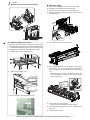
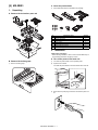
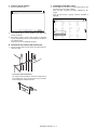
[4] MX-FNX9
B.
Removal
of the fixing tape and protection
Service
Manual
material
1.
1)
Unpacking
Remove the fixing tape and protection material.
A. Removal of the inner finisher
C. Check the packed items
1)
Check that all the items are included in the package.
1
2
4
3
5
6
7
* When removing the inner finisher, lift it as shown in the table
below.
8
No.
1
2
3
4
5
6
7
8
9
10
11
12
13
14
9
11
12
13
14
10
Packed part names
Finisher fixing plate
Front slide rail
Dummy punch unit
Front open/close cover
Punch cover
Left front cover
Finisher slide stopper
Fixing screw
Resin clip
Coin screw
Staple position label (For scanner)
Staple position label (For RSPF/DSPF)
Punch position label (For scanner)
Punch position label (For RSPF/DSPF)
Quantity
1
1
1
1
1
1
1
8
1
1
1
1
1
1
* The punch position labels (No.13 and No.14) should be kept at
hand since they will be necessary when installing the punch unit.
MX-M503N MX-FNX9 4 – 1
1
2.
: '10/Jun/18
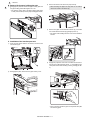
Installation
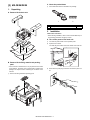
C. Installation of the inner finisher
<Note before installation>
1)
Open the front cover.
2)
Remove two screws, and remove the front cabinet upper.
3)
Disengage two pawls, and remove the paper exit tray cover.
4)
Remove four screws, and remove the paper exit tray.
* Before starting installation, check to insure that the data lamp on
the operation panel does not light up or blink.
A. Turn off the power of the main unit
1)
Turn OFF the power switch on the operation panel.
2)
Open the front cabinet.
Turn OFF the power switch in the front cabinet of the main unit.
OFF
3)
Disconnect the power plug of the main unit from the power outlet.
B. Removal of the paper holding plate unit
1
1)
Disengage the pawl, and remove the paper holding plate and
the paper holding plate holder together as a unit.
* Be careful to remove both of the paper holding plate (which
is easily removed alone) and the paper holding plate holder.
* When removing the paper exit tray, there is no need to
remove the screws in the section (A).
A
MX-M503N MX-FNX9 4 – 2
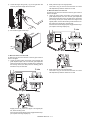
5)
Remove the paper exit full detection actuator.
6)
Engage the projection on the main unit frame with the hole in
the finisher fixing plate (package part No. 1).
7)
Fix the right cover plate with the fixing screw (package part No.
8).
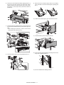
9)
Fix the dummy punch unit (package part No. 3) with the fixing
screw (package part No. 8).
10) Check to insure that the slide roller is in the rail groove, and
insert the inner finisher.
11) Fix the rear slide rail with the fixing screw (package part No. 8).
* Fix the side plate of the paper exit shifter with the fixing
guide.
8)
Install the front slide rail (A) (package part No. 2) with the three
fixing screws (package part No. 8), and install the left front
cover (B) (package part No. 6) with one fixing screw (package
part No. 8).
12) After pushing the intermediate rail of accuride, insert the finisher slide stopper (package part No. 7) between the rear slide
rail and the accuride.
Fix it with the coin screw (package part No. 10).
A
B
MX-M503N MX-FNX9 4 – 3
13) Install the front open/close cover (package part No. 4) to the
front rail stay rotating shaft, and fix it with the resin clip (package part No. 9).
D. Connector Installation
1)
Remove the protection material and fixing tape.
2
1
2
1
14) Fix the punch cover (package part No. 5) together with the
band (metal fixture) with the fixing screw (package part No. 8).
2)
Remove the screw, and remove the connector cover.
3)
Connect the finisher connector with the main unit connector,
and tighten with a screw.
1
2
15) Install the front cabinet upper with two screws.
MX-M503N MX-FNX9 4 – 4
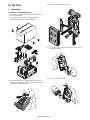
E. Staple position label attachment
F. Turn on the power of the main unit
1)
1)
Insert the power plug of the main unit into the power outlet.
2)
Open the front cabinet.
Attach the label to the position indicated in the figure.
[For scanner] (package part No. 11)
Second label
Corner R end fitting
Label attachment
reference
Corner of the "upper
cabinet rear"
Corner R end fitting
Turn ON the power switch in the front cabinet of the main unit.
ON
[For DSPF/RSPF] (package part No. 12)
3)
Turn ON the power switch on the operation panel.
DSPF
1mm
1mm
RSPF
1mm
1mm
MX-M503N MX-FNX9 4 – 5
MX-M503N
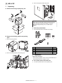
[5] MX-PNX1
2.
Installation
Service
Manual
1.
* When the punch unit is installed together with installation of
the MX-FNX9 (inner finisher), first install the inner finisher,
and then install the punch unit.
Unpacking
A. Removal of the punch unit
<Note before installation>
* Before starting installation, check to insure that the data lamp on
the operation panel does not light up or blink.
* Do not install the punch unit first because doing so would cause
interference between the inner finisher slide rail and the punch
unit drawer connector (possibly resulting in failure) when you
attempt to install the inner finisher.
A. Turn off the power of the main unit
1)
Turn OFF the power switch on the operation panel.
2)
Open the front cabinet.
Turn OFF the power switch in the front cabinet of the main unit.
B. Removal of the fixing tape
1)
Remove the fixing tape.
OFF
3)
Disconnect the power plug of the main unit from the power outlet.
C. Check the packed items
1)
Check that all the items are included in the package.
1
No.
1
2
Packed part names
Punch position label (For scanner)
Punch position label (For RSPF/DSPF)
2
Quantity
1
1
* Do not use the punch position label which is one of the packed
parts, but use one packed in the package of the finisher (MXFNX9).
MX-M503N MX-PNX1 5 – 1
B. Installation of the punch unit
1)
Open the front cabinet.
2)
Open the front cover and slide the inner finisher to the left.
5)
Remove two screws, and remove the front cabinet upper.
6)
Remove the screw, and remove the band and the punch cover.
7)
Remove the screw, and remove the dummy punch unit.
8)
Fix the punch unit with a screw.
2
1
3)
Remove the coin screw, and remove the finisher slide stopper.
4)
Slide the inner finisher further more.
* When installing the punch unit, be careful not to bump it
against the drawer connector.
* Fit the positioning pin and insert it.
3
2
1
MX-M503N MX-PNX1 5 – 2
9)
Make positioning with the dove (A) and fix the punch unit with
the screw which was fixing the dummy punch unit.
13) Insert the dust box.
A
A
14) Install the front cabinet upper part using the two screws
removed in step 5).
10) Cut the lid of the punch cover with nippers.
11) Remove the dust box.
15) Insert the finisher slide stopper between the slide rail and the
accuride, and fix it with the coin screw.
12) Fix the punch cover and the band together with one screw.
1
16) Slide the inner finisher to the original position, and close the
front cover.
2
1
2
MX-M503N MX-PNX1 5 – 3
C. Punch position label attachment
D. Turn on the power of the main unit
1)
1)
Insert the power plug of the main unit into the power outlet.
2)
Open the front cabinet.
Attach the label to the position indicated in the figure.
[For scanner] (Part No. 13 in the package of the MX-FNX9)
Lose the
clearance.
First label
Second label
Corner R end fitting
Label attachment
reference
Corner of the "upper
cabinet rear"
Corner R end fitting
Turn ON the power switch in the front cabinet of the main unit.
ON
[For DSPF/RSPF] (Part No. 14 in the package of the MXFNX9)
3)
Turn ON the power switch on the operation panel.
DSPF
1mm
1mm
RSPF
1mm
1mm
MX-M503N MX-PNX1 5 – 4
[6] MX-RBX3
MX-M503N
1.
C.
Check the
packed items
Service
Manual
1)
Check that all the items are included in the package.
Unpacking
A. Removal of the interface pass unit
1
5
4
No.
1
2
3
4
5
6
7
2.
2
6
3
7
Packed part names
Right cover plate
Interface left cabinet
Reverse tray
Fixing screw A
Resin clip
Reverse detection actuator
Front cabinet upper C
Quantity
1
1
1
6
1
1
1
Installation
<Note before installation>
* Before starting installation, check to insure that the data lamp on
the operation panel does not light up or blink.
A. Turn off the power of the main unit
B. Removal of the fixing tape
1)
Turn OFF the power switch on the operation panel.
1)
2)
Open the front cabinet.
Remove the fixing tape.
Turn OFF the power switch in the front cabinet of the main unit.
OFF
3)
Disconnect the power plug of the main unit from the power outlet.
MX-M503N MX-RBX3 6 – 1
1
: '10/Jun/18
B. Removal of the paper holding plate unit
1
1)
3)
Remove the screws, and remove the paper exit tray.
* When removing the paper exit tray, there is no need to
remove the screws in the section (A).
Disengage the pawl, and remove the paper holding plate and
the paper holding plate holder together as a unit.
* Be careful to remove both of the paper holding plate (which
is easily removed alone) and the paper holding plate holder.
A
4)
Remove the paper exit full detection actuator (A), and install
the reverse detection actuator (B) (package part No. 6).
* Be careful of the installing direction of the reverse detection
actuator.
C. Installation of the interface pass unit
1)
Open the front cabinet. Remove the screws, and remove the
front cabinet upper.
1
2
A
B
5)
2)
B
Engage the projection of the main unit frame with the hole in
the right cover plate (package part No. 1), and install the right
cover plate and fix it with the fixing screw A (package part No.
4).
Disengage the pawls, and remove the paper exit tray cover.
* Be sure to clamp and fix the paper exit tray shifter side plate
with the fixing guide.
MX-M503N MX-RBX3 6 – 2
1
6)
Insert the rib of the interface left cabinet (package part No. 2)
into the slit on the lower surface of the scanner left cabinet.
Install the interface left cabinet with the fixing screw A (package part No. 4) of the paper exit tray which was removed in
procedure 4).
9)
Remove the front connection cabinet from the front cabinet
upper, and attach it to the front cabinet upper C (package part
No. 7).
10) Install the front cabinet upper C unit, and fix with the screws.
7)
Insert the reverse tray (package part No. 3) along the groove in
the interface left cabinet and the top surface of the right cover
plate.
* When inserting the reverse tray, check to insure that the
switch guide of the reverse tray is up.
11) Insert the interface pass unit along the guide rail.
8)
Fix the reverse tray with the resin clip (package part No. 5).
12) Fix the interface pass disconnection preventing lever with the
fixing screw A (package part No. 4).
13) Go to the saddle finisher installing procedure.
MX-M503N MX-RBX3 6 – 3
[7] MX-FN10
MX-M503N
1.
3) Remove the
skid and packing cushions.
Service
Manual
Unpacking
A. Removal of the saddle finisher
* For removal of the saddle stitch finisher, manpower of two persons or more is required.
1)
Remove the fixing material, and remove the top case.
Remove the packing cushion and bundled items.
4)
One person tilt the saddle stitch finisher, another person
remove the lower tray.
1
2
5)
2)
Remove the other side similarly.
Holding the upper part of the saddle stitch finisher by two people, pull up the saddle stitch finisher, and make it stand upright.
1
(Be careful to sliding worker's foot.)
2
MX-M503N MX-FN10 7 – 1
B. Removal of the fixing tape and protection
material
2.
Installation
1)
* Make sure that none of the data lamps on the operation panels
are lit or flashing before starting the installation work.
<Note before installation>
Remove the fixing tape and protection material.
* Installing the MX-FN10 requires that the option desk (MX-DEX8/
DEX9) and junction unit (MX-RBX3) be installed in advance. Be
sure to complete the installation of the option desk (MX-DEX8/
DEX9) and junction unit (MX-RBX3) before installing the saddle
finisher.
* Make sure that the connection plate provided on the front side of
the option desk is securely installed.
Make sure that the connection plate (package part No. 2)
included in the package is securely installed.
A. Replacement of the Operation Manual storage
cover
1)
Remove the Operation Manual storage cover on the left side of
the machine.
1
C. Check the packed items
1)
2
Check that all the items are included in the package.
1
2
3
2)
4
5
10
No.
1
2
3
4
5
6
7
8
9
10
11
12
13
6
11
2
7
12
Packed part names
Paper exit tray
Connection plate
Saddle tray
Paper holding A
Paper holding B
Fixing screw A
Fixing screw B
Fixing screw C
Staple cartridge
Staple position label (For scanner)
Staple position label (For RSPF/DSPF)
Punch position label (For scanner)
Punch position label (For RSPF/DSPF)
8
Install the Operation Manual storage cover (which was
removed from the machine) to the saddle finisher.
9
13
Quantity
1
1
1
1
1
5
2
2
1
1
1
1
1
B. Installation of the paper exit tray
1)
Engage the pawls (two positions) of the paper exit tray (package part No. 1) on the finisher.
Fix the paper exit tray with fixing screws A (package part No.
6).
* The punch position labels (No.12 and No.13) should be kept at
hand since they will be necessary when installing the punch unit.
MX-M503N MX-FN10 7 – 2
2)
Fix the paper holding A with fixing screws A (package part No.
6).
(1)
1)
When the guide pin is not fit with the connection
hole in the finisher:
Loosen the fixing screw of the adjustment section on the rear
side. Adjust the height adjustment screw so that the guide pin
is fit with the connection hole in the finisher.
* By making space between the main body and ground, the
adjustment screw can be turned by the finger.
2
3)
1
Installation of tee saddle tray and paper holding B.
2)
Remove the two screws, and remove the front under cover
and foot cover.
C. Staple cartridge installation
1)
Insert the staple cartridge (package part No. 9).
1
2
3)
Loosen the fixing screw of the adjustment section on the front
side. If the guide pin is inserted smoothly, tighten the fixing
screws of the adjustment section on the front/rear sides.
* By making space between the main body and ground, the
adjustment screw can be turned by the finger.
2
D. Height adjustment of the finisher
1)
Put the finisher closer to the main unit, and check to insure that
the guide pin is smoothly inserted into the connection hole.
A
A
1
Connection hole
Guide pin
* If the guide pin is not inserted smoothly, perform the following adjustment.
MX-M503N MX-FN10 7 – 3
(2)
When the guide pin is fit with the connection hole
in the finisher:
1)
Insert the finisher into the main unit. Check to insure that the
upper and lower clearances between the main unit and the finisher are even.
E. Connection of the main unit and saddle
finisher
1)
Fix the connection plate (package part No. 2) to the paper feed
desk with fixing screws B (package part No. 7).
2)
Install the rail bracket to the frame with fixing screws C (package part No. 8).
Clearance
Clearance
2)
If the upper and lower clearances between the main unit and
the finisher are not even, remove the screw (one for each) of
the foot covers on the front/rear sides, and remove the foot
cover.
3)
Loosen four fixing screws of the adjustment section, and turn
the height adjustment screws on the front/rear sides to adjust
so that the clearances are even.
* By making space between the main body and ground, the
adjustment screw can be turned by the finger.
F. Connector connection
1)
2
1
4)
Connect the finisher connector with the connector of the interface pass unit, and tighten the screw.
2
1
When the clearances are even, tighten the fixing screw of the
adjustment section, and install the foot cover.
MX-M503N MX-FN10 7 – 4
2)
Connect the finisher connector with the connector of the main
unit, and tighten the screw.
H. Turn on the power of the main unit
1)
Insert the power plug of the main unit into the power outlet.
2)
Open the front cabinet.
Turn ON the power switch in the front cabinet of the main unit.
G. Staple position label attachment
1)
Attach the label to the position indicated in the figure.
[For scanner] (package part No. 10)
ON
Corner R end fitting
Label attachment
reference
Corner R end fitting
* Corner of the
"upper cabinet rear"
3)
Turn ON the power switch on the operation panel.
[For DSPF/RSPF] (package part No. 11)
DSPF
1mm
1mm
RSPF
1mm
1mm
MX-M503N MX-FN10 7 – 5
[8] MX-PNX5A/B/C/D
MX-M503N
3) Disconnect
the power plug of the main unit from the power outService
Manual
let.
1. Unpacking
A. Removal of the punch unit
4)
Disconnect the connector between the main unit and the saddle finisher.
B. Check the packed items
1)
Check that all the items are included in the package.
1
2
000-0000
3
No.
1
2
3
Packed part names
Harness A (Purple)
Harness B (Gray)
Punch jam processing label
Quantity
1
1
1
* Use the punch position labels bundled with the MX-FN10.
2. Installation
<Note before installation>
* Before starting installation, check to insure that the data lamp on
the operation panel does not light up or blink.
A. Turn off the power of the main unit
1)
Turn OFF the power switch on the operation panel.
2)
Open the front cabinet.
B. Installation of the punch unit
1)
Release the lock and separate the saddle finisher from the
main unit.
Turn OFF the power switch in the front cabinet of the main unit.
OFF
MX-M503N MX-PNX5A/B/C/D 8 – 1
2)
3)
Remove the screw, and remove the rear cover.
5)
Remove the screw, and remove the dummy punch guide.
6)
Install the punch unit to the saddle finisher.
Fix the punch unit with the screw which was removed from the
dummy punch guide.
Remove the screw, and remove the front lower cover.
* Before installing, remove the dust box.
* Check to confirm that the punch guide pin is securely
inserted into the guide pin insertion hole of the finisher.
* Check to confirm that the pawl (A) is engaged with the plate
frame.
1
2
4)
Open the front cover. Remove the screw, and remove the front
inner cover.
A
7)
Connect the harness on the punch unit side with the PWB on
the finisher side.
MX-M503N MX-PNX5A/B/C/D 8 – 2
8)
Fix the front inner cover with screws, and close the front
cover.
11) Install the saddle finisher to the main unit.
C. Punch jam processing label attachment
1)
9)
Open the front cover, apply the punch jam processing label
(package part No. 3) in position as shown in the figure.
Fix the front lower cover with a screw.
000-0000
Label attachment reference
2
D. Punch position label attachment
1
1)
Attach the label to the position indicated in the figure.
[For scanner]
10) Fix the rear cover with a screw.
Lose the
clearance.
First label
Second label
Corner R end fitting
Label attachment
reference
Corner of the "upper
cabinet rear"
MX-M503N MX-PNX5A/B/C/D 8 – 3
Corner R end fitting
[For DSPF/RSPF]
2)
Insert the power plug of the main unit into the power outlet.
3)
Open the front cabinet.
DSPF
1mm
1mm
Turn ON the power switch in the front cabinet of the main unit.
ON
RSPF
1mm
1mm
E. Turn on the power of the main unit
1)
4)
Turn ON the power switch on the operation panel.
Connect the connector.
MX-M503N MX-PNX5A/B/C/D 8 – 4
[9] MX-FN11
MX-M503N
4) Remove the
skid and packing cushions.
Service
Manual
1. Unpacking
A. Removal of the finisher
* For removal of the finisher, manpower of two persons or more is
required.
1)
Remove the fixing material, and remove the top case.
2)
Remove the bundled items from packing cushion.
5)
One person tilt the finisher, another person remove the lower
tray.
3)
Holding the upper part of the saddle stitch finisher by two people, pull up the saddle stitch finisher, and make it stand upright.
(Be careful to sliding worker's foot.)
6)
Remove the other side similarly.
MX-M503N MX-FN11 9 – 1
B. Removal of the protection material
C. Check the packed items
1)
1)
Remove the fixing tapes and protection material.
Check that all the items are included in the package.
1
2
4
3
5
7
6
8
9
X3
X3
11
10
13
2)
3)
12
14
15
16
Open the front upper door, and remove the fixing tapes and
protection material.
Remove the screws and remove the fixing material for the
paper exit tray. (four positions)
No.
1
2
3
4
5
6
7
8
9
10
11
12
13
14
15
16
Names of bundles
Binding head round tapping M4x8
IT tapping M4x20
Binding head M4x12
Step screw B
Rail
Rail reception sheet metal
Connection fixture F (for x3)
Connection fixture R (for x3)
Staple position label (For scanner)
Staple position label (For RSPF/DSPF)
Punch position label (For scanner)
Punch position label (For RSPF/DSPF)
Guide mylar
Cushion (S)
Cushion (M)
Cushion (L)
Quantity
2
2
4
2
1
1
1
1
1
1
1
1
2
1
1
1
* The punch position labels (No.11 and No.12) should be kept at
hand since they will be necessary when installing the punch unit.
MX-M503N MX-FN11 9 – 2
2. Installation
2)
<Note before installation>
Install the rail reception sheet metal (Package part No. 6) to
the main unit with the fixing screws (Package part No. 2).
* Installing the MX-FN11 requires that the option desk (MX-DEX8/
DEX9) and junction unit (MX-RBX3) be installed in advance. Be
sure to complete the installation of the option desk (MX-DEX8/
DEX9) and junction unit (MX-RBX3) before installing the finisher.
* When the MX-FN11 and MX-PNX6A/B/C/D is installed at the
same time, first install the MX-PNX6A/B/C/D, and then install the
MX-FN11.
A. Replacement of the Operation Manual storage
cover
1)
Remove the Operation Manual storage cover on the left side of
the machine.
1
2
C. Removal of the paper pass latch reception
parts and the positioning pin
1)
Remove the screw, and release the paper pass disconnection
preventing lever.
2)
Remove the paper pass unit.
3)
Remove the resin E-ring that secures the reverse tray.
2
2)
Install the Operation Manual storage cover (which was
removed from the machine) to the finisher.
B. Installation of the rail
1)
Install the rail (Package part No. 5) to the finisher with the fixing screws (Package part No. 1).
MX-M503N MX-FN11 9 – 3
4)
D. Attaching the mylar
Remove the reverse tray.
1)
Attach the mylar (package part No.13) to the position indicated
in the figure.
Reference
Reference
Corner
reference
Corner
reference
5)
Remove the screws, and remove the interface left cabinet.
E. Installation of the connection fixture F/R
6)
1)
Install the connection fixture R (Package part No. 8) to the
main unit with the fixing screws (Package part No. 3).
2)
Install the connection fixture F (Package part No. 7) to the
main unit with the fixing screws (Package part No. 3).
Remove the screws, and remove the paper pass latch reception parts and the positioning pin.
MX-M503N MX-FN11 9 – 4
F. Attaching the cushion
1)
3)
Attach the cushion (S) (package part No.14), the cushion (M)
(package part No.15) and the cushion (L) (package part No.16)
to the position indicated in the figure.
Check that the center of the screw hole of the finisher is in the
range of specification of an oval hole of the connection fixture
that exist on main body rear side.
Reference
Cushion (M)
Reference
Reference
Reference
Cushion (L)
Reference
Reference
* When not the range of specification, progress to the procedure of "H. Adjustment".
If the adjustment is not required, remove the screws from
the screw hole directly and push the caster into it until the
installation fixing.
Cushion (S)
G. Check of the connected position of main unit
and finisher
1)
Insert the rail of the finisher into the slit on the rail reception
sheet metal of the main unit, install the finisher.
2)
Remove the screw, and remove the connector cover on rear
side of the finisher.
H. Adjustment
1)
Remove the finisher from the main unit.
MX-M503N MX-FN11 9 – 5
2)
Remove the screw, slide to the left the front lower cover, and
remove it.
3)
Open the front upper door, and remove the screw.
4)
5)
Remove the fixing tapes.
6)
Remove the screws, and remove the auxiliary wheels.
7)
Remove the screws, and remove the rear lower cover.
8)
Remove the fixing tapes.
Remove the screws, and open the front cover.
MX-M503N MX-FN11 9 – 6
9)
Loosen both of the caster fixing screws of the front side and
rear side.
11) Turn the bolt for which the adjustment is necessary, and adjust
to become it within the range of specification.
12) Check to insure that the upper and lower clearances between
the main unit and the finisher are even.
10) Remove the screw, and remove the spanner installed inside
the front lower door.
MX-M503N MX-FN11 9 – 7
13) Tighten the caster fixing screws so that the indicator scale is
fit.
16) Install the spanner for adjustment to inside the front lower door.
17) Close the front cover, and secure it with the fixing screws.
14) Install the rear lower cover with the fixing screws.
18) Attach the fixing screw, and close the front upper door.
15) Install the auxiliary wheels with the fixing screws.
MX-M503N MX-FN11 9 – 8
19) Attach the front lower cover with the fixing screw.
4)
Close the front cover.
5)
Remove the screw, and remove the connector cover on rear
side of the finisher.
6)
Install the Step screw B (Package part No. 4).
7)
Attach the connector cover on rear side of the finisher.
I. Connection of the finisher
1)
Engage the finisher to the main unit.
2)
Open the front cover of finisher.
3)
Fix the finisher to the main unit with the step screw B (Package
part No. 4).
MX-M503N MX-FN11 9 – 9
J. Connection of connector to the main unit
1)
[For DSPF/RSPF] (Package part No. 10)
Connect two connectors of the finisher to the main unit, and
tighten the screws.
DSPF
1mm
1mm
RSPF
1mm
1mm
K. Staple position label attachment
1)
Attach the label to the position indicated in the figure.
[For scanner] (Package part No. 9)
L. Turn ON the main power switch of the main
unit
1)
Connect the power plug of the main unit into the power outlet.
2)
Open the front cabinet of the main unit. Turn ON the power
switch in the front cabinet.
Corner R end fitting
Label attachment
reference
Corner R end fitting
* Corner of the
"upper cabinet rear"
ON
3)
Turn ON the power switch on the operation panel.
MX-M503N MX-FN11 9 – 10
MX-M503N
[10]
MX-PNX6A/B/C/D
2) Open theManual
front cover, and open the top cover.
Service
1. Unpacking
2
A. Pulling out of the punch unit
1)
Pull out the punch unit.
1
3)
Remove the screws, and remove the fixing material. (2 positions)
4)
Close the top cover, and close the front cover.
B. Removal of the protection material
1)
Remove the fixing tape and protection material.
2
1
MX-M503N MX-PNX6A/B/C/D 10 – 1
C. Check the packed items
1)
3)
Check that all the items are included in the package.
1
2
Hang the punch unit on the step screws installed to the finisher.
3
2
5
4
1
6
7
8
P
P
No.
1
2
3
4
5
6
7
8
Names of bundles
P tight M4x12
Step screw A
Cap screw M3x6
Binding head M4x12
Front cover
Front cover mounting fixture
Connection fixture F (for punch)
Connection fixture R (for punch)
4)
Tighten the step screws bundled to the punch unit, fix the
punch unit.
5)
Attach the front cover mounting fixture (Package part No. 6)
with the fixing screws (Package part No. 3).
Quantity
1
2
3
4
1
1
1
1
2. Installation
<Note before installation>
* Before installing the MX-PNX6A/B/C/D, unpack the MX-FN11.
A. Installation of punch unit
1)
Attach the step screw A (Package part No. 2) to the finisher.
Remove the screw of the finisher, and reuse it. Install it using
the reuse screw, and three fixing screws (Package part No. 3)
bundled to punch unit.
2
3
1
2)
Remove the fixing screw, and remove the connector cover on
rear side of the finisher.
MX-M503N MX-PNX6A/B/C/D 10 – 2
6)
7)
C. Install of the Connection fixture F/R
Open the front door of punch unit.
Engage the pawls of the rear side of front cover (Package part
No. 5), attach the front cover with the fixing screw (Package
part No. 1).
B. Connection of connector of the finisher and
punch unit
1)
Remove the fixing screws, and remove the rear cover.
1)
Install the Connection fixture F (Package part No. 7) to the
main unit with the fixing screws (Package part No. 4).
2)
Install the Connection fixture R (Package part No. 8) to the
main unit with the fixing screws (Package part No. 4).
D. Check of the connected position of main unit
and finisher
1)
Engage the finisher that has installed punch unit to the main
unit, and temporarily fix.
* Insert the rail of the finisher unit into the rail reception fixture
of main unit, fix temporarily.
2)
Connect two connectors of the finisher to the PWB of punch
unit, and fix the harness to the clamp.
MX-M503N MX-PNX6A/B/C/D 10 – 3
2)
E. Adjustment
Open the front door of punch unit.
* Refer to the adjustment procedures in the MX-FN11 Service
Manual.
F. Install to main unit
3)
1)
Engage the finisher that has installed punch unit to the main
unit.
2)
Open the front door of punch unit.
3)
Secure the main unit and the punch unit with the fixing screw
(Package part No. 4 of the MX-FN11).
Check that the center of the screw hole of the punch unit is in
the range of specification of an oval hole of the mounting fixture in front side of main unit.
* When not the range of specification, progress to the procedure of "E. Adjustment".
If the adjustment is not required, remove the screw from the
screw hole directly and push the caster into it until the installation fixing.
MX-M503N MX-PNX6A/B/C/D 10 – 4
4)
Close the front door of punch unit.
5)
Install the fixing screw (Package part No. 4 of MX-FN11) on
rear side.
8)
G. Connection of connector to the main unit
1)
6)
Install the connector cover of the finisher and fix it with the fixing screw.
Connect two connectors of the finisher to the main unit, and
tighten the screws.
Install the rear cover of punch unit with the fixing screws.
H. Punch position label attachment
1)
Attach the punch position label to the position indicated in the
figure.
[For scanner] (Package part No. 11 of the MX-FN11)
7)
By using nippers, split the removed connector cover of the finisher along the perforated line.
Lose the
clearance.
First label
Second label
Corner R end fitting
Label attachment
reference
Corner of the "upper
cabinet rear"
MX-M503N MX-PNX6A/B/C/D 10 – 5
Corner R end fitting
[For DSPF/RSPF] (Package part No. 12 of the MX-FN11)
DSPF
1mm
1mm
RSPF
1mm
1mm
I. Turn ON the main power switch of the main
unit
1)
Connect the power plug of the main unit into the power outlet.
2)
Open the front cabinet of the main unit. Turn ON the power
switch in the front cabinet.
ON
3)
Turn ON the power switch on the operation panel.
MX-M503N MX-PNX6A/B/C/D 10 – 6
MX-M503N
[11]
MX-TRX2
3) Remove the
power plug of the main unit from the outlet.
Service
Manual
1. Unpacking
A. Removal of the exit tray unit
B. Installation of the exit roller unit
1)
Open the right door.
2
1
B. Check the packed items
1)
Check that all the items are included in the package.
1
No.
1
2
2)
Remove the screw, and remove the connector cover.
3)
Remove the screw. Disengage the engagement in the front
side then in the rear side, and remove the paper exit cover.
2
Packed part names
Exit roller unit
Full detection actuator
Quantity
1
1
2. Installation
<Note before installation>
* Before starting installation, check to insure that the data lamp on
the operation panel does not light up or blink.
A. Turn off the power of the main unit
1)
Turn OFF the power switch on the operation panel.
2)
Open the front cabinet.
4
Turn OFF the power switch in the front cabinet of the main unit.
1
2
OFF
3
MX-M503N MX-TRX2 11 – 1
4)
Connect the connector, and install the exit roller unit (package
part No. 1). Use the screw which was removed in step 3) and
fix the unit.
C. Turn on the power of the main unit.
1)
Insert the power plug of the main unit into the power outlet.
2)
Open the front cabinet.
Turn ON the power switch in the front cabinet of the main unit.
5)
Install the connector cover, and fix it with the screw.
ON
3)
Turn ON the power switch on the operation panel.
D. Tray setting
6)
Install the exit tray unit (A) and the full detection actuator (B)
(package part No. 2).
Use SIM26-1 to set the tray YES/NO.
* Be careful of the installing direction of the full detection actuator.
B
B
A
MX-M503N MX-TRX2 11 – 2
MX-M503N
[12] MX-FXX2
B.
Attach Manual
the fax box unit to the rear part of the
Service
main unit.
1.
1)
Remove the two screws from the rear cabinet of the main unit.
2)
Attach the supplied step screw to one of the two positions from
which the screws are removed.
Unpacking
A. Parts included
M3 Screw:
Installation
directions:
Line cable:
Australia
2.
3)
Insert the step screw into the mounting hole of the fax box unit.
4)
Use a screw that has been removed in step 1) to secure the
fax box unit.
Installation
<Note before installation>
• Start installation after checking that the LINE indicator and the
DATA indicator below it on the operation panel are neither lit nor
blinking.
A. Turn off the power switches of the main unit.
1)
Turn the power switch located on the operation panel to the
“OFF” position.
2)
After checking that the operation panel has gone out, open the
front cabinet and turn the main power switch to the “OFF” opsition.
C. Pull out the control PWB.
1)
Push the location indicated in the illustration to unlock, and
remove the ozone filter cover from the right cabinet rear.
2)
Remove the screw from the right cabinet rear and remove the
right cabinet rear.
OFF
3)
Remove the power plug of the main unit from the outlet.
2
Screw
MX-M503N MX-FXX2 12 – 1
3)
Remove the two screws from the control PWB unit.
4)
Pull out the control PWB unit.
F. Attach the control PWB and the right cabinet
rear.
1)
Push the control PWB unit into the main unit and secure it with
the two screws.
2)
Cut out the cut-out portion of the right cabinet rear.
D. Attach the FAX memory.
2
PROG1
PROG2
FAX IMG EXT
PCL/BARCODE
PS KANJI
3)
Fit the interface cable into the opening that has been cut.
4)
Attach the right cabinet rear cover to the main unit.
At this time, check that the four hooks are properly fitted to the
main unit.
5)
Secure the right cabinet rear with the screw.
Hook 1 Hook 2
E. Attach the interface cable.
1)
Connect the interface cable to the control PWB unit.
2)
Push the interface cable into the recessed portion of the sheet
metal on the control PWB unit.
3)
Fix a snap band with the bundled M3 screw.
Hook 3
[Note] Check that the connector is not obliquely inserted.
4
Hook 4
3
1
3
5
2
6)
Attach the ozone filter cover to the main unit.
MX-M503N MX-FXX2 12 – 2
I. Clear the FAX related software switches.
G. Turn on the main power switch of the main
unit.
1)
1)
Enter the SIM 66-2 mode.
Insert the power plug of the main unit to the outlet.
ǂǂǂ6,08/$7,21ǂǂ12
7(67
&/26(
)$;62)76:&/($5-$3$1
35(6(17˖
ǂǂ1(:˖
6(7
$5(<28685("
'(67&2'(
2)
Turn on the main power switch.
<(6
(;(&87(
12
2)
Enter the country code (8 digits) with the 10-key.
3)
Press [SET], [EXECUTE], and [YES] keys.
NOTE: When [DEST CODE] key is pressed, the country code list
is displayed.
ON
ǂǂǂ6,08/$7,21ǂǂ12
7(67
&/26(
)$;62)76:&/($5
-$3$1˖86$˖
$8675$/,$˖8.˖
)5$1&(˖*(50$1<˖
6:('(1˖1(:=($/$1'˖
&+,1$˖6,1*$325(˖
7:˖0,''/($1'1($5($6˖
6/29$.,$˖27+(5˖
),1/$1'˖125:$<˖
3)
Turn on the power switch located on the operation panel.
'(10$5.ǂ˖1(7+(5/$1'6˖
,7$/<˖6:,7=(5$1'˖
H. Set the destination and the logo type.
1)
$8675,$˖,1'21(6,$˖
7+$,/$1'˖0$/$<6,$˖
Enter the SIM 26-6 mode.
%$&.
ǂǂǂ6,08/$7,21ǂǂ12
7(67
&/26(
'(67,1$7,216(783
86$
&$1$'$
,1&+
-$3$1
$%B%
(8523(
8.
$86
$%B$
&+,1$
(;(&87(
2)
Press the key corresponding to the destination.
U.S.A.
CANADA
INCH
JAPAN
AB_B
EUROPE
U.K.
AUS.
AB_A
CHINA
3)
United States of America
Canada
Inch series, other destinations
Japan
AB series (B5 detection), other destinations
Europe
United Kingdom
Australia
AB series (A5 detection), other destinations
China
JAPAN
U.S.A.
AUSTRALIA
U.K.
FRANCE
GERMANY
SWEDEN
NEWZEALAND
CHINA
SINGAPORE
TW
MIDDLEANDNE
AREAST
SLOVAKIA
OTHER3
FINLAND
NORWAY
DENMARK
NETHERLANDS
ITALY
Press [EXECUTE] key.
MX-M503N MX-FXX2 12 – 3
:
:
:
:
:
:
:
:
:
:
:
:
Country code list
00000000
SWITZERLAND
10110101
AUSTRIA
00001001
INDONESIA
10110100
THAILAND
00111101
MALAYSIA
00000100
INDIA
10100101
PHILIPPINES
01111110
HONGKONG
00100110
RUSSIA
10011100
SOUTHAFRICA
11111110
SPAIN
11111101
PORTUGUESE
:
:
:
:
:
:
:
:
:
:
:
:
10100110
00001010
01010100
10101001
01101100
01010011
10001001
01010000
10111000
10011111
10100000
10001011
:
:
:
:
:
:
:
11111100
11111011
00111100
10000010
00110001
01111011
01011001
:
:
:
:
:
:
:
01101001
00001111
00101110
01010001
01000110
10001010
00010110
LUXEMBURG
BELGIUM
CZECH
HUNGARY
GREECE
POLAND
BRAZIL
J. Clear the image memory.
L. Installation completion check
1)
1)
Enter the SIM 66-10 mode.
ǂǂǂ6,08/$7,21ǂǂ12
7(67
&/26(
,0$*(0(025<&/($5
Execute SIM 22-10 to check to confirm that the FAX box and
the FAX memory are properly installed.
When the FAX1 is properly connected, "MX-FXX2" is displayed.
When the FAX memory is properly connected, "AR-MM9" is
displayed.
ǂǂǂ6,08/$7,21ǂǂ12
7(67
&/26(
0$&+,1(6<67(0
0$&+,1(0;01
$5(<28685("
<(6
12
(;(&87(
360;3.;
63)67$1'$5'
;360;38;
67$03$568
6(&85,7<0;)58
'(6.0;'(;
$,00;$0;
/&&0;/&;
6'5$06<6ˆˆˆˆˆ0%
381&+(50;31;$
6'5$0,&8ˆˆˆˆˆ0%
),1,6+(50;)1;
+''ˆˆˆˆˆ0%
)$;0;);;
1,&67$1'$5'
2)
Press [EXECUTE] key and then [YES] key. (The FAX image
memory is cleared.)
)$;121(
%$5&2'($53)
)$;ǂ0(025<$500
)217121(
+$1'ǂ6(7121(
,17(51(7)$;0;):;
3)
After several minutes, memory clear operation is completed
and the [YES] button goes out. Press the [CA] key to exit from
the simulation mode.
1(7:25.ǂ6&$11(50;16;
$&00;$0;
35,17(50;3%
($00;$0;
Then the main unit is automatically rebooted.
K. Connect the line cable to the fax box unit.
1)
Connect the line cable of the line side to the modular jack indicated with “LINE.”
• For using an external telephone:
For using an external telephone, wind the line cable around
the supplied ferrite core by two turns and connect the cable
to the modular jack indicated with “TEL.”
MX-M503N MX-FXX2 12 – 4
[13] AR-SU1
MX-M503N
1.
3) Disconnect
the power plug from the power outlet.
Service
Manual
Unpacking
A. Remove the stamp unit
B. Install the stamp unit
1)
For removing and fixing screws, use a stubby screwdriver.
B. Check the parts in the package
1)
Check to confirm that all the parts are included in the package.
1
2
3
No.
1
2
3
4
4
Part name
Stamp unit
Stamp cartridge replacement procedure*
Stamp cartridge
Installing screw
Quantity
1
1
3
1
* When replacing the stamp cartridge, Refer to “Stamp cartridge
replacement” in the “User’s Guide” (PDF document). The user
must be notified of that. (Do not refer to “Stamp cartridge replacement procedure” (package part No. 2).)
2.
Open the DSPF/RSPF unit, and remove the OC mat.
Installation
* If stubby screwdriver is not available, loosen the screw of
the angle adjustment plate on the rear side of the machine,
and lower the angle adjustment plate and put the DSPF/
RSPF unit straight.
<Note before installation>
* Before execution of installation, check to confirm that the data
lamp on the installation panel does not light or flash.
A. Turn off the power of the main unit
1)
Turn OFF the power switch on the operation panel.
2)
Open the front cabinet, and turn OFF the power switch.
OFF
MX-M503N AR-SU1 13 – 1
2)
Remove the sensor cover. Remove the stamp case, and
remove the earth cord.
3)
Attach the stamp unit (package part No. 1) to the stamp case
which was removed from the DSPF/RSPF unit with the installing screw (package part No. 4). (Fix it together with the earth
wire.)
4)
Install the stamp case unit, and connect the connector.
6)
Install the stamp cartridge (package part No. 3).
7)
Install the OC mat, and close the DSPF/RSPF unit.
* If the angle adjustment plate was lowered for installation, lift
the angle adjustment plate, and fix it with the screw, and
close the DSPF/RSPF unit.
5)
Install the sensor cover.
MX-M503N AR-SU1 13 – 2
C. Turn on the power of the main unit
1)
Insert the power plug into the power outlet.
2)
Open the front cabinet of the machine, and turn ON the power
switch.
ON
3)
Turn ON the power switch on the operation panel.
4)
Use SIM22-10 to check to confirm that the finish stamp (ARSU1) is recognized.
MX-M503N AR-SU1 13 – 3
[14] MX-PB10
MX-M503N
Service Manual
1. Unpacking
A. Parts included
1
No.
1
2
2
Packed part names
CD-ROM (Driver)
Product key sheet (With Application Number)
Quantity
1
1
2. Installation
A. Preparation for enabling the MX-PB10
1)
To enable the MX-PB10, enter the product key by the key
operation of the copier machine.
a)
Press the system setting key on the operation panel.
b)
Select [Product key input] key display page, and touch the
key.
c)
Touch the input column.
d)
Enter the product key with numeric key (10-key), and
touch [Registration] key.
2)
After completion of entry of the product key, turn OFF the
power switch on the operation panel. Turn OFF the main
power switch, then turn ON the power switch and the main
power switch again.
3)
Use the attached CD-ROM to install the driver.
For installing procedures, refer to the software setup guide.
Installation of the driver must be performed by the user or the
serviceman with assistance or the user.
Please keep below important information.
This information will use for other products.
APPLICATION
NUMBER
MACHINE
SERIAL
NUMBER
PRODUCT
KEY
MX-M503N MX-PB10 14 – 1
2.
Installation
Service
Manual
[15] MX-PB11
MX-M503N
A. Preliminary arrangements
1. Unpacking
NOTE: When this option is installed to a machine which has been
used by a user, be sure to backup the user data as shown
below.
When the MX-PB11 is installed, the user settings and the
registered data are initialized. (The simulation settings and
the adjustment data are not initialized.)
Before installing the MX-PB11, save the user data. After
completion of installation, the saved data. Must be
restored.
When this option is installed to a new machine, the procedure below is not required.
Once the product key is inputted after installation of the
MX-PB11, the model cannot be changed back to the U
model without HDD. Before entering the product key, however, the model can be changed back to the U model without HDD. In that case, however, the user settings and the
registered data are initialized.
1)
Use the device cloning function to backup the user setting data
stored in the SRAM and the EEPROM to a PC or USB memory.
Use the device cloning function on either the system setting or
the Web Page menu to backup the data.
2)
A. Parts included
Use the storage backup function to backup the user data
stored in the HDD to a PC or USB memory.
Use the storage backup function on either the system setting
or the Web Page menu to backup the data.
B. Turn off the power of the main unit
1
2
5
No.
1
2
3
4
5
6
3
6
Packed part names
HDD with frame (Included Water mark data)
HDD fixing screw
HDD rubber isolator
Flash ROM (Program 1/Program 2)
CD-ROM (Driver)
Product key sheet with Application number
4
1)
Turn the power switch located on the operation panel to the
"OFF" position.
2)
Open the front cabinet. Turn OFF the power switch in the front
cabinet of the main unit.
7
OFF
Quantity
1
4
4
2
1
1
3)
Disconnect the power plug of the main unit from the power outlet.
MX-M503N MX-PB11 15 – 1
C. Pull out the control PWB
2)
When installing the HDD to the MFP PWB frame, attach the
anti-vibration rubber to the HDD frame side and fix it with a
screw.
• If cables are connected to the control PWB unit, remove all
cables.
1)
Push the location indicated in the illustration to unlock, and
remove the cover from the right cabinet rear.
2)
Remove the screw from the right cabinet rear.
3)
Remove the right cabinet rear.
4)
Remove the two screws from the control PWB unit.
• If the fax box unit is installed, carry out steps 5), 6), and 7)
additionally.
5)
Install the HDD to the MFP PWB frame.
3)
Connect the HDD cable to the HDD.
4)
Replace the Flash ROM (Program 1/Program 2) installed to
the MFP PWB with the Flash ROM attached to the MX-PB11.
Pull out the control PWB unit and remove the snap band.
6)
Remove the interface cable from the frame.
7)
Remove the connector.
8)
Pull out and remove the control PWB unit.
7
4
6
3
8
5
5
4
2
D. HDD installation
1)
Put the cushion material used for packing the MX-PB11
beneath the MFP PWB frame.
NOTE: Be sure to perform this procedure in order to protect the
memory and the Flash ROM on the MFP PWB.
If this procedure is neglected, a stress may be applied to
the memory and the Flash ROM on the MFP PWB, causing
a trouble.
E. Reattach the control PWB and the right cabinet
rear
• If the fax box unit is installed, carry out steps 1), 2), and 3) additionally.
1)
Connect the interface cable to the control PWB unit.
2)
Push the interface cable into the recessed portion of the sheet
metal on the control PWB unit.
3)
Attach the snap band to the sheet metal of the control PWB
unit.
1
2
MX-M503N MX-PB11 15 – 2
3
4)
Push the control PWB unit into the main unit.
G. Preparation for enabling the MX-PB11
5)
Secure the unit with the two screws.
1)
To enable the MX-PB11, enter the product key by the key operation of the copier machine.
a)
Turn on the power. (The product key input menu is displayed.)
b)
Enter the product key with numeric key (10-key), and
touch [Registration] key.
2)
After completion of entry of the product key, turn OFF the
power switch on the operation panel. Turn OFF the main
power switch, then turn ON the power switch and the main
power switch again.
3)
Use the attached CD-ROM to install the driver.
For installing procedures, refer to the software setup guide.
6)
Fit the interface cable into the right cabinet rear cover.
7)
Attach the right cabinet rear cover to the main unit.
At this time, check that the four hooks are properly fitted to the
main unit.
8)
Installation of the driver must be performed by the user or the
serviceman with assistance or the user.
NOTE: If any trouble occurs during installing procedures, cancel
the trouble.
Please keep below important information.
This information will use for other products.
Secure the right cabinet rear with the screw.
Hook 1 Hook 2
Hook 3
7
APPLICATION
NUMBER
Hook 4
6
MACHINE
SERIAL
NUMBER
8
9)
PRODUCT
KEY
Attach the cover to the main unit.
H. User data restoring procedures
The data saved in the PC in the preliminary arrangement are
restored to the SRAM, the EEPROM, and the HDD.
• Reconnect the cables that have been removed in step B to the
original positions of the control PWB unit.
When this option is installed to a machine which has been used by
a user, be sure to backup the user data as shown below.
F. Turn ON the power of the main unit
When this option is installed to a new machine, the procedure
below is not required.
1)
1)
Insert the power plug of the main unit into the power outlet.
Use the device cloning function to restore the user setting data
which were backed up to the PC or USB memory to the SRAM
and the EEPROM.
Use the device cloning function on either the system setting or
the Web Page menu to restore the data.
2)
Use the storage backup function to restore the user setting
data which were backed up to the PC or USB memory to the
HDD.
Use the device cloning function on either the system setting or
the Web Page menu to restore the data.
I. Deletion of backup data
Delete the user data backed up to the PC or the USB memory.
When a PC or USB memory which belongs to the serviceman is
used for user data backup, be sure to delete the data after completion of work.
MX-M503N MX-PB11 15 – 3
MX-M503N
[16]
MX-FWX1
* This option requires installation of a HDD, and cannot be
used with the models having no HDD.
When this option is used with the U model, the MX-PB11
option must be installed.
1. Unpacking
B.
Operation
check of the Internet Fax send
Service
Manual
function
1)
After completion of entry of the product key, check to confirm
that the Internet Fax send is performed normally from the
machine.
2)
After completion of update of the PC-FAX driver, press the
print button on the test page of the PC-FAX driver to check to
confirm that the Internet Fax send is performed normally.
A. Check the packed items
1
No.
1
2
2
Packed part names
CD-ROM
Product key sheet
Quantity
1
1
2. Installation
<Note before installation>
• In order to enable the Internet Fax send function, the product key
must be acquired.
• In order to specify the address of the Internet Fax with the PCFAX driver, the PC-FAX driver must be updated by the Internet
Fax expansion kit.
A. Preparation for enabling the Internet Fax send
function
1)
2)
In order to enable the Internet Fax send function, enter the
product key by the key operation on the operation panel.
a)
Press the system setting key on the operation panel.
b)
Select page 2/2 of the system setting, and touch [Product
key input] key.
c)
Touch the input column.
d)
Enter the product key with numeric key (10-key), and
touch [Registration] key.
After completion of entry of the product key, turn OFF the
power switch on the operation panel. Turn OFF the main
power switch, then turn ON the power switch and the main
power switch again.
* After completion of 1) and 2), the Internet Fax send function
from the main unit becomes enable. To enable the Internet
Fax send with the PC-FAX driver, the following steps 3) and
4) are required.
3)
Use the CD-ROM packed together with the machine to install
the PC-FAX driver.
4)
Update the PC-FAX driver with the CD-ROM packed together
with the machine.
For installing procedures, refer to the software setup guide.
* Install and setting of the driver to the PC server must be performed by the user or by the request from the user.
MX-M503N MX-FWX1 16 – 1
: '10/Jun/18
1
[17] MX-EBX3
MX-M503N
B.
Type A Manual
Service
(1)
* This option cannot be installed to the U model.
Parts included
1. Unpacking
A3MXEBX3*
FS9205S A
9B2 R. C.
The MX-EBX3 is available in the following three types. Instillation
must be performed according to the type.
A. Old type
(1)
Identification marking
A : Type A
Parts included
A3MXEBX3*
The identification mark " A " is indicated on the side of the package
of type A.
1
No.
1
2
3
2
Packed part names
Scanner function expansion PWB
Mounting plate
Screw (M3 x 6 S tight)
3
Quantity
1
1
2
• The MX-EBX3 of type A is provided with all the parts necessary
for installation.
1
No.
1
• Firmware
Packed part names
Scanner function expansion PWB (ACRE PWB)
Quantity
1
• The old-type MX-EBX3 is not provided with the mounting plate
and the screws (M3 x 6S tight) which are required for installation.
The firmware must be revised to the latest version.
The ACRE firmware version must be 02.00.J2 or later.
C. Type B/Type C
(1)
1
Parts included
To use the old-type machine, these necessary parts must be
obtained separately as service parts.
A3MXEBX3*
FS9205S
R. C.
9B2
Mounting plate: LPLTM7873FCZZ x 1
Screw: XHBS730P06000 x 2
• Firmware
The firmware must be revised to the latest version.
The ACRE firmware version must be 02.00.J2 or later.
1
1
No.
1
2
3
Packed part names
Scanner function expansion PWB
Mounting plate
Screw (M3 x 6 S tight)
Identification marking
B : Type B
C : Type C
2
3
Quantity
1
1
2
• The MX-EBX3 of type B is provided with all the parts necessary
for installation.
• Firmware
Basically, the firmware of the machine of type B may not revised.
For double sure, however, use SIM22-5 to check the firmware
version and revise to the latest version as needed.
MX-M503N MX-EBX3 17 – 1
2. Installation
2)
A. Turn off the power of the main unit
3)
Remove the right cabinet rear.
4)
Remove the two screws from the control PWB unit.
1)
Turn the power switch located on the operation panel to the
"OFF" position.
2)
Open the front cabinet. Turn OFF the power switch in the front
cabinet of the main unit.
Remove the screw from the right cabinet rear.
• If the fax box unit is installed, carry out steps 5), 6), and 7)
additionally.
5)
Pull out the control PWB unit and remove the snap band.
6)
Remove the interface cable from the frame.
7)
Remove the connector.
8)
Pull out and remove the control PWB unit.
OFF
7
4
6
3
8
5
5
4
3)
Disconnect the power plug of the main unit from the power outlet.
2
C. Installation of the scanner function expansion
PWB
1)
Remove two screws for fixing the scanner function expansion
PWB from the control PWB.
2)
Use one of the fixing screw which were removed in the procedure 1) to attach the mounting plate for the MX-M503N/
M453N/M363N/M283N to the scanner function expansion
PWB.
B. Pull out the control PWB
• If cables are connected to the control PWB unit, remove all
cables.
1)
Push the location indicated in the illustration to unlock, and
remove the ozone filter cover from the right cabinet rear.
NOTE: Do not use the S tight screw provided in the package.
MX-M503N MX-EBX3 17 – 2
3)
Remove the S tight screw (section A) of the controller PWB.
Use the removed S tight screw and the S tight screw provided
in the package to attach the scanner function expansion PWB
to the controller PWB.
4)
Push the control PWB unit into the main unit.
5)
Secure the unit with the two screws.
At that time, check to confirm that the connectors (section B) of
the both PWB’s are securely connected.
A
6)
Fit the interface cable into the right cabinet rear cover.
7)
Attach the right cabinet rear cover to the main unit.
B
At this time, check that the four hooks are properly fitted to the
main unit.
8)
Secure the right cabinet rear with the screw.
Hook 1 Hook 2
Back surface
Hook 3
7
Hook 4
B
6
8
D. Reattach the control PWB and the right cabinet
rear
• If the fax box unit is installed, carry out steps 1), 2), and 3)
additionally.
1)
Connect the interface cable to the control PWB unit.
2)
Push the interface cable into the recessed portion of the sheet
metal on the control PWB unit.
3)
Attach the snap band to the sheet metal of the control PWB
unit.
1
3
9)
Attach the ozone filter cover to the main unit.
• Reconnect the cables that have been removed in step B to the
original positions of the control PWB unit.
E. Turn ON the power of the main unit
1)
Insert the power plug of the main unit into the power outlet.
2
MX-M503N MX-EBX3 17 – 3
2)
Open the front cabinet. Turn ON the power switch in the front
cabinet of the main unit.
ON
3)
Turn ON the power switch on the operation panel.
4)
Use SIM22-5 to check the firmware version of the MX-EBX3.
The ACRE version must be 02.00.J2 or later. If the version is
01.00.J2, revise the version according to the procedure of 5).
ǂǂǂ6,08/$7,21ǂǂ12
7(67
&/26(
61
,&80$,1
1,&
,&8%227
32:(5&21
/$1*8$*(
(0$18$/
*5$3+,&
:$7(50$5.
3&8
(6&3
6&8
3'/
63)
$&5(%227-
)$;0$,1121(
$&5(0$,1-
)$;0$,1121(
$&5('$7$-
'(6.121(
/&&
),1,6+(5
381&+
5)
Use SIM49-1 to revise the firmware to the latest version.
Then, perform the procedure of 4).
MX-M503N MX-EBX3 17 – 4
[18] MX-PKX1
MX-M503N
Service Manual
1. Unpacking
Please keep below important information.
This information will use for other products.
A. Parts included
1
No.
1
2
2
Packed part names
CD-ROM (For Screen Font)
Product key sheet
Quantity
1
1
NOTE:
• N model
To set up the PS driver, do not use the CD-ROM which is
included in the MX-PKX1 but use the PCL CD-ROM which is
included in the main unit.
• U model
APPLICATION
NUMBER
MACHINE
SERIAL
NUMBER
PRODUCT
KEY
In the case of the U model, the PCL CD ROM is not packed with
the main unit. It is packed with the optional printer expansion kit
MX-PB10 and MX-PB11.
2. Installation
<Note before installation>
NOTE: To enable PS3, the product key must be acquired. (For
details of the acquiring method of the product key, refer to
the distributor.)
Write down the acquired product key on the product key
sheet and pass it to the user.
A. Preparation for enabling PS3
1)
To enable PS3, enter the product key by the key operation of
the copier machine.
a) Touch [PRODUCT KEY INPUT].
b) Touch the input column.
c) Enter the product key with the 10-key, and touch [OK] key.
2)
After completion of the product key entry, turn OFF the power
switch and the main power switch and turn them ON.
B. PS3 check
1)
Print the test page in PS3 fonts by the key operation of the
operation panel. (Select the PS font list by the procedures
described in the data list print printer test page of the system
setup guide.)
Check to confirm that printing is made normally.
MX-M503N MX-PKX1 18 – 1
MX-M503N
[19]
MX-PUX1
Service Manual
1. Unpacking
A. Check the packed items
1
No.
1
2
3
2
Packed part names
CD-ROM
Operation manual
Product key sheet
3
Quantity
1
1
1
2. Installation
<Note before installation>
To enable XPS, an expansion memory (MX-SMX3) must be
installed.
To install an expansion memory, refer to the descriptions of "[18]
MX-SMX3" on this Installation manual.
A. Preparation for enabling XPS
1)
To enable XPS, enter the product key by the key operation of
the copier machine.
a)
Press the system setting key on the operation panel.
b)
Select page 2/2 of the system setting, and touch [Product
key input] key.
c)
Touch the input column.
d)
Enter the product key with numeric key (10-key), and
touch [Registration] key.
2)
After completion of entry of the product key, turn OFF the
power switch on the operation panel. Turn OFF the main
power switch, then turn ON the power switch and the main
power switch again.
3)
Use the CD-ROM packed together with the machine to install
the XPS driver.
For installing procedures, refer to the software setup guide.
Installation of the driver must be performed by the user or the
serviceman with assistance or the user.
Please keep below important information.
This information will use for other products.
APPLICATION
NUMBER
MACHINE
SERIAL
NUMBER
PRODUCT
KEY
MX-M503N MX-PUX1 19 – 1
MX-M503N
[20]
MX-SMX3
4) Remove the
two screws from the control PWB unit.
Service
Manual
1.
Unpacking
5)
Pull out the control PWB unit and remove the snap band.
A. Parts included
6)
Remove the interface cable from the frame.
7)
Remove the connector.
8)
Pull out and remove the control PWB unit.
• If the fax box unit is installed, carry out steps 5), 6), and
7) additionally.
7
4
1
No.
1
2.
Packed part name
Expansion memory board
6
Quantity
1
3
8
5
Installation
A. Turn off the power switches of the main unit.
1)
Turn the power switch located on the operation panel to the
"OFF" position.
2)
After checking that the operation panel has gone out, open the
front cabinet and turn the main power switch to the "OFF" position.
5
4
2
C. Installation of the expansion memory
1)
Install an expansion memory board to the DIMM1 slot of the
MFPC PWB.
DIMM1
OFF
3)
Remove the power plug of the main unit from the outlet.
* Note for installation
a)
Insert the expansion memory board into the slot diagonally from above.
NOTE: When handling an expansion memory board, be
careful not to touch the terminals.
B. Pull out the control PWB.
• If cables are connected to the control PWB unit, remove all
cables.
1)
Push the location indicated in the illustration to unlock, and
remove the ozone filter cover from the right cabinet rear.
2)
Remove the screw from the right cabinet rear.
3)
Remove the right cabinet rear.
MX-M503N MX-SMX3 20 – 1
NOTE: Avoid diagonal insertion of the expansion memory
board for the slot.
4)
Push the control PWB unit into the main unit.
5)
Secure the unit with the two screws.
NOTE: Do not push one end of the expansion memory
board by one hand.
• If the fax box unit is installed, carry out step 6) additionally.
6)
Fit the interface cable into the right cabinet rear cover.
7)
Attach the right cabinet rear cover to the main unit.
At this time, check that the four hooks are properly fitted to the
main unit.
8)
Secure the right cabinet rear with the screw.
Hook 1 Hook 2
Hook 3
b)
Hold the both ends of the expansion memory board with
both hands, and put down the expansion memory so that
it is vertical to the PWB.
7
Hook 4
At that time, check to confirm that the hooks on the left
and the right sides of the slot are securely locked.
6
8
9)
Attach the ozone filter cover to the main unit.
D. Reattach the control PWB and the right cabinet
rear.
• Reconnect the cables that have been removed in step B to
the original positions of the control PWB unit.
• If the fax box unit is installed, carry out steps 1), 2), and 3)
additionally.
E. Turn on the main power switch of the main
unit.
1)
Connect the interface cable to the control PWB unit.
2)
Push the interface cable into the recessed portion of the sheet
metal on the control PWB unit.
3)
Attach the snap band to the sheet metal of the control PWB
unit.
1
1)
Insert the power plug of the main unit to the outlet.
3
2
MX-M503N MX-SMX3 20 – 2
2)
Turn on the main power switch.
ON
3)
Turn on the power switch located on the operation panel.
MX-M503N MX-SMX3 20 – 3
MX-M503N
[21]
AR-PF1
B.
Pull outManual
the control PWB.
Service
• If cables are connected to the control PWB unit, remove all
cables.
1. Unpacking
1)
Push the location indicated in the illustration to unlock, and
remove the ozone filter cover from the right cabinet rear.
2)
Remove the screw from the right cabinet rear.
A. Parts included
AR-PF1 barcode font ROM PWB
1
No.
1
2
2
Packed part names
CD-ROM
Operation Manual
Quantity
1
1
2. Installation
A. Turn off the power switches of the main unit.
1)
Turn the power switch located on the operation panel to the
"OFF" position.
2)
After checking that the operation panel has gone out, open the
front cabinet and turn the main power switch to the "OFF" position.
3)
Remove the right cabinet rear.
4)
Remove the two screws from the control PWB unit.
• If the fax box unit is installed, carry out steps 5), 6), and
7) additionally.
5)
Pull out the control PWB unit and remove the snap band.
6)
Remove the interface cable from the frame.
7)
Remove the connector.
8)
Pull out and remove the control PWB unit.
7
4
6
3
8
5
5
OFF
4
2
C. Installation of the barcode font ROM PWB
Install the barcode font ROM PWB to the barcode connector.
* Check to confirm that the silver push lever extends out when the
PWB is installed.
3)
Remove the power plug of the main unit from the outlet.
PROG1
PROG2
FAX IMG EXT
PCL/BARCODE
PS KANJI
MX-M503N AR-PF1 21 – 1
D. Reattach the control PWB and the right cabinet
rear.
E. Turn on the main power switch of the main
unit.
• If the fax box unit is installed, carry out steps 1), 2), and 3)
additionally.
1)
Insert the power plug of the main unit to the outlet.
2)
Turn on the main power switch.
1)
Connect the interface cable to the control PWB unit.
2)
Push the interface cable into the recessed portion of the sheet
metal on the control PWB unit.
3)
Attach the snap band to the sheet metal of the control PWB
unit.
1
3
2
4)
Push the control PWB unit into the main unit.
5)
Secure the unit with the two screws.
ON
3)
Turn on the power switch located on the operation panel.
F. PCL expansion font list check
1)
6)
Fit the interface cable into the right cabinet rear cover.
7)
Attach the right cabinet rear cover to the main unit.
At this time, check that the four hooks are properly fitted to the
main unit.
8)
Secure the right cabinet rear with the screw.
Hook 1 Hook 2
Hook 3
7
Hook 4
6
8
9)
Attach the ozone filter cover to the main unit.
• Reconnect the cables that have been removed in step B to the
original positions of the control PWB unit.
PCL expansion font list check
Select the PCL expansion font list by the procedures described
in the printer test page in the system setup guide.
Check to confirm that the barcode font list is printed.
G. Font list
Font No.
1
2
3
4
5
6
7
8
9
10
11
12
13
14
15
16
17
18
19
20
21
22
23
24
25
26
27
28
MX-M503N AR-PF1 21 – 2
Font name
Code128TT-Regular
Code128-NarrowTT-Regular
Code128-WideTT-Regular
Code39HalfInch-Regular
Code39OneInch-Regular
Code39QuarterInch-Regular
Code39SmallHigh-Regular
Code39Slim-Regular
Code39SmallLow-Regular
Code39SmallMedium-Regular
Code39Wide-Regular
Codabar-Regular
Interleaved2of5-Regular
Interleaved2of5-Thin-Regular
OCR-A
OCR-B
OCR-B-C39-Regular
UPC-Half
UPC-Half-Bars
UPC-HalfMusic
UPC-HalfNarrow
UPC-HalfThin
UPC-Tall-Regular
UPC-TallBarsThin-regular
UPC-TallMusicThin-Regular
UPC-TallNarrow-Regular
UPC-TallThin-regular
ZipCodeBarcode-Regular
1
1
1
: '10/Jun/18
[22] MX-FR14U/FR14/FR15U/FR15/
FR24U
3) Remove the
power plug of the main unit from the outlet.
Service
Manual
* MX-FR14U/FR14
For model MX-M283N/M363N/M453N/M503N
For model MX-M363U/M453U/M503U with HDD
* MX-FR15U/FR15
For model MX-M363U/M453U/M503U without HDD
* MX-FR24U
For model MX-M282N/M362N/M452N/M502N
1.
Unpacking
A. Check the packed items
1)
Check that all the items are included in the package.
MFP_
B. Pull out the control PWB.
PRG1
1
No.
1
2
3
2.
MFP_
PRG2
2
• If cables are connected to the control PWB unit, remove all
cables.
3
Packed part names
MFP_PRG1 ROM
MFP_PRG2 ROM
Operation manual
1)
Push the location indicated in the illustration to unlock, and
remove the ozone filter cover from the right cabinet rear.
2)
Remove the screw from the right cabinet rear.
Quantity
1
1
1
Installation
<Note before installation>
• To enable the data security function, the product key must be
acquired. (For the method of acquiring the product key, contact
the dealer.)
• Before installing the data security kit, be sure to perform backup
of data stored in the memory (including HDD) of the main unit.
3)
Remove the right cabinet rear.
4)
Remove the two screws from the control PWB unit.
When the data security kit is installed, all the job data stored in
the memory (including HDD) of the main unit will be lost.
• If the LINE indicator or the DATA indicator for the printer and
image transmission on the operation panel is lit or blinking, data
that has not been processed remains in the memory of the main
unit (including HDD). Output or transmit all the data to clear the
data remaining in the main unit and then start installation. (Check
to insure that neither the LINE indicator nor the DATA indicator
on the operation panel does light up or blink.)
• If the fax box unit is installed, carry out steps 5), 6), and
7) additionally.
5)
Pull out the control PWB unit and remove the snap band.
6)
Remove the interface cable from the frame.
7)
Remove the connector.
8)
Pull out and remove the control PWB unit.
1)
Turn the power switch located on the operation panel to the
"OFF" position.
2)
After checking that the operation panel has gone out, open the
front cabinet and turn the main power switch to the "OFF" position.
7
4
A. Turn off the power switches of the main unit.
6
3
8
5
4
2
OFF
MX-FR14U/FR14/FR15U/FR15/FR24U 22 – 1
5
C. Mount the data security kit ROMs to the
control PWB unit.
Remove the ROMs (PROG1 and PROG2) from the control PWB
and replace them with the data security kit ROMs (MFP_PRG1 and
MFP_PRG2).
6)
Fit the interface cable into the right cabinet rear cover.
7)
Attach the right cabinet rear cover to the main unit.
At this time, check that the four hooks are properly fitted to the
main unit.
8)
Secure the right cabinet rear with the screw.
When mounting the data security kit ROMs, insert them to the
same positions in the same orientations as those before replacement until they click and ensure that the inserted ROMs are locked
with the sockets.
Hook 1 Hook 2
Hook 3
7
Hook 4
6
8
9)
PROG1
PROG2
FAX IMG EXT
PCL/BARCODE
PS KANJI
• Reconnect the cables that have been removed in step B to
the original positions of the control PWB unit.
D. Reattach the control PWB and the right cabinet
rear.
• If the fax box unit is installed, carry out steps 1), 2), and 3)
additionally.
1)
Connect the interface cable to the control PWB unit.
2)
Push the interface cable into the recessed portion of the sheet
metal on the control PWB unit.
3)
Attach the snap band to the sheet metal of the control PWB
unit.
1
Attach the ozone filter cover to the main unit.
E. Turn on the main power switch of the main
unit.
1)
Insert the power plug of the main unit to the outlet.
2)
Turn on the main power switch.
3
2
ON
4)
Push the control PWB unit into the main unit.
5)
Secure the unit with the two screws.
3)
Turn on the power switch located on the operation panel.
4)
Enter the product key of the DSK.
Serial Number
xxxxxxxxxx
PS3 Expansion Kit: [Enable]
Register
Internet Fax Expansion Kit: [Enable]
Register
• If the fax box unit is installed, carry out step 6) additionally.
E-mail Alert and Status: [Enable]
Register
Data Security Kit: [Enable]
Register
MX-FR14U/FR14/FR15U/FR15/FR24U 22 – 2
1
: '10/Jun/18
2.
Installation
Service
Manual
[23] MX-KBX2
MX-M503N
1
<Note before installation>
* This option cannot be installed to the following models.
* Before starting installation, check to insure that the data lamp on
the operation panel does not light up or blink.
MX-M363U/M453U/M503U
MX-M282N/M362N/M452N/M502N
1.
A. Turn off the power of the main unit
Unpacking
1)
Turn OFF the power switch on the operation panel.
2)
Open the front cabinet.
Turn OFF the power switch in the front cabinet of the main
unit.
OFF
3)
Disconnect the power plug of the main unit from the power outlet.
A. Check the parts in the package
1
2
6
No.
1
2
3
4
5
6
7
8
9
3
4
7
8
Name of parts in the package
Keyboard unit
Operation base plate C
USB hub PWB unit
Mother PWB connection harness
Fixing screw A (M4 x 8 S tight)
Fixing screw B (M3 x 8 3-point system)
Protection sheet
Black sheet
Installing Procedures
5
B. Install the USB hub PWB.
1)
Remove the screw, and remove the rear cabinet.
9
Quantity
1
1
1
1
3
1
1
1
1
MX-M503N MX-KBX2 23 – 1
2
1
2)
Disconnect the connector of the scan mother harness, and
remove the screws.
5)
Attach the rear cabinet, and fix it with the screws.
1
2
3)
4)
Attach the USB hub PWB unit (part No.3 in the package) with
the removed screws.
C. Install the base unit
1)
Place the protection sheet (part No.7 in the package) on the
table glass.
2)
Open the front cabinet, and remove the screw, and remove the
front cabinet upper.
3)
Remove the screw, and remove the operation base plate unit.
Connect the connector of the scan mother harness, and connect the mother PWB connection harness (part No.4 in the
package).
MX-M503N MX-KBX2 23 – 2
4)
Remove the screws and disconnect two connectors. Place the
operation panel upside down on the protection sheet.
D. Install the operation panel
1)
Check that each harness is engaged with the rib.
2)
Connect the connector.
3)
Install the operation panel to the main unit, and fix it with the
screw.
*1 *3
*2
*1: Don't pull the lead wire. The connector can be locked.
Hold the housing section of connector, pull out it.
*2: Slowly pull the lead wire and disconnect the connector.
*3: There is a locking section on the reverse side. Use care for
that.
5)
*1
Remove the screw, and remove the panel angle.
*2
*1: Be careful to the place of the connector lock, it is on the
other side.
*2: Insert the connector all the way.
4)
6)
Remove the screw, and remove the operation base plate B
from the operation base plate unit.
Install the keyboard unit (part No.1 in the package), and fix it
with the fixing screw A (part No.5 in the package) and the fixing
screw B (part No.6 in the package).
* When fixing the fixing screw B, use the short screwdriver or
the small screwdriver.
MX-M503N MX-KBX2 23 – 3
5)
6)
Slide and attach the operation base plate C (part No.2 in the
package) to the operation base plate unit.
F. Turn on the power of the main unit
1)
Insert the power plug of the main unit into the power outlet.
Install the operation base plate unit to the main unit, and fix it
with the screws.
2)
Turn ON the power switch inside the front cabinet.
ON
7)
Attach the front cabinet upper, and fix it with the screws.
3)
Turn ON the power switch on the operation panel.
G. Check the keyboard input
1)
Touch [IMAGE SEND] on the touch panel.
2)
Touch [SEND SETTING] on the touch panel.
3)
Touch [FILE NAME/DIRECT ENTRY] on the touch panel.
4)
Enter the keyboard input, and check the input on the touch
panel.
H. Language setting
Targets:
The model for 8.5 inch LCD panel with option keyboard installed.
The language selected should be the same as the layout of the
option keyboard, otherwise false input occur.
1)
The following menu screen appears on the touch panel.
E. Adjust the position of the key top unit
1)
Press the [SYSTEM SETTINGS] key.
When the cabinet position of the key top unit is shifted, loosen
the screws which are fixing the key top unit and adjust the
position up and down. Then tighten the screws.
JOB STATUS
SYSTEM
SETTINGS
PRINT
READY
DATA
IMAGE SEND
LINE
DATA
HOME
LOGOUT
2)
Touch [Default Settings].
Admin Password
System Setting
Total Count
Default Settings
List Print
(User)
Paper Tray
Settings
Address Control
Fax Data
Receive/Forward
Printer Condition
Settings
Document Filing
Control
USB-Device Check
MX-M503N MX-KBX2 23 – 4
Exit
3)
Touch [Keyboard Select].
System Settings
Default Settings
Back
Image Quality Adjustment
Clock Adjust
Keyboard Select
4)
Select your desired language and touch [OK].
The keyboard layouts that can be selected are shown below.
English
(US)
English
(UK)
French
German
Swedish
Finnish
Danish
Russian
Greek
Turkish
Norwegian
System Settings
Clock Adjust
Keyboard Select
5)
Press [CA] key to exit from system setting mode.
End of language setting.
The layout of the keyboard that appears in the text entry screens
can be changed.
MX-M503N MX-KBX2 23 – 5
MX-M503N
[24]
MX-AMX1
Service Manual
* This option requires installation of a HDD, and cannot be
used with the models having no HDD.
When this option is used with the U model, the MX-PB11 and
the MX-NSX1 options must be installed.
1. Unpacking
A. Check the packed items
1
No.
1
2
3
2
3
Packed part names
CD-ROM
MX-AMX1 GETTING STARTED GUIDE
Sharpdesk license kit Operation Manual
Quantity
2
1
1
2. Installation
<Note before installation>
To enable the Application Integration Module function, the product
key must be acquired.
A. Make preparations to enable the Application
Integration Module function.
1)
2)
To enable the Application Integration Module function, enter
the product key by the key operation of the operation panel.
a)
Press the system setting key on the operation panel.
b)
Select page 2/2 of the system setting, and touch [Product
key input] key.
c)
Touch the input column.
d)
Enter the product key with numeric key (10-key), and
touch [Registration] key.
After entering the product key information, turn OFF the power
switch and the main power switch of the machine, and turn
them ON again. (For the models with the main power switch
only, turn OFF/ON the main power switch only.)
B. Check the operation of the Application
Integration Module function.
1)
Send image data and meta data by referring to MX-AMX1
GETTING STARTED GUIDE (included in package). Check to
confirm that image data and meta data are properly received.
MX-M503N MX-AMX1 24 – 1
MX-M503N
[25]
MX-AMX2
2) When "OSA
setting" key is touched, the menu below is disService
Manual
played.
* This option requires installation of a HDD, and cannot be
used with the models having no HDD.
When this option is used with the U model, the MX-PB11
option must be installed.
1. Unpacking
A. Check the packed items
1
No.
1
2
2
Packed part names
CD-ROM
Operation manual
Quantity
1
1
3)
• To set the base screen of document filing as the default display, touch the [Document Filing] key.
2. Installation
• To set the external application selection screen as the
default display, touch the [OSA] key.
<Note before installation>
* To enable the external account kit, the product key must be
acquired.
4)
To enable the Application Communication Module,
enter the product key by key operations on the
operation panel.
1)
Press the [SYSTEM SETTINGS] key.
2)
Touch the [Admin Password] key.
3)
Touch the [Password] key and enter the administrator password.
4)
Touch the [OK] key.
5)
Touch the [Product Key] key.
You may have to scroll down the screen to show this key.
6)
Touch the input column.
7)
Enter the product key with the 10-key, and touch [OK] key.
After selecting the setting, touch the [OK] key.
• "Default Display Setting" also appears in "Document Filing
Settings" in the system settings (administrator).
A. Make preparations for enabling the Application
Communication Module
(1)
When the [Default Display Setting] key is touched, the screen
for setting the default display that appears when the [DOCUMENT FILING] key is pressed will appear.
• If the [CA] key is pressed in document filing mode or OSA
mode, the base screen of that mode will appear regardless
of the default display setting.
B. External application setup
1)
Click the [Login] button that appears in the upper right-hand
corner of the Web page.
2)
Select [Administrator] in [Login Name] and then enter your
password.
3)
Click [External Applications Setup] in the menu frame.
4)
Configure the standard application settings.
• Up to 8 standard applications can be stored.
• For each setting item, refer to [Help].
• The product key can be entered from the Web page.
For details, refer to [HELP] on the right upper side of the Web
page.
(2)
1)
OSA Settings
By performing procedure (1), "OSA setting" key is added to the
menu screen of the system setting or the key operator program.
MX-M503N MX-AMX2 25 – 1
MX-M503N
[26]
MX-AMX3
2) When "OSA
setting" key is touched, the menu below is disService
Manual
played.
* This option requires installation of a HDD, and cannot be
used with the models having no HDD.
When this option is used with the U model, the MX-PB11
option must be installed.
1. Unpacking
A. Check the packed items
1
No.
1
2
2
Packed part names
CD-ROM
Operation manual
Quantity
1
1
3)
• When the check box of [External Account Management is
Enabled] is checked:
2. Installation
The result of the job completion is notified to the external
application set on the Web page. (The default is "Disabled.")
<Note before installation>
* To enable the external account kit, the product key must be
acquired.
• If the check box is OFF, check cannot be made.
• When the check box of [Authentication by the External
Account Application is Enabled] is checked:
A. Make preparations for enabling the external
account kit.
(1)
1)
When [External Account Setting] key is touched, the screen for
setting the calculation by the external application and for
enabling user authentication is displayed. (The two settings
are linked together.)
To enable the external account kit, enter the
product key by key operations on the operation
panel.
When the machine is booted, the login screen can be
acquired from the application set on the Web page. (The
default is "Disabled.")
4)
Press [SYSTEM SETTINGS] key.
After setting, when [OK] key on the force account setting
screen is touched, the message to urge rebooting of the
machine is displayed. To enable the setting, touch [OK] key
and reboot the machine.
2)
Touch [Administrator Password] key.
3)
Touch [Password] key and enter the administrator password.
4)
Touch [OK] key.
B. Set the external application.
5)
Scroll the screen, and touch [Product Key] key.
1)
Click [Login] button on the right upper side of the Web page.
6)
Touch the input column.
2)
7)
Enter the product key with 10-key, and touch [OK] key.
Select [Administrator] from [Login Name] and enter the password.
• The product key can be entered from the Web page. For details,
refer to [HELP] on the right upper side of the Web page.
(2)
1)
Make the OSA setting.
By the procedure of (1), "OSA setting" key is added to the
menu screen of the system setting or the key operator program.
3)
Click [External Application Setting] on the menu frame.
4)
Click [External Account].
5)
Set the external account application.
• For each setting item, refer to [HELP]. To enable the setting
on the Web page, reboot the machine.
MX-M503N MX-AMX3 26 – 1
MX-M503N
[27]
Dehumidifying heater
1.
Parts included
Kit name
Kit part code
Heater electric
component kit
DKIT-0391FCZZ
Heater kit
DKIT-0385FCZZ
(120V series)
DKIT-0386FCZZ
(230V series)
Scanner heater kit
2.
Service Manual
DKIT-0383FCZZ
(120V series)
DKIT-0384FCZZ
(230V series)
Package
part No.
1
2
3
4
5
–
6
7
8
9
10
11
12
13
14
15
16
17
18
19
Description
Part code
Dehumidifier heater switch
Label for heater switch
Supporter
WH PWB
AC-WH harness 1
AC-WH harness 2
Heater (120V series)
Heater (230V series)
Heater mounting plate
Screw (M3x6 S-tight)
T-Heater cover
Caution label (For high temperature)
Screw (M3x5 S-tight)
Omega lock
Scanner heater (120V series)
Scanner heater (230V series)
Heater fixing plate
Banding band
Clamp
Screw (M3x4 Round-tipped)
Screw (M4x6 Bind machine screw)
Snap band
QSW-C9294QCZZ
TLABZ5256FCZZ
LSUPP0118FCPZ
CPWBF1675FC338
DHAI-3755FCZZ
DHAI-3756FCZZ
RHETP0131FCPZ
RHETP0132FCPZ
LPLTM6089FCZZ
XHBS730P06000
PCOVP1654FCZ2
TCAUH1035FCZZ
XHBS730P05000
LHLDW1334FCZZ
RHETP0129FCPZ
RHETP0130FCPZ
LPLTM6923FCZZ
LBNDJ0013FCZ1
LHLDW7011XCZZ
LX-BZ1041FCZZ
XBBS740P06000
LBNDJ0043FCZZ
Price
rank
AF
AH
AB
AQ
AH
AE
BE
Q'ty
1
1
5
1
1
1
1
AK
AC
AN
AC
AA
AA
AX
1
3
1
1
1
1
1
AG
AE
AB
AB
AA
AA
1
2
5
2
1
1
Remarks
Not used in this model
Installation
<Note before installation>
Before starting installation, check to insure that the data lamp on
the operation panel does not light up or blink.
A. Removal of the rear cabinet and the left rear
lower cabinet
B. Installation of the heater electric component
kit
1)
(1)
Remove the screw, and remove the rear cabinet.
1)
Attaching the dehumidifier heater switch
Attach the dehumidifier heater switch (package part No. 1) to
the frame.
NOTE: Install the dehumidifier heater switch so that the side of the
mounting terminal post is the inward side of the main unit.
2
1
2)
Remove the screw, and remove the left rear lower cabinet.
MX-M503N Dehumidifying heater 27 – 1
2)
Cut the switch part of the left rear lower cabinet.
2)
NOTE: Be careful not to damage the cabinet.
Remove the snap band. Insert the supporter (package part No.
3) to the frame of the power unit, and attach the WH PWB
(package part No. 4) on it.
NOTE: Be careful not to break the PWB when mounting the PWB
to the supporters.
3)
Attach the label for heater switch (package part No. 2) to the
left rear lower cabinet.
NOTE: Wipe the surface where the label is to be affixed with alcohol, then attach the label along the concave on left rear
lower cabinet.
Connect the harness to the WH PWB.
4)
Connect the AC-WH harness 1 (package part No. 5) to the AC
PWB, the WH PWB and the dehumidifier heater switch.
DH POWER
3)
(2)
1)
Installation of the WH PWB
Remove the screw, and remove the AC-cable connection plate
(only for 120V series), or remove the inlet mounting plate (only
for 230V series).
Remove the core (This procedure only applies to the 230V
series).
120V Series
NOTE: The AC-WH harness 1 should pass under the MSW harness.
230V Series
MX-M503N Dehumidifying heater 27 – 2
C. Installation of the heater kit
(2)
(1)
1)
Remove the tray 1 and the tray 2.
2)
Install the heater unit to the main unit, and secure it with the
screw (M3x5 S-tight) (package part No.11).
1)
Assembling of the heater unit
Installation of the heater unit
Attach the heater (package part No. 6) to the heater mounting
plate (package part No. 7), and secure it with the screw (M3x6
S-tight) (package part No. 8).
Pass the harness of the heater through the hole on the main
unit frame, and attach the snap band.
2)
Attach the heater mounting plate to the T-Heater cover (package part No. 9), and secure it with the screw (M3x6 S-tight)
(package part No. 8).
Attach the snap band of the heater harness to the T-Heater
cover.
NOTE: After installing, check that the harness of the heater go
straight into the T-Heater cover.
3)
Pass the harness of heater that arrange behind the main body
through the wire saddle, and connect it to the WH PWB.
Bind the harness of the heater and the AC-DC WH harness
with the omega lock (package part No. 12).
3)
Attach the caution label (package part No. 10) to the T-Heater
cover.
NOTE: Wipe the surface where the label is to be affixed with alcohol, then attach the label along the reference line.
Reference line
Reference
line
MX-M503N Dehumidifying heater 27 – 3
4)
Attach the core (This procedure only applies to the 230V
series).
Attach the AC-cable connection plate (only for 120V series), or
attach the inlet mounting plate (only for 230V series). Secure it
with screw.
E. Installation of the scanner heater kit
(1)
Assembling of the scanner heater unit
1)
Secure the marking position on the harness of the scanner
heater (package part No.13) to the heater fixing plate (package
part No.14) with the banding band (package part No.15).
2)
Extend the harness, and secure the other position of it with
banding band (packing part No.15).
3)
Tighten the snap band and cut its tip to approx. 5 mm or less.
NOTE: When installing, be careful to biting the wire.
120V Series
230V Series
D. Installation of the rear cabinet and the left rear
lower cabinet
1)
Install the left rear lower cabinet and secure it with the screw.
Slide the banding band head to the square hole (Part that is
enclosed by the mark).
NOTE: The banding band head and cut tip must not protrude
behind the heater fixing plate.
2)
Install the rear cabinet and secure it with the screw.
1
2
MX-M503N Dehumidifying heater 27 – 4
(2)
Removal of the table glass, the paper exit cover
1)
Remove the screw, and remove the SPF glass and the glass
holder. Remove the table glass.
2)
Remove the paper exit cover.
3)
Connect the harness of the scanner heater. Install the heater
fixing plate of the scanner heater unit, and secure it with the
screw (M3x4 Round-tipped) (package part No. 17).
4)
Install the scanner heater and secure it with the screw (M4x6
Bind machine screw) (package part No. 18). Pass the harness
through the clamp.
NOTE: The convex part of the scanner heater must be inserted
into the hole of the scanner frame.
(3)
1)
Installation of the scanner heater unit
Attach the clamp (package part No. 16) to the scanner frame.
NOTE: When installing, be careful to prevent damage of the wire.
5)
2)
Tighten the loose scanner heater harness by pulling it in the
arrow direction and secure it with the snap band (packing part
No. 19) then cut its tip to approx. 5 mm or less.
Remove two screws from the scanner bottom.
MX-M503N Dehumidifying heater 27 – 5
6)
Move the lamp unit by hand and check that it move smoothly in
all movable area.
F. Operation check after installation
1)
Turn on the dehumidifier heater switch.
2)
Measure the resistance value between the earth terminal and
the AC terminal (L side), and between the earth terminal and
AC terminal (N side) with the circuit tester, and confirm they
are not short-circuited.
3)
When not using the heater after checking, turn off the dehumidifier heater switch.
NOTE: Check that there is no interference of the harness of the
scanner heater in the wire and the 2/3 mirror unit.
(4)
1)
2)
Installation of the table glass, the paper exit cover
Install the paper exit cover.
Install the table glass. Install the SPF glass and the glass
holder, and secure it with the screw.
MX-M503N Dehumidifying heater 27 – 6
: '10/Jun/18
1
1
2.
Installation
Service
Manual
[28] MX-RP11
MX-M503N
<Note before installation>
1. Unpacking
* Before starting installation, check to insure that the data lamp on
the operation panel does not light up or blink.
A. Removal of the RSPF
A. Turn off the power of the main unit.
1)
Turn OFF the power switch on the operation panel.
2)
Open the front cabinet.
Turn OFF the power switch in the front cabinet of the main unit.
OFF
3)
Disconnect the power plug of the main unit from the power outlet.
B. Check the packed items
1)
Check that all the items are included in the package.
1
2
3
4
B. RSPF unit installation
No.
1
2
3
4
Names of bundles
SPF glass unit
Step screw R
SPF step screw R
Screw (M5 x 16)
Quantity
1
1
1
2
1)
Remove the screws, and remove the glass holder (A).
Remove the table glass (B).
Remove the screws, and remove the glass holding left OC (C).
Arrange the SPF glass unit (D) (package part No. 1) and
tighten the screws.
B
C
D
MX-M503N MX-RP11 28 – 1
A
1
1
2)
: '10/Jun/18
Cut the screw hole in the cabinet, and install the SPF step
screw R (a) (package part No. 3) and the step screw R (b)
(package part No. 2).
b
a
5)
Raise the RSPF unit upright, and fix it with the accessory
screw (M5 x 16) (package part No. 4).
6)
Remove the connector cover. Connect the interface connector.
b
2
a
2
1
3)
Insert the SPF step screw R and the step screw R into the
screw hole in the hinge section of the RSPF unit. Slide the unit
toward the front side and close.
Check to insure that the projection (A) of the interface connector is in the groove on the main unit side as shown in the figure.
Tighten the connector fixing screw.
2
A
1
1
4)
Loosen the screw on the angle adjustment plate in the rear
side of the machine and lower the angle adjustment plate.
3
2
3
7)
Remove the fixing tape.
MX-M503N MX-RP11 28 – 2
1
1
: '10/Jun/18
C. RSPF parallelism adjustment
1)
Make an RSPF parallelism adjustment sheet.
Cut copy paper in the longitudinal direction.
20mm
A4/Letter size
2)
Perform the adjustment according to the flowchart below.
<Flow chart>
<Work procedure>
a) Check section A.
Start of the
adjustment
Place the RSPF height adjustment sheet between section A
and the RSPF glass height adjustment resin surface (a), and
close the RSPF unit.
Slowly pull out the RSPF height adjustment sheet.
Check to insure that a slight resistance is felt when pulling out
the RSPF height adjustment sheet.
Check section A.
* Be careful not to cover the convex section of the glass
holding resin surface with the height adjustment sheet.
A
Is
No
there a resistance?
The section
A is lowered
too much.
Yes
a
Adjust hinge D
until there is a
resistance in
section A.
(Counterclockwise)
b) If it cannot be pulled out, loosen the fixing nut and turn the section
D clockwise to lift the RSPF unit, and make an adjustment.
If it can be pulled out without resistance, loosen the fixing nut
and turn the section D counterclockwise to move down the
RSPF unit, and make an adjustment.
Turn the hinge
D to lift the
RSPF so that
there is a
resistance in
the section A.
(Clockwise)
D
MX-M503N MX-RP11 28 – 3
1
: '10/Jun/18
1
c) Adjust the section F.
Use a clearance gauge to check to confirm that the clearance
in the section F is 4.3mm - 5.0mm.
If not, loosen the fixing nut and turn the section E to adjust.
Adjust the
section F.
* Insert a clearance gauge in the range of 20mm from the
edge (a) of the OC mat.
Is there a
resistance in the
section B?
a
Yes
Section F
4.3 - 5.0mm
No
20mm
Increase the
clearance in
the section F
until there is a
resistance in
the section B.
However, the
max. is 5.0mm.
* Turn section E clockwise to lift the RSPF unit. Turn it
counterclockwise to move down the RSPF unit.
E
MX-M503N MX-RP11 28 – 4
1
: '10/Jun/18
1
d) Check section B.
Place the RSPF height adjustment sheet between section B
and the RSPF glass height adjustment resin surface (a), and
close the RSPF unit.
Slowly pull out the RSPF height adjustment sheet.
Check to insure that a slight resistance is felt when pulling out
the RSPF height adjustment sheet. (If the boss in section B is
in contact, it is O.K.)
Check section B.
* Be careful not to put the book sensor (b) on the height
adjustment sheet.
B
b
Is
there a resistance?
No
Yes
a
e) If it can be pulled out without resistance, turn the hinge in
section E clockwise to adjust.
E
Adjust hinge
E until the
separation in
section C is
deleted.
(Counterclockwise)
Check section C.
Is there
a separating
section.
No
f) Check section C.
Check to confirm that the projection in section C in the right
front side of then RSPF bottom is in contact with the glass
surface (b).
b
C
* The bosses in section A
and B are excessively
pressed. (The right
side is separating.)
Yes
C
b
End of the
adjustment
MX-M503N MX-RP11 28 – 5
1
1
: '10/Jun/18
D. RSPF skew adjustment (Front surface mode)
[Check Method 2]
This adjustment is needed in the following situations:
Check that the squareness of the main scanning direction
print line for the longitudinal direction of paper is within
1.0mm.
* The RSPF section has been disassembled.
* When replacing the RSPF unit.
* The RSPF unit generates skewed scanned images.
1)
Create an adjustment chart by printing in duplex mode the selfprint pattern (grid pattern) specified in Simulation 64-2.
0 - 1.0mm
SIM 64-2 set values
A = 1,
B = 1,
C = 254,
D = 255
Make sure that the print grid pattern is almost in parallel with
the paper edges, and apply position marks 'A', 'B', 'C' and 'D' to
the leading and trailing edges of the paper for both front and
back sides of the paper.
A
A
Paper pass direction
If the above requirement is not met for the paper's front side,
then do step 3).
3)
Remove the hex nut cover in the RSPF diagonal adjustment
screw section.
4)
Raise the RSPF unit upright, and loosen the fixing screw of the
hinge.
B
2)
Copy the adjustment chart (created in step 1) to A3 (11" x 17")
paper in RSPF duplex mode, and then check the image for
skews (Set in the RSPF feed tray so that the mark on the
adjustment chart is at the edge).
• Check with one of the following methods.
[Check Method 1]
(Front side)
Make sure that the output satisfies the condition: |a-b| ± 1 mm
A
B
a
b
(Back side)
Make sure that the output satisfies the condition: |c-d| ± 1 mm
C
D
c
d
MX-M503N MX-RP11 28 – 6
1
1
5)
: '10/Jun/18
Close the RSPF unit, and loosen the hex nut of the RSPF
diagonal adjustment screw section.
Turn the hex wrench of the RSPF diagonal adjustment screw
to adjust the alignment.
E. RSPF paper feed tray paper width sensor
adjustment
This adjustment is needed in the following situations:
* The RSPF paper feed tray section has been disassembled.
* The RSPF paper feed tray unit has been replaced.
* When a U2 trouble occurs.
* The scanner PWB has been replaced.
* The EEPROM on the scanner PWB has been replaced.
1)
Enter the SIM 53-6 mode.
ǂǂǂ6,08/$7,21ǂǂ12
7(67
&/26(
63)75$<$'-8670(17
75$<92/0$;75$<$'-8670(17
35(66>(;(&87(@7267$57
* In the case of (A), turn the RSPF diagonal adjustment screw
counterclockwise.
In the case of (B), turn the RSPF diagonal adjustment screw
clockwise.
A
(;(&87(
2)
Open the RSPF paper feed guide to the maximum width position.
3)
Press [EXECUTE] key.
4)
Open the RSPF paper feed guide to the width for the A4R size.
5)
Press [EXECUTE] key.
6)
Open the RSPF paper feed guide to the width for the A5R size.
7)
Press [EXECUTE] key.
8)
Open the RSPF paper feed guide to the minimum width position.
9)
Press [EXECUTE] key.
B
The maximum width detection level is recognized.
The A4R width detection level is recognized.
6)
7)
Make a copy again and measure (a) and (b) on the copied test
chart. Repeat procedures 2) to 5) until the condition ((a) - (b) =
± 1mm or less) is satisfied.
The A5R width detection level is recognized.
Tighten the hinge section fixing screw which was loosened in
the procedure 4) to tighten the hinge section.
The minimum width detection level is recognized.
* When each of the above operations has been completed,
the "COMPLETE" message appears; when any of the operations has failed, the "ERROR" message appears.
MX-M503N MX-RP11 28 – 7
1
1
: '10/Jun/18
F. Copy image off-center, image lead edge
position, sub scanning direction image
magnification ratio automatic adjustment
(RSPF mode)
1)
7)
* The screen shows a message indicating that the machine is
reading and calculating RSPF adjustment patterns (for the
front side).
Enter the SIM50-28 mode.
The machine starts calculating the adjustment amount (for
the front side) after it has read the patterns for the front side.
ǂǂǂ6,08/$7,21ǂǂ12
7(67
After the machine has finished calculating the adjustment
amount for the front side, the next screen appears where
you can have the machine start reading RSPF adjustment
patterns (for the back side).
&/26(
$872,0$*(326,7,21$'-8670(176(59,&(
2&ǂ$'-
%.0$*ǂ$'-
63)ǂ$'-
6(78335,17ǂ$'-
5(68/7
'$7$
Press the [EXECUTE] button, and the machine starts reading
RSPF adjustment patterns (for the front side).
<Adjustment item list>
• RSPF original leading edge adjustment (front side)
• RSPF original off-center adjustment (front side)
• RSPF sub-scan magnification ratio adjustment (front side)
8)
RSPF adjustment patterns are loaded into the RSPF.
2)
Press the [SPF ADJ] button.
ǂǂǂ6,08/$7,21ǂǂ12
7(67
&/26(
$872,0$*(326,7,21$'-8670(176(59,&(
6,'(
6,'(
$//
* By pressing the [REPRINT] button, you can return to the
cassette selection screen and have the machine self-print
RSPF adjustment patterns again.
3)
Proceed to one of the three screens for selecting the cassette
used to print RSPF adjustment patterns by selecting the corresponding button.
Select [ALL] with the key button.
Press the [EXECUTE] button, and the machine starts loading
RSPF adjustment patterns (for the back side).
* The screen shows a message indicating that the machine is
reading RSPF adjustment patterns (for the back side).
SIDE1: RSPF adjustment for the front side
SIDE2: RSPF adjustment for the back side
ALL: RSPF adjustment for both the front and back sides
4)
Select one of the cassettes that can be used to print RSPF
adjustment patterns. (Multiple selection is not allowed.)
5)
Press the [EXECUTE] button, and the machine starts self-print
of RSPF adjustment patterns.
* The screen shows a message indicating that the machine is
self-printing RSPF adjustment patterns.
When self-print finishes, the next screen appears where you
can start RSPF adjustments.
6)
9)
RSPF adjustment patterns are loaded into the RSPF.
The machine starts calculating the adjustment amount (for
the back side) after it has read the patterns for the back side.
After the machine has finished calculating the adjustment
amount for the back side, the next screen appears where
you can view the results of the adjustments.
<Adjustment item list>
• RSPF original leading edge adjustment (back side)
• RSPF original off-center adjustment (back side)
• RSPF sub-scan magnification ratio adjustment (back side)
10) The adjustment result screen appears.
This screen shows the current values along with the previous
values in parentheses.
* By pressing the [REPRINT] button, you can return to the
cassette selection screen and have the machine self-print
RSPF adjustment patterns (for the front and back sides)
again.
* To have the machine start re-reading the RSPF adjustment
patterns (front and back sides), press the [RESCAN] button.
* To return to the top menu without saving the adjustment values into EEPROM and RAM, press the [RETRY] button.
* To display the data used for adjustment, press the [DATA]
button.
11) To save the adjustment values into EEPROM and RAM and
return to the top menu, press the [OK] button.
* To return to the result screen, press the [BACK] button.
* By pressing the [REPRINT] button, you can return to the
cassette selection screen and have the machine self-print
RSPF adjustment patterns again.
MX-M503N MX-RP11 28 – 8
LEAD-FREE SOLDER
The PWB’s of this model employs lead-free solder. The “LF” marks indicated on the PWB’s and the Service Manual mean “Lead-Free” solder.
The alphabet following the LF mark shows the kind of lead-free solder.
Example:
<Solder composition code of lead-free solder>
Lead-Free
Solder composition
code (Refer to the
table at the right.)
a
5mm
Solder composition
Solder composition code
Sn-Ag-Cu
a
Sn-Ag-Bi
Sn-Ag-Bi-Cu
b
Sn-Zn-Bi
z
Sn-In-Ag-Bi
i
Sn-Cu-Ni
n
Sn-Ag-Sb
s
Bi-Sn-Ag-P
Bi-Sn-Ag
p
(1) NOTE FOR THE USE OF LEAD-FREE SOLDER THREAD
When repairing a lead-free solder PWB, use lead-free solder thread.
Never use conventional lead solder thread, which may cause a breakdown or an accident.
Since the melting-point of lead-free solder thread is about 40°C higher than that of conventional lead solder thread, the use of the
exclusive-use soldering iron is recommended.
(2) NOTE FOR SOLDERING WORK
COPYRIGHT © XXXX BYSHARP CORPORATION
Since the melting-point of lead-free solder is about 220°C, which is about 40°C higher than that of conventional lead solder, and its soldering
capacity is inferior to conventional one, it is apt to keep the soldering iron in contact with the PWB for longer time. This may cause land
ALLofRIGHTS
RESERVED.
separation or may exceed the heat-resistive temperature
components.
Use enough care to separate the soldering iron from the PWB when
completion of soldering is confirmed.
Since lead-free solder includes a greater quantity of tin, the iron tip may corrode easily. Turn ON/OFF the soldering iron power frequently.
If different-kind solder remains on the soldering
tip, itpublication
is melted together
lead-free solder. To avoid this, clean the soldering iron
No partiron
of this
may bewith
reproduced,
tip after completion of soldering work.
stored in a retrieval system, or transmitted in
If the soldering iron tip is discolored black any
during
soldering
clean and
file the tipmechanical,
with steel wool or a fine filer.
form
or by work,
any means,
electronic,
photocopying, recording, or otherwise, without
prior written permission of the publisher.
CAUTION FOR BATTERY REPLACEMENT
(Danish)
ADVARSEL !
Lithiumbatteri – Eksplosionsfare ved fejlagtig håndtering.
Udskiftning må kun ske med batteri
af samme fabrikat og type.
Levér det brugte batteri tilbage til leverandoren.
(English)
Caution !
Danger of explosion if battery is incorrectly replaced.
Replace only with the same or equivalent type
recommended by the manufacturer.
Dispose of used batteries according to manufacturer’s instructions.
(Finnish)
VAROITUS
Paristo voi räjähtää, jos se on virheellisesti asennettu.
Vaihda paristo ainoastaan laitevalmistajan suosittelemaan
tyyppiin. Hävitä käytetty paristo valmistajan ohjeiden
mukaisesti.
(French)
ATTENTION
Il y a danger d’explosion s’ il y a remplacement incorrect
de la batterie. Remplacer uniquement avec une batterie du
même type ou d’un type équivalent recommandé par
le constructeur.
Mettre au rebut les batteries usagées conformément aux
instructions du fabricant.
(Swedish)
VARNING
Explosionsfara vid felaktigt batteribyte.
Använd samma batterityp eller en ekvivalent
typ som rekommenderas av apparattillverkaren.
Kassera använt batteri enligt fabrikantens
instruktion.
(German)
Achtung
Explosionsgefahr bei Verwendung inkorrekter Batterien.
Als Ersatzbatterien dürfen nur Batterien vom gleichen Typ oder
vom Hersteller empfohlene Batterien verwendet werden.
Entsorgung der gebrauchten Batterien nur nach den vom
Hersteller angegebenen Anweisungen.
CAUTION FOR BATTERY DISPOSAL
(For USA, CANADA)
“BATTERY DISPOSAL”
THIS PRODUCT CONTAINS A LITHIUM PRIMARY
(MANGANESS DIOXIDE) MEMORY BACK-UP BATTERY
THAT MUST BE DISPOSED OF PROPERLY. REMOVE THE
BATTERY FROM THE PRODUCT AND CONTACT YOUR
LOCAL ENVIRONMENTAL AGENCIES FOR INFORMATION
ON RECYCLING AND DISPOSAL OPTIONS.
“TRAITEMENT DES PILES USAGÉES”
CE PRODUIT CONTIENT UNE PILE DE SAUVEGARDE DE
MÉMOIRE LITHIUM PRIMAIRE (DIOXYDE DE MANGANÈSE)
QUI DOIT ÊTRE TRAITÉE CORRECTEMENT. ENLEVEZ LA
PILE DU PRODUIT ET PRENEZ CONTACT AVEC VOTRE
AGENCE ENVIRONNEMENTALE LOCALE POUR DES
INFORMATIONS SUR LES MÉTHODES DE RECYCLAGE ET
DE TRAITEMENT.
COPYRIGHT © 2010 BY SHARP CORPORATION
All rights reserved.
Produced in Japan for electronic Distribution
No part of this publication may be reproduced,
stored in a retrieval system, or transmitted,
in any form or by any means,
electronic; mechanical; photocopying; recording or otherwise
without prior written permission of the publisher.
Trademark acknowledgements
• Microsoft®, Windows®, Windows® 98, Windows® Me, Windows NT® 4.0,
Windows® 2000, Windows® XP, Windows® Vista, Windows® 7,
Windows® Server 2003, Windows® Server 2008 and Internet Explorer®
are registered trademarks or trademarks of Microsoft Corporation in the U.S.A.
and other countries.
• PostScript is a registered trademark of Adobe Systems Incorporated.
• Macintosh, Mac OS, AppleTalk, EtherTalk, Laser Writer, and Safari are registered
trademarks or trademarks of Apple Computer, Inc.
• IBM, PC/AT, and Power PC are trademarks of International Business Machines
Corporation.
• Acrobat® Reader Copyright® 1987- 2002 Adobe Systems Incorporated. All rights
reserved. Adobe, the Adobe logo, Acrobat, and the Acrobat logo are trademarks of
Adobe Systems Incorporated.
• PCL is a registered trademark of the Hewlett-Packard Company.
• Sharpdesk is a trademark of Sharp Corporation.
• All other trademarks and copyrights are the property of their respective owners.
SHARP CORPORATION
Business Solutions Group
CS Promotion Center
Yamatokoriyama, Nara 639-1186,Japan
2010 June Produced in Japan for electronic Distribution