1
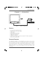
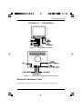
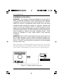
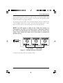
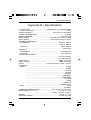
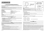
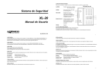
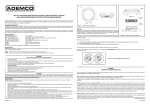
20-Inch
Black & White Monitor
Installation and Operating Instructions
AMM20
AMM20X
All information was correct at the time of publication. ADEMCO Video
reserves the right to make changes and improvements to the product without notice.
WARNING:
TO REDUCE THE RISK OF FIRE OR ELECTRIC SHOCK, DO NOT EXPOSE THIS
PRODUCT TO RAIN OR MOISTURE. DO NOT INSERT ANY METALLIC OBJECT
THROUGH VENTILATION GRILLS.
WARNING
RISK OF ELECTRIC SHOCK
DO NOT OPEN
WARNING: TO REDUCE THE RISK
OF ELECTRIC SHOCK,
DO NOT REMOVE COVER (OR BACK).
NO USER-SERVICEABLE PARTS INSIDE.
REFER SERVICING TO
QUALIFIED SERVICE PERSONNEL.
Explanation of Graphic Symbols
The lightning flash with arrowhead symbol, within an equilateral triangle,
is intended to alert the user to the presence of uninsulated “dangerous
voltage” within the product’s enclosure that may be of sufficient
magnitude to constitute a risk of electric shock to persons.
The exclamation point within an equilateral triangle is intended to alert
the user to the presence of important operating and maintenance
(servicing) instructions in the literature accompanying the product.
Safety Precautions
Should any liquid or solid object fall into the cabinet, unplug the unit and have it checked
by qualified personnel before operating it any further.
Unplug the unit from the wall outlet if it is not going to be used for several days or more.
To disconnect the cord, pull it out by the plug. Never pull the cord itself.
Allow adequate air circulation to prevent internal heat build-up. Do not place the unit on
soft surfaces (rugs, carpets, sofas, etc.) or near materials (curtains, draperies) that may block
the ventilation holes.
Height and vertical linearity controls located on the rear panel are for special adjustments
by qualified personnel only.
i
20-Inch B&W Monitor
IMPORTANT SAFEGUARDS
1. READ INSTRUCTIONS – Read the safety and operating instructions before
operating the monitor.
2. RETAIN INSTRUCTIONS – Retain the safety and operating instructions for future
reference.
3. CLEANING – Unplug video monitor from the wall outlet before cleaning. Do not use
liquid cleaners or aerosol cleaners. Use a damp cloth for cleaning.
4. ATTACHMENTS – Do not use attachments not approved by the video monitor
manufacturer as they may result in the risk of fire, electric shock or injury.
5. WATER AND MOISTURE – Do not use video monitor near water; for example, near
a bathtub, washbowl, kitchen sink, laundry tub, in a wet basement, or near a swimming pool.
6. ACCESSORIES – Do not place video monitor or equipment on an unstable cart, stand
or table. The video monitor or equipment may fall, causing serious injury and serious
damage to the equipment. Wall or shelf mounting should follow the manufacturer’s
instructions, and should use a mounting kit approved by the manufacturer.
7. CARTS – Video monitor and cart combinations should be moved with
care. Quick stops, excessive force and uneven surfaces may cause the
equipment and cart combination to overturn.
8. VENTILATION – Slots and openings in the cabinet and the back or bottom are
provided for ventilation, to ensure reliable operation of the video monitor and to protect it
from overheating. These openings must not be blocked or covered. The openings should
never be blocked by placing the video monitor on a bed, sofa, rug or other similar surface.
Video monitor should never be placed near or over a radiator or heat register. Video
monitor should not be placed in a built-in installation such as a bookcase unless proper
ventilation is provided.
9. POWER SOURCES – Video monitor should be operated only from the type of power
source indicated on the marking label. If you are not certain of the type of power supply you
have, consult your video monitor dealer or local power company.
10. GROUNDING OR POLARIZATION – This video monitor may be equipped with
a polarized alternating-current line plug (a plug with one blade wider than the other). This
plug will fit into the power outlet only one way. This is a safety feature. If you are unable
to insert the plug fully into the outlet, try reversing the plug. If the plug still fails to fit, contact
your electrician to replace your obsolete outlet. Do not defeat the safety purpose of the
polarized plug. If your video monitor is equipped with a three-wire grounding-type plug (a
plug having a third grounding pin), this plug will only fit into a grounding-type power outlet.
This is a safety feature. If you are unable to insert the plug into the outlet, contact your
electrician to replace your obsolete outlet. Do not defeat the safety purpose of the
grounding-type plug.
ii
AMM20
20-Inch B&W Monitor
11. POWER CORDS – Do not allow anything to rest on the power cord. Do not locate
video monitor or equipment where the cord can be damaged by persons walking on it.
12. HEED WARNINGS – Follow all instructions marked on the video monitor.
13. LIGHTNING – During lightning storms or when the monitor will be left unattended
and unused for long periods, unplug the monitor and associated equipment from the wall
outlet. This will prevent damage to the video equipment caused by lightning and power-line
surges.
14. OVERLOADING – Do not overload wall outlets and extension cords as this can result
in a risk of fire or electric shock.
15. OBJECT AND LIQUID ENTRY – Never push objects of any kind into video
monitor through openings as they may touch dangerous voltage points or short out parts
that could result in a fire or electric shock. Never spill liquid of any kind on the product.
16. SERVICING – Do not attempt to service video monitor as opening or removing
covers may expose you to dangerous voltage or other hazards. Refer all servicing to
qualified service personnel.
17. DAMAGE REQUIRING SERVICE – Unplug video monitor and equipment from
the wall outlet and refer servicing to qualified service personnel under the following
conditions:
A. When the power-supply cord or the plug has been damaged.
B. If liquid has spilled, or objects have fallen into the monitor.
C. If the monitor has been exposed to rain or water.
D. If the monitor does not operate normally when following the operating instructions,
adjust only those controls that are covered by the operating instructions as an improper
adjustment of other controls may result in damage and will often require extensive work
by a qualified technician to restore the monitor to its normal operation.
E. If the monitor has been dropped or the cabinet damaged.
F. When the monitor exhibits a distinct change in performance, this indicates a need for
service.
18. REPLACEMENT PARTS – When replacement parts are required, be sure the
service technician uses replacement parts specified by the manufacturer or that have the
same characteristics as the original part. Unauthorized substitutions may result in fire,
electric shock or other hazards.
19. SAFETY CHECK – Upon completion of any service or repairs to the monitor, ask the
service technician to perform safety checks to determine that the video product is in proper
operating condition.
20. FIELD INSTALLATION – Installation should be performed by a qualified service
person and should conform to all local codes.
AMM20
iii
20-Inch B&W Monitor
FCC COMPLIANCE STATEMENT
INFORMATION TO THE USER: THIS EQUIPMENT HAS BEEN TESTED
AND FOUND TO COMPLY WITH THE LIMITS FOR A CLASS B DIGITAL
DEVICE, PURSUANT TO PART 15 OF THE FCC RULES. THESE LIMITS
ARE DESIGNED TO PROVIDE REASONABLE PROTECTION AGAINST
HARMFUL INTERFERENCE IN A RESIDENTIAL INSTALLATION. THIS
EQUIPMENT GENERATES, USES AND CAN RADIATE RADIO
FREQUENCY ENERGY AND, IF NOT INSTALLED AND USED IN
ACCORDANCE WITH THE INSTRUCTIONS, MAY CAUSE HARMFUL
INTERFERENCE TO RADIO COMMUNICATIONS. HOWEVER, THERE
IS NO GUARANTEE THAT INTERFERENCE WILL NOT OCCUR IN A
PARTICULAR INSTALLATION. IF THIS EQUIPMENT DOES CAUSE
HARMFUL INTERFERENCE TO RADIO OR TELEVISION RECEPTION,
WHICH CAN BE DETERMINED BY TURNING THE EQUIPMENT OFF
AND ON, THE USER IS ENCOURAGED TO TRY TO CORRECT THE
INTERFERENCE BY ONE OR MORE OF THE FOLLOWING MEASURES:
– REORIENT OR RELOCATE THE RECEIVING ANTENNA
– INCREASE THE SEPARATION BETWEEN THE EQUIPMENT AND
RECEIVER
– CONNECT THE EQUIPMENT TO AN OUTLET ON A CIRCUIT
DIFFERENT FROM THAT TO WHICH THE RECEIVER IS CONNECTED
– CONSULT THE DEALER
TECHNICIAN FOR HELP
OR
AN
EXPERIENCED
RADIO/TV
CAUTION:
CHANGES OR MODIFICATIONS NOT EXPRESSLY
APPROVED BY THE MANUFACTURER COULD VOID THE USER’S
AUTHORITY TO OPERATE THE EQUIPMENT.
THIS CLASS B DIGITAL APPARATUS COMPLIES WITH CANADIAN
ICES-003.
CET APPAREIL NUMÉRIQUE DE LA CLASSE B EST CONFORME À LA
NORME NMB-003 DU CANADA.
THIS PRODUCT COMPLIES WITH VARIOUS OTHER REGIONAL AND
SAFETY REGULATIONS SUCH AS: UL, CUL, CSA, CE. THESE
CERTIFICATIONS ARE NOTED ON THE PRODUCT LABEL.
iv
AMM20
20-Inch B&W Monitor
Table of Contents
Chapter 1 – Introduction............................................. 1
Features ................................................................................. 1
Technical Overview ................................................................ 1
Chapter 2 – Installation ............................................... 3
Required Installation Tools ..................................................... 3
Installation Instructions ........................................................... 4
Chapter 3 – Operation................................................. 7
Appendix A – Troubleshooting ................................... 9
Appendix B – Specifications..................................... 11
List of Illustrations
Figure 1 – Typical configuration ................................................ 1
Figure 2 – Front panel controls ................................................. 3
Figure 3 – Rear panel connectors and controls ........................ 3
Figure 4 – Single monitor connection ........................................ 4
Figure 5 – Multiple monitor connection ..................................... 5
AMM20
v
20-Inch B&W Monitor
AMM20
20-Inch B&W Monitor
Chapter 1 – Introduction
Figure 1 – Typical configuration
Features
•
•
•
•
•
•
•
•
Convenient front panel controls
Switch between two video inputs
Audio input
Switchable DC restoration
Adjustable Scanning Size
LED power indicator
Video loop-through output with automatic 75-Ohm termination
Recessed carrying handles
Technical Overview
The ADEMCO AMM20 is a 20-inch B&W monitor with more than 900 TV
lines of resolution at the center. It accepts video from two sources, and the
user can switch between video sources with the simple press of a button.
Each video input has a 75-ohm BNC loop-through connector so that
additional monitors or other video equipment can be “daisy-chained” with
the monitor.
AMM20
1
20-Inch B&W Monitor
The AMM20 has a built-in speaker and audio input and output connectors
on the rear panel.
2
AMM20
20-Inch B&W Monitor
Chapter 2 – Installation
Figure 2 – Front panel controls
Figure 3 – Rear panel connectors and controls
Required Installation Tools
Installing the AMM20 monitor does not require any special tools.
AMM20
3
20-Inch B&W Monitor
Installation Instructions
WARNING: The monitor should be installed in an area that is
clean, dry and well ventilated. Do NOT install the monitor where it
can get wet; such as near pools, sinks, open windows, etc. Do NOT
install the monitor in excessively dusty areas; dust can block
ventilation holes causing the monitor to overheat. Operate the
monitor on flat firm surfaces; NOT on surfaces such as rugs,
carpet, beds or sofas because these can block ventilation holes on
the bottom of the monitor. Do NOT install the monitor where items
such as drapes or curtains can block ventilation holes. If the
monitor is installed in a rack, make certain it has sufficient
ventilation.
WARNING: If the monitor’s plug does not fit your power outlet, do
NOT modify the plug. Have a certified electrician update your
power outlet. Do NOT route the power cord where individuals can
trip on it. Do NOT route the power cord where it can be damaged
such as under a rug.
Place the monitor on a flat sturdy surface near a power outlet. Connect the
video input cable to the Video In BNC connector. The video input can be
from a camera, VCR, multiplexer or the loop output of another monitor.
Figure 4 – Single monitor connection
4
AMM20
20-Inch B&W Monitor
If the monitor will be used in a well lit area, set the DC REST (DC
Restoration) switch to the ON position. Set it to the OFF position if the
monitor is used in a low light situation.
If you plan to loop the video out to another monitor, connect a cable to the
Video Out BNC and route it to the Video In of the second monitor. Up to
three monitors can be connected using the loop-through feature.
NOTE: Do NOT attach a cable to the Video Out unless it is
connected to the Video In of another device. Attaching a cable to
the Video Out deactivates the termination and will cause poor
quality video unless the other end of the cable is attached to
another device.
Figure 5 – Multiple monitor connection
Connect the power cord to the power outlet.
AMM20
5
20-Inch B&W Monitor
6
AMM20
20-Inch B&W Monitor
Chapter 3 – Operation
To turn on the monitor, press the power button on the front panel. After a
few seconds, video should appear on the monitor. If video does not appear,
refer to the Troubleshooting section of this manual.
Press the VIDEO button to switch between the two video sources. LEDs
will light to indicate whether the A or B source is displaying.
Press the SCAN button to switch between the over-scan and under-scan
modes. When set to UNDER, the entire image from the camera displays
with some black border showing. OVER is the normal CCTV application
setting, and the picture fills the entire monitor display.
The VOLUME knob is used to adjust the audio level.
Rotate the SHARPNESS knob to adjust the picture sharpness.
Rotate the CONTRAST knob clockwise to increase picture contrast and
counterclockwise to decrease contrast.
If the picture is too dark, rotate the BRIGHT knob clockwise to brighten it.
If the picture is too bright, rotate the BRIGHT knob counterclockwise to
darken it.
If the picture is skewed, adjust the H-HOLD (horizontal hold) by rotating
the knob clockwise or counterclockwise until the picture is stationary.
If the picture rolls, adjust the V-HOLD (vertical hold) by rotating the knob
clockwise or counterclockwise until the picture is steady.
Rotate the H-SIZE knob to increase and decrease the horizontal size of the
image on the monitor display..
AMM20
7
20-Inch B&W Monitor
Rotate the V-SIZE knob to increase and decrease the vertical size of the
image on the monitor display.
8
AMM20
20-Inch B&W Monitor
Appendix A – Troubleshooting
Problem
No Video
Possible Solution
Check that all components in the system (monitor,
cameras, VCRs, multiplexers, etc.) have power and
are turned on.
Check that the camera lens cap is removed and the
lens is set to proper aperture.
Check coaxial cable(s) for proper connections and
condition.
Make certain the BRIGHT or CONTRAST control
knobs are not turned to their extreme positions.
Connect a known good video source directly to the
monitor to make certain the monitor is not the
problem.
Bad Video
Black Border
If no video equipment is “looped through” the
monitor, make certain that a cable is NOT
connected to the loop-through connector.
Set the SCAN switch to the OVER position.
Video too bright or Check position of DC REST switch.
dark
Adjust the BRIGHT knob.
Check that the lens aperture is set correctly
Bad video
Adjust the CONTRAST knob.
contrast
Skewed picture Adjust the H-HOLD knob.
Rolling picture
Adjust the V-HOLD knob.
AMM20
9
20-Inch B&W Monitor
Problem
Fuzzy Video
Possible Solution
If the camera has a manual focus lens, check that it is
properly focused.
If the camera has an autofocus lens, ensure that it is
working properly.
Check that the back focus ring on the camera has
been adjusted correctly.
Check that the lens and housing window are clean.
10 AMM20
20-Inch B&W Monitor
Appendix B – Specifications
PICTURE TUBE ....................................... 20" Diagonal, 114° Deflection Angle
(Useful screen size) ............................................................................ (18.5")
POWER SOURCE ................................................. 90 to 264 VAC, 50Hz/60Hz
POWER CONSUMPTION .................................................................. 45 Watts
VIDEO STANDARD .................................................................... EIA and CCIR
RESOLUTION ................................................. more than 900 TV lines (center)
INPUT SIGNAL .............................................. 1.0 Volt peak-to-peak (75 ohms)
SCANNING FREQUENCY:
HORIZONTAL .................................................................... 60Hz: 15.734KHz
.............................................................................. 50Hz: 15.625KHz
VERTICAL .............................................................................. 60Hz: 59.94Hz
....................................................................................... 50Hz: 50Hz
LINEARITY:
HORIZONTAL ........................................................................ 10% Maximum
VERTICAL .............................................................................. 10% Maximum
ACTIVE DISPLAY AREA:
............................................................................ 10% overscanning
............................................................................ 6% underscanning
VIDEO INPUT ...................................................................... 2 BNC connectors
VIDEO OUTPUT .................................................................. 2 BNC connectors
AUDIO
................................................ 2 RCA connectors (1 input, 1 output)
CONTROLS:
FRONT .............................................................................................. V-SIZE
.............................................................................................. H-SIZE
............................................................................................ V-HOLD
............................................................................................ H-HOLD
............................................................................................ BRIGHT
...................................................................................... CONTRAST
.................................................................................... SHARPNESS
...........................................................................................VOLUME
................................................................................................ SCAN
........................................................................................ VIDEO A/B
................................................................................ POWER Switch
BACK ................................................................................................ V-LIN
.......................................................................................... DC REST
OPERATING TEMPERATURE ............................ 32°F to 104°F (0°C to 40°C)
DIMENSIONS (W x D x H) ................................................ 17.5” x 15.0” x 16.9”
.............................................................. 445mm x 381mm x 430mm
WEIGHT ................................................................................38 lbs. (17.3 Kg)
SHIPPING WEIGHT ............................................................. 46.9 lbs. (21.3 Kg)
AMM20 11
ADEMCO Brasil
(Headquarters)
175 Eileen Way
Syosset, NY 11791
USA
1-516-921-6704
Customer Service: .............. 800-467-5875
Applications: ....................... 877-653-0302
Technical Support: .............. 877-718-0746
Fax: ..................................... 516-921-0491
Web site: www.ademco.com/ademcovideo
ADEMCO International (Headquarters)
180 Michael Drive
Syosset, NY 11791
USA
1-516-921-6704
AUSTRALIA
ADEMCO Australia
Unit 5, Riverside Centre
24-28 River Road West
Parramatta, NSW 2150
Australia
61-2-8837-9300
ASIA/PACIFIC
ADEMCO Asia Pacific
Flat A&B, 7/F, CDW Building
388 Castle Peak Road
Tsuen Wan, N.T
Hong Kong
852-2405-2323
LATIN AMERICA
ADEMCO International (Latin America)
1769 NW 79th Ave.
Miami, FL 33126
USA
1-305-477-5204
AMM20 & AMM20X
Rua Eng, Isaac Milder, 500
Sao Paulo, SP
Brasil
CEP: 05688-010
55-11-3758-6111
EUROPE
ADEMCO France
Parc Gutenberg
13, Voie La Cardon
91120, Palaiseau
France
33-1-6932-1090
ADEMCO Italia SpA
Via della Resistenza, 53/59
20090 Buccinasco - MI
Italy
39-02-457-179-1
ADEMCO Sontrix España
Vivero 5-28040
Madrid
Spain
34-91-533-4706
Security House
Amperestraat 41
1446 TR Purmerend
Netherlands
31-299-419-000
Video Controls Ltd.
Aston Fields Rd.
Whitehouse Ind. Est
Runcorn
UK WA7 3DL
44-1928-754000
AMM20Q0501