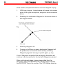
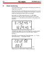
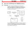
1
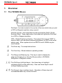
YEOMAN Sport
User Handbook
YEOMAN Sport
YEOMAN is a trademark of YEOMAN Group plc registered in the UK and USA
and applied for in the European Union.
To the best of our knowledge and belief, the information contained within this
handbook is correct and complete at the time of printing. However, YEOMAN
reserve the right to change or improve the product according to technical
developments. Any such developments will be described in addendum leaflets
supplied with the product. YEOMAN accept no liability for information contained
within this handbook which has been superseded by such addenda.
© YEOMAN 1998. All rights reserved.
1
2
YEOMAN Sport
YEOMAN Sport
3
Introduction
Brief description
The YEOMAN Sport is a portable chart plotter that provides all
the features of electronic plotting while using all the benefits of
conventional paper charts. Its full capabilities are realised
when interfaced to a GPS, LORAN or DECCA receiver, which
enables the YEOMAN Sport to show vesselís position directly
on the chart.
About this manual
This Manual covers the operation of the following YEOMAN
products:
•
YEOMAN Sport
The portable YEOMAN product for coastal navigation. It
contains pre-loaded chart libraries for UK small format
charts and for other countries.
•
YEOMAN Sport XL
A higher specification version of the YEOMAN Sport that
allows connection to suitable RADARs. The YEOMAN
Mouse is then connected to the RADAR screen.
•
YEOMAN GPS Sport XL
A self-contained ‘plug & go’ full function 12 channel GPS
that provides all YEOMAN Sport XL functions including
RADAR plotting.
Package contents
•
•
•
•
•
Portable chart table with chart cover
YEOMAN Mouse, with cable
2m long Power/Data cable (6 pin plug to bare ends)
Practice chart (part of packaging graphic)
This user handbook.
4
YEOMAN Sport
The YEOMAN Sport XL additionally contains:
• Carrying strap
• Set of pens
• Separate Power (only) cable (2 pin plug to bare ends)
The YEOMAN GPS Sport XL additionally contains:
• External GPS antenna with 9m cable and 5 pin plug
• 0.3m long Interconnect cable (6 pin plug to 5 pin socket)
instead of Power/Data cable.
When you have confirmed that all these items are present
within the package, please fill in, tear off and return the
warranty registration card at the back of this manual. This will
allow you to receive prompt and expert support if the need
arises.
Warning
The YEOMAN Sport chart plotter is a secondary navigational
instrument which relies on data entered by the Navigator as
well as primary satellite or radio navigation sources. Prudent
navigational procedures indicate that primary navigational
techniques such as visual bearings, soundings and the
computation of an estimated position must, in all cases, be
used in conjunction with secondary electronic navigational
equipment such as the YEOMAN Sport.
Disclaimer
YEOMAN and its Suppliers, Distributors and Agents shall not
be liable for accidents occurring through misuse or malfunction
of YEOMAN Sport units.
Safe compass distance
Ensure that all elements of the unit are mounted at least one
metre away from compass sensors.
YEOMAN Sport
5
Datum
When using GPS, especially on larger scale charts, it is
important to set the GPS Datum to the same as that of the
chart being used. Failure to do so will result in incorrect
position plotting.
Projection
The YEOMAN Sport will work with all Mercator projection
charts of all scales. It will also work with larger scale maps
and charts of other projections, e.g. Transverse Mercator and
Gnomonic. Small plotting errors may be apparent on nonMercator charts with a scale smaller than 1:50 000.
Patents
Patents granted in the following countries: Australia, Belgium,
Denmark, France, Germany, Holland, Hong Kong, Italy, Japan,
Luxembourg, Norway, Singapore, South Korea, Sweden,
Switzerland, UK and USA.
The YEOMAN Sport is manufactured under licence from
QUDOS BV.
Warranty terms
YEOMAN warrants the unit to be free from defect in parts,
material and workmanship for a period of 12 months from the
date of purchase, either direct or from an authorised dealer.
The benefit of this Warranty applies only to the original
purchaser. Claims may not be made more than 18 months
after despatch of the unit from our factory. Evidence of
purchase such as prompt return of the Warranty Card will be
required. This Warranty does not affect the statutory rights of
the purchaser.
6
YEOMAN Sport
YEOMAN will repair or replace, at its option, any unit in
respect of which a valid Warranty Claim shall be made on a
return to YEOMAN basis. The cost of repair or replacement
will be charged to the customer if the unit has been misused,
damaged, tampered with by unqualified personnel or suffered
severe environmental exposure including immersion in water.
European Standard EN 60945 (CE Mark)
The YEOMAN Sport meets the standards set out in European
Standard EN 60945: 1993 for marine navigational equipment,
class B.
Under exceptional circumstances (e.g. a VHF transmission
with aerial laid close to the YEOMAN Sport) it may be possible
to cause temporary malfunction of the YEOMAN. The
YEOMAN Sport will recover normal operation when the source
of the transmission is removed.
Manufacturer
The YEOMAN Sport chart plotter is manufactured by YEOMAN
who can be contacted as below:Web site
http://www.yeomangroup.plc.uk
Europe
YEOMAN
The Shipyard, Bath Road, Lymington, Hants SO41 9YL, UK
Tel. +44 (0)1590 679777
Fax +44 (0)1590 671717
Email [email protected]
USA
YEOMAN
222 Severn Avenue, Annapolis, MD 21403-2569, USA
Tel. 410 263 7335
Fax 410 263 8318
Email [email protected]
Divisions of YEOMAN Group plc
YEOMAN Sport
7
Table of Contents
1. OVERVIEW
........................................................................
9
1.1 The YEOMAN Mouse . . . . . . . . . . . . . . . . . . . . . . . . . . . . . . . . . . . . . . . . . . . . . . . . . . . . . . . . 9
1.2 Main YEOMAN modes . . . . . . . . . . . . . . . . . . . . . . . . . . . . . . . . . . . . . . . . . . . . . . . . . . . . . . . 10
1.3 YEOMAN main mode map . . . . . . . . . . . . . . . . . . . . . . . . . . . . . . . . . . . . . . . . . . . . . . . . . . 11
2. INSTALLATION
...................................................................
12
2.1 General installation notes . . . . . . . . . . . . . . . . . . . . . . . . . . . . . . . . . . . . . . . . . . . . . . . . . . . . 12
2.2 Installation . . . . . . . . . . . . . . . . . . . . . . . . . . . . . . . . . . . . . . . . . . . . . . . . . . . . . . . . . . . . . . . . . . . . 13
2.3 Power up and initial test . . . . . . . . . . . . . . . . . . . . . . . . . . . . . . . . . . . . . . . . . . . . . . . . . . . . . 14
3. DEMONSTRATION MODE . . . . . . . . . . . . . . . . . . . . . . . . . . . . . . . . . . . . . . . . . . . . . . . . . . . . . . . 15
4. BASIC OPERATIONS
............................................................
16
4.1 Keypad . . . . . . . . . . . . . . . . . . . . . . . . . . . . . . . . . . . . . . . . . . . . . . . . . . . . . . . . . . . . . . . . . . . . . . . . 16
4.2 Magnetic/True headings . . . . . . . . . . . . . . . . . . . . . . . . . . . . . . . . . . . . . . . . . . . . . . . . . . . . . 18
4.3 Default hemispheres . . . . . . . . . . . . . . . . . . . . . . . . . . . . . . . . . . . . . . . . . . . . . . . . . . . . . . . . . 18
5. CHART LIBRARY AND REFERENCING
.......................................
19
5.1 User chart library . . . . . . . . . . . . . . . . . . . . . . . . . . . . . . . . . . . . . . . . . . . . . . . . . . . . . . . . . . . . . 20
5.2 Pre-loaded chart library . . . . . . . . . . . . . . . . . . . . . . . . . . . . . . . . . . . . . . . . . . . . . . . . . . . . . . 22
5.3 Referencing the chart . . . . . . . . . . . . . . . . . . . . . . . . . . . . . . . . . . . . . . . . . . . . . . . . . . . . . . . . 23
6. YEOMAN (PLOT) MODE
.........................................................
25
7. NAVIGATION MODE . . . . . . . . . . . . . . . . . . . . . . . . . . . . . . . . . . . . . . . . . . . . . . . . . . . . . . . . . . . . . . 26
7.1 Integral GPS (YEOMAN GPS Sport XL only)
8. WAYPOINT MODE
..............................
27
................................................................
29
8.1 Manual Waypoint entry . . . . . . . . . . . . . . . . . . . . . . . . . . . . . . . . . . . . . . . . . . . . . . . . . . . . . . 30
8.2 Sending Waypoints to a GPS . . . . . . . . . . . . . . . . . . . . . . . . . . . . . . . . . . . . . . . . . . . . . . . 30
8.3 Autopilot output (YEOMAN GPS Sport XL only) . . . . . . . . . . . . . . . . . . . . . . . . . . . 31
9. DEAD RECKONING
..............................................................
34
8
YEOMAN Sport
10. SPORT XL AND GPS SPORT XL RADAR FUNCTIONS
....................
36
10.1 Overview . . . . . . . . . . . . . . . . . . . . . . . . . . . . . . . . . . . . . . . . . . . . . . . . . . . . . . . . . . . . . . . . . . . . 36
10.2 RADAR plotting . . . . . . . . . . . . . . . . . . . . . . . . . . . . . . . . . . . . . . . . . . . . . . . . . . . . . . . . . . . . . 37
10.3 RADAR troubleshooting . . . . . . . . . . . . . . . . . . . . . . . . . . . . . . . . . . . . . . . . . . . . . . . . . . . . 39
11. ADVANCED FEATURES . . . . . . . . . . . . . . . . . . . . . . . . . . . . . . . . . . . . . . . . . . . . . . . . . . . . . . . . 40
11.1 Setup mode . . . . . . . . . . . . . . . . . . . . . . . . . . . . . . . . . . . . . . . . . . . . . . . . . . . . . . . . . . . . . . . . .
11.2 Memory Reset . . . . . . . . . . . . . . . . . . . . . . . . . . . . . . . . . . . . . . . . . . . . . . . . . . . . . . . . . . . . . .
11.3 Freeze Mode . . . . . . . . . . . . . . . . . . . . . . . . . . . . . . . . . . . . . . . . . . . . . . . . . . . . . . . . . . . . . . . .
11.4 Lock mode . . . . . . . . . . . . . . . . . . . . . . . . . . . . . . . . . . . . . . . . . . . . . . . . . . . . . . . . . . . . . . . . . . .
11.5 Two position referencing . . . . . . . . . . . . . . . . . . . . . . . . . . . . . . . . . . . . . . . . . . . . . . . . . . . .
40
44
44
45
45
12. TROUBLESHOOTING . . . . . . . . . . . . . . . . . . . . . . . . . . . . . . . . . . . . . . . . . . . . . . . . . . . . . . . . . . . 46
13. DATUM LIST
.....................................................................
14. INTERFACING DETAILS
.......................................................
47
50
14.1 YEOMAN Sport . . . . . . . . . . . . . . . . . . . . . . . . . . . . . . . . . . . . . . . . . . . . . . . . . . . . . . . . . . . . . 50
14.2 YEOMAN GPS Sport XL . . . . . . . . . . . . . . . . . . . . . . . . . . . . . . . . . . . . . . . . . . . . . . . . . . . 52
14.3 RADAR data change-over switch (GPS XL and XL) . . . . . . . . . . . . . . . . . . . . . 52
15. SPECIFICATIONS
...............................................................
53
15.1 YEOMAN Sport and YEOMAN Sport XL . . . . . . . . . . . . . . . . . . . . . . . . . . . . . . . . . . 53
15.2 YEOMAN GPS Sport XL . . . . . . . . . . . . . . . . . . . . . . . . . . . . . . . . . . . . . . . . . . . . . . . . . . . 54
APPENDIX A: YEOMAN TO GARMIN GPS 12XL, 11, 111, 45
APPENDIX B: YEOMAN TO GARMIN
120, 120XL, 125, 126, 128, 130, 135, 210, 215, 220, 225,
230 & 235
APPENDIX C: YEOMAN TO PHILIPS AP8 & AP9 GPS
APPENDIX D: YEOMAN TO PC
YEOMAN Sport
1.
9
Overview
1.1 The YEOMAN Mouse
Plot Spot - the hole located in the centre of the lens which lets you plot
a GPS or Waypoint position using a pencil.
Indicator arrows - the illuminated arrows representing North, South,
East and West. These lights when illuminated will guide the Plot Spot
to a GPS or Waypoint position.
GPS - Global Positioning System. Throughout this manual “GPS” is
used to refer to all electronic positioning systems, as GPS is the most
widely used. Other systems such as DECCA and LORAN may be
used instead.
*
The Enter key. To accept data entries.
#
The Scroll key. Moves between operating modes.
/
The Range and Bearing key. This key is used to display the
range and bearing to or from the Mouse while in YEOMAN,
Navigation or Waypoint modes.
<> The Shift keys (left/right keys).
Use these keys to highlight
individual digits to allow data entry. Also use these keys to scroll
to Dead Reckoning mode.
() The Numeric keys (up/down keys).
Operation of these keys will
increase/decrease any numeric entries.
10
1.2
YEOMAN Sport
Main YEOMAN modes
1.2.1
Chart select
Used to reference a chart on the YEOMAN Sport. A chart must
be referenced before any action is possible.
1.2.2
YEOMAN (plot)
The latitude and longitude of the current Mouse position is
displayed. Ranges and bearings between points can also be
displayed.
1.2.3
Navigation
When interfaced to a GPS, its position will be displayed and the
indicator lights will point to that position on the chart. Ranges and
bearings to or from the GPS position can be displayed. Course
and speed over ground can be displayed, as can Time To Go to
any chart position.
1.2.4
Waypoint
A Waypoint can be entered and stored either directly off the chart
or manually through the keypad. It can also be transferred
directly to most GPS units. Up to 100 Waypoints can be stored
and recalled by their allocated numbers.
1.2.5
Dead reckoning
This mode allows for the calculation and plotting of Dead
Reckoning position.
1.2.6
Set-up
To set-up interfacing and other selectable parameters.
YEOMAN Sport
1.3 YEOMAN main mode map
This mode map shows the relationship between the main
YEOMAN modes.
11
12
YEOMAN Sport
2.
Installation
2.1
General installation notes
The YEOMAN Sport requires a power supply of 12V DC.
Application of overvoltage will blow an internal fuse which will
require the unit to be returned to a service dealer. It is also
advisable to fit a surge protective fuse into the 12V power
connection.
The chart table must not be cut or drilled.
The YEOMAN Mouse curly cable should not be cut or
interfered with in any way.No metal should be within 50mm of
the chart table in any direction. The active area of the chart is
approximately 50mm in from the edges. Indicator lights will
flash when the Mouse is outside this area.
The YEOMAN is reverse polarity protected and is designed
for negative earth systems. Connection to positive earth
systems should only be made by qualified personnel.
Although the YEOMAN is marinised, it should be kept clean
and dry.
Four D ring anchor points are provided to secure the chart
table.
Do not write on the chart cover with indelible pen or ballpoint.
YEOMAN Sport
13
2.2 Installation
2.2.1
YEOMAN Sport and YEOMAN Sport XL
Make the following connections:
WHITE
(A) input to YEOMAN from GPS
BLUE
(B) input to YEOMAN from GPS
GREEN
(A) output from YEOMAN to GPS
THIN BLACK
0 volts and (B) output from YEOMAN to
GPS
RED
12 volts DC power
THICK BLACK
(SCREEN)
Connect to ground or 0 volts, optional
For further information refer to Section 14.
2.2.2.
YEOMAN GPS Sport XL
Make the following connections:
Mount the GPS antenna with its base horizontal and so that it
has a clear view of the sky from horizon to horizon. The
standard antenna is supplied in flush mount configuration a pole mount kit is supplied which fits onto a standard 1”
antenna mount. Connect the GPS antenna cable to the
YEOMAN using the short Interconnect cable.
For further information refer to Section 14.
14
YEOMAN Sport
2.3 Power up and initial test
Apply power to the YEOMAN. The Mouse will emit an audible
‘beep’, the indicator lights will illuminate and text will appear on
the display.
Lift the Mouse away from the chart table and the indicator
lights will flash, put the Mouse on the centre of the chart table
and all lights will stay on. This shows that the YEOMAN is
functioning correctly and is ready for use.
YEOMAN Sport
3.
15
Demonstration mode
All you need to get YEOMAN going is 12 volts DC.
A self-demonstrator is supplied to help gain familiarity with
YEOMAN. This is set automatically when shipped and uses
the practice chart contained in the packaging graphic in the
chart case.
After power on, place the Mouse Plot Spot over the point
marked “REF 1”, and press *. Repeat for points 2 and 3.
The YEOMAN will now enter YEOMAN mode and most
functions of the YEOMAN may be used. In Navigation mode a
simulated position and velocity allows familiarity to be gained.
The YEOMAN will exit Demonstration mode the first time that
you reference a real chart. Section 11.1 describes how to reenter demonstration mode.
When Demonstration mode is set then the supplied practice
chart must be used and the four red indicator lights will flash
together every 10 seconds in all YEOMAN modes.
16
4.
YEOMAN Sport
Basic Operations
4.1 Keypad
The YEOMAN uses the four arrow keys ()<> to enter
numeric data such as Chart and Waypoint numbers, latitude
and longitude.
4.1.1 Entering Chart and Waypoint numbers
When selecting any of these numbers, the right hand digit will
flash, indicating that you can enter or change a number.
For example, to enter the chart number 34:
S004
Press (. The flashing digit will increase by 1. If you press
and hold (, the number will increment until it reaches 9, and
then start counting again from 0. The ) key reduces the
flashing digit by 1.
YEOMAN Sport
17
Press ( until the display reads:
S005
Press <. The left hand digit will start to flash.
S006
Press ( to change the number to 3.
When the correct number is displayed, press * to accept.
18
YEOMAN Sport
4.1.2 Entering latitude and longitude
Latitude and longitude are entered and displayed in degrees,
minutes and decimal minutes (2 places).
When a latitude and longitude need to be entered, the first
digit of latitude will flash.
S007
Enter the latitude using the () and <> keys. Use
to set N/S flashing then use ( to toggle as required.
>
Press > until the first digit of longitude is flashing.
Enter the longitude using the () and <> keys.
To enter a longitude with degrees greater than 99º press )
when the leftmost zero is flashing.
Use > to set E/W flashing then use ( to toggle as required.
Press * to confirm and enter the numbers.
4.2
Magnetic/True headings
All bearings are normally displayed as magnetic. The Setup
section 11.1 describes how to change this to true.
4.3
Default hemispheres
The default hemisphere for entry of all latitude and
longitude is determined by that set in reference position 1 of
User Chart 00.
YEOMAN Sport
5.
19
Chart library and referencing
Before using YEOMAN, a chart must be entered into the
CHART LIBRARY and referenced. This requires the entry of
the latitude and longitude of three positions on the grid
intersections as below. The positions should be as far apart as
practicable and marked clearly.
THE LATITUDE OF POSITION 2 MUST BE THE SAME AS
THAT OF POSITION 1. THE LONGITUDE OF POSITION 3
MUST BE THE SAME AS THAT OF POSITION 2.
IF THE CHART MOVES ON THE CHART TABLE AFTER
REFERENCING IT MUST BE RE-REFERENCED.
Position 1 and Position 2 must be further than 50mm apart.
It is possible to reference a chart with only two reference
positions and this is described in Section 11.5.
For units shipped in the USA with the BBA Chartkit library then
Positions 1, 2 and 3 are replaced by Positions A, B and C.
20
YEOMAN Sport
Should a chart need to be overwritten at any stage, in chart
select mode hold down * for six beeps. The position entry
facility is displayed and the latitude and longitude of the
positions can be altered.
YEOMAN can be used with any general chart providing that
first three reference points are entered as in 5.1 below. Once
entered these points are stored and build a library of User
Charts.
Some chart publishers are adding special pre-plotted
YEOMAN reference points to charts to make these even
easier to use with YEOMAN, again entering these as in 5.1
below. Similarly once entered these points are stored.
For some of these pre-plotted charts YEOMAN pre-load a
library in the YEOMAN Sport. Details of which such preloaded charts are in your unit are contained in a
supplementary card with this handbook.
If the chart you are using has pre-printed reference points and
is in the list on the supplementary card then go to Section 5.2.
Otherwise follow the instructions below.
5.1
User chart library
The display should flash:
SO42
If not use () to get the display then accept with *.
YEOMAN Sport
21
Select three reference points on the chart, mark them clearly,
and number them P1, P2 and P3.
Allocate a user chart library number (00-99) and write it on the
edge of the chart for future reference. At the ‘Select Chart’
display, use the <>() keys to select the chart number.
S011
If you select a chart number which has already been used the
display reads:
S008
Press * to accept the chart number.
The display then shows P1 (Position 1). The first digit of
latitude will flash.
22
YEOMAN Sport
S007
Enter the latitude and longitude for P1, ensuring that N/S and
E/W are entered correctly (see Section 4.1.2).
Press * to accept Position 1 (P1).
Enter the latitude and longitude for Position 2 (P2) and
Position 3 (P3) in the same way.
If a mistake is made during the entry of any of the positions
press # and then hold * down for six beeps. The display will
revert back to the position entry facility where the latitude and
longitude of the positions can be edited.
Now go direct to Section 5.3.
5.2
Pre-loaded chart library
Use ( to get the display flashing the YEOMAN design-nation of
the pre-loaded library that you wish to use. For instance for
UK Admiralty Small Craft Edition scroll until
SO43
is displayed flashing.
YEOMAN Sport
23
For Chartkit library scroll until
SO44
is displayed flashing.
Select the pre-loaded library with *.
Select the chart set required. For example with UK Admiralty
charts select Folio 5600, 5604 etc. using (. For Chartkits,
select the Region using (.
Select chart number in series required (see Section 4.1.1).
5.3
Referencing the chart
The display will now read:
S009
Align the Plot Spot over chart reference Position 1. Press *.
Repeat action for Positions 2 and 3.
During referencing the latitude and longitude of the reference
points can be displayed by pressing (.
24
YEOMAN Sport
If the chart has been referenced correctly the YEOMAN will
advance to YEOMAN (PLOT) mode after Position 3 has been
accepted. A quick check of the referencing should be made on
a suitable point (such as another grid position) and the display
should be compared with a chart position.
If the referencing has been done incorrectly the indicator
arrows flash and the display shows:
S013
In this case there has been one of:
•
Incorrect positioning of the Mouse or chart moved during
referencing. Press # to return to chart referencing and
then reference again carefully.
Or
•
Incorrect or inconsistent latitude/longitude of one or more
of the reference positions. Press # to return to chart
referencing and re-reference, this time displaying the
latitude and longitude of the reference points by using (,
as described earlier. Specifically check N/S and E/W
entries are correct and that P1 and P2 are more than
50mm apart.
Or
•
One of the reference points is outside the active area.
The indicator lights will flash when over the position.
Select a new reference point or re-position chart.
Depending on the result either correct the reference position
latitude and longitude as described earlier, or mark corrected
reference positions on the chart.
YEOMAN Sport
6.
25
YEOMAN (plot) mode
This mode is used for normal chart work and for obtaining
range and bearing between points.
The YEOMAN goes to this mode when referencing is
completed; or press # until YE appears on the display.
S014
The display will now indicate the latitude and longitude of the
Plot Spot position as the Mouse is moved.
To memorise a chart position place the Plot Spot over it and
press *, the indicator arrows extinguish.
This action also outputs a ‘GLL’ position on the NMEA 0183
output line.
Press / to get Range and Bearing to anywhere on the chart
the Mouse is placed from the memorised position.
S015
Toggle to the reciprocal bearing by pressing ). Holding down
the ( displays the reciprocal bearing Press / to return to
latitude/longitude display.
The illuminated arrows will show the direction to the
memorised point.
26
7.
YEOMAN Sport
Navigation mode
This mode allows the current position from a GPS to be plotted
directly on to the chart. Scroll with # to Navigation (NA)
mode.
If the indicator arrows flash the YEOMAN is not receiving valid
data from the GPS. Refer to Section 14.
The latitude and longitude of the GPS position is displayed,
and is updated every few seconds.
S017
One or two of the indicator arrows will illuminate and point to
the position on the chart. Move the Mouse in the direction the
arrows indicate until they are all extinguished. The Plot Spot is
now over the GPS position, and this can be plotted using a
pencil through the Plot Spot hole.
Press / to get Range and Bearing to anywhere on the chart
the Mouse is placed from the current GPS position in a similar
way to that in YEOMAN mode.
Press ( to display Course over Ground (CO) and Speed over
Ground (SP), in knots, from the GPS.
YEOMAN Sport
27
S018
Press ( to display Time to Go (tt GO). This will show the time
to go in hours and minutes from shipís position to the Plot Spot
at the current speed over ground. The calculation does not
take into account current course.
S019
7.1
Integral GPS (YEOMAN GPS Sport XL only)
All GPS information is displayed in the (NA) Navigation page.
If no fresh GPS data is available, then the last good position
will be shown and all indicator lights will flash.
Pressing the ) key will then display the first GPS display
page:
S020
28
YEOMAN Sport
The upper line indicates the number of satellites currently in
view. This will normally be zero or a small number when the
unit is first turned on and then increase as satellites are found.
If the upper line shows ‘-’ then this indicates that no data is
being received from the GPS antenna. Check all connections
and if necessary contact a service dealer. If a zero or any
other number is shown then this indicates that data is being
received.
The lower line shows the mode of navigation. 0d indicates no
fix available while two and three dimensional fixing are
indicated by 2d and 3d respectively.
The second GPS page is accessed with a further press of the
) key:
S021
Now the first line shows GPS time in Universal Time
(effectively GMT).
The lower line shows the Horizontal Dilution of Position (1-99)
which is a measure of quality of fix (lower number means
higher geometric quality).
Pressing ( twice steps back through the first GPS page to
the Navigation display.
YEOMAN Sport
8.
29
Waypoint mode
Waypoints can be entered directly from the chart, or manually
using the Mouse keys. The YEOMAN will also send the
Waypoint information to a GPS receiver.
Press # to scroll to WAYPOINT mode.
Select the Waypoint position on the chart and allocate a
number (00-99) from the Waypoint Library. Mark the Waypoint
on the chart and write the number beside it in pencil.
S022
Set in Waypoint number using ()<>. Place the Plot Spot
on the Waypoint position on the chart and press * to enter.
The Waypoint is entered and in the Waypoint library. The
indicator arrows extinguish and the latitude and longitude of
the Waypoint position are displayed.
S023
30
YEOMAN Sport
When the Mouse is moved, one or two indicator arrows will
illuminate and point to the Waypoint position on the chart.
Waypoints already stored are overwritten if a new position is
entered using the same number. If an existing Waypoint is
accessed, its position will appear on the display and the
indicator arrows will show its position. Consequently a
Waypoint stored in the Waypoint library can be transferred
from chart to chart.
Press / to get Range and Bearing to anywhere on the chart
the Mouse is placed from the current Waypoint position in a
similar way to that in YEOMAN mode.
8.1
Manual Waypoint entry
To manually enter a Waypoint set the Waypoint number
then press * and hold down for six beeps. Set in the
latitude and longitude of the Waypoint, as in Section 4.1.2.
Press * to accept Waypoint.
8.2
Sending Waypoints to a GPS
8.2.1 General
When a Waypoint is entered into the YEOMAN its number and
position is transmitted to the GPS via the NMEA 0183 output.
A GPS with a suitable NMEA 0183 input capability will be able
to accept the Waypoints directly from the YEOMAN.
YEOMAN Sport
31
8.2.2 Special considerations
There are a few important points to consider when sending
Waypoints to a GPS and some checks are worthwhile:
8.3
•
Is the GPS capable of receiving Waypoints from another
piece of equipment? Does it have an input port and, if
so, does it accept the correct data? Please consult your
GPS handbook, your dealer or YEOMAN.
•
•
Are the connections correct? Refer to Section 14.
•
Some GPS do not change the displayed Waypoint on
entry from YEOMAN. Scroll the GPS display away from
Waypoint entered and then scroll back to view the new
Waypoint position.
•
•
Waypoint 00 is never transmitted.
Some GPS allow their Waypoints to be overwritten - in
the same way as YEOMAN does and some do not.
The YEOMAN can be set to append 100 to 900 to
Waypoint numbers (i.e. Waypoint 12 can be sent as 112)
to write into specific Waypoint banks on some GPS units.
See Section 11.1.1 for details.
Autopilot output (YEOMAN GPS Sport XL only)
Provided that the YEOMAN GPS Sport XL is receiving position
then output is sent out to drive an autopilot.
To do this set or select an end Waypoint with number anything
except 00. Once this destination Waypoint is selected then
use the # key to move on from the Waypoint page. At this
point the run-line to be followed is set between the current
GPS position and the selected destination Waypoint. Autopilot
information will then start to be transmitted while the GPS is
still obtaining a valid fix.
32
YEOMAN Sport
Once started, autopilot data will be sent and stopped only by:
1.
GPS loss of signal. Autopilot data will cease, but resume
when GPS signal re-acquired, subject to other conditions
below.
2.
Reaching the destination Waypoint in the sense shown in
the diagram below:
Fig83
3.
Selecting Waypoint 00.
4.
Turning unit off then on again, destination Waypoint will
be preserved, but must be reactivated by selecting
Waypoint page and moving on past it again, # key.
If a ‘null’ Waypoint is selected then autopilot information will
continue to be transmitted to the last valid Waypoint selected.
When valid autopilot data is being transmitted then the
Navigation (NA) and YEOMAN (YE) display pages will have
the WAYPOINT flag in the centre of the LCD display showing.
YEOMAN Sport
33
On the Waypoint page, it is possible to scroll through and enter
Waypoints other than the current destination Waypoint without
disturbing the autopilot output. The TO flag on the upper edge
of the LCD display will show on the destination Waypoint only.
If the position of the current destination Waypoint is changed,
then the output to the autopilot changes immediately to the
new position from current GPS position. This gives the
powerful ‘point and go’ method of driving an autopilot. If a
Waypoint other than the current destination is selected when
the Waypoint page is left then this new point will become the
destination, starting from the current GPS position.
No facility for holding routes is provided. When a Waypoint is
reached, select the next point by setting the Waypoint either
from the library or by putting the Mouse over next destination
point and updating current Waypoint (pressing *).
To disable output select Waypoint 00.
There is no display of cross-track offset as this can very simply
be picked off the chart using the normal YEOMAN plotting
facilities.
34
9.
YEOMAN Sport
Dead reckoning
This mode allows for the calculation and plotting of position by
Dead Reckoning (DR).
If the Tidal Direction and Rate are input as well as Course and
Speed then these will be included in the calculation in order to
enable an Estimated Position (EP) to be plotted.
Scroll with # to NA mode and press > to DR Mode.
Place the Plot Spot on ship’s current position on the chart
and press *. The latitude and longitude of the position are
displayed.
S025
YEOMAN will update this and the DR position can be plotted
using the indicator arrows, as in the NA mode. Refer to
Section 7.
To set DR Course, Speed and Tidal data press #. To exit
DR mode press <. The display shows:
S026
Using <>() set course. Press * to accept.
YEOMAN Sport
35
If there is an NMEA 0183 sentence “VHW” from the compass
and log then course and speed will automatically up-date.
Display shows:
S027
Using ()<> set speed. Press * to accept.
The display shows:
S028
Using ()<> set water current direction and velocity.
Press * to accept.
Press # to return to DR mode and then press < to exit DR
mode and return to NA mode.
At any time DR/EP position can be updated by placing the Plot
Spot over an updated fixed position and pressing * while in
DR mode.
36
YEOMAN Sport
10.
Sport XL and GPS Sport XL RADAR functions
10.1
Overview
A number of small boat RADARs have a feature which
displays as a ‘lollipop’ the next Waypoint in a sailplan from a
GPS. These RADARs can, in general, also be connected to
the Sport XL versions. The general arrangement of the
connections is shown below:
Fig101
To use YEOMAN input and GPS input a changeover switch is
needed as the RADAR cannot accept two inputs at the same
time. Such a switch (DATABOX) is available from YEOMAN or
can be made as in Section 14.3.
YEOMAN Sport
37
When the RADAR input is set to the YEOMAN, the ‘lollipop’ on
the RADAR will track the position of the YEOMAN mouse on
the chart, see Section 10.2 below. An electronic compass
input is needed for the RADAR to enable this. Note that
Course Over the Ground input from a GPS cannot be used in
the place of a compass.
10.2
RADAR plotting
Set the YEOMAN into Navigation Mode, see Section 7, and
then display range/bearing using the / key and then:
•
Press the * key once to send a snap-shot of the Mouse
position to the RADAR. Note that this does not
automatically update. Further presses of the * key are
needed to update new range and bearing to the RADAR.
•
Alternatively, hold the * key down for five beeps and
then release it. The YEOMAN then streams
range/bearing data to the RADAR continuously from the
Mouse position wherever it is moved. There may be a
slight delay in the response of the RADAR ‘lollipop’,
which varies with RADAR model and manufacturer.
As soon as range/bearing display is changed, then output to
the RADAR ceases. A short period later the RADAR ‘lollipop’
display will then disappear and ‘no data’ may be flashed
(dependent on RADAR used).
RADAR plotting will also function in a similar way from DR
mode, Section 9.
The YEOMAN RADAR plotting system does nothing more nor
less than replicate a manual plot, with the exception of being
easier, quicker and less prone to manual plotting error. The
sources of error are thus the same and fall into the following
categories:
38
YEOMAN Sport
RADAR misalignment
Common to manual or YEOMAN plotting. See RADAR
handbook or any book on RADAR for techniques on how to
resolve and rectify this.
Compass misalignment or calibration error
Potentially an area where manual plotting, probably using the
main steering compass, and YEOMAN plotting, based on the
RADAR’s electronic compass, may differ.
A careful check of the electronic compass used for the RADAR
against a properly swung primary compass, taking account of
the deviation card, should be made on all compass headings.
This should be checked from time to time, especially after any
refit, in case the electronic compass sensor should have been
disturbed or any change to its magnetic environment occurred
(e.g. electrical equipment or magnetic material placed nearby).
Navigation system error
Common to either methods and the user should always remain
alert to the fact that the electronic position data may be in error
or may not tie up to the co-ordinates on the chart. Remedies
include:
•
a second independent electronic navigation system (i.e.
use both GPS and DECCA or LORAN) and compare
regularly
•
regular checking against conventional navigation
including dead reckoning, depth sounder and compass
bearings on known features
•
checking against RADAR, for which the YEOMAN
plotting system is particularly convenient.
YEOMAN Sport
39
Plotting position error
Both manual and YEOMAN position plotting can be
checked by the same methods as above. The likeliest
form of error with the YEOMAN is movement of the chart
since it was last referenced. If in any doubt it is sensible
to re-reference, which takes but a few seconds, before
plotting.
It is suggested that after initial installation, a careful check
against a manual plot and known scenario (e.g. vessel held in
marina berth with well identified RADAR targets such as
channel markers). Regular checks against well identified
targets in good conditions will assist both with functional
familiarity and with confidence and reliability assessment when
needed under more testing conditions.
10.3
RADAR troubleshooting
If the RADAR ‘lollipop’ cannot be initiated by setting the
YEOMAN into RADAR plotting mode, a suggested list of
symptoms and tests is given below:
a)
Ensure that RADAR is receiving compass data and is set
in magnetic compass ‘mode’. The RADAR will not
accept range/bearing data and plot the ‘lollipop’
otherwise. Check the compass and interfacing to the
RADAR.
b)
If the RADAR is accepting compass data then remaining
areas to check areselection of Waypoint plotting mode on RADAR, see
manufacturer’s handbook
interfacing to the RADAR. Check this by linking the GPS
directly to the RADAR to see if conventional GPS
RADAR Waypoint plotting is working.
40
YEOMAN Sport
11.
Advanced features
11.1
Setup mode
Press the # button repeatedly until you get to Chart
Referencing mode. Press / to enter Setup mode. Press *
to step between setup screens in the following order:
•
•
•
•
•
•
•
GPS Datum (YEOMAN Sport GPS XL only)
Year
True/Magnetic selection
Clear Waypoints
GPS interface
Waypoint prefix
Demonstration mode selection.
11.1.1 GPS datum (YEOMAN GPS Sport XL only)
S041
This shows that the GPS Datum is number 100 (WGS 84).
You can change the Datum using the ( and ) buttons.
Refer to Section 13 for a list of datum code numbers.
YEOMAN Sport
41
11.1.2 Year
Use the ()<> keys to enter the current year.
S039
This is used to calculate magnetic variation.
11.1.3 True/Magnetic selection
This option lets you change the heading definition.
S038
Yes or No can be selected using the < or > keys.
YES tells the YEOMAN to use True headings.
NO selects automatic magnetic variation.
Press * to enter your choice.
42
YEOMAN Sport
11.1.4 Clear Waypoints
This option clears ALL Waypoints stored within the YEOMAN
memory.
S030
To clear the Waypoints, press < to select Yes, and then press
*. Otherwise, select No and press *.
11.1.5 GPS interface
The default GPS interface works with the majority of GPS
receivers. This function selects for specific GPS units.
S033
00
Default, Standard NMEA 0183 - suits most receivers
01
Magellan 3000 XL
02
MLR Valsat SP
03
MLR Valsat 2008
04
Trimble NT series
Additional information on GPS types may be on a card packed
with the handbook.
YEOMAN Sport
43
11.1.6 Waypoint prefix
S040
This adds a number to the Waypoint output only.
For example if the prefix is set to 200 then YEOMAN Waypoint
73 will be output to the GPS as Waypoint number 273. This
allows use of multiple Waypoint banks in some GPS units.
11.1.7Demonstration mode selection
The display will show:
S035
Select Yes or No using <> then press *.
When Demonstration mode is set then the supplied practice
chart must be used and the four red indicator lights will flash
together every 10 seconds in all YEOMAN modes.
44
11.2
YEOMAN Sport
Memory Reset
This function resets the YEOMAN to its factory defaults.
ALL INFORMATION YOU HAVE INPUT WILL BE LOST,
INCLUDING CHARTS AND WAYPOINTS. THE PRELOADED CHART LIBRARY WILL NOT BE DELETED.
To reset the YEOMAN to its factory defaults, hold down ) and
switch on the power. Keep the key depressed until the display
reads:
S031
Press < to select Yes, and then press *. Turn the power off
again. When you next turn the power on the unit will have
been reset to its factory defaults.
11.3
Freeze Mode
It is possible to freeze the display while operating the Range
and Bearing facility by holding down > for five beeps. This
allows the Mouse to be picked up and the display read without
alteration. To unfreeze the display press <.
YEOMAN Sport
11.4
45
Lock mode
Whilst in Navigation mode, pressing * for two beeps locks the
YEOMAN in Navigation mode, while still allowing different
modes such as Satellite Info, Range and Bearing, manual
Dead Reckoning, Course, Speed Over Ground and Time To
Go to be accessed.
When in Lock mode the NA flag in the centre of the screen
changes to NL.
Press of * for one beep or a single press of # unlocks the
lock mode.
11.5
Two position referencing
The YEOMAN will operate with only two reference positions by
referencing Positions 1 and 2 normally and then by referencing
Position 3 on the same point as Position 2.
This method of chart referencing allows the use of small charts
and insets where it might be difficult to find three suitable
reference positions. It also enables the creation of a large
scale Mercator plotting sheet.
REFERENCING ON TWO POSITIONS PROVIDES NO
REFERENCING CHECK AND MAY RESULT IN SMALL
INACCURACIES. USE THIS METHOD WITH CAUTION.
46
YEOMAN Sport
12.
Troubleshooting
Problem
Possible cause
Suggested action
NO RESPONSE. NO
DISPLAY OR
BACKLIGHT.
A) No external power
supply.
B) Blown internal fuse.
A) Check battery voltage.
Check polarity (red +12V, thin
black 0V) Check any external fuse.
B) Return to service dealer.
UNIT COMES ON
AND THEN SCREEN
BLANKS OR LOCKS
UP.
A) Low voltage or
corrupted data being
transmitted to
YEOMAN.
A) Check battery voltage.
Temporarily disconnect input
data cable.
YEOMAN DOES NOT
REFERENCE
CORRECTLY.
A) Incorrect reference
positions.
B) Reference positions
outside active area.
C) Reference positions
too close.
A) Check Lat/Long of reference
positions.
B) Check positions are within the
active area of the chart table.
C) Check P1 and P2 are more than
50mm apart.
YEOMAN SPORT
PLOTS INACCURATE
POSITION.
A) Unit corrupted by
A) Check that there is no metal near
metal.
YEOMAN Sport.
B) Chart has moved.
B) Fix chart and re-reference.
C) GPS input is defective. C) Check connections, interface and
Datum are correct.
YEOMAN LIGHTS
A) YEOMAN not
FLASH IN NAVIGATION
receiving position
MODE.
A) Check GPS specification.
Check connections.
YEOMAN DOES NOT
RETAIN REFERENCE
POSITIONS.
A) Return to service dealer or
YEOMAN.
A) Internal battery flat
YEOMAN LIGHTS
A) In Demo mode
FLASH AT TEN
SECOND INTERVALS.
A) See Section 3 and 11.1.7.
YEOMAN Sport
13.
INDEX
0
1
2
3
4
47
Datum list
DATUM EARTH NAME
ADINDAN
AFGOOYE
AIN EL ABD 1970
ANNA 1 ASTRO 1965
ARC 1950
AREA OF APPLICATION
Ethiopia, Mali, Senegal, Sudan
Somalia
Bahrain island, Saudi Arabia
Cocos Island
Botswana, Lesotho, Malawi,
Swaziland, Zaire, Zambia, Zimbabwe
Kenya, Tanzania
Ascension Island
Iwo Jima Island
Australia, Tasmania Island
Australia, Tasmania Island
St Helena Island
Marcus Island
Tern Island
Efate and Erromango Islands
Bermuda Islands
Colombia
Argentina
Phoenix Islands
Florida, Bahama Islands
South Africa
Tunisia
Chatham Island (New Zealand)
Paraguay
Brazil
Sumatra Island (Indonesia)
Gizo Island (New Georgia Islands)
Easter Island
Austria, Belgium, Denmark, Finland,
France, Germany, Gibraltar, Italy,
Greece, Luxembourg, Netherlands,
Norway, Portugal, Spain, Sweden,
Switzerland
Austria, Finland, Netherlands,
5
6
7
8
9
10
11
12
13
14
15
16
17
18
19
20
21
22
23
24
25
26
27
ARC 1960
ASCENSION ISLAND 1958
ASTRO BEACON “E”
AUSTRALIAN GEODETIC 1966
AUSTRALIAN GEODETIC 1984
ASTRO DOS 71/4
ASTRONOMIC STATION 1952
ASTRO B4 SOROL ATOLL
BELLEVUE (IGN)
BERMUDA 1957
BOGOTA OBSERVATORY
CAMPO INCHAUSPE
CANTON ASTRO 1966
CAPE CANAVERAL
CAPE
CARTHAGE
CHATHAM 1971
CHUA ASTRO
CORREGO ALEGRE
DJAKARTA (BATAVIA)
DOS 1968
EASTER ISLAND 1967
EUROPEAN 1950
28
EUROPEAN 1979
Norway, Spain, Sweden, Switzerland
FINLAND HAYFORD 1910
Finland
GANDAJIKA BASE
Republic of Maldives
GEODETIC DATUM 1949
New Zealand
ORDNANCE SURVEY OF GREAT England, Isle of Man, Scotland, Shetland
BRITAIN 1936
Islands, Wales
29
30
31
32
33
GUAM 1963
Guam Island
48
YEOMAN Sport
34
35
36
37
38
39
40
41
42
43
44
45
46
47
48
49
50
51
52
53
54
55
56
GUX 1 ASTRO
HJORSEY 1955
HONG KONG 1963
INDIAN
INDIAN
IRELAND 1965
ISTS 073 ASTRO 1969
JOHNSTON ISLAND 1961
KANDAWALA
KERGUELEN ISLAND
KERTAU 1948
LC 5 ASTRO
LIBERIA 1964
LUZON
LUZON
MAHE 1971
MARCO ASTRO
MASSAWA
MERCHICH
MIDWAY ASTRO 1961
MINNA
NORTH AMERICAN 1927
NORTH AMERICAN 1927
57
NORTH AMERICAN 1927
58
59
60
NORTH AMERICAN 1927
NORTH AMERICAN 1927
NORTH AMERICAN 1927
61
62
63
64
65
66
NORTH AMERICAN 1927
NORTH AMERICAN 1927
NORTH AMERICAN 1927
NORTH AMERICAN 1927
NORTH AMERICAN 1927
NORTH AMERICAN 1983
67
68
69
70
71
72
NAPARIMA, BWI
NAHRWAN
NAHRWAN
NAHRWAN
OBSERVATORIO 1966
OLD EGYPTIAN
Guadalcanal Island
Iceland
Hong Kong
Bangladesh, India, Nepal
Thailand, Vietnam
Ireland
Diego Garcia
Johnston Island
Sri Lanka
Kerguelen Island
West Malaysia, Singapore
Cayman Brac Island
Liberia
Mindanao Island
Phillippines (excluding Mindanao Island)
Mahe Island
Salvage Islands
Eritrea (Ethiopia)
Morocco
Midway Island
Nigeria
Alaska
Bahamas (excluding San Salvador
Island)
Central America (Belize, Costa Rica, El
Salvador, Guatemala, Honduras,
Nicaragua)
Canal Zone
Canada (including Newfoundland Island)
Caribbean (Barbados, Caicos Islands,
Cuba, Dominican Republic, Grand
Cayman, Jamaica, Leeward Islands,
Turks Islands
Mean Value (CONUS)
Cuba
Greenland (Hayes Peninsula)
Mexico
San Salvador Island
Alaska, Canada, Central America,
CONUS, Mexico
Trinidad and Tobago
Masirah Island (Oman)
Saudi Arabia
United Arab Emirates
Corvo and Flores islands (Azores)
Egypt
YEOMAN Sport
73
74
75
76
77
78
79
80
81
82
83
84
OLD HAWAIIAN
OMAN
PICO DE LAS NIEVES
PITCAIRN ASTRO 1967
PUERTO RICO
QATAR NATIONAL
QORNOQ
REUNION
ROME 1940
RT 90
PROVISIONAL SOUTH
AMERICAN 1956
SOUTH AMERICAN 1969
49
Mean Value
Oman
Canary Islands
Pitcairn Island
Puerto Rico, Virgin Islands
Qatar
South Greenland
Mascarene Island
Sardinia Island
Sweden
Bolivia, Chile, Colombia, Ecuador,
Guyana, Peru, Venezuela
Argentina, Bolivia, Brazil, Chile,
Colombia, Ecuador, Guyana, Paraguay,
Peru, Venezuela, Trinidad, Tobago
Singapore
South Chile
85
86
SOUTH ASIA
PROVISIONAL SOUTH
CHILEAN 1963
87
88
89
90
91
92
SANTO (DOS)
SAO BRAZ
SAPPER HILL 1943
SCHWARZECK
SOUTHEAST BASE
SOUTHWEST BASE
93
TIMBALAI 1948
94
95
96
TOKYO
TRISTAN ASTRO 1968
NOT USED
97
98
99
VITI LEVU 1916
Viti Levu Island (Fiji Islands)
WAKE-ENIWETOK 1960
Marshall Islands
WORLD GEODETIC SYSTEM 1972
100
101
102
103
104
105
106
107
WORLD GEODETIC SYSTEM 1984 System default
ZANDERIJ
Surinam
CH-1903
Switzerland
HU-TZU-SHAN
INDONESIA 1974
Indonesia
AUSTRIA
Austria
POTSDAM
Germany
TAIWAN (MODIFIED HU-TZU-SHAN) Taiwan
Espirito Santo Island
Sao Miguel, Santa Maria Islands (Azores)
East Falkland Island
Namibia
Porto Santo and Madeira Islands
Faial, Graciosa, Pico, Sao Jorge, and
Terceira Islands (Azores)
Brunei and East Malaysia (Sarawak and
Sabah)
Japan, Korea, Okinawa
Tristan da Cunha
50
14.
YEOMAN Sport
Interfacing details
Interfacing uses standard NMEA 0183 sentences. Some
manufacturers have introduced variants which require a setting
as in Section 11.1.5.
Details of connections to sample GPS units are at the end of
this Handbook. Datasheets on most GPS and other units are
held by YEOMAN and available from them, a dealer or the
YEOMAN website.
An optional Power input cable and connector (2-pin) may be
used. This is connected internally in parallel to the power
elements (red and thin black) of the Power/Data cable.
When power is supplied, say from a cigarette lighter socket, on
the Power input connector then power may be taken off the
(red and thin black) elements of the Power/Data cable, for
instance to provide power to a hand-held GPS.
In the following diagrams, power input is shown on the
Power/Data cable unless otherwise stated.
14.1
YEOMAN Sport
If the GPS has a two wire output, i.e. Data out A (or +) and
Data out B (or -) then connect Data out A to the YEOMAN
White and Data out B to the YEOMAN blue.
YEOMAN Sport
51
If the GPS has a single wire output (Data out) then connect
this to the YEOMAN white. The YEOMAN blue is in these
cases connected to 0 volts i.e., the same point as the
YEOMAN thin black.
If the GPS has a two wire input, i.e. Data In A (or +) and Data
In B (or -), then connect Data In A to the YEOMAN green.
Data In B will need to be connected with a link wire to 0 volts
i.e., the same point as the YEOMAN thin black.
If the GPS has a single wire input, (Data In) then connect this
to the YEOMAN green.
14.1.1 YEOMAN Sport XL RADAR connections
The NMEA 0183 data out can be connected to a RADAR.
52
14.2
YEOMAN Sport
YEOMAN GPS Sport XL
Standard connections are shown in Section 2.2.2. In order to
connect a RADAR or autopilot it is necessary to break into the
interconnect cable, which may be extended as necessary. The
following diagram gives guidance on the connections; power
input via the Power cable is not shown.
The NMEA 0183 data out can be connected either to an
autopilot or to a RADAR.
14.3
RADAR data change-over switch (GPS XL and XL)
To allow normal Waypoint plotting and YEOMAN Waypoint
plotting a change-over switch on the input to the RADAR
should be fitted as follows:
YEOMAN Sport
53
15.
Specifications
15.1
YEOMAN Sport and YEOMAN Sport XL
Power supply
10-15 volts DC, 250mA
Operating temperature
0-45 C
Display (on Mouse)
LCD, 90 viewing angle
Function controls
7 tactile keys
Illumination
LCD backlighting and chart light
Overall dimensions
675 x 495 x 50 mm
Active area
515 x 380 mm
Weight
2.4 kg
Plotter resolution
Better than 2mm
Chart projections
Mercator and port plans
Chart library
100 User charts, 100 Waypoints
Waypoint library
100 Waypoints
Memory retention
Minimum 36 months
External NMEA 0183
interface
4800 Baud, 8 data bits, 1 stop bit, no parity
Output: TTL levels (0V and 5V)
Input:opto-isolated,0V and 2V(min) to 20V (max)
Maximum reverse voltage 20V
Maximum current requirement: 50mA (at +20V)
Input (NMEA 0183)
Sentences: GGA, RMC, GLL, VTG, VHW
Prioritised in order shown
Sentences: WPL
GLL on * key in YEOMAN mode
VTG, BWC - Sport XL only, RADAR plotting
Output (NMEA 0183)
o
o
54
15.2
YEOMAN Sport
YEOMAN GPS Sport XL
The specifications for the YEOMAN GPS Sport XL are the same as for the
YEOMAN Sport XL except for the following:
Power consumption
300 mA, normal operating mode
GPS antenna dimensions
57 x 97 x 37mm
GPS antenna weight
0.125 kg
Chart datums
101
GPS Receiver
Tracks and uses up to 12 satellites
Output (NMEA 0183)
Sentences: As YEOMAN Sport XL, plus GGA,
RMC, XTE
Time to fix:
Reacquisition
Less than 2 seconds
Warm
15 seconds, all data known
Cold
45 seconds, position, time and almanac known
Sky search
5 minutes, no data known
Update rate
1 second
Accuracy
15 metres RMS, reduced to 100 metres 2 DRMS
with Selective Availability (SA)
YEOMAN Sport
55
Appendix A: YEOMAN to Garmin GPS 12XL,11, 111,45
YEOMAN screen (braiding or thick black wire) is optional.
Connect to ship’s ground or 0 volts.
YEOMAN Sport setup
NMEA-0183 (factory default)
Garmin setup
Use I/O set up.
Select:
NMEA/NMEA.
NMEA 0183 1.5
4800 baud
56
YEOMAN Sport
Appendix B: YEOMAN to GARMIN
120, 120XL, 125, 126, 128, 130, 135,
210, 215, 220, 225, 230, & 235
CONNECTION DETAILS WITH YEOMAN PLOTTER
YEOMAN Thick BLACK (screen) is optional. Connect to ship’s
ground or 0 volts
YEOMAN SETUP:
NMEA-0183 (factory default)
GARMIN SETUPSee page 45-46 in GPS 120 manual; page
54 in 120xl manual. Always make sure that you use I/O setup.
Select
NMEA/NMEA
NMEA 0183 1.5
4800 baud
Note that Garmin software version 2-00 or later will accept
waypoints from the YEOMAN. Note also that some early GPS
units were shipped with interface cables with different coloured
wires from the above, if so contact for an updated interface
cable.
YEOMAN Sport
57
Appendix C YEOMAN to Philips AP8 & AP9 GPS
YEOMAN screen (braiding or thick black wire) is optional.
Connect to shipís ground or 0 volts.
YEOMAN Sport setup
NMEA-0183 (factory default)
AP8 & AP9 setup
None required
The display of a Waypoint will not update after a Waypoint has
been sent until you scroll away from it and back.
58
YEOMAN Sport
Appendix D: YEOMAN to PC
YEOMAN screen (braiding or thick black wire) is optional.
Connect to shipís ground or 0 volts.
Caution
Applicable when PC is powered from DC source only. This
wiring connects the logic ground of the PC to shipís 0 volts.
On some PCís this may cause damage to the PC. Seek
advice from PC manufacturer or arrange to power PC from
supply isolated from ship’s 0 volts.