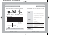
1
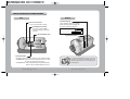
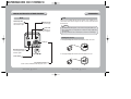
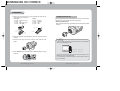
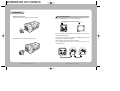
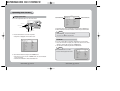
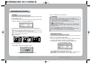
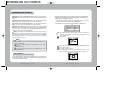
WDR COLOR CCD CAMERA with
DAY & NIGHT
INSTRUCTION MANUAL
SHC-721N/P/PH
About this manual
Before installing and using the camera, please read this manual carefully. Be sure to keep it handy for later reference.
SALES NETWORK
•
SAMSUNG TECHWIN., LTD
Optics & Digital Imaging Division
145-3, Sangdaewon 1-Dong, Jungwon-Gu,
Sungnam, Kyungki-Do, Korea
462-121
TEL : 82-31-740-8137~41
FAX: 82-31-740-8145
www.samsungcctv.com
•
SAMSUNG OPTO-ELECTRONICS AMERICA, INC.
Closed Circuit Division
40 Seaview Drive, Secaucus N.J
07094, U.S.A
TEL : (201) 902-0347
FAX: (201) 902-9342
P/No. : 6806-0393-01A
Printed in Korea
SAMSUNG CCD CAMERA
The lightning flash with an arrowhead symbol, within an equilateral triangle is
intended to alert the user to the presence of uninsulated “dangerous voltage”
within the product's enclosure that may be of sufficient magnitude to
constitute a risk of electric shock to persons.
The exclamation point within an equilateral triangle is intended to alert the user
to the presence of important operating and maintenance (servicing)
instructions in the literature accompanying the appliance.
INFORMATION - This equipment has been tested and found to comply with
limits for a Class A digital device, pursuant to part 15 of the FCC Rules.
These limits are designed to provide reasonable protection against harmful
interference when the equipment is operated in a commercial environment.
This equipment generates, uses, and can radiate radio frequency energy
and, if not installed and used in accordance with the instruction manual, may
cause harmful interference to radio communications.
Operation of this equipment in a residential area is likely to cause harmful
interference in which case the user will be required to correct the interference
at his own expense.
WARNING - Changes or modifications not expressly approved by the
manufacturer could void the user’s authority to operate the equipment.
CAUTION : To prevent electric shock and risk of fire hazards:
Do NOT use power sources other than that specified.
Do NOT expose this appliance to rain or moisture.
This installation should be made by a qualified service person and
should conform to all local codes.
Features
Warning
Wide Dynamic Range(WDR)
Motion Detection
SV-II DSP chip built-in SAMSUNG TECHWIN
allows the camera to find the best picture
conditions in any environment and
automatically gives a necessary light level
compensation, so you can always obtain
the clear picture, the finest detail and
perfect light contrast.
The camera transmits an alert signal to
the REMOTE jack when it detects motion
of an object. If you connect an optional
alarm to the camera, you can get the
effective surveillance.
The camera needs periodic inspection.
Contact an authorized technician for inspection.
Fine Picture Condition Under Very
Low Illumination (Sense up)
VIDEO/DC Lens Selectable
1/3 high density CCD and digital
processor permit high quality pictures to
be captured in very low light condition.
The camera accepts 2 types of auto iris
lenses (DC type/VIDEO type) and is set
with the VIDEO/DC selection switch.
Stop using your camera when you find a malfunction.
If you use your camera around smoke or unusual heat for a long time, a
fire may be caused.
Do not Install the camera on a surface that can not support it.
Unless the surface is suitable, it could cause falling or other hazards.
Do not hold plug with wet hands.
High Resolution
Electronic Iris
The horizontal resolution of 500TV lines
at Color mode and 550TV lines at BW
mode can be achieved by using a high
density CCD having Double Speed
410,000 pixels SONY CCD, which provides
clean, noiseless and reliable pictures.
The electronic iris shutter is automatically
controlled at the speed of
1/60~1/200,000sec (NTSC Models),
1/50~1/200,000sec (PAL Models)
Do not disassemble the camera.
It may result in fire, electric shock or other hazards.
Controlled by OSD menu and
RS-232C
Day & Night
The camera provides automatic mode
changeover by sensing day or night
conditions. It can change color mode in
the day condition for optimal color and
BW mode in night condition for clear
identification.
COLOR CCD CAMERA
It could cause an electric shock.
You can control the camera using OSD
menu and RS-232C jack at a remote
place.
4
User’s Manual
Do not use the camera close to a gas or oil leak.
It may result in fire or other hazards.
COLOR CCD CAMERA
5
User’s Manual
Contents
8
Precautions
Composition
10
Name and Function of Each Part
11
11
12
Front
Side
13
14
Bottom
Back
15
15
Connection
Lens
• Installing Auto Iris Lens
• Installing C/CS-Mount Lens
Connecting to Monitor
19
Connecting to Power
20
COLOR CCD CAMERA
6
User’s Manual
21
Operating Your Camera
21
22
23
26
27
28
32
33
34
35
36
38
40
Configuration of The Menu
Setting Up The Menu
• Camera ID
• Backlight
• White Balance
• Motion Detection
• Lens Selection
• Shutter Speed Control
• Sense up
• Color(Day / Night)
• Synchronization Mode
• Special
Using Remote Jack / MD Output
Troubleshooting
41
Specifications
43
COLOR CCD CAMERA
7
User’s Manual
Precautions
Do not install the camera in
extreme temperature conditions.
Do not install or use the camera in an
environment where the humidity is high.
Only use the camera under conditions
where temperatures are between -10 C
and +50 C. Be especially careful to provide
ventilation when operating under high
temperatures.
It can cause the image quality to be poor.
Do not install the camera under
unstable lighting conditions.
Do not drop the camera or subject
them to physical shocks.
It can cause malfunctions to occur.
Never keep the camera face to
strong light directly.
It can damage the CCD.
Do not expose the camera to rain
or spill beverage on it.
Do not touch the front lens of the
camera.
If it gets wet, wipe it dry immediately.
Liquids can contain minerals that corrode
the electronic components.
Notes
Severe lighting change or flicker can
cause the camera to work improperly.
COLOR CCD CAMERA
8
It is one of the most important parts of
the camera. Be careful not to be stained
by fingerprint.
User’s Manual
• If the camera is exposed to spotlight or object reflecting strong light, smear or
blooming may occur.
• Please check that the power satisfies the normal specification before connecting
the camera.
COLOR CCD CAMERA
9
User’s Manual
Composition
Name and Function of Each Section
Front
1. WDR Color CCD Camera
SHC-721
C-Mount Lens Adapter
Used to attach C-mount lens.
Tripod Mounting Bracket Screw Hole
Used to fix the Tripod mounting
bracket on the top of the camera.
2. Auto Iris Lens Plug
3. Remote Plug
4. L-Wrench
5. C-Mount Adapter
6. Instruction Manual
CS-Mount Lens Adapter
Used to attach CS-mount lens.
COLOR CCD CAMERA
10 User’s Manual
COLOR CCD CAMERA
11 User’s Manual
Name and Function of Each Section
Bottom
Side
Auto Iris Lens Connector
Used to connect Auto Iris Lens plug.
DC/VIDEO Selection Switch
Used to choose DC or VIDEO
according to the type of your Auto
Iris Lens.
Menu Setup Buttons Cover
Menu Setup Buttons
• SET Button: Used to access menu mode. Also used to confirm the setting.
• UP/DOWN Button: Used to choose the desired menu item. It also moves
the cursor up or down in the menu screen.
• LEFT/RIGHT Button: Used to change the parameter of the selected menu item.
It also moves the cursor the left or right in the menu screen.
COLOR CCD CAMERA
12 User’s Manual
Tripod Mounting Hole
Used to install the camera on an optional
tripod. The tripod must be equipped with
the screw specified as shown below.
1/4"-20 UNC (20 THREAD)
L:4.5mm±0.2mm (ISO standard),
or 0.197" (ASA standard)
L
Tripod Mounting Bracket
You can remove and install this bracket on the top of
the camera. You must use the supplied screw or the
equivalent (within 4mm). If not, the bracket may not
be fixed properly.
COLOR CCD CAMERA
13 User’s Manual
Name and Function of Each Section
LENS
Back
Video Output Jack
Used to connect an external
video monitor in jack.
Connection
Remote Jack
Used to connect a remote plug.
The lens is not supplied with this camera. Purchase a lens suitable for your
environment. This camera accepts the auto iris lens and both C-and
CS-mount lens.
Notes
Power LED
The LED turns on
when power is supplied.
If the lens is marked with fingerprints or other marks, the image quality might be poor.
It is recommended to use a high quality lens to improve the image quality under
low illumination.
For using main functions it is recommended to use Auto Iris Lens with DC type.
Installing Auto Iris Lens
1. Peel approximately 8mm from the end of the lens cable outer cover.
AC/DC Type
MD Output Terminal
Used to output motion
detection signal.
High Voltage Type
2. Peel approximately 2mm from the end of the cable inner cover.
Frame Ground
AC / DC Power Terminal
Used to connect an AC 24V or DC 12V power source.
COLOR CCD CAMERA
14 User’s Manual
COLOR CCD CAMERA
15 User’s Manual
Connection
3. Remove the cover from the iris lens plug supplied, and solder the lens
cable to the plug as shown below.
• Video type :
No. 1 Pin --- Red (Power source)
No. 2 Pin --- N.C
No. 3 Pin --- White (Video signal)
No. 4 Pin --- Black (GND)
• DC type :
No. 1 Pin --- Damping No. 2 Pin --- Damping +
No. 3 Pin --- Drive +
No. 4 Pin --- Drive -
Installing C/CS-Mount lens
Before mounting a lens, please check whether it is a C-mount or CS-mount lens.
The back focus is set for the CS-mount lens at the factory.
• Mounting a CS-Mount lens
After removing the protecting cap, attach the lens into the camera by turning
clockwise.
Lens cable
No. 3 Pin
No. 1 Pin
connector
No. 4 Pin
No. 2 Pin
4. Remove the protective cap, and attach the lens to the camera by turning
clockwise.
5. Connect the lens plug to the auto iris connector on the right side of the
camera.
6. Set the DC/VIDEO selection switch to DC or VIDEO according to the type
of the lens.
Notes
Use the lens under the specification as shown. Otherwise the lens can damage the
camera or abnormal fixing may result.
C-mount lens : 10 mm or less
CS-mount lens : 5 mm or less
A heavy lens may disturb the balance with the camera and possibly result in
damage. Don't use a lens heavier than 450g.
It is recommended to set the lens ALC mode to Av mode (Average). Pk mode can
be occurred hunting.
COLOR CCD CAMERA
16 User’s Manual
COLOR CCD CAMERA
17 User’s Manual
Connection
• Mounting a C-Mount lens
Connecting to Monitor
1. Attach the C-Mount lens adapter by turning clockwise.
Connect the VIDEO Out jack to the monitor VIDEO In jack.
Monitor
CCD Camera
• As the connecting method varies with the instruments, refer to the manual
supplied with the instrument.
2. Attach the lens to the camera by turning clockwise.
• If necessary, you can connect the monitor to the REMOTE jack on the back
of your camera. For details, see page 40.
• Only connect the cable when the power is turned off.
• Set the 75W/Hi-Z selection switch as shown below if you have an
intermediate device.
Intermediate
CCD Camera
COLOR CCD CAMERA
18 User’s Manual
COLOR CCD CAMERA
19 User’s Manual
End monitor
Connection
Operating Your Camera
Connecting to Power
Configuration of The Menu
Each model has different power specification. Please check the name of the
model and power specification before connecting to power source.
Setup Menu
Camera ID (see page 23)
• OFF • ON
Backlight (see page 26)
• WDR • BLC • OFF
Connecting method for AC/DC Power Type
Use AC 24V/300mA or DC 12V/500mA power source for SHC-721N/P.
White Bal. (see page 27)
• W-ATW • S-ATW • H-ATW
• AWC
• Manual
• L-ATW
Motion Det. (see page 28)
• OFF • MD1 • MD2
Lens (see page 32)
• DC / Video • Manual
Shutter (see page 33)
• OFF • 1/100 • ESC • Manual
Connecting method for High Voltage Type
Use AC 230V, 50Hz power source for SHC-721PH.
Sense up (see page 34)
• Auto • OFF
Color (see page 35)
• Auto1 • Auto2 • ON • OFF
Sync. (see page 36)
• INT • L/L
Notes
• Be sure to connect power only after all the installation is complete.
• Note that AC or DC adaptor is not supplied with camera.
• Use the UL listed, class 2 power transformer of AC 24V adaptor.
• Ground should be connected to the GND terminal.
COLOR CCD CAMERA
20 User’s Manual
Special (see page 38)
• Gain • DNR • Privacy
• Reset • End • Exit
• Timer
END
COLOR CCD CAMERA
21 User’s Manual
• Demo
Operating Your Camera
Setup
Setting Up The Menu
Use the five Setup Menu buttons on side of the camera.
Select the function using
the UP or DOWN button.
UP button
LEFT button
SET button
RIGHT button
DOWN button
1. Press the SET button to access the setup mode.
Camera ID
Backlight
White Bal.
Motion Det.
Lens
Shutter
Sense up
Color
Sync.
Special
End
Change the status using
the LEFT or RIGHT button.
OFF
WDR
W-ATW
OFF
DC
OFF
OFF
Auto1
INT
3. Change the status of the selected feature using the LEFT or RIGHT button.
4. When completed, move the arrow indicator to 'End' and press the SET button.
Notes
• For the mode with you can access submenu.
• You can access submenu using SET button.
• Setup menu is displayed on the monitor screen.
Setup
Camera ID
Backlight
White Bal.
Motion Det.
Lens
Shutter
Sense up
Color
Sync.
Special
End
Camera ID
OFF
WDR
W-ATW
OFF
DC
OFF
OFF
Auto1
INT
If you enter a camera ID, the name will be displayed in the screen monitor.
1. Press the SET button to display the setup menu and move the arrow
indicator to 'Camera ID' using the UP or DOWN button.
2. Set 'Camera ID' to 'ON' using the LEFT or RIGHT button.
Notes
• If the camera ID feature is set to 'OFF',
the name will not displayed in the monitor.
2. Select the desired feature using the UP or DOWN button.
• Each time you press the UP or DOWN button, the arrow indicator
moves up or down.
• Move the arrow indicator to the desired feature item.
COLOR CCD CAMERA
22 User’s Manual
COLOR CCD CAMERA
Setup
Camera ID
Backlight
White Bal.
Motion Det.
Lens
Shutter
Sense up
Color
Sync.
Special
End
23 User’s Manual
OFF
WDR
W-ATW
OFF
DC
OFF
OFF
Auto1
INT
Operating Your Camera
3. Press SET button.
5. Select the position at which the camera ID will be located on the screen.
Move the cursor to 'Pos' and press SET button.
Camera ID
Camera ID
POS CLR RESET END
POS CLR RESET END
4. You can enter up to 16 characters.
Move the cursor to character-enter location by using the LEFT or
RIGHT button.
Select the desired character by using UP or DOWN button.
•The factory defualt characters are A, B, ···, a, b, ···, ., -, ··· 0, 1···, 8, 9
The camera ID is displayed on the bottom-right of the monitor screen.
(Default position)
Camera ID
FRONT DOOR
POS CLR RESET END
Press the SET button to confirm the blinking character. The first
character is saved and the cursor in the bottom of the screen moves to
the next position.
Repeats steps , and until you create the full name you want.
Select the position by using the 4-directional buttons, then press the SET button to
confirm the position.
FRONT DOOR
Notes
• If you make a mistake while entering name
Move the cursor to ‘Clr’, press ‘SET’ button.
After erasing the character from right to left, correct the character again.
6. When completed, move the cursor to 'End' and press SET button.
COLOR CCD CAMERA
24 User’s Manual
COLOR CCD CAMERA
25 User’s Manual
Operating Your Camera
4. When completed, press the SET button.
Backlight
SV-II DSP chip built-in provides intelligent light level control to overcome the
severe Backlight conditions.
1. Press the SET button to display the setup menu and move the arrow
indicator to ‘Backlight’ using the UP or DOWN button.
Setup
Camera ID
Backlight
White Bal.
Motion Det.
OFF
WDR
W-ATW
OFF
2. SET ‘Backlight’ to the desired mode using the LEFT or RIGHT button.
WDR: In case that bright and dark parts exist on the screen at the same time,
your camera allows you to see both parts clearly
BLC: When the image is in front of strong background lighting, your camera
allows you to get the clear image
OFF: Deactivation
Notes
• If you select ESC or manual in ‘shutter’ menu, you can’t use WDR mode.
• If you select WDR mode, the following phenomenon may appear by lighting
condition. In these cases do not select WDR mode.
Unnatural color change or unnatural phenomenon on the screen
Noise of bright part on the screen
• According to the area of bright part on the screen there may be the difference of
WDR performance so be sure to adjust the degrees of the visual angle when
installing your camera.
• If you increase WDR level, unnatural phenomenon may appear.
• For the optimal WDR performance, in case of observing the object that is in the
place of the changing illumination, use Auto Iris Lens with DC type.
White Balance Control
Your camera provides 6 ‘White Bal.’ control modes. You can select the most
suitable one. You can adjust the white balance.
1. Press the SET button to display the setup menu and move the arrow
indicator to 'White Balance' using the UP or DOWN button.
2. Set ‘White Bal.’ to the desired mode using LEFT or RIGHT button.
WDR
BLC
OFF
3. Press the ‘SET’ button.
• When ‘WDR’ is chosen, you can adjust the level.
WDR Set
Level
OFF
WDR
W-ATW
OFF
DC
0
Press SET to Return
You can select the level from -4 to 4. WDR sensitivity is increased or decreased.
COLOR CCD CAMERA
Setup
Camera ID
Backlight
White Bal.
Motion Det.
Lens
26 User’s Manual
The six white balance control modes are as follows :
W-ATW(Wide Auto Tracking White balance): When color temperature is
2400~12000K, select this mode. (EX. a fluorescent lamp, outdoor)
COLOR CCD CAMERA
27 User’s Manual
Operating Your Camera
S-ATW(Special Auto Tracking White balance): When color temperature is
1800~6000K, specially in sodium lamp, select this mode. (EX. sodium lamp, inside the
tunnel)
H-ATW(High Auto Tracking White balance): If there are bright and dark parts
on the screen at the same time, White Balance operates for bright part.
L-ATW(Low Auto Tracking White balance): If there are bright and dark parts
on the screen at the same time, White Balance operates for dark part.
AWC(Auto White balance Control): The white balance is automatically adjusted
in a specific environment. In order to obtain the best result, press the SET button while
the camera focuses on white paper. If the environment including the light source is
changed, you have to adjust the white balance again.
Manual: To fine adjust, select the Manual mode. You can increase or decrease
the red or blue factor while monitoring the difference on the screen. Set to 'Manual'
mode and press the SET button. Increase or decrease the value for red(R-Gain)
and blue(B-Gain), watching the color of the picture, and press the SET button
when you obtain the best color.
This feature is useful when you have to monitor several screens simultaneously.
Whenever your camera detects motion of object displaying ‘Motion Detected’
with the number counted up on the screen.
1. Press the SET button to display the setup menu and move the arrow
indicator to 'Motion Det.' using the UP or DOWN button.
2. Set ‘Motion Det.’ to the desired mode using LEFT or RIGHT button.
Setup
Camera ID
Backlight
White Bal.
Motion Det.
Lens
Shutter
OFF
WDR
W-ATW
OFF
DC
OFF
MD1: Your camera detects the object’s motion by outline or difference of a
color tone, so this mode is very useful for the daytime or observing
small moving object.
Press SET button.
Notes
• Proper White Balance may not be obtained under the following conditions, in these
cases select the AWC mode.
When the scene contains mostly high color temperature object, such as a blue
sky or sunset.
When the scene is dim.
If your camera faces fluorescent lamp directly or is installed in the place of the
changing illumination.
Move the arrow indicator to ‘Area Set’ using UP and DOWN button, and
then press the SET button.
Set the areas you want to observe.
· You can adjust the top, bottom, left and right base lines by 13 steps
from top to bottom, 18 steps from left to right with an increment of 1.
Motion Detection
Your camera transmits an alert signal when it detects motion of an object on the
screen. If you connect the camera to an external alarm, you can pay attention to
the screen when the alarm sounds.
COLOR CCD CAMERA
28 User’s Manual
COLOR CCD CAMERA
29 User’s Manual
Operating Your Camera
· Move the arrow indicator to 'Top' using the UP or DOWN button and increase
or decrease the value using the LEFT or RIGHT button. Repeat the procedure
for bottom, left and right.
18
· After setting, move the cursor to edge in any direction and then press the button
just one more, let ‘End’ brink.
· Press the SET button.
6
Notes
Tips on Using the Motion Detection Feature
13
Maximum
5
Minimum
• As you increase or decrease MD Level, the areas’ sensitivity is increased or decreased
for object.
• After selecting zone and sensitivity, perform a test operation to make sure it
works properly.
• If the lighting flickers, the motion detection feature might not work properly.
· When completed, press SET button.
Notes
• If you set some areas of 48 areas, your camera detects the object’s motion within
the areas you set.
MD2: Your camera detects object’s motion by the variation of brightness, so
this mode is very useful for night or observing large moving object.
Also MD2 enables you to set seperated areas.
Press SET button.
Move the arrow indicator to ‘Area Set’ like MD1.
Set the areas you want to observe.
• The object should occupy 10% or more of its zone. The bigger the object, the
higher sensitivity.
• If the brightness of an object changes rapidly by sudden lighting change, the
camera may detect it as a motion.
• Your camera can count up to 999. If you reset your camera with selecting ‘Reset’
in Special menu or turn it off and on, your camera’ll count up from 0.
• When this feature is activated, another algorithm may take more time to be operated.
• This system does not guarantee prevention of fires or thefts. The manufacturer
is not responsible for any accident or damage.
• You can use the MD output terminal jack on the rear of the camera to connect
an external alarm device. For details, see page 40.
· Move the cursor to the area you want to observe, and then press the SET
button.
COLOR CCD CAMERA
30 User’s Manual
COLOR CCD CAMERA
31 User’s Manual
Operating Your Camera
Manual: When using manual lens
Lens Selection
• If you select ‘DC’ mode, you can adjust the desired Brightness.
You can set the type of the lens, and control the brightness of the screen.
1. Press the SET button to display the setup menu and move the arrow
indicator to 'Lens' using the UP or DOWN button.
2. Set ‘Lens’ to the desired mode using LEFT or RIGHT button.
• You can select from DC / Video, Manual
Notes
• When the auto iris lens is mounted, you have to set the DC/Video selection
switch on the side of the camera properly according to the type of the lens. The
setup window displays DC or Video according to status of this selection switch.
(refer to page 12 picture)
Setup
Camera ID
Backlight
White Bal.
Motion Det.
Lens
Shutter
Sense up
OFF
WDR
W-ATW
OFF
DC
OFF
OFF
DC / Video: When using auto iris lens
When using Auto Iris Lens with Video type
Adjust ALC volume on the lens properly. Normally ALC volume should be
turned all the way to Av(Average).
According to the type of the lens used, the lens may not perform properly.
In such a case, adjust the volume level on the lens.
For adjusting the volume level set ‘Auto Lens VR Adjust’ level in submenu
. (adjust the level
of the ‘Video’ mode to the middle of bar between
in the place with more than 300lux)
3. When completed move the arrow indicator to ‘END’ and press the SET button.
Shutter Speed Control
You can control brightness of the screen by the shutter speed.
1. Press the SET button to display the setup menu and move the arrow
indicator to ‘Shutter’ using the UP or DOWN button.
2. Set ‘Shutter’ to the desired mode using the LEFT or RIGHT button.
OFF: Deactivation
1/100(1/120: PAL Models): Flickerless mode (When WDR mode is off)
ESC: When setting the optimal shutter speed automatically
Manual: When setting shutter speed manually
Setup
Camera ID
Backlight
White Bal.
Motion Det.
Lens
Shutter
Sense up
Color
OFF
WDR
W-ATW
OFF
DC
OFF
OFF
Auto1
3. If you choose ‘Manual’, select the optimal shutter speed.
COLOR CCD CAMERA
32 User’s Manual
COLOR CCD CAMERA
33 User’s Manual
Operating Your Camera
• You can select speed from ‘1/60’ to ‘1/200,000’sec (NTSC Models), ‘1/50’
to ‘1/200,000’sec (PAL Models).
• When the shutter speed is increased or decreased using the LEFT or RIGHT
button, you can find the difference by monitoring the brightness of the screen.
Manual Set
Manual Set
Value : 1/60
Value : 1/50
Press SET to Return
Press SET to Return
NTSC Models
PAL Models
4. When completed, press the SET button.
Notes
• For effective 1/100 mode set WDR mode in Backlight menu to OFF. 1/100 mode is
not effective with WDR mode.
• If the camera directly faces strong fluorescent light with 'ESC' mode, the image
may become unstable.
• If you choose ‘ESC’, you can adjust the brightness of monitor screen using the
LEFT or RIGHT button.
• If you choose ESC or Manual mode, you can’t use WDR mode in ‘Backlight’ menu.
• If you select manual mode, Sense up is not operated.
Setup
Camera ID
Backlight
White Bal.
Motion Det.
Lens
Shutter
Sense up
Color
OFF
WDR
W-ATW
OFF
DC
OFF
OFF
Auto1
Notes
• If you press the set button on ‘Auto’ mode. You can adjust brightness by increasing or
decreasing the shutter speed. (EX. x2,...., x32, x64, ...., x128)
• If you increase the number of shutter speed, moving object gets an more afterimage.
• Under Sense up activated noise, sports or a whitish phenomenon may appear in the
picture as the sensitivity of the camera is increased. This is normal phenomenon.
Color (Day / Night)
Your camera provides automatic mode changeover by sensing day or night
conditions. It changes to Color mode in day conditions for optimal color and
to BW mode in night conditions for clear identification.
1. Press the SET button to display the setup menu and move the arrow
indicator to ‘Color’ using the UP or DOWN button.
2. Set ‘Color’ to the desired mode using the LEFT or Right button.
Sense up
You can always get the clear image with this function under night or lowlighting level.
1. Press the SET button to display the setup menu and move the arrow
indicator to 'Sense up' using the UP or DOWN button.
2. Set ‘Sense up’ to the desired mode using the LEFT or RIGHT button.
Auto: When your camera is under night or low-lighting level, select this mode.
OFF: Deactivation
COLOR CCD CAMERA
34 User’s Manual
Auto1: When Day & Night function has priority or when you want to decrease the
effect of afterimage with Sense up activated. (color mode
BW mode
BW Sense up mode)
Auto2: When color Sense up mode has priority with Sense up activated.
(color mode
color Sense up mode)
ON: Color mode is kept up.
OFF: A black and white mode is kept up.
COLOR CCD CAMERA
35 User’s Manual
Operating Your Camera
Setup
Camera ID
Backlight
White Bal.
Motion Det.
Lens
Shutter
Sense up
Color
Sync.
OFF
WDR
W-ATW
OFF
DC
OFF
OFF
Auto1
INT
1.Press the SET button to display the setup menu and move the arrow
indicator to ‘Sync.’ using the UP or DOWN button.
2. Set ‘Sync.’ to the desired mode using the LEFT or RIGHT button.
INT: Internal synchronization
L/L: External line-lock synchronization
Setup
Camera ID
Backlight
White Bal.
Motion Det.
Lens
Shutter
Sense up
Color
Sync.
Special
3. Press the SET button.
Notes
• When you use Auto Iris Lens with Video type, do not set the level on the lens to too
low, Color/BW may not change over automatically.
• When Gain in special menu is OFF, Color / BW do not change over automatically.
• If Gain is OFF, color menu displays - - -.
• If Gain is AGC-H or AGC-L from OFF, color menu is back to the mode from - - - that
used to be before Gain was OFF.
• For the stable operation, whenever the mode is changed over between color and BW
mode, five setup menu buttons on the camera do not operate for about 3 seconds.
• The burst signal doesn’t come out with BW mode, so when connecting with
pheripheral equipments be sure to check the specification of those.
• The object may be more out of focus when using a source of near-infrared light
than using the visible light.
OFF
WDR
W-ATW
OFF
DC
OFF
OFF
Auto1
INT
3. If you choose ‘L/L’, you can adjust the desired phase. Press the SET button.
• You can adjust the desired phase from 0 to 270 (factory default: 225).
Line Lock
Phase : 225
Press SET to Return
Notes
Synchronization Mode
Two synchronization modes are available Internal and External line-lock.
In line-lock mode, it synchronizes the video signal between cameras without
a synchronous generator. The line-lock synchronization is only used in the
areas of 60Hz (NTSC Models) / 50Hz (PAL Models).
COLOR CCD CAMERA
36 User’s Manual
• When the power frequency is 50Hz, you can not use line-lock mode(NTSC Models).
• When the power frequency is 60Hz, you can not use the line-lock mode(PAL Models).
• ‘Sync.’ mode is fixed to ‘INT’ in DC 12V input power.
COLOR CCD CAMERA
37 User’s Manual
Operating Your Camera
• Move the arrow indicator to area you want to mask.
• Set ‘On’ using LEFT or RIGHT button.
• Press the SET button and then set the area’s bounds with the method like MD1
Set. (see page 29)
• When completed, press the SET button.
Special
Timer: To see the set time. Before you use Timer you need to set the time up.
(24 hour)
- OFF: the time not displayed on the screen
- ON: the time displayed on the screen
1.Press the SET button to display the setup menu and move the arrow
indicator to ‘Special’ using the UP or DOWN button.
2. Press the SET button.
Gain: To get brighter picture
- AGC-H: Gain is increased or decreased from 0 to 24dB automatically
as following the illumination.
- AGC-L: Gain is increased or decreased from 0 to 19dB automatically
as following the illumination.
- OFF: Deactivation
DNR(Digital Noise Reduction): To reduce the noise on the screen with
Gain
- Low: low reduction of the noise
- High: high reduction of the noise
Privacy: To mask area which you want to mask
- OFF: Deactivation
- ON: Privacy mode activated
• Press the SET button.
COLOR CCD CAMERA
38 User’s Manual
Demo: To see your camera’s main functions
Reset: To reset your camera to factory default condition
End: To move Top-menu
Exit: To finish setting menu
Notes
• The set time in Timer menu is reset automatically after the power is off.
• If you change the ‘Gain’ menu from AGC-L to AGC-H, sensitivity is increased as well
as noise on the screen.
• Afterimage may appear with DNR.
• After Demo operated please reset your camera using ‘Reset’ menu. And then use
your camera with the desired each mode in each menu.
COLOR CCD CAMERA
39 User’s Manual
Using Remote Jack / MD Output
Troubleshooting
If you connect a remote plug to the REMOTE jack on the rear of the camera
as shown below, you can access the menu setup mode from a remote place.
If you have trouble operating your camera, refer to the following table. If the
guidelines do not enable you to solve the problem, contact an authorized
technician.
Problem
1. RS-232C Communication Setting.
• Mode : Serial • Data Bit : 8 • Bit/sec : 19200bps
• Port : Com1
• Parity : None
Solution
Nothing appears on
the screen.
• Check that the power cord and line connection
between the camera and monitor are fixed properly.
• Check that you have properly connected VIDEO
cable to the camera VIDEO output jack.
• Check that the DC/VIDEO selection switch on the
side of the camera is set to a proper position
according to the type of your auto iris lens.
• Are you using Auto Iris Lens with VIDEO type?
Adjust VR Level properly (refer to page 32)
The image on the
screen is dim.
• Is lens stained with dirt? Clean your lens with soft,
clean cloth.
• Set the monitor to proper condition.
• If the camera is exposed to too strong light, change
the camera position.
• Adjust the lens’ focus properly.
The image on the
screen is dark.
• Adjust the contrast feature of the monitor.
• If you have an intermediate device, set the 75Ω / Hi-z
properly. (refer to page 19)
• Are you using the Auto Iris Lens? Adjust the level
on the lens properly.
The camera is not working
properly, and the surface
of the camera is hot.
• Check that you have properly connected the camera
to an appropriate power source. (refer to page 20)
• Stop Bit : 1
2. Setup menu Command.
Setup menu
Set
Up
Down
Left
Right
Command
AA, EE, 0F, CC, 55
AA, EE, 1E, CC, 55
AA, EE, 1D, CC, 55
AA, EE, 1B, CC, 55
AA, EE, 17, CC, 55
Byte
5
5
5
5
5
3. MD(Motion Detection) output Signal Level
+4.0V~+5.0V
There is motion
0V
There is no motion
2.5±0.5sec
Notes
• You must turn the camera power off when you connect or remove the remote plug.
COLOR CCD CAMERA
40 User’s Manual
COLOR CCD CAMERA
41 User’s Manual
Troubleshooting
Specifications
Item
Solution
Problem
Motion Detection
function is not active.
• Have you set ‘Motion Det.’ menu to OFF?
• Have you set ‘MD Level’ to too low?
• Have you set ‘MD Area’ properly?
The color of the picture
is not matched.
• Check that you have properly set the ‘White Bal.’
menu.
The image on the screen
flickers.
• Is the camera facing to direct sunlight or fluoresent
lighting? Change the camera position.
• Are you using Auto Iris Lens? Check that you have
properly connected the lens plug to the Auto Iris
connector on the side of the camera.
SHC-721N
SHC-721P
Power Source
DC 12V / AC 24V compatible
Power Consumption
280mA (DC) / 3.8 W (AC)
Image Sensor
• Have you connected your camera to DC power
source? Connect it to AC power source.
811(H) x 508(V), 1/3" CCD
Effective Pixels
768(H) x 494(V), 1/3" CCD
752(H) x 582(V), 1/3" CCD
2:1 Interlaced 525 Lines/60 Fields/30 Frames
2:1 Interlaced 625 Lines/50 Fields/25 Frames
Scanning System
Video Output
Resolution
Internal / Line Lock
1.0V[p-p] NTSC Composite, 75Ω / BNC Connector
Day & Night
Built-in (46dB)
ON / OFF / AUTO 1 / AUTO 2 (Filter Auto Change)
AGC-L, AGC-H, OFF Selectable
Gain Control
Electronic Shutter Speed
1/60~1/200,000sec (Auto / Manual)
ESC / Video Drive / DC Drive
W-ATW / S-ATW / H-ATW / L-ATW / AWC / Manual
Color: 0.8lux at F1.2, B/W: 0.01lux at F1.2
50dB (AGC Off)
S/N (Y signal)
Built-in
RS-232C
Motion Detection
1/50~1/200,000sec (Auto / Manual)
Built-in (selectable limit~X128)
Sense up
Min. Illumination
1.0V[p-p] PAL Composite, 75Ω / BNC Connector
500Lines (color) / 550Lines (B/W)
Wide Dynamic Range
White Balance
MD1 / MD2 / OFF (Built-in Alarm Output Connector)
O.S.D
Built-in
DNR
Low / High selectable
Privacy Function
ON / OFF (4 Programmable Zone)
Timer
Built-in (24Hour, Not Memoring)
C / CS Mount
Lens Mount
-10°C ~ +50°C (14°F ~ 122°F)
Operating Temperature
30% ~ 90% RH
Operating Humidity
Dimension (mm)
69(W) X 56(H) X 125(D) without mounting foot & connector
460g
Weight (W/O Lens & Power Cord)
42 User’s Manual
795(H) x 596(V), 1/3" CCD
Total Pixels
Iris Mode
COLOR CCD CAMERA
3.8W
1/3", Vertical double density interline CCD
Synchronization
L/L mode isn’t able to
be selected.
SHC-721PH
AC 230V / 50Hz
COLOR CCD CAMERA
43 User’s Manual
500g
DECLARATION OF CONFORMITY
MEMO
Application of Council Directive(s)
89 / 336 / EEC
Manufacturer's Name
SAMSUNG TECHWIN CO., LTD
Manufacturer's Address
SAMSUNG TECHWIN CO., LTD
42, SUNGJU-DONG CHANGWON-CITY,
KYUNGNAM, KOREA, 641-120
European Representative Name
European Representative Address
Equipment Type/Environment
CCTV Camera
Model Name
SHC-721P/PH
Beginning Serial NO.
S2110001
Year of Manufacture
2002. 11. 1
Conformance to
EN 50081-1 : 1992
EMC-Directive 89/336 EEC and 92/31/EEC
EN 50130-4 : 1996
We, the undersigned, hereby declare that the equipment specified above conforms
to the above Directive(s).
SAMSUNG TECHWIN CO., LTD
Legal Representative in Europe
Full Name
YOUNG TAEK SON
Full Name
Position
QUALITY CONTROL MANAGER
Position
Place
CHANGWON, KOREA
Place
Date
2002. 11. 1
Date
Manufacturer
Signature
Signature
MEMO
MEMO