1
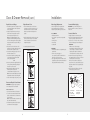
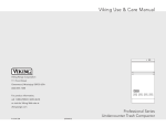
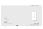
Viking Installation Guide
Viking Range Corporation
111 Front Street
Greenwood, Mississippi 38930 USA
(662) 455-1200
For product information,
call 1-888-VIKING1 (845-4641)
or visit the Viking Web site at
vikingrange.com
UL
F20712C EN
W10345055
C
UL
(093010)
Freestanding French Door
Bottom-Mount Refrigerator/Freezer
with Dispenser
Table of Contents
Warnings & Important Information____________________________________________________________3
Professional
Dimensions (36” Bottom-Mount & French Door Bottom-Mount) __________________________6
Specifications (36” Bottom-Mount & French Door Bottom-Mount) ________________________7
Designer
Dimensions (36” French Door Bottom-Mount) ____________________________________________8
Specifications (36” French Door Bottom-Mount) __________________________________________9
Proper Disposal _____________________________________________________________________________10
Important Safety Instructions ________________________________________________________________11
General Information_________________________________________________________________________12
Remove the Packaging __________________________________________________________________12
Location Requirements __________________________________________________________________12
Moving Refrigerator_____________________________________________________________________13
Electrical Requirements _________________________________________________________________13
Water Supply Requirements _____________________________________________________________14
Door & Drawer Removal
Remove and Replace Handles___________________________________________________________15
Remove Doors and Hinge _______________________________________________________________15
Replace Doors and Hinge _______________________________________________________________16
Remove and Replace Freezer Drawer____________________________________________________16
Replace Drawer Front ___________________________________________________________________16
Installation
Water Supply Requirements _____________________________________________________________17
Connect the Water Supply ______________________________________________________________17
Connect the Water Line _________________________________________________________________17
Leveling ________________________________________________________________________________19
Door Alignment_________________________________________________________________________20
Complete Installation ___________________________________________________________________20
Performance Checklist ______________________________________________________________________21
Service & Registration _______________________________________________________________________22
2
IMPORTANT– Please Read and Follow
It is the customer’s responsibility to:
• Contact a qualified electrical installer.
• Read all instructions before using the
refrigerator.
• Observe all local codes and ordinances.
Install refrigerator according to installation
instructions. All connections for water,
electrical power and grounding must
comply with local codes and be made by
licensed personnel when required.
• DO NOT modify plug on power cord. If
plug does not fit electrical outlet, have
proper outlet installed by a qualified
technician. Replace worn power cords
and/or loose plugs.
• Assure that the electrical installation is
adequate and in conformance with the
National Electrical Code, ANSI/NFPA
70-latest edition or Canadian Electrical
Code C22.1-1998 and C22.2 No. 0-M91
(or latest edition), and all local codes and
ordinances. (115 volt, 60-Hz, 15 amp,
fused, electrical supply is required. It is
required that a separate circuit serving only
this appliance be provided. This appliance
is equipped with a power supply cord
having a 3-prong grounding plug. To
minimize possible shock hazard, the cord
must be plugged into a mating 3-prong,
grounding type wall receptacle. If a
2-prong receptacle is encountered, the
customer must contact a qualified
electrical installer to have it replaced with a
properly grounded 3-prong receptacle.
DO NOT use an extension cord or adapter
plug.
• DO NOT ground to a gas line or coldwater pipe.
• DO NOT remove warning tag from power
cord.
• Refrigerator is designed to operate on a
separate 115 volt, 15 amp., 60 cycle line.
• DO NOT tamper with refrigerator controls.
• DO NOT service or replace any part of
refrigerator unless specifically
recommended in Use & Care or Installation
Instructions. DO NOT attempt service if
instructions are not understood or if they
are beyond personal skill level.
• Always disconnect refrigerator from
electrical supply before attempting to
change light bulbs, clean, or service the
refrigerator. Disconnect the power cord by
grasping the plug, not the cord.
• Always read and follow manufacturer’s
storage and ideal environment instructions
for items being stored in refrigerator.
• DO NOT allow children to operate, play
with, crawl inside or stand on any part of
the refrigerator.
• DO NOT clean refrigerator parts with
flammable fluids. The fumes can create a
fire hazard or explosion.
• Clean up spills or water leakage associated
with water installation.
• Keep your refrigerator in good condition.
Bumping or dropping refrigerator can
damage refrigerator or cause refrigerator
to malfunction or leak. If damage occurs,
have refrigerator checked by qualified
service technician.
3
Refrigerator Safety
IMPORTANT– Please Read and Follow
A GFI shall be used if required by NFPA70 (National Electric Code),
federal/state/local laws, or local
ordinances.
• The required use of a GFI is normally
related to the location of a receptacle with
respect to any significant sources of water
or moisture.
• Viking Range Corporation will NOT
warranty any problems resulting from GFI
outlets which are not installed properly or
do not meet the requirements below.
If the use of a GFI is required, it should be:
• Of the receptacle type (breaker type or
portable type NOT recommended)
• Used with permanent wiring only
(temporary or portable wiring NOT
recommended)
• On a dedicated circuit (no other
receptacles, switches or loads in the
circuit)
• Connected to a standard breaker of
appropriate size (GFI breaker of the same
size NOT recommended)
• Rated for Class A (5 mA +/- 1 mA trip
current) as per UL 943 standard)
• In good condition and free from any
loose-fitting gaskets (if applicable in
outdoor situations)
• Sheltered from moisture (water, steam,
high humidity) as much as reasonably
possible
4
5
Dimensions
Specifications
(Professional)
36” Professional French Door
35
w/
sid (91-7/8
e p .1 ”
an cm
els )
ac
ce
(Professional)
Professional French Door Bottom-Mount
Description
VCFF136D
Overall width
35-5/8” (90.5 cm)
Addition of side panels: 35-7/8” (91.1 cm)
Overall height
To top of door: 69-7/8” (177.5 cm) min. to 70-5/8” (179.4 cm) max.
To top of hinge cap: 69-5/8” (176.8 cm) min. to 70-3/8” (178.8 cm) max.
To top of cabinet: 68-3/8” (173.7 cm) min. to 69-1/8” (175.6 cm) max.
Addition of top grilles: 71-7/8” (182.6 cm) min. to 72-5/8” (184.5 cm) max.
sso
ry
Overall depth from rear
To front edge of cabinet:
To front of door:
To front of handle endcap:
Cutout height
70-1/4” (178.4 cm)
Addition of top grilles:
44
(11-3/1
2.2 6”
cm
)
71
(18 -7/8
2.6 ”
mi cm)
n.
t
72 o
(18 -5/8
4.5 ”
ma cm)
x.
24
(62-3/4
.9 ”
cm
)
Cutout width
36” (91.4 cm)
Cutout depth
24” (61.0 cm)
Electrical requirements
Maximum amp usage
Inlet water requirements
35
(90-5/8
.5 ”
cm
)
1/4” copper tubing inlet waterline; minimum 35 psi; maximum 120 psi
Overall interior capacities
Refrigerator
Freezer
Total capacity
Approximate shipping weight
14.8 cu. ft. (419 liters)
5.0 cu. ft. (142 liters)
19.8 cu. ft. (560 liters)
321 lbs. (145.6 kg)
.4
2”
-1/cm)
3
2
(59
.7
8”
- 1/ )
26.4 cm
(66
6
72” (182.9 cm)
115 volt, 60 Hz, 15 amp dedicated circuit; 3-wire cord with
grounded 3-prong plug attached to product
10 amps
8”
-1/cm)
8
2
(71
23-1/2” (59.7 cm)
26-1/8” (66.3 cm)
28-1/8” (71.4 cm)
7
Dimensions
Specifications
(Designer)
36” Designer French Door
35
w/
sid (91-7/8
e p .1 ”
an cm
els )
ac
ce
(Designer)
Designer French Door Bottom-Mount
Description
DDFF136D
Overall width
35-5/8” (90.5 cm)
Addition of side panels: 35-7/8” (91.1 cm)
Overall height
To top of door: 69-7/8” (177.5 cm) min. to 70-5/8” (179.4 cm) max.
To top of hinge cap: 69-5/8” (176.8 cm) min. to 70-3/8” (178.8 cm) max.
To top of cabinet: 68-3/8” (173.7 cm) min. to 69-1/8” (175.6 cm) max.
Addition of top grilles: 71-7/8” (182.6 cm) min. to 72-5/8” (184.5 cm) max.
sso
ry
Overall depth from rear
To front edge of cabinet:
To front of door:
To front of handle endcap:
Cutout height
70-1/4” (178.4 cm)
Addition of top grilles:
44
(11-3/1
2.2 6”
cm
)
71
(18 -7/8
2.6 ”
mi cm)
n.
t
72 o
(18 -5/8
4.5 ”
ma cm)
x.
24
(62-3/4
.9 ”
cm
)
Cutout width
36” (91.4 cm)
Cutout depth
24” (61.0 cm)
Electrical requirements
Maximum amp usage
Inlet water requirements
35
(90-5/8
.5 ”
cm
)
1/4” copper tubing inlet waterline; minimum 35 psi; maximum 120 psi
Overall interior capacities
Refrigerator
Freezer
Total capacity
Approximate shipping weight
14.8 cu. ft. (419 liters)
5.0 cu. ft. (142 liters)
19.8 cu. ft. (560 liters)
321 lbs. (145.6 kg)
.4
2”
-1/cm)
3
2
(59
.7
8”
- 1/ )
26.4 cm
(66
8
72” (182.9 cm)
115 volt, 60 Hz, 15 amp dedicated circuit; 3-wire cord with
grounded 3-prong plug attached to product
10 amps
8”
-1/cm)
8
2
(71
23-1/2” (59.7 cm)
26-1/8” (66.3 cm)
28-1/8” (71.4 cm)
9
Proper Disposal (of old refrigerator)
Important Safety Instructions
IMPORTANT:
Child entrapment and suffocation are not
problems of the past. Junked or abandoned
refrigerators are still dangerous - even if they will
sit for “just a few days.” If you are getting rid of
your old refrigerator, please follow these
instructions to help avoid accidents.
Before You Throw Away Your Old Refrigerator
or Freezer:
• Take off the doors.
• Leave the shelves in place so that children may
not easily climb inside.
10
11
General Information
General Information
Clean Before Using
Your refrigerator was packed carefully for
shipment. Remove and discard all packaging and
tape. DO NOT remove the model/serial number
label.
After you remove all of the packaging materials,
clean the inside of your refrigerator before using
it. See the cleaning instructions in “Use and
Care Guide.”
Important information to know about glass
shelves and covers:
DO NOT clean glass shelves or covers with warm
water when they are cold. Shelves and covers
may break if exposed to sudden temperature
changes or impact, such as bumping. For your
protection, tempered glass is designed to shatter
into many small, pebble-size pieces. This is
normal. Glass shelves and covers are heavy. Use
special care when removing them to avoid impact
from dropping.
Remove the Packaging
• Remove tape and glue residue from surfaces
before turning on the refrigerator. Rub a small
amount of liquid dish soap over the adhesive
with your fingers. Wipe with warm water and
dry.
• DO NOT use sharp instruments, rubbing
alcohol, flammable fluids, or abrasive cleaners
to remove tape or glue. These products can
damage the surface of your refrigerator. For
more information, see “Refrigerator Safety.”
• Dispose of/recycle all packaging materials.
Electrical Requirements
To ensure proper ventilation for your refrigerator,
allow for a 1/2" (1.25 cm) space on each side and
at the top. Allow 1" (2.5 cm) of space behind the
refrigerator. If your refrigerator has an ice maker,
allow extra space at the back for the water line
connections. When installing your refrigerator next
to a fixed wall, leave a 2-3/4" (7.0 cm) minimum
space between the refrigerator and wall to allow
the door to swing open.
Overhead View
Wall
1/2”
(1.27 cm)
2-3/4”
Wall
(6.99 cm)
Before you move your refrigerator to its final
location, it is important to make sure you have
the proper electrical connection.
Door
Recommended Grounding Method
A 115 Volt, 60 Hz., AC only 15- or 20-amp fused,
grounded electrical supply is required. It is
recommended that a separate circuit serving only
your refrigerator be provided. Use an outlet that
cannot be turned off by a switch. DO NOT use an
extension cord.
Moving Unit
When moving your refrigerator:
Your refrigerator is heavy. When moving the
refrigerator for cleaning or service, be sure to
protect the floor. Always pull the refrigerator
straight out when moving it. Do Not wiggle or
“walk” the refrigerator when trying to move, as
floor damage could occur.
Location Requirements
• DO NOT install refrigerator near oven, radiator
or other heat sources. If not possible, shield
refrigerator material.
• DO NOT install where the temperature falls
below 55°F (13°C) or rises above 110°F (43°C).
Malfunctions can occur at these temperatures.
• Refrigerator is designed for indoor household
application only.
12
• DO NOT transport the refrigerator on its side. If
an upright position is not possible, lay the
refrigerator on its back. Allow refrigerator to sit
upright for approximately 30 minutes before
plugging it in to assure oil returns to the
compressor. Plugging the refrigerator in
immediately may cause damage to internal
parts.
• Use an appliance dolly when moving
refrigerator. ALWAYS truck refrigerator from its
side or back - NOT from its front.
• Cover outside finish of refrigerator during
transport by wrapping cabinet in blankets
or inserting padding between the refrigerator
and dolly.
• Secure refrigerator to dolly firmly with straps or
bungee cords. Thread straps through handles
when possible. DO NOT overtighten.
Overtightening restraints may dent or damage
outside finish.
NOTE: Before performing any type of installation,
cleaning, or removing a light bulb, turn the
cooling OFF. Disconnect the refrigerator from the
electrical source. When you are finished,
reconnect the refrigerator to the electrical source
and turn cooling on.
13
General Information
Doors & Drawer Removal
Water Supply Requirements
Remove and Replace Handles
A cold water supply with water pressure of
between 35 and 120 psi (241 and 827 kPa) is
required to operate the water dispenser and ice
maker. If you have questions about your water
pressure, call a licensed, qualified plumber.
Reverse Osmosis Water Supply (cont.)
• If your refrigerator has a water filter, it may
further reduce the water pressure when used in
conjunction with a reverse osmosis system.
Remove the water filter.
Reverse Osmosis Water Supply
IMPORTANT: The pressure of the water supply
coming out of a reverse osmosis system going to
the water inlet valve of the refrigerator needs to
be between 35 and 120 psi (241 and 827 kPa).
If you have questions about your water pressure,
call a licensed, qualified plumber.
Remove Doors and Hinges (cont.)
6. Disconnect the water line by holding the tabbed
section of the water line while turning the black
locking collar clockwise. See Connections graphic.
OR
6a.Disconnect the water line by pulling back on the
locking collar while pulling the water line out of
the water line connector. See Connections
graphic.
7. Remove the parts for the top hinge as shown in
Top Hinge graphic. Lift the left-hand side door
from the bottom hinge pin.
NOTE: On some models, remove the shim from
the bottom hinge pin and keep it for later use.
See Bottom Hinge graphic.
8. Using a 3/8" hex wrench, remove the leveling leg
brackets from the bottom of the cabinet. Keep
screws for later use.
1. Using a 3/32"or 1/8” hex wrench, loosen the
two set screws located on the side of each
handle.
2. Pull the handle straight out from the door.
Make sure you keep the screws for reattaching
the handles.
3. To replace the handles, reverse the directions.
Remove Doors and Hinges
IMPORTANT:
• Remove food and any adjustable door or utility
bins from doors.
• Keep the refrigerator doors closed until you are
ready to lift them free from the cabinet.
NOTE: Provide additional support for the
refrigerator door while the hinges are being
removed. DO NOT depend on the door gasket
magnets to hold the door in place while you are
working.
If a reverse osmosis water filtration system is
connected to your cold water supply, the water
pressure to the reverse osmosis system needs to
be a minimum of 40 to 60 psi (276 to 414 kPa).
If the water pressure to the reverse osmosis
system is less than 40 to 60 psi (276 to 414 kPa):
Top Hinges
A
B
• Check to see whether the sediment filter in the
reverse osmosis system is blocked. Replace the
filter if necessary.
TOOLS NEEDED: 5/16", 3/8", 1/4" hex-head
socket wrench, #2 Phillips screwdriver, and a flatblade screwdriver.
• Allow the storage tank on the reverse osmosis
system to refill after heavy usage.
1. Unplug refrigerator or disconnect power.
2. Remove the base grille. Grasp the grille firmly
and pull it toward you.
C
D
A. Hinge Cover Screw
B. Top Hinge Cover
C. 5/16" Hex-Head Hinge Screws
D. Top Hinge
Bottom Hinges
A
B
C
3. Starting with the right-hand side door, remove
the parts for the top hinge as shown in Top
Hinge graphic. Lift the refrigerator door from
the bottom hinge pin.
4. Remove the shim from the bottom hinge pin
and keep it for later use. See Bottom Hinge
graphic.
5. Remove top hinge cover from left side
refrigerator door. Disconnect the wiring plug
located on top of the hinge by wedging a flatblade screwdriver or your fingernail between
the two sections. See Connections graphic.
.
14
A. Shim (on some models)
B. Bottom Hinge
C. Hinge Screws
6
6a
Connections
Connections
A
B
B
A
OR
A. Tabs
B. Wiring Plug
15
A. Wiring Plug
B. Water Line Connection
Door & Drawer Removal (cont.)
Installation
Replace Doors and Hinges
Replace Drawer Front
Water Supply Requirements
Connect the Water Supply
1. Assemble the parts for the top hinge as shown
in Top Hinge graphic. DO NOT tighten the
screws completely.
2. Replace the parts for the bottom hinge as
shown in Bottom Hinge graphic. Tighten
screws. Replace the refrigerator door.
Note: Provide additional support for the
refrigerator door while the hinges are being
moved. DO NOT depend on the door gasket
magnets to hold the door in place while you
are working.
3. Align the door so that the bottom of the
refrigerator door aligns evenly with the top of
the freezer drawer. Tighten all screws.
4. Reconnect the wiring plug on top of the lefthand side refrigerator door.
5. Reconnect the water lines by firmly pushing
one line inside the other. Slide the black
locking collar fully forward.
OR
5a.Reconnect the water line by pulling back the
locking collar ring while firmly pushing the
water line into the connector.
6. While holding the tabbed section of the
waterline, turn the locking collar
counterclockwise until you hear a “click.”
Note: The arrow on the tabbed section should
align with the two bars on the locking collar.
7. Check for leaks. Replace the top hinge covers.
1. Slide the drawer glides out of the freezer
compartment. Insert the screws in the top of
the drawer front into the slots in the drawer
brackets. See Drawer Front Replacement
graphic.
Gather the required tools and parts before
starting installation. Read and follow the
instructions provided with any tools listed here.
IMPORTANT: If you turn the refrigerator on
before the water line is connected, turn the ice
maker OFF.
TOOLS NEEDED:
• Flat-blade screwdriver
• 7/16" and 1/2" Open-end or two adjustable
wrenches
• 1/4" Nut driver
• 1/4" Drill bit
• Cordless drill
Connect to Water Line
2. Pull the drawer brackets toward you to position
the two screws in the bottom of the drawer
front into the brackets. See Drawer Front
Replacement graphic.
1. Unplug refrigerator or disconnect power.
2. Turn OFF main water supply. Turn ON nearest
faucet long enough to clear line of water.
3. Locate a 1/2" to 1-1/4" (12.7 mm to 31.8 mm)
vertical cold water pipe near the refrigerator.
IMPORTANT:
• Make sure it is a cold water pipe.
• Horizontal pipe will work, but drill on the top
side of the pipe, not the bottom. This will
help keep water away from the drill and
normal sediment from collecting in the valve.
4. Determine the length of copper tubing you
need. Measure from the connection on the rear
of the refrigerator to the water pipe.
Add 7 ft (2.1 m) to allow for cleaning. Use
1/4" (6.35 mm) O.D. (outside diameter) copper
tubing. Be sure both ends of copper tubing are
cut square.
5. Using a cordless drill, drill a 1/4" hole in the
cold water pipe you have selected.
3. Completely tighten the four screws.
Drawer Front Removal
A
A. Loosen 4 Door Bracket Screws
IMPORTANT:
• All installations must meet local plumbing code
requirements.
• DO NOT use a piercing-type or
3/16" (4.76 mm) saddle valve which reduces
water flow and clogs more easily.
• Use copper tubing and check for leaks. Install
copper tubing only in areas where the household
temperatures will remain above freezing.
A
B
C
Drawer Front Replacement
D
E
F
G
Remove and Replace Freezer Drawer
IMPORTANT: Two people may be required to
remove and replace the freezer drawer.
Remove Drawer Front
1. Open the freezer drawer to full extension.
2. Loosen the four screws attaching the drawer
glides to the drawer front. See Drawer Front
Removal graphic.
Note: Loosen screws three to four turns. Keep
the screws in the drawer front.
3. Lift drawer front upward and off the screws.
See Drawer Front Removal graphic.
A. Cold water pipe
B. Pipe clamp
C. Copper tubing
D. Compression nut
16
17
E. Compression sleeve
F. Shutoff valve
G. Packing nut
Installation
Leveling
Connect to Water Line (cont.)
5. Using an adjustable wrench, hold the nut on
the plastic water line to keep it from moving.
Then, with a second wrench, turn the
compression nut on the copper tubing
counterclockwise to completely tighten. Do not
overtighten.
6. Fasten the shutoff valve to the cold water pipe
with the pipe clamp. Be sure the outlet end is
solidly in the 1/4" drilled hole in the water pipe
and that the washer is under the pipe clamp.
Tighten the packing nut. Tighten the pipe
clamp screws slowly and evenly so washer
makes a watertight seal. DO NOT overtighten
or you may crush the copper tubing.
7. Slip the compression sleeve and compression
nut on the copper tubing as shown. Insert the
end of the tubing into the outlet end squarely
as far as it will go. Screw compression nut onto
outlet end with adjustable wrench. DO NOT
overtighten.
8. Place the free end of the tubing in a container
or sink, and turn ON the main water supply.
Flush the tubing until water is clear. Turn OFF
the shutoff valve on the water pipe. Coil the
copper tubing.
To enhance the appearance and maintain performance, the refrigerator should be level.
To protect property and refrigerator from damage, observe the following:
• Protect vinyl or other flooring with cardboard, rugs, or other protective material.
• DO NOT use power tools when performing leveling procedure.
Materials Needed
• 1/4” hex head driver
• Carpenter’s level
A
B
Note: Complete any required panel installation and/or water supply connection before leveling.
Refrigerator should be in permanent location prior to leveling.
C
D
A. “P” clamp
B. Plastic water line
1
2
C. Compression nut
D. Copper tubing
6. Check connection by pulling on copper tubing.
Attach copper tubing to refrigerator cabinet
with a “P” clamp. Turn on water supply to
refrigerator and check for leaks. Correct any
leaks.
Connect to Refrigerator
1. Create a service loop (minimum diameter of 2
ft. [61.0 cm]) with the copper tubing. Avoid
kinks when coiling the copper tubing.
2. Remove the plastic cap from water valve inlet
port. Place a compression nut and sleeve on
the copper tubing.
3. Insert the end of the copper tubing into the
water valve inlet port. Shape tubing slightly so
that the tubing feeds straight into the port to
avoid kinks.
4. Slide the compression nut over the sleeve and
screw into the water valve inlet port.
To raise the front of the refrigerator, turn the leveler foot
screw clockwise. Note: Having someone push against the
top of the refrigerator takes some weight off the leveler
foot screws.
Remove toe grille. Grasp firmly and pull outward
to unclip.
3
4
A
B
C
D
A. Plastic water tubing
B. Sleeve
C. Compression nut
D. Copper tubing
Replace toe grill. Align the toe grille mounting clips
with the lower cabinet slots. Push the toe grille firmly
until it snaps into place. Check for level.
To lower the front of the refrigerator, turn the leveler foot
screw counterclockwise. Note: It may take several turns
of the leveler foot screw to adjust the tilt of the
refrigerator.
18
19
Door Alignment
(French Door Bottom-Mount)
Performance Checklist
2
1
To raise left side door, turn leveler foot
screw clockwise.
Remove toe grille. Grasp firmly and pull outward to
unclip.
3
4
Replace toe grill. Align the toe grille mounting clips
with the lower cabinet slots. Push the toe grille firmly
until it snaps into place.
To raise left side door, turn leveler foot
screw clockwise.
h Plug-in refrigerator and verify operation.
Installer’s information:
h Connect water supply (if applicable).
• Verify icemaker bail arm is down.
• Verify dispenser operation
(if applicable).
h Align/square door(s).
Installer’s name:_____________________________
Installer’s company:__________________________
Date:_______________________________________
h Verify drain pan properly installed and no leaks
on water connection.
h Remove internal packaging and labels and
wipe refrigerator down.
Complete the Installation
Final Steps
1. Plug into a grounded 3 prong outlet.
2. Return all removable parts to doors and drawer
and food to refrigerator and freezer.
Note: Allow 24 hours to produce the first batch
of ice. Discard the first three batches of ice
produced. Allow three days to completely fill the
ice container.
20
21
Service & Registration
Notes
Only authorized replacement parts may be used in performing service on the appliance.
All servicing should be referred to a qualified technician.
________________________________________________________________________________________________________________________________________________________
________________________________________________________________________________________________________________________________________________________
Contact Viking Range Corporation, 1-888-VIKING1 (845-4641), for the nearest service parts
distributor in your area or write to:
VIKING RANGE CORPORATION
PREFERRED SERVICE
1803 Hwy 82W
Greenwood, Mississippi 38930 USA
The serial and model numbers for your refrigerator are located on the upper wall, behind the lighting.
________________________________________________________________________________________________________________________________________________________
________________________________________________________________________________________________________________________________________________________
________________________________________________________________________________________________________________________________________________________
________________________________________________________________________________________________________________________________________________________
________________________________________________________________________________________________________________________________________________________
Record the following information indicated below. You will need it if service is ever required.
________________________________________________________________________________________________________________________________________________________
Model number ____________________________________________________________________________________
________________________________________________________________________________________________________________________________________________________
Serial number _____________________________________________________________________________________
Date of purchase __________________________________________________________________________________
Date installed ______________________________________________________________________________________
________________________________________________________________________________________________________________________________________________________
________________________________________________________________________________________________________________________________________________________
________________________________________________________________________________________________________________________________________________________
________________________________________________________________________________________________________________________________________________________
Dealer's name _____________________________________________________________________________________
________________________________________________________________________________________________________________________________________________________
Address ___________________________________________________________________________________________
________________________________________________________________________________________________________________________________________________________
These installation instructions should remain with the refrigerator for future
reference.
________________________________________________________________________________________________________________________________________________________
________________________________________________________________________________________________________________________________________________________
________________________________________________________________________________________________________________________________________________________
________________________________________________________________________________________________________________________________________________________
________________________________________________________________________________________________________________________________________________________
________________________________________________________________________________________________________________________________________________________
________________________________________________________________________________________________________________________________________________________
22
23