1
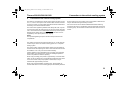
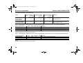
Th23_EA_degbfr_g.book Seite I Dienstag, 15. Februar 2005 2:03 14
Wasserheizgeräte
Water Heaters
Appareils de chauffage
Einbauanweisung
Installation Instructions
Instruction de montage
Thermo 230
Thermo 300
Thermo 350
Typ/Type Thermo 230/300/350
Thermo 231
Thermo 301
Typ/Type Thermo 231/301
mit Steuergerät 1572D
with Control Unit 1572D
avec boîtier de commande 1572D
01/2005
Th23_EA_degbfr_g.book Seite III Dienstag, 15. Februar 2005 2:03 14
Thermo 230/231/300/301/350
Improper installation or repair of \/Vebasto heating and cooling systems can cause fire or the leakage of deadly
carbon monoxide leading to serious injury or death.
To install and repair Webasto heating and cooling systerns you need to have completed a Webasto training course
and have the appropriate technical documentation, special tools and special equipment.
NEVER try to install or repair Webasto heating or cooling systems if you have not completed a Webasto training
course, you do not have the necessary technical skills and you do not have the technical documentation, tools and
equiprnent available to ensure that you can complete the installation and repair work properly.
ALWAYS carefully follow Webasto installation and repair instructions and heed all WARNINGS.
Webasto rejects any liability for problems and damage caused by the system being installed by untrained personnel.
La réparation ou l'installation impropre des systèmes de chauffage et de refroidissement Webasto peut conduire à
l'incendie de l'appareil ou encore à des fuites mortelles de monoxyde de carbone pouvant entraîner de graves
lésions voire même la mort.
Pour l'installation ou la réparation des systèmes de chauffage ou de refroidissement Webasto, il est nécessaire
d'avoir une formation Webasto, une documentation technique, des outils spécifiques et des équipements particuliers.
N'essayez JAMAIS d'installer ou de réparer un système de chauffage ou de refroidissement Webasto si vous n'avez
pas suivi avec succès la formation Webasto et obtenu ainsi les capacités techniques indispensables et si vous ne
disposez pas de la documentation technique, des outils et des équipements nécessaires à une installation ou à une
réparation dans les règles de l'art.
TOUJOURS suivre scrupuleusement les instructions Webasto relatives à l'installation et à la réparation des appareils
et tenir compte de toutes les MISES EN GARDE.
Webasto décline toute responsabilité, en cas de problème ou de dommage causé par un système ayant été installé
par du personnel non qualifié.
III
Th23_EA_degbfr_g.book Seite IV Dienstag, 15. Februar 2005 2:03 14
Thermo 230/231/300/301/350
Inhaltsverzeichnis
Contents
1
2
3
4
5
6
7
8
9
10
11
12
13
14
1
2
3
4
5
6
7
8
9
10
11
12
13
14
Gesetzliche Bestimmungen für den Einbau . . . . . . . . . . . . 1
Verwendung / Ausführung . . . . . . . . . . . . . . . . . . . . . . . . . . 3
Einbau . . . . . . . . . . . . . . . . . . . . . . . . . . . . . . . . . . . . . . . . . . 4
Einbaubeispiel für Thermo 230/300/350 . . . . . . . . . . . . . . 11
Einbau Umwälzpumpe . . . . . . . . . . . . . . . . . . . . . . . . . . . . 12
Anschluss an das Kühlsystem des Fahrzeuges . . . . . . . 17
Brennstoffversorgung . . . . . . . . . . . . . . . . . . . . . . . . . . . . 18
Brennluftversorgung . . . . . . . . . . . . . . . . . . . . . . . . . . . . . 19
Abgasleitung . . . . . . . . . . . . . . . . . . . . . . . . . . . . . . . . . . . . 20
Elektrische Anschlüsse . . . . . . . . . . . . . . . . . . . . . . . . . . . 21
Erstinbetriebnahme . . . . . . . . . . . . . . . . . . . . . . . . . . . . . . 28
Wartung . . . . . . . . . . . . . . . . . . . . . . . . . . . . . . . . . . . . . . . . 29
Störungen . . . . . . . . . . . . . . . . . . . . . . . . . . . . . . . . . . . . . . 20
Technische Daten . . . . . . . . . . . . . . . . . . . . . . . . . . . . . . . . 32
Statutory regulations governing installation . . . . . . . . . . . 35
Use / version . . . . . . . . . . . . . . . . . . . . . . . . . . . . . . . . . . . . . 37
Installation. . . . . . . . . . . . . . . . . . . . . . . . . . . . . . . . . . . . . . . 38
Installation example for the Thermo 230 / 300 / 350 heater . . . 45
To install the circulating pump . . . . . . . . . . . . . . . . . . . . . . 46
Connection to the vehicle cooling system. . . . . . . . . . . . . 51
Fuel supply . . . . . . . . . . . . . . . . . . . . . . . . . . . . . . . . . . . . . . 52
Combustion air supply . . . . . . . . . . . . . . . . . . . . . . . . . . . . 53
Exhaust pipe . . . . . . . . . . . . . . . . . . . . . . . . . . . . . . . . . . . . 54
Electrical connections . . . . . . . . . . . . . . . . . . . . . . . . . . . . . 55
Initial start-up . . . . . . . . . . . . . . . . . . . . . . . . . . . . . . . . . . . . 62
Maintenance . . . . . . . . . . . . . . . . . . . . . . . . . . . . . . . . . . . . . 63
Troubleshooting . . . . . . . . . . . . . . . . . . . . . . . . . . . . . . . . . . 64
Technical data . . . . . . . . . . . . . . . . . . . . . . . . . . . . . . . . . . . 66
Sommaire
1
2
3
4
5
6
7
8
9
10
11
12
13
14
IV
Dispositions légales concernant le montage . . . . . . . . . . 69
Utilisation / version . . . . . . . . . . . . . . . . . . . . . . . . . . . . . . . 71
Installation . . . . . . . . . . . . . . . . . . . . . . . . . . . . . . . . . . . . . 72
Exemple d'installation pour le Thermo 230/300/350 . . . . 79
Installation de la pompe de circulation . . . . . . . . . . . . . . . 80
Raccordement au circuit de refroidissement du véhicule 85
Alimentation en carburant . . . . . . . . . . . . . . . . . . . . . . . . . 86
Alimentation en air de combustion . . . . . . . . . . . . . . . . . . 87
Conduite d'échappement . . . . . . . . . . . . . . . . . . . . . . . . . . 88
Branchements électriques. . . . . . . . . . . . . . . . . . . . . . . . . 89
Première mise en service . . . . . . . . . . . . . . . . . . . . . . . . . 96
Entretien . . . . . . . . . . . . . . . . . . . . . . . . . . . . . . . . . . . . . . . . 97
Dysfonctionnements . . . . . . . . . . . . . . . . . . . . . . . . . . . . . 98
Caractéristiques techniques . . . . . . . . . . . . . . . . . . . . . . . . 100
Th23_EA_degbfr_g.book Seite 35 Dienstag, 15. Februar 2005 2:03 14
Thermo 230/231/300/301/350
1
Statutory regulations governing installation
Statutory regulations governing installation
1.1. Statutory regulations governing installation
The Thermo 230 / Thermo 231 / Thermo 300 / Thermo 301 / Thermo 350
heater has been type-tested and approved in accordance with EC
Directives 72/245/EEC (EMC) and 2001/56/EC (heater) with the
following EC permit numbers:
e1*72/245*95/54*1010*XX
e1*2001/56*0007*00 for Thermo 230
e1*2001/56*0008*00 for Thermo 300
e1*2001/56*0009*00 for Thermo 350
e1*2001/56*0010*00 for Thermo 231
e1*2001/56*0011*00 for Thermo 301
Installation is governed above all by the provisions in Annex VII of
Directive 2001/56/EC.
NOTE:
The provisions of these Directives are binding within the territory
governed by EU Directive 70/156/EEC and should similarly be
observed in countries without specific regulations.
(Extract from Directive 2001/56/EC Annex VII)
1.7.1. A clearly visible indicator within the user's field of vision must
show when the heater is switched on or off.
2. Regulations for installation in the vehicle
2.1. Scope
2.1.1.Subject to the provisions of paragraph 2.1.2, internal combustion
heaters must be installed in accordance with the requirements
contained in this Annex.
2.1.2.In the case of class O vehicles of class O (trailers) with heaters for
liquid fuel, it is presumed that these vehicles comply with the
requirements in this Annex.
2.2. Position of the heater
2.2.1.Parts of the vehicle body and other components in the immediate
vicinity of the heater must be protected against excessive heat and the
danger of contamination by fuel or oil.
2.2.2.The internal combustion heater must not pose a fire hazard even
when overheated. This requirement is deemed to have been met if care
is taken during installation to ensure an adequate distance from all parts,
as well as adequate ventilation and if fire-resistant materials or heat
shields are used.
2.2.3.In class M2 and M3 vehicles the heater must not be installed in the
passenger cabin. A device in a sealed cover, which also meets the
requirements set out in paragraph 2.2.2, may be used, however.
2.2.4.The plate mentioned in paragraph 1.4 (model plate) or a duplicate
thereof ( duplicate model plate ) must be fitted in such a way that it is still
clearly legible when the heater has been installed in the vehicle.
2.2.5. When positioning the heater, all reasonable precautions must be
taken to minimise the risk of personal injury or damage to items in the
vehicle.
2.3. Fuel supply
2.3.1.The fuel filler neck must not be located in the passenger
compartment and must have a tightly fitting cap to prevent any fuel
leaks.
2.3.2.The type of fuel and the fuel filler neck must be clearly identified
on heaters for liquid fuel, for which the fuel supply is separate from the
fuel supply for the vehicle.
2.3.3.A sign must be affixed to the fuel filler neck warning that the heater
must be switched off before refuelling. An identical warning must also be
included in the manufacturer's operating instructions.
35
Th23_EA_degbfr_g.book Seite 36 Dienstag, 15. Februar 2005 2:03 14
Statutory regulations governing installation
2.4. Exhaust system
2.4.1.The exhaust outlet must be positioned in such a way that exhaust
fumes cannot get into the interior of the vehicle through ventilation
devices, hot-air inlets or open windows.
2.5. Combustion air inlet
2.5.1.The air for the combustion chamber of the heater must not be
extracted from the passenger cabin of the vehicle.
2.5.2.The air inlet must be positioned in such a way that it cannot be
obstructed by other objects.
2.6. Hot air inlet
2.6.1.The supply of heating air must consist of either fresh air or
recirculated air and must be taken from a clean area which cannot be
contaminated by exhaust fumes from the engine, the internal
combustion heater or any other source in the vehicle.
2.6.2.The inlet line must be protected by a grating or other suitable
means.
2.7. Hot air outlet
2.7.1.Hot air lines within the vehicle must be positioned or protected in
such a way as to exclude all risk of injury or damage caused by direct
contact.
2.7.2.The air outlet must be positioned or protected so that it cannot be
obstructed by other objects.
2.8. Automatic control of the heating system
When the engine stops, the heating system must cut out automatically
and the fuel supply must be stopped within 5 seconds.
The heating system may remain in operation if a manual unit has
already been activated.
36
Thermo 230/231/300/301/350
IMPORTANT
Failure to follow the installation instructions and the notes contained
therein will lead to all liability being refused by Webasto The same
applies if repairs are carried out incorrectly or with the use of parts other
than genuine spare parts. This will result in the invalidation of the type
approval for the heater and therefore of its homologation / EC type
licence.
1.2. Provisions relating to the installation in rail vehicles
For heater models Thermo 230 / 300 /350 Rail designed for installation
in rail vehicles, a design certification acc. to § 33 EBO (= Federal
Railway Authority) has been issued with the following approval number:
EBA 32AZ3/0141/04.
Particular attention must be given to incidental provision 1.6 of the design certification:
Should the manufacturer, operator or service technician gain knowledge
of any accidents and damage (caused by fire, explosion, escape of Diesel fuel or heating oil EL) that may have occurred despite proper use of
the heater, he is required to immediately notify the certifying body thereof.
Th23_EA_degbfr_g.book Seite 37 Dienstag, 15. Februar 2005 2:03 14
Thermo 230/231/300/301/350
2
Use / version
Use / version
2.1. Use of the water heaters
The Webasto Thermo 230/231/300/301/350 water heaters are used in
connection with the vehicle's own heating system
2.2.
– to heat the passenger cabin,
– to defrost the vehicle windows and
– to preheat water-cooled engines.
Water heater for “diesel”
with 23 kW heat current (20000 kcal/h)
Versions
Thermo 230
Thermo 231
The water heaters operate independently of the engine and are
connected to the cooling system, the fuel system and the electrical
system of the vehicle.
The heater is approved for heating the passenger cabin or the driver’s
cab, but not to heat a cargo space used to transport hazardous
substances.
NOTE:
The Thermo 230/300/350 heaters are only licensed for horizontal
installation.The Thermo 231/301 heaters are licensed for vertical and
horizontal installation.
Water heater for “diesel”
with 23 kW heat current (20000 kcal/h)
Thermo 300
Water heater for “diesel”
with 30 kW heat current (26000 kcal/h)
Thermo 301
Water heater for “diesel”
with 30 kW heat current (26000 kcal/h)
Thermo 350
Water heater for "diesel" fuel
with 35 kW heat current (30000 kcal/h)
The water heaters are designed for 24 V.
On request, and depending on the configuration, the heater may be
equipped with a nozzle holder preheating system.
37
Th23_EA_degbfr_g.book Seite 38 Dienstag, 15. Februar 2005 2:03 14
Installation
3
Installation
IMPORTANT
– The statutory regulations governing installation on pages 35 and 36
must be adhered to.
– If the water heater is to be operated in a separately installed heating
system, prior to installation an installation planning report must
always be submitted to Webasto for approval. If this approval is not
obtained, all warranty and liability claims will be void. The water
heater has been designed, tested and approved for specific bus
requirements.
NOTE:
Check the installation situation of the relevant vehicle type.
3.1. Installation location
The heater and circulating pump are to be integrated into the cooling
system (or in a separate heating system).
The heater must be installed in as low a position as possible to allow the
heater and circulating pump to be bled automatically. This is particularly
important as the circulating pump is not self-priming.
If it is not possible to install the heater in the vehicle’s engine bay it may
be installed in a box. The installation box must have sufficient external
ventilation to ensure that the maximum temperature of 85°C is not
exceeded in the box.
Bear in mind the space required for servicing accessibility (for example
for removing the combustion chamber) (see Figures 1, 2, 5, and 10)
when installing the heater.
38
Thermo 230/231/300/301/350
3.1.1.
Installation Location in Rail Vehicles
When the heater is to be installed in rail vehicles, it should be installed
either in the engine room (e.g. locomotive) or underfloor in an installation
box at the wagon body (e.g. railcar). Other installation locations require
Webasto's approval in writing.
NOTE
No antivibration mounts must be used for securing the heater in rail
vehicles.
Th23_EA_degbfr_g.book Seite 39 Dienstag, 15. Februar 2005 2:03 14
Thermo 230/231/300/301/350
Installation
1
2
3
4
6
7
8
12
11
9
1
2
3
4
5
6
7
8
9
10
11
12
5
CO2 setting
Combustion air intake
Exhaust fume outlet
Fuel intake
Fuel discharge
Space required to remove the burner chamber
Coolant intake
Temperature limiter
Swivel range, at least approx. 25°
Max. swivelled burner
Coolant outlet
Temperature sensor
10
Fig. 1:
Dimensions of the Thermo 230 / 300 / 350 heater (horizontal installation)
39
Th23_EA_degbfr_g.book Seite 40 Dienstag, 15. Februar 2005 2:03 14
Installation
Thermo 230/231/300/301/350
610
1
415
ø38
ca 226
2
3
6
ca.440
26,5
4
302,5
382
ø70,3
ca.160
5
7
8
ca.145
200
12
11
ca. 25°
ca.440
9
10
Fig. 2:
40
Dimensions of the Thermo 230 / 300 / 350 Rail heater
1
2
3
4
5
6
7
8
9
10
11
12
CO2 setting
Combustion air intake
Exhaust fume outlet
Fuel intake
Fuel discharge
Space required to remove the burner chamber
Coolant intake
Temperature limiter
Swivel range, at least approx. 25°
Max. swivelled burner
Coolant outlet
Temperature sensor
Th23_EA_degbfr_g.book Seite 41 Dienstag, 15. Februar 2005 2:03 14
Thermo 230/231/300/301/350
Installation
3.2. To install the Thermo 230 / 300 / 350 heater
The heater may be secured either with four screws M8 (Figure 4/1) or
with four screws and nuts (Figure 4/2).
Fig. 3:
Horizontal installation position
1
1
2
2
2
2
Fig. 4:
1
D
1
Hole pattern for Thermo 230 / 300 / 350 heater
4.5 mm diameter for using M4 screws,
2.9 mm diameter for using B3.9 self-tapping screws
41
Th23_EA_degbfr_g.book Seite 42 Dienstag, 15. Februar 2005 2:03 14
Installation
Thermo 230/231/300/301/350
2
4
6
9
5
7
3
10
12
11
8
Fig. 5:
42
Dimensions of the Thermo 231 / 301 heater (vertical installation)
1
1
2
3
4
5
6
7
8
9
10
11
12
CO2 setting
Combustion air intake
Exhaust fume outlet
Fuel intake
Fuel discharge
Space required to remove the burner chamber
Coolant intake
Temperature limiter
Swivel range, at least approx. 25°
Max. swivelled burner
Coolant outlet
Temperature sensor
Th23_EA_degbfr_g.book Seite 43 Dienstag, 15. Februar 2005 2:03 14
Thermo 230/231/300/301/350
Installation
3.3. To install the Thermo 231 / 301 heater
The heater is to be secured with four M8 screws (Figure 7), body
washers and nuts.
IMPORTANT
The heat transfer base must be supported on a stable surface
connected to the floor of the car.
The securing screws are designed to fix the heater in position, not to
suspend it.
Fig. 7:
Fig. 6:
Hole pattern for the Thermo 231 / 301 heater
Vertical installation position
43
Th23_EA_degbfr_g.book Seite 44 Dienstag, 15. Februar 2005 2:03 14
Installation
3.4. Model plate
The model plate must be protected from damage and must be clearly
legible when the heater is installed (otherwise a duplicate model plate
must be used).
Thermo 230/231/300/301/350
3.5. Additional Type Plate
Heaters approved for use in rail vehicles are additionally identified by the
type plate illustrated below:
Feel the drive
Eisenbahn-BundesamtBauartzulassung Nr:
EBA 32AZ3/0141/04
Fig. 8:
Model plate for Thermo 230
Fig. 9:
44
Additional Type Plate
Th23_EA_degbfr_g.book Seite 45 Dienstag, 15. Februar 2005 2:03 14
Thermo 230/231/300/301/350
4
Installation example for the Thermo 230 / 300 / 350 heater
Installation example for the Thermo 230 / 300 / 350 heater
Water heating circuit – wall heater and roof duct heating system
1
2
3
4
5
6
7
8
5
Wall heater with blower
Heat exchanger at entry point
Heater
Circulating pump
Roof heat exchanger
Vehicle engine
Driver’s position heating system
Control element
3
1
4
6
7
1
1
2
1
9
8
Vorlauf Supply
Rücklauf Return
Fig. 10: Installation example for the Thermo 230 / 300 / 350 heater
45
Th23_EA_degbfr_g.book Seite 46 Dienstag, 15. Februar 2005 2:03 14
To install the circulating pump
5
Thermo 230/231/300/301/350
To install the circulating pump
The circulating pump must be installed as shown in Figures 11 and 12,
Figure 14 and 15, Figure 17 and 18 or Figures 20 and 21. Note the
installation position.
NOTE:
The pump ports and connection lines from the water intake and water
outlet must be flush (no stress).
5.1.
U 4814 circulating pump
Fig. 12: Hole pattern for the stand for U 4814 circulating pump
Delivery rate
(with water at 20°C)
∆
Fig. 11: U 4814 circulating pump
Installation position
46
Flow resistance
(with the pump stopped)
Fig. 13: Delivery rate and flow resistance
U 4814 circulating pump
Th23_EA_degbfr_g.book Seite 47 Dienstag, 15. Februar 2005 2:03 14
Thermo 230/231/300/301/350
5.2.
To install the circulating pump
Aquavent 5000 S circulating pump
99,5
249
53
60
32
131,5
38
31
38
23
110
225
Br- Sw+
0-90°
90°
Fig. 14: Aquavent 5000 S circulating pump
Installation position
Fig. 15: Hole pattern for the stand for Aquavent 5000 S
circulating pump
Delivery rate
(with water at 20°C)
Flow resistance
(with the pump stopped)
Fig. 16: Delivery rate and flow resistance
Aquavent 5000 S circulating pump
47
Th23_EA_degbfr_g.book Seite 48 Dienstag, 15. Februar 2005 2:03 14
To install the circulating pump
5.3.
Thermo 230/231/300/301/350
U 4851 circulating pump
279
115
53
60
32
31
500
38
38
23
110
63
6,5
24
100 *
90°
0-90°
* Clamping area of the stand clamp
Fig. 17: U 4851 circulating pump
Installation position
85
97,5
Br- Sw+
Fig. 18: Hole pattern for the stand for U 4851 circulating pump
Delivery rate
(with water at 20°C)
Flow resistance
(with the pump stopped)
Fig. 19: Delivery rate and flow resistance
U 4851 circulating pump
48
Th23_EA_degbfr_g.book Seite 49 Dienstag, 15. Februar 2005 2:03 14
Thermo 230/231/300/301/350
5.4.
To install the circulating pump
Aquavent 6000 S circulating pump
284
53
115
180,5
60
32
31
500
38
38
23
110
63
0-90°
6,5
24
100 *
85
90°
97,5
Br- Sw+
122,5
Fig. 21: Hole pattern for the stand for the Aquavent 6000 S
circulating pump
* Clamping area of the stand clamp
Fig. 20: Aquavent 6000 S circulating pump
Installation position
NOTE:
When connecting the circulating pump is must be ensured that the
volume flow does not drop below 1800 l/h !
Delivery rate
(with water at 20°C)
Flow resistance
(with the pump stopped)
Fig. 22: Delivery rate and flow resistance
Aquavent 6000 S circulating pump
49
Th23_EA_degbfr_g.book Seite 50 Dienstag, 15. Februar 2005 2:03 14
To install the circulating pump
5.5. Motor for the U 4851 / Aquavent 6000 S circulating pump
The U 4851 / Aquavent 6000 S circulating motor is fitted with a brushless
motor.
5.5.1.
Soft start
The motor starts slowly to protect its material.
It does not reach its maximum speed for approx. 5 seconds.
5.5.2.
Dry running protection (U 4851 only)
A dry running protection is integrated in the motor
for speeds >3300 rpm.
If the motor consumes less than 4 A of current in a timeframe of 1018
revolutions, it assumes that it is running dry. The motor is switched off
by the error motor (after approx. 10 seconds of operation or approx.
15 seconds after it was switched on).
5.5.3.
Blocking protection
If the speed falls to below 57 rpm the motor is switched off after approx.
1 second by the error mode. If the motor does not complete a full
revolution in 1 seconds despite the medium flow, it is also switched off
by the error mode.
5.5.4.
Error mode
The error mode switches off the motor in the event of faults. The motor
is switched to power-saving sleep mode by the error mode after approx.
5 seconds.
5.5.5.
Sleep mode
In sleep mode the internal consumers of the motor’s electronics are
switched off. The current consumption in this mode is then < 2 mA.
50
Thermo 230/231/300/301/350
5.5.6.
To reactivate the motor
The motor can be reactivated from sleep mode. This is done by
disconnecting it from the power supply for approx. 2 minutes. When the
voltage supply is reconnected the motor will restart in soft start mode.
5.5.7.
Reverse polarity protection
The motor does not have polarity reversal protection. The motor is
protected from polarity reversal by the wiring harness and a 25 A fuse.
Th23_EA_degbfr_g.book Seite 51 Dienstag, 15. Februar 2005 2:03 14
Thermo 230/231/300/301/350
6
Connection to the vehicle cooling system
Connection to the vehicle cooling system
The heater is connected to the vehicle cooling system as shown in Figures 1, 2, 5 and 10. The system must contain at least 10 litres of coolant.
A minimum of 20% of a good quality antifreeze should be maintained in
the heating circuit of the heater at all times.
The water hoses supplied by Webasto must always be used. If you do
not use these hoses, the hoses that you do use must comply with DIN
73411. The hoses must be installed without kinks and (to ensure perfect
bleeding of the heater) rising if possible. Hose connections must be
supported by hose clips to prevent them slipping.
off when there is a lack of coolant or the pump impeller is obstructed; it
may be restarted after approximately 2 minutes.
Also in the case of Thermo 230/231/300/301/350 heaters featuring
control unit SG 1572 D in combination with a programmed check of the
circulating pump, will the heater be switched off when there is a lack of
coolant.
NOTE:
The specified tightening torques of the hose clamps used must be
complied with.
Only pressure valves with an opening pressure of min. 0.4 bar and max.
2.0 bar may be used in the vehicle’s cooling system or in a separate
heating system.
The cooling system must be bled carefully before using the heater for
the first time or after replacing the coolant. The heater and lines should
be installed in such a way as to ensure static bleeding.
Perfect ventilation can be identified by the circulating pump operating
almost silently. Poor bleeding may cause the resetting temperature
limiter to trip whilst the heater is operating.
When using circulating pump U 4851, approximately 15 seconds after
switch-on the circulating pump is automatically switched off when there
is a lack of coolant or the pump impeller is obstructed; it may be
restarted after approximately 2 minutes.
When using Aquavent 6000 S circulating pump, approximately 45
seconds after switch-on the circulating pump is automatically switched
51
Th23_EA_degbfr_g.book Seite 52 Dienstag, 15. Februar 2005 2:03 14
Fuel supply
7
Fuel supply
The fuel is taken from the vehicle fuel tank or from a separate fuel tank.
7.1. Fuel lines
Fuel lines are to be installed with a gradient wherever possible to
prevent air inclusions. Connections within the line are to be secured with
hose clips if no mechanical screw connectors are used.
If fuel hoses are used, the hoses supplied by or available from Webasto
must generally be used. If you do not use these hoses, the fuel hoses
that you do use must comply with DIN 73379. Fuel hoses must not be
kinked or twisted and must be secured with clips approx. every 25 cm.
Materials commonly used in automobile manufacture, e.g. steel and
plastic lines made of plasticized, light-resistant and temperaturestabilized PA 11 or PA 12 (e.g. Mecanyl RWTL) as per DIN 73378 may
also be used for fuel lines taking into account the suitable connection
system in each case.
The following must be observed for the installation of fuel lines:
– The lines must be protected from the effects of high temperatures.
IMPORTANT!
The external casing on the heater may reach the ignition
temperature of diesel if it is operated without coolant.
– The lines must be protected from stone damage.
– Dripping or evaporating fuel must not be allowed either to
accumulate or to ignition hot parts or electrical equipment
It is not permissible to install a shut-off device in the return line!
IMPORTANT
Operation with a closed return line will damage the fuel pump.
Fuel may escape. Danger of fire!
52
Thermo 230/231/300/301/350
Unsupported fuel lines must be secured to prevent them sagging.
Do not install an additional fuel pump.
See pages 35 and 36 for the statutory regulations.
7.1.1.
Maximum dimensions of the fuel lines:
– Internal diameter for intake and return line: 6 mm (other diameters to
order).
– Maximum line length for each intake and return line: 10 m
– Maximum intake height: 2 m (we recommend the installation of a foot
valve if the max. intake height is used)
– Max. permissible suction height: 2 m
– Max. permissible pressure in flow and return lines: 0.3. bar
7.2. Fuel filter
A fuel filter supplied or approved by Webasto must be used (check the
flow direction). To avoid malfunctions the filter or filter insert is to be
replaced before the start of the cold weather.
Th23_EA_degbfr_g.book Seite 53 Dienstag, 15. Februar 2005 2:03 14
Thermo 230/231/300/301/350
8
Combustion air supply
Combustion air supply
Under no circumstances may the combustion air be taken from areas
occupied by people. The combustion air intake opening must not point
in the direction of travel. It must be located so that it cannot become
clogged with dirt or snow and cannot suck in splashing water.
Maximum dimensions of the air intake line:
– Internal diameter: 55 mm
– Maximum line length: 5 m without the exhaust extension
– Maximum bends: 270°
– Total length of air intake line and exhaust pipe max. 5m
The combustion air intake must not be routed above the exhaust outlet.
NOTE:
If the combustion air intake line cannot be installed so that it slopes
downwards, a water drain hole with a diameter of 4 mm is to be made at
its lowest point.
If the heater is installed in a general installation space near the vehicle’s
fuel tank, the combustion air must be taken in from the outside and the
exhaust fumes discharged into the atmosphere. The openings must be
splash-proof.
A ventilation opening is required if the heater is installed in an enclosed
box.
Thermo 230 / Thermo 231 / Thermo 300 / Thermo 301 30 cm2
Thermo 350
35 cm2
The size of the ventilation opening must be increased subject to
consultation with Webasto if the temperature in the box exceeds the
permitted ambient temperature of the heater (see Technical data).
53
Th23_EA_degbfr_g.book Seite 54 Dienstag, 15. Februar 2005 2:03 14
Exhaust pipe
9
Exhaust pipe
The opening of the exhaust pipe must not point towards the front of the
vehicle.
The exhaust pipe opening must be located so that it cannot become
clogged with snow and mud.
Rigid pipes of unalloyed or alloyed steel with a minimum wall thickness
of 1.0 mm or flexible piping of alloyed steel only must be used as
exhaust line. The exhaust pipe is secured to the heater using a clamping
collar, for example. See the statutory regulations for other requirements.
Maximum dimensions of the exhaust pipe:
– Internal diameter: 70 mm
– Maximum line length:
5 m without the combustion air intake extension
– Total length of air intake line and exhaust pipe max. 5m
– Maximum bend: 270°
NOTE:
If the exhaust line is installed near heat-sensitive parts, it must be
insulated.
54
Thermo 230/231/300/301/350
Th23_EA_degbfr_g.book Seite 55 Dienstag, 15. Februar 2005 2:03 14
Thermo 230/231/300/301/350
10
Electrical connections
Electrical connections
10.1. Heater connection
IMPORTANT HIGH VOLTAGE:
Danger of death. Disconnect the plug connection to the vehicle before
you open the heater.
Make the electrical connections to the heater as shown in Figure 23:
Automatic circuit diagram for water heaters type Thermo 230,
Thermo 231, Thermo 300, Thermo 301 and Thermo 350
Any plug designs that differ from the standard versions (Figures 23 and
24) are to be requested separately from Webasto.
Use the specified cable cross-sections.
Connect the negative and positive terminals of the heater controller
direct to the battery.
10.2. Connecting the controls
The heater can be switched on and off using the following Webasto
controls:
– Switch, see automatic circuit diagram Figure 23
– Timer, see circuit diagram Figure 24
10.3. Control module
The control module is installed in the heater.
10.4. Economy mode
The connection of the switch for economy mode is shown in the
automatic circuit diagram, Figures 23 and 24.
55
Th23_EA_degbfr_g.book Seite 56 Dienstag, 15. Februar 2005 2:03 14
Electrical connections
Thermo 230/231/300/301/350
10.5. Water Temperature Control Thresholds::
Heater
Auxiliary heating
0->1
1->control
idle period
Thermo 230.032
Thermo 300.031
Thermo 350.032
Thermo 230.126 Rail
Thermo 300.126 Rail
Thermo 350.126 Rail
10.5.1.
Parking heating
0->1
1->control
idle period
Economy setting
0->1
1->control
idle period
Comment
78
85
70
85
55
70
Standard data record
70
85
45
60
5
20
Engine start-up (>+60°C)
Preheat + heat preservation (>+40°C)
Freeze protection (>+0°C)
Pin Assignment of Cable Harness for Control Thresholds, Models Thermo 230 / Thermo 300 / Thermo 350 (Standard)::
Control unit function
Auxiliary heating
Parking heating
Economy setting
on/off
on
on
on
volts Connector
24 V
X3
24 V
X1
24 V
X3
Pin
5
5
4
Comment
only in conjunction with parking heater
switch connecting wire to control unit
only in conjunction with parking heater
NOTE:
Auxiliary heating has priority over the economy setting!
10.5.2.
Pin Assignment of Cable Harness for Control Thresholds, Models Thermo 230.126 / Thermo 300.126 / Thermo 350.126 (Rail)::
Control unit function
Auxiliary heating
Parking heating
Economy setting
on/off
on
on
on
volts
24 V
24 V
24 V
Connector
X3
X3
X3
NOTE:
Auxiliary heating has priority over the economy setting!
56
Pin
3
5
2
Comment
only in conjunction with parking heater
switch connecting wire to control unit
only in conjunction with parking heater
Th23_EA_degbfr_g.book Seite 57 Dienstag, 15. Februar 2005 2:03 14
Thermo 230/231/300/301/350
10.6. Legend for circuit diagrams
➀ Diagnostic connector
➁
➂
Digital timer P:
with positive at connection 10= Continuous operation
with immediate heating
Connection 10 open
= Variable heating duration
can be programmed
(10 min to 120 min);
Default setting 120 min
Plug assignment:
Plug
assignment
D1
D2
D3
D4
F1
F2
➃
➄
4-core
cable
0.75 gr
0.75 or
0.75 gn
0.75 br
Not occupied
Not occupied
7-core
cable
0.75 rt
0.75 or
0.75 bl
2.0 br
2.0 sw
2.0 rt/ws
Electrical connections
Cable cross-sections
< 7.5 m
7.5 - 15 m
0.75 mm2
1.5 mm2
1.0 mm2
1.5 mm2
1.5 mm2
2.5 mm2
2.5 mm2
4.0 mm2
4.0 mm2
6.0 mm2
Cable colours
bl
br
ge
gn
gr
or
rt
sw
vi
ws
blue
brown
yellow
green
grey
orange
red
black
violet
white
with connection to terminal 61 heating mode
Option
57
Th23_EA_degbfr_g.book Seite 58 Dienstag, 15. Februar 2005 2:03 14
Electrical connections
Item Designation
Thermo 230/231/300/301/350
Comment
Item Designation
Comment
S3
External activation
Circulating pump
A1
Heater
A2
Control module
SG 1572 D
B1
Flame sensor
Check polarity
S4
Switch
Economy mode
B2
Temperature sensor
Any polarity
S5
Switch
Auxiliary heating mode
B3
Temperature limiter
S6
Switch
Filter heater on
B4
Thermostat
For nozzle preheating
T
Temperature switch
Filter heater
B5
Thermostat
Alternative to B3
U1
Ignition spark generator
B6
Thermostat
For vertical installation (MV Y1)
U2
Ignition electrodes
Filter heater
W1
Wiring harness (1)
Heating cartridge
For nozzle preheating
W2
Wiring harness (2)
Blade-type fuse DIN 72581 Part 3
W3
Wiring harness (3)
Plug connector, 6-pin
E
E1
F1
Fuse 25 A
Switch
F2
Fuse 25 A
Blade-type fuse DIN 72581 Part 3
A
F3
Fuse 5 A
Blade-type fuse DIN 72581 Part 3
C
Plug connector, 1-pin
Blade-type fuse DIN 72581 Part 3
D
Plug connector, 4-pin
Blade-type fuse DIN 72581 Part 3
F
Plug connector, 2-pin
Blade-type fuse DIN 72581 Part 3
O
Plug connector, 2-pin
F4
F5
F6
Fuse 25 A
Fuse 5 A
Fuse 5 A
F7
Fuse 5 A
Blade-type fuse DIN 72581 Part 3
Q
Plug connector, 2-pin
H1
Light
Indicator
X1
Plug connector, 6-pin
H2
Light
Flame indicator
X2
Plug connector, 2-pin
H4
Heating symbol on the display
Power-on indicator (in item P)
X3
Plug connector, 8-pin
X4
Plug connector, 12-pin
X5
Plug connector, 4-pin
K4
Relay
M1
Motor
Combustion air fan
X6
Plug connector, 4-pin
M2
Motor
Circulating pump
X7
Plug connector, 7-pin
P
Digital timer, standard (1531) For programmed operation
Y1
Solenoid valve
S1
Switch
58
ON/OFF
Th23_EA_degbfr_g.book Seite 59 Dienstag, 15. Februar 2005 2:03 14
Thermo 230/231/300/301/350
Electrical connections
58
75 (15)
61
30
58
75 (15)
61
30
A
F3
F1
F2
S4
C
1
X3
5
6
3
3
4
3
3
3
2
3
1
2
3
6
5
4
4
1
D
3
W2
X1
S1
S3
W1 A
1
sw
5
5
or
1
3
4
2,0 mm² rt/ws
2,0 mm² rt
F
D
1
2
3
1
2
4
1
2
34
F
3
1
2
4
X1
2
2
M1
U1 B6 B3/B5 B2
6
2,0 mm² br
6
H1
M
2
-
U1
ϑ
B6
M
E1
2,0 mm² sw
U2
31
6
X3
1 35 7
2
B4
+ SE
M2
5
X2
1
A1
3
4
1
A2
X2
E1
2
bl
C
A2 B1 Y1
1
M1
Y1
B3
ϑ
B5
ϑ
2 4 6 8
ϑ
B2
H2
B1
A1
31
Fig. 23: System circuit for Thermo 230 / 231 / 300 / 301 / 350 24V with control module 1572 D, with switch, for legend see page 57 and 58
59
Th23_EA_degbfr_g.book Seite 60 Dienstag, 15. Februar 2005 2:03 14
Electrical connections
Thermo 230/231/300/301/350
58
75 (15)
61
30
58
75 (15)
61
30
A
4
F3
F1
F2
S4
2
1
X1
P
2
H4
5
6
3
3
4
3
3
3
2
3
1
D
3
W2
11
10
C
1
X3
S3
8
W1 A
1
sw
5
5
or
1
3
2,0 mm² rt/ws
F
D
1
2
3
1
2
4
1
7
4
4
2,0 mm² rt
2
1
X1
2
2
U1 B6 B3/B5 B2
6
2,0 mm² br
6
A1
B4
M
2
5
6
X3
1 35 7
2
+ SE
M2
3
4
X2
1
E1
2
1
A2
X2
A2 B1 Y1
1
bl
C
-
U1
ϑ
B6
M
E1
2,0 mm² sw
U2
31
2
4
X4
M1
34
F
3
H1
12
1
2
3
6
5
4
M1
Y1
B3
ϑ
B5
ϑ
2 4 6 8
ϑ
B2
H2
B1
A1
X4
3
1 2
4
7
9
31
Fig. 24: System circuit for Thermo 230/231/300/301/350 24V with control module 1572 D, with standard timer, for legend see page 57 and 58
60
Th23_EA_degbfr_g.book Seite 61 Dienstag, 15. Februar 2005 2:03 14
Thermo 230/231/300/301/350
Electrical connections
Fig. 25: System circuit for Thermo 230 / 300 / 350 Rail 24V with control module 1572 D, with standard timer, for legend see page 57 and 58
61
Th23_EA_degbfr_g.book Seite 62 Dienstag, 15. Februar 2005 2:03 14
Starting the heater for the first time
11
Starting the heater for the first time
NOTE:
Refer to the safety instructions in the operating and maintenance
instructions.
The operating and maintenance instructions must be read through
without fail before starting the heater.
After you have installed the heater, bleed the water system and the fuel
supply system carefully. Follow the instructions supplied by the vehicle
manufacturer for this purpose.
Conduct a trial of the heater to check all the water and fuel connections
for leaks and to ensure that they are secure. If the heater suffers a fault
during operation, the fault must be located and remedied.
62
Thermo 230/231/300/301/350
Th23_EA_degbfr_g.book Seite 63 Dienstag, 15. Februar 2005 2:03 14
Thermo 230/231/300/301/350
12
Maintenance
Maintenance
Periodic service activities have to be performed in accordance with
Chapter 8 and Appendix A of the Workshop Manual.
When the heater is operated in rail vehicles, maintenance chart / test
certificate item no. 90 087 22 is to be used.
63
Th23_EA_degbfr_g.book Seite 64 Dienstag, 15. Februar 2005 2:03 14
Troubleshooting
13
Troubleshooting
13.1. Fault lock-out
If it recognises one of the following fault features, the heater will conduct
a fault lock-out.
If several fault lock-outs occur in sequence, the heater will be disabled.
Flashing pulse signals are output by the operation indicator light for
heaters with control module 1572D. The combustion air blower and the
circulating pump will be shut down after approx. 120 seconds.
13.1.1. Faults when the heater is switched on:
Short-circuit or break
– Water temperature sensor
– Flame sensor
– Burner motor
– Solenoid valve
13.1.2. Faults during the start procedure:
– A flame is detected by the photo-electric controller before the high
tension ignition spark is triggered.
– No flame identified approx. 25 seconds after the heater is started.
– Short-circuit / Break or dry operation (if programmed) of the
circulating pump.
If you use the U 4851 circulating pump, the pump will cut out
automatically approx. 15 seconds after it is switched on if there is
insufficient coolant or the pump impeller is blocked automatically and
can be restarted after approx. 2 minutes.
64
Thermo 230/231/300/301/350
13.1.3. Faults whilst the heater is operating:
– The voltage level falls below the lower threshold of approx. 21 V for
a period of 20 seconds.
– Break in combustion for longer than 10 seconds.
– Short-circuit in the water temperature sensor.
– Break in the water temperature sensor.
– Short-circuit in the flame detector.
– Break in the flame detector.
– Short-circuit in the solenoid valve.
13.1.4. Faults whilst the heater is shutting down:
Detection of a flame over than 30 seconds after the start of the shutdown cycle, with only the circulating pump operating during the following
90 seconds.
13.1.5. Faults due to overheating:
If the heater overheats the temperature limiter/thermostat will complete
a fault lock-out.
Depending on the heater equipment:
– The button on the temperature limiter must be reset.
– The thermostat will be reset automatically when the heater has
cooled down.
The fault lock-out can be cancelled by switching the heater off and on
again.
Th23_EA_degbfr_g.book Seite 65 Dienstag, 15. Februar 2005 2:03 14
Thermo 230/231/300/301/350
13.2. Fault code output on heaters with control module 1572D
If the system is equipped with a standard timer, a fault message appears
on the display of the timer after a fault occurs.
Troubleshooting
13.2.1. To reset the heater after a fault lock-out
To reset the heater after a fault lock-out, switch on the heater and cut the
power supply to it during the starting process.
NOTE
If the system is operated with a switch, the nature of the fault is indicated
by a flashing code on an indicator light during the run-on time of the
heater. After five short signals, count the long flashes. The flashes
correspond to the number in the table below:
F 01
No start
F 02
Flame failure *
F 03
Undervoltage or overvoltage
F 04
Flame simulation identified during start-up or shut-down
F 05
Flame detector defective
F 06
Temperature sensor defective
F 07
Solenoid valve defective
F 08
Blower motor defective
F 09
unused
F 10
Temperature limiter defective / Overheating
F 11
Ignition spark generator defective
F 12
Fault lock-out due to repeated malfunction or
repeated flame failure
(8x no start-up or 5x flame failure)
*
On the Thermo 231 and 301, if the overheating thermostat trips
this is saved as a flame failure (F 02) in the control module
65
Th23_EA_degbfr_g.book Seite 66 Dienstag, 15. Februar 2005 2:03 14
Technical data
14
Technical data
Except where limit values are specified, these technical data refer to the
usual heater tolerances of ± 10% at an ambient temperature of +20°C
and at the rated voltage.
NOTE:
The assignment of circulating pumps to heaters must be made using the
water-side resistors.
14.1. Fuel
The diesel fuel specified by the manufacturer must be used. Heating oil
of class EL (not heating oil class L) can also be used as long as it of
standard German market quality.
We know of no negative influences due to additives.
If fuel is extracted from the vehicle’s tank, follow the additive instructions
issued by the vehicle manufacturer.
If fuel is extracted from a separate fuel tank, a winter diesel or equivalent
winter PME fuel must be used in temperatures below 0°C. Media to
improve the flow properties of the fuel may also be used.
If you change to low-temperature fuel, the heater must be operated for
approx. 15 minutes so that the fuel line, filter and fuel pump are filled
with the new fuel.
66
Thermo 230/231/300/301/350
Th23_EA_degbfr_g.book Seite 67 Dienstag, 15. Februar 2005 2:03 14
Thermo 230/231/300/301/350
Heater
Type
EC type approval number
Model
Heating flow
Technical data
e1*2001/56*
kW
(kcal/h)
Fuel
Fuel consumption
kg/h
Rated voltage
VOperating voltage range
VRated power consumption (without circulating pump)W
Max. ambient temperature during operation
(Heater, control module, circulating pump)
C°
Max. storage temperature (control module)
C°
Max. operating pressure
bar
Capacity of the heat exchanger
I
Minimum capacity of the system
I
CO2 in exhaust gas at rated voltage
% v/v
Heater dimensions
mm
(Tolerance ± 3 mm)
mm
mm
Weight
kg
Thermo 230
Thermo 230
0007*--
Thermo 231
Thermo 300
Thermo 301
Thermo 231
Thermo 300
Thermo 301
0010*-0008*-0011*-High pressure atomiser
23
30
(20 000)
(26 000)
Diesel / Heating oil EL
2,5
3,3
24
20...28
65
110
-40... + 85
Thermo 350
Thermo 350
0009*-35
(30 000)
3,7
140
+110 max.
0,4...2,0
1.8 I
10.00 I
10,5 ± 0,5
Length 610
Width 246
Height 220
19
67
Th23_EA_degbfr_g.book Seite 68 Dienstag, 15. Februar 2005 2:03 14
Technical data
Thermo 230/231/300/301/350
Circulating pump
Delivery rate
Rated voltage
Operating voltage range
Rated power consumption
Dimensions
(Tolerance ± 3 mm)
I/h
VVW
mm
mm
mm
kg
Weight
U 4814
5200 (against 0.15 bar)
24
20...28
104
Length 228.5
Width 100
Height 105
2,1
Optional Fuel Filter Heater
Filter heater
Rated power consumption
Rated voltage
Switch-on point
Switch-off point
68
W
VC°
C°
240
24
0,5 ± 2,5
5,5 ± 2,5
Aquavent 5000 S
5200 (against 0.15 bar)
24
20...28
104
Length 249
Width 100
Height 105
2,2
U 4851
6000 (against 0.4 bar)
24
18...32
215
Length 279
Width 115
Height 110
2,7
Aquavent 6000 S
6000 (against 0.4 bar)
24
18...32
215
Length 284
Width 115
Height 110
2,95