1
INSTRUCTION MANUAL
EP-KB Series
PRECISION INDUSTRIAL BALANCES
M0DEIS:WXB
n3-20KB
EP-40KB
EP-blKB
EP-60KB
A&D MERCURY PTY. LTD.
32 Dew St, Thebarton, S.A., 5031
Telephone (08)3523033
Facsimile (08)3527409
Introduction ...........................................................................................
..
Speclf~cations.......................................................................................
Installation ..............................................................................................
Page 3
Page 4
Page 5
Power Requirements .......................................................................
Page 6
Changing the Fuse .............................................................................
Page 6
.
.
Best Conditions for Weighing .................................... ...................... Page 6
Calibration .............................................................................................. Page 7
Parameter Settings ...........................................................................Page 9
The Weighing Modes ........................................................................ Page I I
. .
The Welghlng Units .................................................... .................... Page 12
Display and Key Functions ..............................................................
Page 14
Operation ................................................................................................
Page 16
Weighing .......................................... ................................................... Page 16
Weighing .In ........................................................................................ Page 16
Weighing .Out ....................................................................................
Page 16
Percentage Function ......................................................................... Page 17
Counting Functions .................................. :......................................... Page 17
Setting a Unit Weight into Memory ................................................. Page 18
Printing with AD-81 17 ....................................................................... Page 19
Underhook Weighing ........................................................................ Page 19
Interface .................................................................................................. Page 20
Specifications ..................................................................................
?age 20
AD-81 17 & Other Devices ................................................................ Page 20
Transmission Modes .......................................................................... Page 21
Command Mode Timing (RS-232C) ......................................... .
Page 21
Data Format .........................................................................................
Page 22
Circuit Diagram ...................................................................................
Page 23
Computer Programs ...........................................................................
Page 24
Appendix ..................................................................................................
Page 25
Calibration With Adjustments ......................................................... Page 26
;
:3987.
.
.
lnlernalional Division A8D Company Lid
Warranty rights vary from country to -try
but it is the general intention of
A&D Co., Ltd., to offer customers a one year warranty on this product from the
day it is purchased. In some countries consumer protection legislation states
that your dealer is responsible for offering a warranty and under these
circumstances please refer to your local dealer.
In the U.S.A. the product (if defective) should be returned, freight prepaid by
the customer, to A&D Engineering Inc. in California and in Europe the
product can be returned freight prepaid to A&D Instruments GmbH in
Frankfurt, West Germany. Elsewhere the product can be returned to A&D Co.,
Ltd. in japan. In any event please contact your nearest A&D office, before
shipping, to confirm that the product is covered by this warranty. Simple
repairs can be carried out by your local dealer under warranty and this may be
the fastest method of solving your problem.
This warranty only applies to product failures due to. defective materials
andlor workmanship. This warranty will be rendered invalid if, upon
inspection, it is found that the product was: Abused; used for a purpose for
which it was not designed; mishandled; placed in a hostile environment;
repaired by unauthorized personnel; improperly installed or not adjusted in
accordance with instructions given in this manual.
If repair under warranty is confirmed by A&D, then the product will be
repaired (or replaced, at the discretion of A&D) and then returned to the
customer at no extra cost.
Please note that this equipment generates, uses and can radiate radio
frequency energy. This equipment has been tested and has been found to
comply with the limits of a Class A computing device pursuant to Subpart J of
Part 15 of FCC rules. These rules are designed to provide reasonable protection
against interference when equipment is operated in a commercial
environment. If this unit is operated in a residential area it might cause sonie
interference and under these circumstances the user would be required to
take, at his own expense, whatever measures are necessary to eliminate the
interference.
(FCC = Federal Communications Commission in the U.S.A.)
Page 2
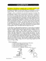
Please read this manual carefully before you use
your new balance!
Thank you for your A&D balance purchase! The EP series of high precision
industrial balances a r e the e n d p r o d u c t of years of research, design,
development a n d in-field testing. Every component has been carefully chosen
to p e r m i t o p t i m u m performance from the entire u n i t a n d e a c h balance
undergoes several levels of quality control before leaving the factory. The EP
series boasts full digital calibration, unit conversion to p o u n d s (avoir) and a
host of other features which make for unrivaled specifications.
-This Instruction
Manual covers the models:
EP-12KB
EP-20KB
*EP-41KB
*EP-40KB
EP-60KB
FEATURES:
3 Ultra stable weighing, high resolution and strong, reliable construction
Simple calibration via "Full Digital Calibration" function.
3 Convenient standard output interface, serial RS232C 1 / 0 and Current Loop.
3 Ability to tare up to the max. capacity of the balance via soft-touch key.
3 Ability to input a keyboard tare for known container weights.
3 Ability to set the gram weight of a 100%sample through the keyboard.
3 Ability to select any counting sample size.
3 Ability to input the the gram weight value for any calibration mass above 5kg.
3 Ability to store and recall 5 unit weights in on-board memory.
3 Ability to input unlimited unit weight/% values through the RS232C I/O.
3 Easy-to-read, cobalt blue fluorescent display.
3 Clear annunciators to indicate the status of various functions.
3 Optional underhook weighing capability for relative density experiments.
3 Swing-Arm feature to place the display panel in the most convenient position
3 Counting software with "Automatic Counting Accuracy Improvement".
3 Percentage function and unit conversion to lb, lb/oz, oz (avoir) or troy ounce.
2
-
mm n
0Kln000 0a
00000nm0
irnno-EP-B-aa-v.1
Page 3
'
Cal~bra!ior~
Adluslable Fee:
'Me. cow
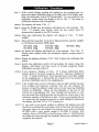
Options Include::
J
mi, w i h pi&
01PM.
Min. vrir v r = rurotw&n.
Underhook for:
EP-12KB & EP-2OKB
Underhook for:
EP-4OKB & EP-4lKB
Underhook for:
EPdOKB
Compact Printer
OP-04
OP-05
* OP-06
AD-8117
Page 4
Please see the BEST C O N D I T I O N S FOR W E I G H I N G section before selecting the
installation site for the Balance. Please unpack the balance carefully making
sure that no parts are mislaid during the process, including this manual!
LED on
means power connected
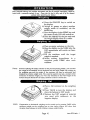
PARTS LIST:
1. Balance
2. Weighing Pan & Pan Support
3. Power Cable
4. 0.3A or 0.2A Fuse (Anti-Surge)
5. Unit Stickers "PC","%","lb","oz"."oztw
0 Place the Weighing Pan, with the Pan Support, gently onto the balance.
0 Level the balance by turning the Adjustable Feet until the spirit level (the
little bubble) is in the small circle of the Level Vial.
0 The Display Pod can be: raised, lowered, or the viewing angle adjusted by,
loosening or tightening the Angle Lock Screws on the Pod and Balance.
0 The Calibration Switch is situated in a small hole, normally covered by a
round plastic cover, near the metal arm that holds the Display Pod. The
plug can be removed by gently prying it away from the Pod. Use a small
tool to move the switch OFF^ (up - normal position) or ONU (down).
Power Cord
irnno-EP-8-ah-v. 1
Page 5
This balance will accept AC input voltages of; 100; 115,220 or 240V AC.
0 . The AC power requirements of your balance are unchangeable, depend
upon the original shipping destination of the balance and are clearly
marked on the case.
0 Power frequency can be either 50 or 60Hz. 0.3A Fuse=100/115V &
0.2A=220/240V.
o Please note that the balance ONJOFF key-switch only switches the display
on and off, not the power supply for the balance (note that the power LED
stays on). The balance may be kept connected to the electricity supply
overnight so that a warm up period will not be required each mominz, A
display of "----" means that there was a power cut during weighing so
press ON/OFF to start again.
0
%
a
If the display is blank and the light-emitfing diode on the ONJOFF keyswitch is not illuminated, a fuse may have blown. Unplug the power cable.
If an external AC fuse has not blown and you are certain that the balance is
receiving power, the fuse in the balance fuse holder may have blown.
0 Turn the fuse holder counterdockwise when opening, clockwise when
closing.
n If the fuse has blown, replace it with a 0.3A(100/115V) or 0 . U (220f240V)
fuse only. E this fuse immediately blows again, have the balance repaired.
NOTE: Uneven illumination of the display segments.
This condition may be mistaken as a fault but is in fact simply a result of the display not
having been run for some time. It may be rectified by running the display with all the
segments on until all the segments are evenly illuminated. See the section PARAMRFR
SETTINGS to learn how to run the display with all the display segments illuminated.
of a solid construction and preferably made of
a dense non-resonant material. The table should not be used for any other
purpose but weighing. If the balance is placed on the floor then care
should be taken in its location to make sure that it will not be damaged by
vehicles etc.
Corners of rooms are structurally firm and less prone to vibrations.
Optimum temperature is about 20°C/680Fat about 50% relative humidity.
The environment should be kept reasonably clean and dry but d o not
install the balance near a heater or in direct sunshine.
The balance must be as level as you can make it so that the mass on the
weighing pan can accelerate straight downwards. If the weighing table or
floor is not level, turn the adjustable feet on the balance until the ievel vial
indicates that the balance is horizontal.
Use a damp cloth and mild soap to clean the balance. Do not use solvents.
3 The weighing tabIe must be
0
0
0
0
0
Page 6
imno-EP-B-alb-v. 1
Calibration of the balance is required when it is initially installed, when
changing the installation site, and additionally every 90 days or so. It is necessary because the weight of a mass in one location is not necessarily the same in
another location. Also, with time and use, mechanical deviations can occur.
"Weight" = Mass x Acceleration due to the field of gravity of the Earth. The
internationally adopted value for gravitational acceleration is 9.80665m/s2
(32.174ft/s2) in a vacuum, however this varies by about M.3% depending on
how far you are from the Earth's center of mass. Mass distorts space in such a
way that the gravitatio'iai power of attraction is inversely proportional to the
square of the distance between material objects (if non-gravitational forces are
ignored) so gravitational acceleration is greatest at the poles, least at the
equator and decreases with altitude. The sun and the moon exert inconstant
forces of gravitational attraction. Air buoyancy (approximately 0.0012g +lo%
of air displaced per a n 3 at 20°C) and other factors also vary from location to
location and from time to time. By using an electromagnet to push up against
gravity - then calculating the degree of force (electriaty to the magnet) needed
to push against a mass - the balance finds the weight of the mass.
An EP balance is a high resolution instrument so a high quality non-magnetic
stainless steel weight should be used for span (maximum capacity) calibration.
Steel has a density of about 8.0g/un3 which means that a 20,000g mass has a
volume of about 2,500cm3. Thus, 2,500cm3 x 0.0012g = 3.0 grams of air
displaced whereas a brass weight would only displace about 2.8 grams of air
unless it had been adjusted via a cavity to mimic steel density. By international convention, weight in air is measured against the buoyant weight of
steel in air and EP-20 has a sensitive resolution of O.1g. EP balances have a
very easy calibration method called FDC (full digital calibration) which means
that the zero weight point and maximum capacity weight point are acquired
digitally at the press of a button. EP-12 requires a calibration weight of 10kg,
EP-20 requires a weight of 20kg, EP-40 & 41 require 40kg weights and EP-60
requires a weight of 60kg.
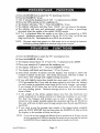
*Before calibrating:
0 Observe all the BEST CONDITIONS FOR WEIGHING.
0 Check that the weighing pan is clean.
0 Warm up the balance for at least 30 minutes.
a Get it is as level as you can make it.
gram mode.
a Check that it is weighing
.
/
CALIBRA?ION
imno-EP-6-a-V. 1
SWITCH
Cal~brar~on
Switch
~lastc~over
Page 7
Step 1. With a stable display reading and nothing on the weighing pan, remove the plastic calibration plug on the right side of the display pod.
Slide the calibration switch ON (downwards). Do not switch on the
calibration switch when the display is off, or "Err C (for Error in
Calibration method) will bc! displayed.
DISPLAY
The display will show "CAL 0".
Step 2. Press the TARE key, the display will blank for a few seconds. The
0" display then returns while the zero weight point is
"CAL
automatically entered by the FDC function.
F" (Full
DISPLAY After zero calibration the display will change to "CAL
weight).
Step 3. Place the Full Load (the 10,20,40 or 60kg maximum capacity weight)
on the balance and press TARE again.
*EP-12KB lOkg
*EP-41KB 40kg
*EP-60KB 60kg
*EP-20KB 20kg
eEP-40KB 40kg
DISPLAY AS before the display will blank for a few seconds. The "CAL F
display then returns while the maximum capacity weight point is
entered.
DISPLAY
Finally the display will show "CAL E n d to show that calibration has
ended.
Step 4. Switch the calibration switch off and replace the plastic plug, the
display will blank and then revert to normal weighing mode.
Calibration was easy wasn't it!
E it means Calibration Error
because there is too much weight on the pan. Likewise a display of
"-CAL E means Calibration Error because there is too little weight
on the weighing pan. A display like this would occur if you placed an
incorrect calibration mass on the weighing pan.
NOTEA: If YOU observe a display of "CAL
SOTE
B. If the weight value of your calibration mass has been defined by your
local weights and measures authority, then you can program the
balance to read the defined weight value of your mass (eg: 20,000.5g
instead of 20,000.0g). Please see the Appendix at the end of the
manual for programming this value through the keyboard. In fa&
any size mass from 5,000g upwards can be used but a mass close to the
maximum capacity of the balance is best. If you try to program the use
of a mass over the maximum capacity or under 5,000g for calibration,
the display will flash "Hi" or "Lo" to warn you.
NOTEC: If
you wish to use pound weights to calibrate this balance you will
first have to calculate the exact gram value of the mass and then enter
this gram value into the balance. For instance if you wish to calibrate
EP-20KB with a steel pound weight of 40.00045 lb exactly, then
multiply this by 453.59237g to find the gram value of 18,143.9 grams
and enter this value through the keyboard before zero calibration (see
Appendix for method).
Page 8
imno-EP-8-a/b-v, 1
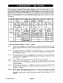
When the balance is shipped all the parameter settings are set to status 0 for groups "A"and "b"
(see table below) and they may not need to be changed. Group "A" settings cover the motion
detection band width, The display update rate, the integration time and running the display
segments continuously for even illumination. Group "b" settings cover the printing mode, data
output baud rate, parity setting and data format concerning the built-in RS-232C interface.
Please see the PARAMETER "A" & "b" SETTINGS sections following this section for more
information.
To enter parameter setting "A" and "b" mode:
Stcp 1. Switch OFF the display via the ONlOFF key. Next prcss thc TARE key and while
continuing to press TARE you should switch the display ON again via the ONlOFF
key.
- 00000" with a triangle below the "A". If you now press
the TARE key the triangle will move one step to the right and will be placed below
the first (left hand) "0".
DISPLAY The display will show "A"
Stcp 2.
Thismeans that you can now set this digit to the number you want (with rcfcrence to
the table below) by pressing the PRINT key once for the figure 1 and twice for thc
figure 2 etc. eg. "A - 20000".
Stcp 3.
Prcss TARE to move the triangle cursor to thc right and set thc ncxt digit.
Stcp 4.
Finally when all the digits are sct for group "A" you should return the cursor
underneath the lcttcr "A" and prcss PRINT to imprint th'c memory of thc balancc
with your settings.
- 00000" for setting thc parameters of thc RS-232C
interface. Set thcsc parameters as before and imprint in mcmory whcn the cursor is
under the "b" letter.
DISPLAY The display will change to "b
NOTE:
If you wish to change nothing in group "A" or "b" thcn you can simply press PRINT
first.while the cursor is still under the lettcr. You may at some timc wish to cntcr
parameter setting mode to check the prcscnt settings without changing any of thc
settings.
Page 9
.
Motion Band Width: In a perfect world an o b j j t resting on a weighing pan would be
completely immobile. Regrettably this is not a perfect world so we must tell the balance how
much motion should nevertheless be tonsidered as numotion. Tltis setting is the Motion Band
Width and if the movement of the object on the weighing pan is small enough to be inside this
band then the balance will regard the motion as no-motion and switch on the "STABLE*
Symbol. The "STABLE" symbol is the triangle a t the far left end of the display panel. If the
digit at position "A - XOOCXI" is set to 1 then the display will be regarded as stable if the amount
of movement when weighing is less than 32 digits. The position of the changing digits referred
to here is of course the far right end of the display, technically known as the "minimum
division" position The minimum division in the case of EP-20 is 0.1 because the balance weighs
to a resolution of O.lg in gram weighing mode. Thus with a setting of iZ digits the display of EP20 a n change between 1000.2gand 999.8g with the no-motion symbol remaining on. Incidentally
if the maximum capacity of an E
i' bajance is exceeded by more than +10 minimum divisions, then
ihe display will blank and "E" will come on to indicate an overload'error. A "-E" display
indicates an underload error.
Display Update Rate: This is a rather technical setting designed for busy peapie who
consider a display date update rate of 3 times per second a bit slow. Anyway it is possible to
increase the display update rate to 6 time per second with a setting of 1at position "A - 0x000".
Integration T i e Setking. This is the period of time in seconds .;faring which the baiane
adds weight data samples to produce an average sample for display. The number of samples per
second is 102/3SO during a 6 second period 64 samples will be added to produce an average (mean)
sample. A setting of 2 at position -A - OOXOO" would mean that only 16 samples would be added
during a 1"z second period. Theoretically a longer period would be better.
All Segments Illuminated: A setting of 1 at position "A - 000x0" will keep all the display
segments on so the display wiIl bum evenly {see note, page 6).
Zero Band: A setting of "0" at location "b-X0000" means that the ZERO key will only function
in a range of 2%
of the maximum capacity of the balance. A setting of "1"at location " b X W
mcans that the ZERO key will function over lOO% of the range up to maximum capacity. Thus ~f
the ZERO key is used as a RE-ZERO key to tare the we~ghtof a container, the balance wtll not
display the weight as NET rather than GROSS.
Print Mode Auto/ManuaI: In fact the rest of the group "b"settings can be ignored untca
you wish to connect a printer or computer to the RS-232C interface. If you connect a printer
(ADB117)or computer, then you can set one of the following five options at position "b - 0x000".
"0" The PFNT key will only work when the display is stablet'no-motion.
"1" The balance wiil accept a print key command but will wait for stable data.
"2" The balance will automatically output stable data once per we~ghingevent.
"3" The baiann wiil output data only when a computer commands it to.
"4" The balance will output a stream of data at the speed of display update rate.
-
Data Output
-
baud rate: Different devices require data to be fcd to them at different
speeds. Some computers may require data at a speed of 6CO baud white others may require 2,400
baud. AD23117 require data at 2,400 baud.
Parity Bit Setting: This is an error checking system for RS232C transmission and the setting
should be matched to the requirements of the receiving equipment. AD-8117 requires an EVEN
parity bit setting; (setting 0 at ?I - 000x0).
Data Format Stop Bit: Different equipment will require different data formats. AD-8117
requires 7 data bits and 1 stop bit; (setting 0 at "b - 0000X").
0 After setting the parameters of group " A and "b" (if they need to be
changed) you should proceed to set the status of the two extra weighing
modes in addition to the basic gram weighig mode.
0 At any one time the balance MODE key can be used to switch the display
from weighing in grams to two of the following six.extra weighing modes:
0 ."PC."
(pieces/counting)
0 "%"
(percentage)
0 "lb
(decimal pounds avoirdupois)
0 "lb/ozM(pounds and ounces avoirdupois)
0 "oz"
(ounces avoirdupois) or "ozt"' (troy ounces).
0 Unit stickers have been provided with the balance for sticking on the
display panel next to the two extra LEDs located above the gram LED. The
two extra weighing modes which you choose to select will depend on the
use to which you will put the balance. Some customers will wish to weigh
in grams (compulsory mode) or counting or percentage modes while
others will wish to weigh in grams or lb/oz or decimal pound modes etc.
0 Top LED- "%" or "pc." or " l b or "oz" or "ozt"
0 Middle LED- "%" or "pc." or " l b or "oz" or "ozt"
0 Bottom LED - "g" (cannot be changed)
To enter unitlfunction setting mode:
Step 1. Switch OFF the display via the ONlOFF key.
Step 2. Press the MODE key and, while continuing to press MODE, you
should switch the display ON again via the ONlOFF key.
DISPLAY
The display will show "--" (no unit) with the middle LED lit. This
means you may now define the weighing unit or function for the
middle LED.
Step 3. *If you now press the MODE key the display will change to "100" for
the percentage mode.
*If you press MODE twice the display will change to " P C (pieces)
*If you press MODE three times " L b (avoir decimal lb mode)
*If you press MODE four times "Lb.0" (avoir lb/oz mode).
*If you press MODE five times "0" (avoir oz mode).
*If you press MODE six times "t.0" (troy oz mode).
.
Step 4. Choose the mode you wish to have at the middle LED position and
press the SAMPLE % key to register your choice in the memory of
the balance. Stick the correct unit sticker next to the middle LED.
imno-EP-B-ah-v. 1
Page 11
DISPLAYThe display will show "--" with the top LED lit. This means that you
may now define the weighing unit or function for the top LED.
Step 5. Repeat Steps 3 & 4, this time for the top LED.
Step 6 . Choose the mode you wish to have at the top LED position and press
the SAMPLE % key to register your choice in the memory of the
balance. Stick the correct unit sticker next to the top LED.
Step 7. Next press the TARE key and all the display segments will switch on
for a short period of time.
NOTE:
The balance will remember your choice of units even if the power is
disconnected. In normal everyday use you will simply have to press
the M O D E key to switch between the standard gram mode (bottom
LED) and the two other modes which you have defined for the middle
and top LED'S.
GRAMS. The primary weighing mode of an EP industrial balance is "g" for grams. This is a
unit of mass in the metric (SI) system and is defined as a thousandth part of the International
Prototype Kilogram. It is almost, but not quite, the weight of a cubic centimeter of water at 4°C.
In fact one liter, one kilogram, of water occupies a volume of 1.000028dm3at standard
atmospheric pressure of 1.01325 x 10⁵N/m2. The kilogram (1,000grams) is the SI base unit of
mass and is the mass of a platinum-iridium cylinder at BIPM, Paris. An EP balance should be
calibrated with a high quality steel weight of the correct number of kilograms. Do not calibrate
the balance with pound calibration weights unless you have first calculated the correct gram
value for the number of pounds used. For instance if you wish to calibrate EP-20KB with a steel
pound weight of 40.00045 lb exactly, then multiply this by 453.59237g to find the gram value of
18,143.9grams and enter this value through the keyboard before zero calibration (see Appendix
for method).
USER SELECTABLE WEIGHING MODES
% OR
PERCENTAGE. The "5%" weighing mode permits you to use the industrial balance as
a sophisticated check weigher. If you use the % mode you may place a sample weight on the
weighing pan and press the SAMPLE O/c key to tell the balance that the sample weight is the
100% ideal target weight. Subsequently any items placed on the balance will show their
deviation from the reference weight in terms of a positive or negative percentage display.
Alternatively this mode can be used to turn the balance into a moisture balance - if you enter a
moist sample as representing 100%and then dry the sample (via infrared or microwave oven)
you will be able to see the percentage of water contained in the moist sample from thc
percentage weight loss. If you make a note of the gram weight before and after drying the
sample, you will also know the volume of water lost because one gram of water equals one
milliliter (and virtually equals one cm3). The numerical keyboard on EP-KB balances can be used
to input the exact gram weight value of a 100%sample when in percentage mode, instead of the
normal method of placing a sample weight on the pan and then pressing the SAMPLE % key.
Page 12
PC OR COUNTING. The counting weighing mode permits you to use the industrial balance
as a sophisticated pieadparts counter in stock control departments. The balance can be used to
count leaflets, and electronic or mechanical components. The balance does this is by dividing a
sample of 10 pieces by 10 to arrive at the average unit weight of each piece. As you continue to
add more pieces to the initial sample of 10, the balance modifies the average unit weight
divisor through a software function called ACAITM,or "Automatic Counting Accuracy
Improvement". Imagine that 10 pieces weigh 10.0 grams, but a further 10 pieces don't weigh 20.0
grams in total - instead they weigh 20.2 grams - the ACAI function will automatically revise
the average unit weight from 1.0 gram to 1.01 grams. In fact, ACAI is more sophisticated than
this. Without a function like ACAI, small variations in unit weights could rapidly accumulate
into a counting error. The numerical keyboard on EP-KB balances can be used to input the nominal
average unit weight value of a sample manually, but of course this method would be less
accurate than using ACAI. Keyboard tare should not be tried in counting mode since you would
have to input the weight of the container in terms of the number of pieces it represents. Instead,
you should place the empty container on the pan before weighing and press the TARE key. The
MEMORYlLTNIT WEIGXT key can be used to display the average unit weight of a counting
sample, to recall the average unit weight in one of the MI to M5 memory blocks and to enter
memory writing mode for count samples. The S.SIZE key cab be used to select a different sample
size from normal (ie:lO units) and then this will be registered by pressing SAMPLE.%.
Ib OR DECIMAL POUNDS. Decimal pounds are a relatively modem invention since pounds
(avoirdupois) are traditionally divided by units of 16 rather than 10. The pound can be traced
back to Roman times when it was known as the "libra" weight unit and the "lb" abbreviation
comes from this ancient unit. The lb is based on the average weight of 7000 grains of English com
(wheat not maize) and one grain unit (gr.) equals 0.06479891 gram. One pound has been defined
as being equal to 45359237 grams so this is the conversion factor used to convert from grams to a
decimal pound display. Decimal pounds are used in various industries because of the simple
arithmetic involved in adding units of ten. Because lkg (or 1,000g) is nearly equal to 2.2 lb, the
following represents the maximum capacities of EP balances in lb mode: EP-12 = 26 lb,
EP-20 = 44 lb, EP4O = 88 Ib, EP41= 88 lb and EPMl= 132 lb.
lbloz OR POUNDIOUNCE. This is the more traditional configuration for the pound
(avoirdupois) unit with one pound being divided into 16 ounce units. On the display panel the ib
abbreviation has been further abbreviated to "L" so that 10 lb 15.1 oz will be expressed as
"10L 15.1" with the "02" being provided by a sticker next to the middle or top LED.
Incidentally data cannot be output via the RS-232C interface in this lb/oz format so it is output
as "175.1" ounces instead. One ounce avoir is equal to 4371/2 grains or 28349523125 grams and it is
also the weight of one imperial fluid ounce of water at 6ZPF. There are 20 imperial fluid ounces
to one pint and 8 pints to one gallon so one gallon weighs 10 lb or 16002. One US gallon equals
about 3.785 liters (3.785 kg) so weighs about 8 Ib 5502. Pounds and ounces are used for weighing
foodstuffs, mail and other general items. In hospitals EP balances could be used as child/baby
scales. The abbreviation "02" comes from "onza", meaning ounce, in old Italian and there are
decimal ounce (avoir) and decimal troy ounce display modes in addition to the lb/oz mode. One
troy ounce is 480 grains (31.1034768 grams) and is used for weighing gold and silver.
Page 13
I FUNmION:
KEY:
0
PRINT
I
I
This key turns the balance display ON and OFF. The LED annunaator in the upper right corner indicates the balance is plugged in.
Can be used to transmit data from the balance through the standard
RS-232C and Current Loop interface.
The numerical keys can be used to enter a keyboard tare, to
enter the gram weight of a 100% sample, to enter an average
unit weight in counting mode and to enter the exact weight
value of a calibration mass greater than 5,000 grams.
h11
Through
80
These are five memory locations, to be used with the counting
function only, which can store average unit weights. The display indicates which memory location is selected by
illuminating the corresponding triangle above the M1 to M I
M5 number.
S. SIZE means Sample Size in counting mode and this key may be
used to set a sample quantity other than the normal size of 10 units
which will be asked for if you press the SAMPLE/% key. At other
times this key can be used to insert a decimal'point when entering a
number through the keyboard.
This key can be used to open the 5 memory segments in counting
mode in which case you can press MEMORY and then MI, M2, M3,
M4 or M5 which will recall the previously stored average unit
Page
14
irnno-EP-B-alb-v.1
weight in that segment After ACAI counting UNIT WEIGHT will
display the average unit weight of pieces in the sample which can
then be placed in memory by opening a memory location (MI to M5)
and then pressing SAMPLE/%. The UNIT WEIGHT key will also
allow you to input a unit weight value through the numerical keys
manually.
1 Clear key for data entry via the keyboard.
This key will return the balance to the center of zero in gross mode if
the drift from zero is less than +2% when the parameter setting
mode is set to "0" at "b-XOOOO" (normal setting). The LED will come
on when the balance is at the center of zero 20.25 digits. In net
mode, after taring a container, you may be left with a minus net
display - in this case press ZERO followed by TARE to return the display to zero. Make sure the display is stable before pressing this key.
@
I
0
SAMPLE
This key switches the balance between grams and the two other
weighing modes which have been selected,
This key can be used to register an average unit weight in memory,
to set up the balance to accept a standard sample of 10 units or to
prepare it to accept a 100%sample weight.
This key will enter a tare weight value either via the keyboard or
from direct reading of the weight of a container on the pan. The
NET annunciator (LED) will switch on when a tare weight is
entered. Make sure the display is stable before pressing this key.
V
ACA~
V
STABLE
NOTE:
I
I
This triangular annunciator flashes when the Automatic Counting
Accuracy Improvement function is working.
This triangular annunciator comes on when the data displayed is
stable or not-in-motion.
"GROSS" means all the weight on the weighing pan. "NET" means
only the weight of the contents of a container. "TARE means to
deduct the weight of a container from the display. "ZERO" has two
meanings: The first is true zero when nothing is on the weighing
pan and the display + zero LED shows zero. The second is that the
display reads zero (with the zero LED on or off) and something is on
the weighing pan --- this could be a NET mode zero or a RE-ZERO
zero if the zero key functions over 100% of the range.
Page 15
These industrial balances me precision insfruntents and like all predshn instrumenfs, should be
treated with a rensonable mnount of care. Please take the fime to fully read all of the releuant
sections before operating your bafance.
a) Press the ONfOFF key to switch on
the display.
b) Weigh in grams or select another
weight mode (if available) via the
MODE key.
C) Zero the display via the ZERO key and
,
the center of zero LED will switch on.
1 d) Place the object(s) on the pan and read
the weight display when it is stable.
a) Place an empty container on the pan.
b) Zero the display via the TARE key, the
NET annunaator will switch on (zero
LED off).
C) Fill the container until the target
weight is reached.
d)When mixing ingredients in a
container press TARE after each
addition.
NOTE: Instead of placing the empty container on the pan and pressing TARE, you can enter
the weight of the container via the keyboard and then press TARE with nothing on
the weighing pan and the weight of the container will then be subtracted and
displayed as a minus weight value. This would be useful if you had a number of full
containers of identical weight, you were only interested in the NET weight of the
contents and you did not have an empty container to use for a normal tare.
Place a full container on the weighing
pan.
Press TARE to zero the display and
place the balance in NET mode.
Remove the NET weight of material
you need with reference to the
negative display.
NOTE: Comparative or deviational weighing can be carried out by pressing TARE with a
reference weight on the weighing pan so that similar objects will show their
deviation from reference in terms of a plus or minus weight display.
Page 16
irnno-EP-6-aib-v. t
a) Press the MODE key to select the "%" percentage function.
b) Press the SAMPLE % key.
C) "100 0" should be displayed but if "100 -" is displayed press ZERO.
d) Place the 100% sample on the weighing pan.
e) The display will show "100 -". Press the SAMPLE % key.
fl The display will blank and then show "100.00", you can remove the sample.
g) The display will zero and subsequent weights will show a percentage
deviation from the weight of the initial 100.00% sample.
h) If "Lo" is displayed then the weight is too little to be accepted as a 100%
sample. Minimum sample weight is 50g for EP-12/20, 250g for EP-40 and
500g for EP-41/60. The resolution is to 0.01% for all models.
NOTE:
The gram weight (only grams) of a 100% saniple can be set through the keyboard,
followed by pressing SAMPLE-%, instead of using the above method.
a) Press the MODE key to select the " P C counting function.
b) Press the SAMPLE % key.
C) The display should show "10 0 but if "10 -" is displayed press ZERO,
d ) Place your sample of 10 pieces on the weighing pan.
e) The display will show "10 -".Press the SAMPLE % key.
fl The display will blank and then show " 10 for 10 pieces.
g) Add about another 10 piecesand the display will change to show the
number of pieces on the pan. The ACAI annunciator will start to flash to
show that a new average
is being.calculated.
. unit weight
h) If you add sl.ightly more than double the count again vou will stay within
ACAI parameters but if you add too many pieces at once then the balance
can only make an estimated count based on the initial average unit weight.
If you exceed ACAI limits then the ACAI annunciator will not flash when
you stop adding pieces. Remove enough pieces so that the annunciator
starts to flash.
i ) If the weight of the initial sample shows less than the minimum unit
weight required for 10 pieces (which is 10 times the resolution or l g for EP20), then the balance will prompt you to offer a larger sample. The
minimum unit weight possible equals the resolution (eg O.lg for EP-20) but
then you will have to hand count a large sample onto the pan (eg 200 pieces
for EP-20).
j) If you wish to see the average unit weight of the objects being weighed,
press the UNIT WEIGHT key and then press the SAMPLEa% key to return
the display to the number of units on the pan.
-
NOTE:
~
If you wish to select a sample size different from the standard one of 10 units, you may
d o so by pressing the S.SIZE key, inputting the sample sizc you want and then pressing
the SAMPLE.% key to register your choice when the sample is on the pan.
irnno-EP-0-ah-v. 1
Page 17
To set a unit weight into memory, you must start with a unit weight displayed
by either the ACAI procedure above, or by keying in the nominal unit weighf
value via the keyboard. I f you have nof done the ACAl procedure above,
please enter in a nominal unit weight via the keyboard at this time.
Step 1. Press the desired memory key number (M1+M5) that you wish to
store the unit weight into.
DISPLAY
The display will flash, showing the old unit weight previously stored
in memory. If there was no number previously stored the display will
read "0".
--
NOTE: If you proceed, you will erase the previously set unit weight so if you
A s h to exit you may press SAMPLE-% now. If you wish to continue
but would like to keep the old unit weight for future use - simply
write it down and you can enter it manually through the keyboard at a
later date.
Step 2. Press the MEMORY/UNIT WEIGHT key.
DISPLAY
All digits will blink and the new unit weight will be entered into the
selected memory space.
Step 3. Press the SAMPLE % key to register the new weight and to get back
to normal counting mode display.
NOTE: The memory bank for counting data is limited to 5 sections and this
data will be protected even if the power is disconnected. Customers
with a large number of different components in stock to count can
keep a paper record of the average unit weight of each component and
then key this value in via the keyboard prior to counting. This paper
record should be periodically checked as the average unit weight will
vary between production batches of components. Rather more
complex systems can be designed using a computer to send the
average unit ~veightdata to the balance through the standard FE-237C
interface.
Page 18
Connect the optional compact printer AD-8117 to the balance via the printer's
interface cable. Read the following table in conjunction with the Parameter
Setting information on pages 9 and 10.
AD-8117
Print Method
MODE Key
Description
Balance Print Key
I
o
-nnnnn
The printer will only print after
the data has become stable.
Balance Print Key
0
I
- n I nnn
The prinier will only print when the
data is stable.
I
Auto-Print (1 per event)
o
-.
AD-8117 DATA Key
1
u u uuu
U l U U U
-n2nnn
uc uuu
- n 5,,n n,
n
1
MODE 1
MODE
The printer wtll only auto-print stable
data once per weighing event,
The printer will only print when
the printer DATA key is pressed.
An optional underhook is available for use with you; EP Industrial Balance.
If you remove the metal cover underneath the balance you will see the
attachment point for the underhook. Attach the underhook and place the
balance on a weighing table with a hole cut in it through which the underhook and harness can freely protrude. Underhook weighing is necessary if
you wish to find the relative density (speafic gravity) of a metal or some other
material. Because one gram of water is almost exactly one cubic centimeter in
volume, the loss in weight (displacement) associated with weighing an object
in water is in proportion to its volume. By dividing the object's weight in air
by the loss in weight in water, the volume, you can find the object's relative
density (expressed as g/cm".
AN EXPERIMENT WITH A BAR OF SILVER COLORED METAL
a) Press ZERO to zero the display to the center of zero.
b) Find the weight of the bar in air. Bar weighs 1000.0g in air.
C) Press TARE to zero the display (NET mode).
d) Lower the bar into water at 4OC (maximum density).
e) Display reads "- 46.5" g which is almost the same as 46.5cm3.
f l 1000.0g + 46.5an3 = 21.5g/cm3. Thus the metal is probably platinum.
Use screwdriver
irnno-EP-8-ah-v.1
Page 19
/
-
The buiIt-in interface is a serial RS-232C 1/0 (+CL) card for connecting EP
balances to an AD-8117 Compact Printer or to an external device such as a
computer.
EIA-RS-232C .
Passive 20mA Current Loop
Half-duplex, asynchronous transmission, bidirectional
Baud rate: 600,1200,2400 (selectable b - 00X00)
Data bit
7 or 8 (b - 0000X)
Parity bit: 1(EVEN/ODD/NOTHtNG) (b - 000XO)
Stop bit:
1or 2 (b - 0000X)
Code:
ASCII
Type
Method
Format
l l l l l l l l l l
LSB
0
MSB
1
2
3
4
5
Data Bits
Start Bit
6
Parity Bit
MmA Cur. Loop
RS-232C
a +- 1 s
o = +5v -J + 1 s
I=
The AD-8117 Compact Printer requires data at 2400 baud, 7 data bits, 1 stop bit
and an EVEN parity bit. EP balances are designated as Data Communication
Equipment for other devices. Please see the following diagram.
1
a
GJmpuw
Frame Ground (AA)
FG 1
-
2 Transmit Data (BA)
1 3 Receive Data ((88)
- 4 Request to Send (CA)
+,
Y
5 Clear to Send (CB)
e4. PC-9801
TxD 3
‘r
,
L
,
6 Data Set Ready (CC)
'r
7 Signal Ground (AB)
DTE
RTS
CTS 5
DSR 6
EP BALANCE.
RS-232C VO
Pins 9 + 25 are
NOT Connected
SG7
8 Carrier Detect (CF)
h
A
Page 20
CD 8
DCE
(Parameter Setting location b - OXCOO)
Two transmission modes are available for computers, one from both RS-232C
and Current Loop, "Stream" Mode, and one, "Command " Mode, is only
available from RS-232C. In Stream Mode data will be transmitted continuously and in Command Mode data will only be sent when a "READ command is
received from an external device. The other three transmission modes are
primarily designed for sending data to the AD-8117 compact printer. See the
Parameter Setting section to learn how to set the RS-232C Parameters.
"T" TARE
-
"Q" READ Command
1Om sec (Min)
TxD
4
P
Q
S
T
U
300m sac (Max)
300m sac
1Sorn sec
70m sac
3
= 600 baud
= 1200 baud
= 2400 baud
CR LF = POWER to the display ON/OFF.
CR LF = READ the data. It is a command to the balance to transmit.
CR LF = READ the data only when the data is stable.
CR LF = TARE the balance to zero the display (NET mode).
CR LF = MODE change to change the weight unit or function.
Z CR LF = ZERO the display (GROSS mode).
@ CR LF = REQUEST to transmit the average unit weight.
You may also input a tare weight value in a way similar to a keyboard tare and
input the gram weight of a 100% sample or the average unit weight of a
component.
#
@
* * * * * * CR LF = Input a TARE value f*
= number spaces)
* * * * * * CR LF = Input a unit weight or 100%sample gram weight.
When a " Q READ command is received, a weight data sample immediately
following the command will be transmitted and no further commands should
be sent until after the command has been executed and the data has arrived.
When an 'T"TARE command is received the tare function of the balance witi
be activated. Do not send any further commands until atleast lOrnsec later.
Page 21
Header
Weght Data
Unit
Terminator
Input Forrrrat
@I01
t t
Header
. I 1 121314151CR1~
t
Weight Data
u
Terminator
-Five types of output HEADER are transmitted:
OL - OverloadlUnderload (E, -E)
ST - Display is Stable in %, g, lb or oz mode
US - Display is Unstable (in-motion)
QT - Display is Stable in counting mode
UW- Unit Weight follows
Two types of input HEADER are transmitted:
@ - Unit weight value/100% value follows
# - Tare weight value follows
Weight Data samples are transmitted by ASCII numerals including the
following codes:
2D (HEX) "-'' (minus)
2B (HEX) " +" (plus)
2E (HEX) " ." (decimal point)
45 (HEX) "E" (exponent)
Data may be represented by the following flow diagram :
Space 1 Space 1 Grams .
Space / Space / Percent
Space I Pieces
Space I Pounds
Space 1 Ounces
Ounces (troy)
Note:
For " E or "-EMthe header reads OL for overload.
Page 22
An RS-232C connector is not provided with the balance because the Compact
Printer AD-8117 is provided with a cable and connector. A 7 pin DIN Current
Loop connector is provided so that you'may connect a computer. Please note
that this is a passive current loop which requires an external 20mA power
source. If you use AD-8117 (RS-232C) and a computer (CL) together then place
the balance in stream mode and the printer in Mode 2; the balance PRINT key
will not work so use the printer key. AD-8117 can be used via its active
Current Loop interface (+ OP-01 cable) if the RS-232C interface should be
connected to a computer.
rSr
RS-232C
0 1FG
-0 2 RxD (From TxD)
0 3X
D
(To RxD)
0
4 RTS
3 2 I
0 ~ 0 0 0 0 0 0 0 0 0 0 0 0
$ 1 i Z i l 1 0 9 8 1 6 5
6 DSR
7 SG
-3
0 8 CD
-
Page 23
0 0 0 0 0 0 0 0 0 0 0 0
25 24 23 22 Z i 20 19 18 I 7 I 6 I S I d
If you connect a computer to the balance via the RS-232~interface rather than
the Current Loop, then the computer can control data output when the
balance is in Command Mode. The programs below are written in Miaosoft
BASIC for the NEC PC-9801, the Epson HC-20, and the IBM PC-XT. They show
how to send a READ command to the balance but please note that your
computer may have a different BASIC dialect. The baud rate should be set to
2400 in Command Mode (b - 03000).
PROGRAM FOR PC-9801
10
20
30
40
50
60
70
80
90
OPEN 'COM :E71NNmAS #1
FORI=1 T0100:NUCTI
PRINT#l. T
FOR I=1 TO 100 :NUCT I
PRINT #I. "Q"
INPUT#%,HD$, DT, UT$
PRlNT HD$, DT, U i $
CLOSE
END
(NN=PC-3303 BASIC dialect)
(DELAY after bufferopen)
(TARE the balance)
(DELAY after TARE input)
(READ the weight data)
(RECEIVE the weight data)
(DISPLAY the weighi data)
HD$=Header string, DT=Data, UT$=Unit string
PROGRAM FOR HC-20
10
15
20
30
40
SO
60
70
80
90
OPEN "0".# l . "COMO :(57E15)"
OPEN "I":. #2."COMO :"
FOR I=1 TO 100 :NEXf I
PRlNT#l. T
FOR 1x1 TO 100 :NEXT I
PRINT#l, "Q"
INPUT #2. HD$, DT, US$
PRlNT HD$, DT. US$
CLOSE
END
(DELAY after buffer open)
(TARE the balance)
(DELAY afterTARE input)
(READ the weight data)
(RECEIVE the weight data)
(DISPLAY the weigM data)
PROGRAM FOR IBM PC-XT
El' Series Interface Sample Program (left: Stream Mode, right: Command Mode) for IBM
PC-XT DOS version 3.10 and BASIC venion D3.10. Parameter Setting - left: "b-04000" means
"StrcamMode";right: "bd3000" means "Command Mode". 24M) baud, Even parity, 7 data bit, 1
stop bit.
Stream Mode "b-04000"
Command Mode "b-03000"
10
20
30
40
50
60
T=5:ON ERROR GOT0
OPEN 'COM1:2400
CS" AS #1
LINE INPUT #1.A$
INPUT #I,
HD$, DT$
IF HD$<>'OL" THEN 70
IF HD$ ="OLq THEN 90
10 OPEN 'COMl:2400..,,Lf AS # l
20 PRlNT # l . T+CHR$(&HDI:
30 PRINT#^ - Q = + c H ~ ~ ~ ~ ~ ~ : '
40 INPUT #I, HD$, DT$
50 IF HD$ ='OL-THEN 90
60 IF HD$o"US' GOTO 80
90
DT$=LEFT$(DT$.9)
PRlNT HD$, Df$:GOTO 40
90
loo
....
EM$=" ";LEFT$(DT$.I)+"E*
PRINT HD$,EM$
I.l.n- FNn
-.
loo
110. REM
120 T=T-1:IFT o 0 THEN GOT0 30
130 END
Page 24
PROGRAMMING THE BALANCE WITH THE
WEIGHT VALUE OF YOUR MASS
It is important to understand that an electronic balance is only as accurate as
the accuracy of the mass used to calibrate it. The EP Industrial Balances are
exceptionally accurate instruments but this means that they should receive
extremely accurate calibration. Ideally calibration should be carried out at
close to maximum capacity because if it is not, span errors can appear. That is,
if you calibrate EP-60 with a lOkg (rather than 60kg) mass then all calculations
will be based OR -10,000g by l g instead of 60,000g by lg. This means that
although the balance will be accurate (+_lg)from zero to 10,00Og, there could be
a displayed deviation of more than +lg when 60,000g is placed on the balance.
On the other hand a 60kg mass may not always be readily available while a
lOkg mass might be and under these circumstances it is possible to calibrate
the balance (less accurately) with a lOkg mass.
To summarize, any weight value above 5,000g and up to the maximum
capacity of the balance can be used but unless you use a mass close to the
maximum capacity, span calibration may not be accurate. If you try to set a
weight value which is too low or too high you will be warned of your error
with a flashing "Hi" or "Lo" display. A "CALno" display instead of " C A L
-End probably means that there was some vibration during calibration or that
the weight value you programmed could not possibly represent the mass on
the weighing pan.
Another problem associated with calibration is that the mass may not be as
accurate as the balance. If EP-20 was calibrated with a 20kg mass which actually
had a true weight value of 20,000.5g, then the balance would have been
calibrated out of speafications (M.lg at 20kg). The error would be in the nature
of 20,000.0 into 20,000.5g (1.000025) instead of 20,000.5 into 20,000.5 (1.0). This
could have an affect on the minimum division position at weights above 2kg.
WITH ADJUSTMENTS.
Please see the next page for CALIBRATION
LRi
End
Page 25
Step I. With a stable display reading and nothing on the weighing pan, remove the plastic calibration plug on the right side of the display pod.
Slide the calibration switch ON (downwards). Do not switch on the
calibration switch when the display is off, or "Err C" (for Error in
Calibration method) will be displayed.
DISPLAYThe display
will show "CAL 0".
Step 2. Press the PRINT key. The display will show the ideal weight of the
calibration mass which you should use. In the case of EP-20KB this
would be "20000.0g". You may now input the actual weight value of of
your calibration mass through the keyboard. This might be for
instance "20000.5gMor, if you are using a pound weight of of 40.00045
lb exactly, then multiply this by 453.59237g to find the gram value of
18,143.9grams and enter this gram value through the keyboard. If you
make an input error then press C followed bv PRINT to start again.
Press TARE to return to zero calibration, "CAI:
0..
Step 2. Press the TARE key again , the display will briefly blank. The "CAL
0" display then returns while the zero weight point is automatically
entered by the FDC function.
DISPLAY After
zero calibration the display will change to "CAL
weight).
F Qull
Step 3. Place the Full Load (the maximum capacity weight) on the balance
and press TARE again.
-
before the display will blank for a few seconds. The "CAL F
display then returns while the maximum capacity weight point is
entered.
DISPLAY AS
DISPLAY Finally
the display will show "CAL End" to show that calibration has
ended.
Step 4. Switch the calibration switch off and replace the plastic plug, the
display will blank and then revert to normal weighing mode.
Page 26