1
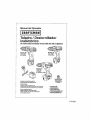
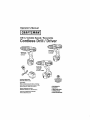
Operator's Manual
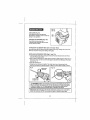
3/8-in. Variable
Speed / Reversible
Co
Drill/
river
Model No.
172.11834
12.0 Volt
Model No,
172.t1810
9.6 Volt
Model No,
172.67081
14.4 Volt
In Kit 9-11864
CHARGE BATTERY
BEFORE FIRST USE
CAUTION:
Read, understand and ;followall Salety
Rules and Operating Instructions in this
Manual before using Ihis product,
Sears, Roebuck and Co.
Hoffman Estates, IL 60179 U.S.A.
Visit our Craftsman ® website:
www.craftsmamcom
• WARRANTY
• SAFETY
• DESCRIPTION
• OPERATION
• MAINTENANCE
I
I
Warranty ......................................................................................
Salary SymbeL_ .......................................................................................
Page
Page
Salety Inslructions
Pages
.........................................................................................
f
f
I
f
I
2
3
4 - 10
Carton Contents ........................................................................................
Page
11
Description ............................................................. ...........................
Operalion .............................................................................................
Pages 12- 13
Pages 14 - 22
[
f
Maintenance ..............................................................................................................................
Pages 22 - 24
Accessories ........................................................................................................................ Pages 24 - 25
Repair Paris ...................................................................................................................................
Page
2_6- 31
I
Sea_s Repair Parts Phone Numbers ...............................................................................Back Cover
ONEYEAR
FULLWARRANTY
I
ON CRAFTSMAN_TOOL
II IhiS Craitsman tool tat!s due to a defect in mateflal or workmanship within one year from
the dale of purchase, RETURN rrTo ANY SEARS STORE OR OTHER CRAFTSMAN
OUTLET IN THE UNITED STATES FOR FREE REPLACEMENT,
This warranty
I
t
does not Include expendable parts such as lamps, batteries, bits or blades
II this Craftsman product is used for commercial
tot only 90 days from the date of purchase,
or renlal purposes,
this warranty applies
This warranty gives you specific legal rights, and you may also have other rights which
vary from state to state°
Sears. Roebuck
and Co,, Hoftman
Estales,
I
1
1
1
1
l
t
tL 60t 79
1
I
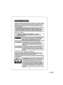
SAVE THESE INSTRUCTIONSt
READ ALL INSTRLICTIONSt
1
1
!
[Z_
WARNING:
Some
dust created
the Stale
of California
to cause
cancer
l
by using
power toots
contains
chemicalsharm.
known to !
and
berth defects
or other
reproductive
1
1
1
!
f
|
The purpose of safety symbols is to attract your attention 1opossible dangers_.
The safety symbols, and the explanations wi_hthem, deserve your careful
attention and understanding. The symbol warnings DO NOT by themselves
efimtnate any danger. The instructionsand warnings they give are no substitutes
for proper accident prevention measures..
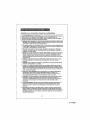
Z_ WARNING:
BE SURE to road and understand
all safety Instructions
in
this menus|, including all safety alert symbols such as "DANGER",
"WARNING"
and "CAUTION",
BEFORE using this drltlldriver. Failure to follow all instructions
sted below may result in electric
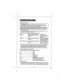
SYMBOL
shock, fire and/or
serious
personal
injury.
MEANING
SAFETY
ALERT SYMBOL: IndicatesDANGER,
WARNING,OR
CAUTION. May be used in conjunction with other symbols or plctographso
serious
Failure to
injury
obey tothis
yourself
safety orwarning
to others,
WILLAlways
result follow
in death
theor
safety precautions to reduce the risk of fire, electric shock
and personal injury.
t
Z_WARNING
[Z_
CAUTION
Failure to
obey tothis
safety orwarning
CANAlways
result follow
in death
!I serious
Injury
yourself
to others_
theor
safety precautions to reduce the risk of fire, electric shock
and personal Injury.
| Injury
Failure totoyourself
obey this
MAY damage.
result in
or safety
others warntng
or property
J
follow the safety precautions to reduce
electric shock and personal injury.
DAMAGE
PREVENTION
AND INFORMATION
personal
Always
the risk of fire,
MESSAGES
These inform usor o! Important
Information
andtor instructions that could lead to
equipment or other property damage if not fotlawed Each message Is preceded by the
word"NOTE:"
as In the example below:
NOTE: Equipment
are not followed.
WEAR YOUR
andlor
property damage
may result if these instructions
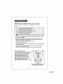
Z'_WARNING:
The operation of any drillldrlver
can
result In foreign objects being thrown into your eyes,
which can result In severe eye damage. Before beginning
power tool operation, ALWAYS wear safety goggles or
safety glasses with side shield and s full-face shletd
when needed. We recommend a Wide Vision Safety
Mask for use over eyeglasses
or standard safety glasses
with side shield, available at Sears Stores or other
Craftsman Outlets.
7-11-07
_
before using this drflltdriver.
I manual
_ WARNING:
BE SURE to read
tn electric shock, fire and/or serious
WORK
Failure to follow all instructions may result
and understand all instructions
in this
personal injury,
AREA SAFETY
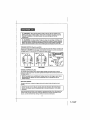
1_Keep your work area clean and well IlL Cluttered workbenches
invtte aecldenls,
arid dark areas
2+ DO NOT operate power tools in explosive atmospheres, such as tn the presence
of flammable liquids, gases, or dust+ Power tools create sparks which may Ignite
the dust or fumes°
3. Keep bystanders, children and visitors away while operating
Distractions can cause you to lose control+
4., Make your workshop chlldproof
away when not in use+
a power tool,
w+lh padlocks and master switches,
Lock toots
5- MAKE SURE the work area has ample lighting so you can see the work and that
there ere no obslructions thai will interfere with safe operation BEFORE using your
cordless drtll t driver.
PERSONAL
SAFETY
_o KNOW your cordless drill/driver,
Read the operalor's manual carefully Learn the tool's
appficalions and l+mftations, as well as the specific potenliat hazards related to this looL
2. STAY ALERT, watch what you are doing and use common sense when operating
a power tool
3. DO NOT use power tools while tired or under the influence of drugs, alcohol or
medication. A moment of inaltantion while operating power tools may resull in
serious personal injury
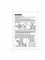
4, DRESS properly. DO NOT wear loose clothing or jewelry. Pult back fang hair, Keep
your hair, clothing, and gloves away from moving paris Loose clottliog, or long hair
can be caught in moving parts. Air vents often cover moving parts and should
also be avoided,,
5. AVOID ace+dental starting Be sure trigger switch is In the "Locked OFF" position
before inserting battery pack., DO NOT eamj tools with your finger on the trigger swtlch,,
Carrying tools with your finger on the trigger switch or Inserting the battery pack tn tools
that have the switch In the "FORWARD" OR "REVERSE" position Invttes accidents,
6+Do not overreach= Keep proper footing and balance at all times, Proper tooling
and balance enables better conlrol of the tool in unexpected situations,
7-ALWAYS
SECURE YOUR WORK. Use clamps or a vise to hold work when practical,,
It Is safer than uslng your hand and frees both hands to operale too]
8+ USE SAFETY EQUIPMENT. Always wear eye protection, Dual mask, n0n, skid safely
shoes, hard hat, or hearing protection must be used tar appropriate conditions
9_ DO NOT USE ON A LADDER or unstable support.
Stable footing on a sofid surface
enables belier control of the toot in unexpected situations.
TOOL USE AND CARE
SAFETY
Z_ WARNING:
BE SURE to read and understand all Instructions before
operating this dri!lldrIver. Failure to follow al! instructions listed below may result
in electric shock, fire and/or serious personal injury.
t. ALWAYS use clamps or other practical ways to secure and support the workplece
to a stable platform. Holding the work by hand or against your body ts unstable and
may feed to loss of control.
2 DO NOT force the tool Use the correct tool and accessory bit for your appt_catlono
The correct tool and bit will do the job better and safer at the rate for which it is designed,,
3_ DO NOT use the tool if trigger switch does not turn it "On" or "Off". Any tool that
cannot be controlled with the trigger switch is dangerous and must be repaired°
4. REMOVE the battery pack from the drill/driver
or place the forward/reverse
selector switch with power lock.off in the "Lock Off" position before making
any adjustments, changing accessories or storing the toot. Such preventive
safety measures reduce the risk o! starling the too{ accidenlaUy,,
5 STORE idle tools out of the reach of children and other untrained
Tools are dangerous tn the hands of untrained users,
6 ALWAYS remove battery pack and store separately
Is not being used.
persons,,
when drill/driver
7 When battery pack Is not In use, keep It away from other metal objects like:
paper clips, coins, keys, nails, screws, or other small metal objects that can
make a connection from one terminal to the other. Shelling the battery terminals
together may cause bums to skin, sparks or a fire,
8. MAINTAIN tools with care. Keep cutting tools such as twist drill bits sharp and
clean. Properly maintained tools with sharp cutting edges are less likely to b_nd and are
easier to use and control
9 CHECK for mteatignment
or binding of moving parts, breakage of parts, and any
olher condition that may affecl the tool's operatiom It damaged, have the fool serviced
bolero using., Many accidents are caused by poorfy maintained tools
10. USE ONLY accessories that are recommended
for this tool. Accessories that may
be suitable for one tool may become hazardous when used on another tool.,
Sea page 24 for accessories.
t t Keep the too! and its handle dry, clean and free from oil and grease. Always use
a clean cloth when cleaning. Never use brake fluids, gasoline, petroleum-based
products, or any strong solvents to clean your tool. Fol!owtng Ibis lute will reduce
the risk of !ass of centre! and deterioration o{ the plaslic enclosure el the drill / driver,,
7-11-07
ELECTRICAL
SAFETY
z_ WARNING:
BE SURE to read and understand
at1 Instructions
before
operating
this drllttddver_ Failure to follow all instructions
listed below
result in electric shock, fire andlor serious personal injury,
ruby
]
I
A battery operated toot with Integral batteries or a separate
battery pack must be
recharged only with the specified charging stand/transformer
for the battery. A
charger that may be suitable for one type of battery may create e risk of fire when
used with another battery,
t. Use battery operated toot only with specifically
any other batteries may create a risk of tire
2 Use battery
only wtth charging
MODEL
11810
9.6V
designated
standltransformer
battery
pack, Use of
listed,
CHARGING STAND/TRANSFORMER
BATTERY PACK
CDT109GU-103iBHY41q
140302001
CDTt 0£GU-t 04(ABP309GU),
1323405, 1323424 and
1301390 t 6
2.5V-200 mA,
11834120V
CDT112GU-!03/BHY41455V-200mA,
140302002
CDT112GU-104{ABP312GUt,
1322519,1322550,1322549,
1323412and130139017
67081 14AV (i_ kit118{;_)
CDTtt4GU-103!BHY41-18
140302003
CDT114GU4 04(ABP314GU).
!3t0714, 1322518, 1323407,
1323426 and 130139014
0V-200 mA,
3..Do not abuse the cord on the charging stand. Never carry the charging stand/transformer
by its power cord. Never pull the power cord to remove the transformer from the power
out[eL Damage to the cord or charging stand/transformer
could occur and create an
eleclric shock hazard. Keep cord away from heal, oil, sharp edges or moving part[;
Replace damaged cords Immediately Damaged cords increase the risk of electric shock
SAFETY
SYMBOLS
FOR YOUR
TOOL
symbols.
.....................................................................................
nO
current
cu_nl
Dim_
...............................................................................
.......................................................................................
The label on your loci may Include the following
V ........................................
.............................................
Volts
A ..................................................................................
.Amps
Hz.
Hertz
W.....................................................................................
Walls
rain ........................
.............................................................
Minutes
...........................................................................
Alternating
No-loadspeed
[] ..............................................................................
Class It conslruclion, Double lnsutaled
. Jmtn ............................................................................
Revolutions or Strokes per minute
.................................................................................
Indicales danger, warning or caution°
It means altentlonl Your safety is tnvofvedo
SERVICE
SAFETY
1 If any part of this cordless
drillldrlver
or charging
stand/transformer
Is missing
or should break, bend, or fail in any way; or should any component felt to perform
properly: have the missing, damaged or failed parts replaced BEFORE resuming operation
l
t
f
i
t
I
1
!
r
I
I
I
I
1
1
1
J
1
1
SERVICE
SAFETY conL
;2. Toot service must be pertormed only at a Sears Parts and Repair Center_ Service
or maintenance performedby unqualifiedpersonnelcould resultin s risk of tniury,
3, When servicing a toot, use only Identlcal replacement parts, Follow instructions
tn the maintenance section of this manual Use of unauthorizedparts or failureto
follow maintenance Instructionsmay create a risk ofefectdc shock or injury,
SPECIFIC
SAFETY RULES FOR CORDLESS
DRILL/DRIVERS
I _Know your cordless drlll/drlvero Read operator's
manual carefully_ Learn its
applications
and limitations,
as well as the specific potential hazards related
this toot. Following this rule wilt reduce the rlsk of electric shock, fire, or
serious Injury.
to
2 BE SURE that twist drill bits, screwdriver bits and other accessory attachments ere
properly and securely mounted in the chuck jaws BEFORE operating the drill / driver°
3..ALWAYS carefully inspect the material you are going to drtlt/ drive into. Drilling/driving
into nails, pipes and electrical wires can cause serious personal injury
4 HOLD DRI[.LI DRIVER by insulated gripping surfaces
(handles) when performing
an operation where the toot may drttl/ drive Into hidden wiring. Contact with a
"live" wire wLt! make the exposed me_al pads of lhe tool "tive" and shock the operator
5. NEVER hold the piece being drilled In your hands or across your togs.
It is impodant to support sad clamp the workpieoe properly in order to minimize
exposure, bit binding, or toss of control
6. Maintain
a firm grip on the drill/driver
lo resist stadtng
7. Use sharp accessory bile on_y. For drilling in WOOD
or power auger btts o For METAL use high*speed steel
use carbide-tipped
bits. For PLASTIC use Iow dd!ting
melting point, For SCREWDRIVtNG
use the proper
screwdrivlng
application such as Phillips, slotted
body
torque.
use twist drill bits, spade bits,
twist drill bits For MASONRY
speeds for maiedal wttha low
size screwdrtvtng
bit for the
and square recess bits.
8. BE SURE the material to be drilled is stationary, anchored or clamped firmly. If drilling
thin material, use a back.up block to prevent damage to the material,
1
1
1
l
t
i
i
!
9. ONLY USE the specifically designated battery
drill I driver and charging
stand/transformer.
create a risk of injury and f]rao
pack that was included with this
Use of any other battery packs may
10 Cordless tools do not have to be plugged Into an electrical outlet; therefore,
they are always in operating condition, Be aware of possible hazards when not
using your batter' t operated tool or when changing eccesaortes_ Following this
rule will reduce the risk of electric shock, fl_e, or serious personal intury
11 Do not place battery tools or their batteries
risk of explosion end possible injury
near fire or heat, This will reduce the
12, Do not crush, drop or damage battery pack. Never use a battery pack or charging
stand!transformer
that has been dropped or received a sharp blow. A damaged
battery peck is subjec! to explosion. Properly dispose of a dropped or damaged battery
pack immediately,,
l
t
7-11-07
SPECIFIC SAFETY
RULES FOR CORDLESS
DRILL/DRIVERS
conL
13 Batteries vent hydrogen gas and can explode in the presence of a soume of
ignition, such as a pt!ot flghL To reduce the risk of personal injury,neveruse any
cordless product in the presence of open flame An explodedbattery can propeldebris
and chemicals If exposed, flush with water immediately,,
'_4oDo not charge battery pack In a damp or wet location, Following this rule will
reduce the riskof electric shock,
15_For best results, yourbatlery pack shouldbe charged ine _ocationwhere the temperature
is more than 5g°F but less that SO=F,Donot store battery outside or in vehicles,,
16 Under extreme usage or temperature condftionst battery leakage may occur.
If liquid comes In contact with your skin, wash Immediately with soap and water,
then neutralize with lemon Juice or vinegan If liquid gets Into your eyes, flush
them with clean water for at least 10 minutes, then seek Immediate medical
attention Following this rule will reduce the risk of serious personal Injury.
17 Save these instructions. Refer to them frequently and use them to instructothers
who may use this tool If you toan someone this toot, loan them these instructions also
to prevent misuse of the preducl and possible injury,,
SAFETY
RULES
FOR
Z_ WARNING;
BATTERY
READAND
CHARGING
UNDERSTAND
follow al! Instructions
listed below may result
serious personal Injury.
STAND/TRANSFORMER
ALL INSTRUCTIONS.Failure
In electric
to
shock, fire and / or
NOTE: Before using battery charging stand/transformer,
read all Instructions
and cautionary markings In this manual, on battery charging stand/transformer,
battery pack, and drill / driver using battery pack to prevent misuse of the
products and possible Injury or damage.
!Ik CAUTION: USE ONLY the specifically designated battery charging
stand I transformer
that was supplied with this drill / driver when charging the
battery pack.The use of any other battery charging stand t transformer could
damage the battery pack, and create a hazardous condition.
Z_ CAUTION:To
reduce the risk of electric shock or damage to the battery
charging stand / transformer and battery pack, charge on_y the specifically
designated battery pack that was Included with thts drill / driver and the battery
charging stand / transformer, Charging other types of battery packs may cause
them to burst, causing personal [nlury and damage.
1 Donotusethebatterycharglngstandltransformeroutdoorsorexposetewetor
damp conditions° Water entering charging stand will Increase the risk of electric shock
;2 Use of an attachment with th_s batten/charging
stand I transformer
that Is not
recommended may result in a risk of tire, electric shock, or Injury to persons.
L-
SAFETY RULES FOR BATTERY CHARGING
STAND/TRANSFORMER
cont.
3 Do not abuse the cord on the battery chargfng stand ! tronsformer_ Never carry the
charging stand / transformer by its power cord,, Never pull the power cord to remove lhe
Iransformer from the power outlet. Damage to the cord or charging stand I transtormer could
occur and create an elsclrt¢ shock hazard Keep cord away from heat, oil, sharp edges or
moving parts Repiace damaged cords immediately Damaged cords increase the dsk of
electric shock.
4 Make sure cord is located so that it will not be stepped on, tripped over, come in
contsct with sharp edges or moving parts, heat, otl, or otherwise subjected to
damage or stress,, This will reduce Ihe risk of accidental fails, which could cause injury.
and damage to the cord which could result in electdc shock.,
5 Keep cord and charging stand / transformer away from heat to prevent damage
housing or Internal parts_
to
6. Do not let gasoline, oils, petroleum-based products, etc_ come In contact with
plastic parts. They conlain chemicals which can damage, weaken or destroy ptastic
7 An extension cord should not be used unless absolutely necessary, Use of improper
extension cord coutd result In a risk of fire and electric shock,, it an extension cord must be
used, make sure: a) Thai pins on plug of extension cord are the same number, size and
shape as those on the transformer, b) That extension cord is properly wired and in good
electrical condition, and c) That you use a proper extension cord. ONLY use cords
tiered by Underwriters Laboratories (UL} Other extension cords can cause a drop in line
voltage, resulting In a toss of power and overhealing of charging stand/transformer, An
AWG (American Wire Gauge) size of at least t4-gauge is recommended for an extension
cord of 25-it, or less in {englh Use 12.gauge for an exlension cord of 50-It
Extension cords lOg-it, or longer are not recommended.
8_ INSPECT tool cords for damage, De not operate charging stand with e dameged cord or
transformer, which could cause shorting and electric shock_ Have damaged Iool cords
repaired at a Sears Service Center
9, Do not operate charging stand I transformer if It has received a sharp blew, been dropped,
or otherwise damaged in any way.Take }t lo an authorized serviceman for electrical check to
determine tf the charging sland 1 iransfmmer is in good working order
10_Do not disassemble charging stand / transformer.Take
it to a Sears Parts end Repair
Center when service or repair is required. Incorrect reassembly may result in a risk of
electric shock or li_e,
1 t. Disconnect charging stand/transformer
from the power supply when not in us_.
This will reduce the risk of eleclrie shock or damage if metal items should tat! Inlo the opening In
the charging sland it else witl help prevent damage during a power surge
12 Risk of electric shock, Do not touch un*insufated porlien o! output conneclor or un-_nsulaled
batlery terminal,
13 Save these instructions.
Refer to them frequently and use them to instruct others who may
use this tool if you loan someone this tool. also lean them these inslructfons to prevent misuse
o! the product and possible injury
7-11-07
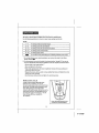
Z_ WARNING:
Some dust crested by using power tools contains chemicals
known to the State of California to cause cancer and birth defects or other
reproductive
harm,_ Some examples of those chemicals
are:
• Lead from lead-based paints
• Crystalline silica from bricks and cement and other masonry products,
• Arsenic and chromium, from chemically lreated lumbar_
Your risk from these exposures varies, depending upon how often you do
this type of work.To reduce your exposure to these chemicals:
• Work in a well-ventilated area
• Work wtlh approved so{ely equipment, such as those dIdst masks that are specially
designed to iiiier oul microscopic parlicles.,
Avoid prolonged contact with dust from power sanding, sawing, grinding,
drilling and other construction
activities.Wear
protective clothing and wash
exposed areas with soap and water. Allowing dust to get into your mouth, eyes, or
lay on the skin may promote absorption of harmful chemicals.,
Z_ WARNING:
Use of thts tool can generate andlor disburse dust, which
may cause serious and permanent respiratory or other injury. Always use
NIOSWOSHA approved respiratory protection appropriate for the dust exposure.
Direct particles away from face and body.
ADDITIONAL
RULES
FOR
SAFE
OPERATION
WARNING: BE SURE to read and understand all tnstructfons.
Failure to
follow all instructions
listed may result in electric shock, fire and/or serious
personal injury.
I, Know your drill/driver.
Read operator's
manual carefully,, Learn the applications
and limitations, as well as the speclljc potential hazards related to this 1ooiFollowing
this rule wit{ reduce the risk of electric shock. {ire or serious inJury_
2., ALWAYS wear safety glasses or eye shields when using this drill/driver.
Everyday eyeglasses have only impac{-reslslanl lenses; they are NOT safety glasses,
3 PROTECT
your lungs.Wear
a {ace mask or dust mask if the operation Is dusty.
4. PROTECT your heartng_ Wear appropriate personae hearing protection during use.
Under some conditions noise from this produc! may centrfbule to hearing lasso
5. SAVE THESE INSTRUCTIONS.
Refer to them frequently and use them to Instruct
others who may use this tool. If someone borrows
this tool, make sure they have
these Instructions
also.
10
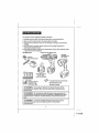
Thisproduct
hasbeen
shipped
compJetefy
assembled,
1_Carefully remove the Drill / Driver and Accessories from the Carrying Case,
2_,Make sure that all items listed in the packing list are tncluded_
3, lnspect the tool carelulty to make sure no breakage or damage occurred during
shipping,,
4_Do not discard the packing material until you have carefully inspected and
saUsfactodty operated the logic
5, I! any pads are missing, return to the nearest Sears store or other Craftsman outlet
to have the Drfll 1Driver replaced,
PACKING LIST:
Drill/Driver with Battery Pack
Worklight
(included ;n Kit
with 11864)
Extra Battery Pack
(in Kit 11834,
with 12,0 Volt Drill)
'_2
Double
Accessory Bit Sat
(included in Kit
11810 and 11834)
Ended Screwdriver
Bits
• Storage/Carrying Case
• Operator's Manual
_, WARNING:
If any parts are missing do not operate this tool until the
missing parts are replaced_Failure to do so could result in possible serEous
personal injury,,
Z_ WARNING:
Do not attempt to modify this tool or create accessories not
recommended for use with this tool,Any such alteration or modification is misuse
and could result in a hazardous condition leading to possibleserious personal
injury
Z_ WARNING:
To prevent accidental sfart|ng that could cause serious
personal injury, always remove the battery pack from the toot when
asserebltng parts,,
11
7-11-07
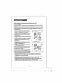
KNOW YOUR
CORDLESS
DRILL/DRIVER
(Fig.
1)
I features
OTE: Before
attemptin{]
and safety
rules. to use th}s product, familiarize yourself with all operating
i
Torque Adjustmenl Collar
Bubble Level
(( 11
JL.._
n LED
Swllch
wire
'2 Double Ended
Screwdriver B_ts
SIored on Tool
Ballery
Pack
Safety,paflormance and dependability have been given lop priority in the designof this product.
making il easyto maintain andoperate,,
Thla Cordless Drill/Driver
has the following
features:
I, Variable Speed allows you to malch drilIing/ driving speed Io bit and material used in a
variety of lob applications Increase pressure on trigger switch for higher speeds, decrease
pressure for !ower speeds,. Reverse to remove fasteners
2 Forward / Reverse
Power Lock-Off
Switch conveniently located for easy operation.
3.3t8-In_ Keyless Chuck hand tighlens bits fast and secure without chuck key Provides
positive retention o! ttl6*lnoto 3/B-In shanked bIls
4..23 Plus I Posltton Adjustable Torque Clutch adjusts lo automatically stop bit rotation a!
desired torque setting to prevenloverddving screws.. One lockedposition for drilling.
5 Electric Brake slops bit rotation tnstantfy when trigger is reteasado Idea; when driving
screws, nuts, and bolts.
12
_!
1
l
t
t
This Cordless DrtlllDriver
has the following features eonL:
6 Bubble Level helps provide accurate fight aegis drilling and driving straight into workplace.
7 ErgonomIc "T" Handle Design with molded in comfort grip provides maximum control
added balance and gripping comlort,
t
8 LED Light illuminates drtllt
t
I
J
1
J
l
J
i
i
I
I
drive area for hands free lighting
_nany applicali0n,
9 Fan-cooled motor provides the torque and power needed lot a vadet.y of drilling and
driving applications.
10 Durable impactweslstant
housing
he!ps protect toot from damage and reduces weight,
11 The N_ckeFCadmfum battery packs recharge |n 3 to 6 hours under normal use,
and LED light on charger lndicalas when battery Is charging,
12 Includes: 2 double_nded
and storage.
screwdriver
bits and Impact-resistant
case for easy carrying
13 The f 1810 - 9°6 Volt and 1 t834 o12.0 Volt Drill Drivers also Include a 24-pc, Bit Set,
!
t
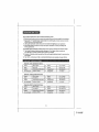
Mode} No, 11810 9,6 Volt Drill / Dtlver
l
l
!
t
I
I
l
l
I
Chuck
318 -in, ksyless
Cluleh
Ma_or
0.8 VoEIDC
To_quo
Switch
V_dable Spend/Flevnrs_bte
Charger
No Lo_d Sp_ed
O,600/mh_=,(RPM)
Charge Rate
3 - 6 Hour._
Model
12,0 Volt Drill I Driver
No, 11834
23 + I Position
Ml_. 85 In.,.tbt;.
Inpttt
•I2OV,5t3Hz AC
Chuck
3lS.tn_ keyloss
C]_dch
23 _ I Position
Motor
12+.0Vail DC
Tarqu_
ht_.x. 9S in..-_s.
Sw{tch
VatIabb SpOodfRevo_b|o
ChaftjerInput
I_OV,BDHz AC
NO Lor_d Sp_ed
O-61_t_Imir_,
(RPM)
Charg_
;3-S Hour'J
Rate
Mode} No. 67081 14,4 Volt Drill I Driver
Chuck
3,rS
4a.keylos_
C_tdch
23 ÷ I PosI|_r_
Motor
14,4 Val_ DC
T_rque
M,"_. 105 in.ol_n.
Sw_tch
Vn_int_,
Sp_',od
iRevar_ibie
Cha_'get Input
_'OV, 60Hz AC
No Load ape_
O.650rmir_,
(RPM)
Chargo Rat_
3--S Hr_urs
l
i
13
7-11-07
T
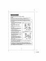
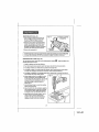
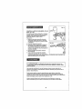
FORWARD / REVERSE
(Fig, 2, 2a, 2b)
Fig, 2
SELECTOR
SWITCH with POWER LOCK-OFF
Fig° 2a
FORWARD
Fig_ 2b
REVERSE
POWER LOCK-OFF
The direction of bit rotation is !orward or reverse and is controlted by a selector switch
Iocated above and to the rear of the trigger switch., When holding the dri|tlddver
in the
normal operating position, (and viewed from the back of the driiI!driver see Figs, 2, 2a
and 2b), the selector switch should be posilioned (pushed) a_l the way 1o the LEFT,
for FORWARD or normal drilling I driving, and positioned (pushed) all the way to the
RIGHT for REVERSE to remove ddll bits alld back out screws°
The third position for lhs selector switch is lccaled in the CENTER (Fig, 2b) This position keeps
lhe trigger swilch Item working, locking the power"OFF Selling the selector switch in the "OFF
or CENTER position helps reduce Ihe possibility of accidental starling when the tool is nol in use,
l
Z_ CAUTION:
complele
stop before
To prevent
changinggearthedamage,
directionekvays
of rotation.
altow
REMOVE BATTERY PACK FROM
DRILL / DRIVER (Fig, 3)
1, Place the Forward / Reverse Selector Switch
with Power Lock-Off into thecenter posttionto
lock the power off (see Fig,2, above),,
2 Locate the latches on each s_de of tile batlary
peck,,Depress (squeeze in) latches and pull
battery pack out o! drill,
14
the chuck
to come to a
]
,.-1
CHARGINGTHE
BATTERY PACK (Fig° 4 and 4a)
All Models
The battery pack lot this tool has been shipped in a low charge condilion to prevent
possible problems. Therefore, you should charge overnight prior to use..
Allow several cycles (operation followed by recharging}
for them to become
I NOTE:
Batteries wtll not reach full charge the first ttme they are charged.
fully charged.
1 Charge battery pack onfy with the charging
stand f transformer that was supplied wilh
this drill
/ driver.
Fig. 4
Transformer
2 Make sure power suppty is normal
household voltage. 120 volls, 60 Hz.
AC,onty,
3 Connect charging
power supply.
stand's transformer
Io
4 Place battery pack in charging stand., Align
raised rib on battery pack with groove In
charging stand (See Fig 4).
5, Press down on battery pack to be sure
contacls on battery pack engage properly
with contacts in charging stand,
6The charging stand has two (LED) indicator
lights, one green and one red
When a battery pack ls put into the charging
stand, the red LED wtll light,
indicating that the battery pack is charging
properly (see Fig 4a),
When the battery pack is charged and
removed Irom the charging stand, the red
light will go Off The green LED will come on
only when there is a problem with the
battery or charger,,
7 After normal use, 3 hours or less of charging
time ts required to fu]ty recharge battery
pack IIbattery pack iscompletely discharged,
required to fully recharge battery pack,
I
6 hours or longer of charging
time is
operate properly, or the charging stand does not charge the battery pack, return
the charging stand / transformer
and battery pack to your nearest Sears Store or
OTE: Within the warranty period, tf the charglng stand LED lights do not
other Craftsman outlet for free replacement°
15
7-11-07
CHARGINGTHE
BATTERY PACK conL (Fig. 4 and 4a)
B.The battery pack wift becomeslightiy warm to the touch while charging This is normal
anddoes not indicatea problem,
9. Do not place the battery chargingstand t transformer tn an area of extremeheat or cold,
it will work best at normal room temperalure.
10. When baitery pack becomes fuIly charged, unplug battery charging stand I lransformer
from powersupply and remove lhe battery pack.
L_ CAUTION:
If at any time during the charging
process the green LED
light ls iIlumtneted,
remove the battery pack tram the charging stand. Replace
the battery pack, and if the green LED light still comes on, take the charging
stand t transformer
In to be repaired / replaced.
L_ CAUTION:
If at any point during the charging process neither of the LEDs
are lit, remove the batter=/pack from the charging stand to avoid damaging the
producL Do not insert another battery,, Return the charging stand / translormer
and battery pack to your nearest service center for service or replacement.
CHARGING
A HOT
BATTERY
PACK
When using your tool continuously, the batteries in your batlery pack will become
You should let a hot battery pack coot down for approximately 30 minutes before
attempting to recharge-
hot
NOTE: A hot battery pack only occurs when prolonged continuous use of your drill/driver
causes the batterfes to became hot. It does net occur with typical use.Within the
warranty period, if the battery pack becomes hot with typical use, return the charging
stand/kansformer,
and battery pack to your nearest Sears store or other Craftsman outlet
for free replacemenL
INSTALLING
THE
BATTERY
PACK IN DRILL/DRIVER
(Fig. 5)
t. Place the Forward / Reverse Selector Swttch
wlth Power Lock-Off inlo the center posilion to
lock the power off,
2. Place lhe battery pack in the drill, aligning the
raised rib on battery pack with groove inside
the drill,
3 Make sure the latches on each side of the
battery pack "snap" into place, and the batlery
pack is secured tn the drill I driver before
beginning operation.
16
..... l
Ak CAUTION:
When placing battery pack in the tool, be sure raised rib on
battery pack aligns with the bottom of the drill and latches Into place properly.
Improper Installation of the battery pack can cause damage to internal
components.
WARNING: Cordless Battery Tools are always in operating condition when
the battery pack Is installed in the tool.Therefore
the Forward / Reverse Selector
Switch with Power Lock.Off should always be in the center position, locking
the
power off, when the tool is not In use or when you are carrying it at your side.
TRIGGER
SWITCH (Fig. 6, 6a and 6b)
To turn the drill ON, push the Forward/Reverse So{actor Switch with Power Lock-Off to lhe
FORWARD or REVERSE location (sea arrow direction embossed on swilch), and depress
the triggerswitch.To turn the drt!lOFF, release the trigger swttch_
FORWARD
VARIABLE
REVERSE
SPEED (Fig. 6b)
The variablespeed triggerswitchdelivershigher speed and torque with increased
pressureon the triggerswitch end lower speed and torque with decreased pressure on
the triggerswitch,
NOTE:You might hear a whistling or ringing noise from the trigger switch when
operating at low speeds° Do not be concerned; this ts e normal part of the
switch functiorto
ELECTRIC
1
|
/
BRAKE
To slop the drill/driver,
instantly,,
release the trigger switch and lhe eiectric brake will stop the chuck
NOTE: The drill/driver
will not operate unless the Forward / Reverse Selector
Switch with Power Lock"off is pushed fully to the left (forward) or to the rtght
(reverse).
Avoid running the drill/driver at low speeds for extended periods of time, Running al low
speeds under constant usage may cause the drt!_drtver to become overheated., ff this
occurs, cool ihe drill/driver
by running it without a Iced and at futi speed.
17
7-11-07
KEYLESS
CHUCK
(Fig.
7 and
7a)
The ddtltddver has a keyless chuck which allows you ]o bond lighten or loosen accessory
without the use of a chuck k-_y.
bits
1. Grasp and hold !he rear chuck collar wtih one hand (see Fig. 7),.
2. Rotate the front el the chuck with your other hand, clookwfse to CLOSE and
counterclockwise
to OPEN the chuck jaws (as viewed from the front of the chuck)
The front of lhe chuck also has embossed "pointing hands", Indicating whtch direction to
rotate the front of the chuck lo GRIP (tighten) or RELEASE (loosen) the accessory bits in
lhe chuck jaws (see F3g. 7a)..
Fig. 7a
COUNTERCLOCKWISE
(open'release")
Z_ WARNING:
Do not hold the chuck body with one hand and use the power of the
drill / driver to tighten the chuck Jaws on the accessory blloThe chuck body could slip in
your hand, or your hand could slip and come In contact with the rotating accessory bit.
This could cause an accident lresulttng In serious personal Injury.
23 PLUS 1 ADJUSTABLE
TORQUE
CLUTCH
(Fig.
8, 8a and 8b)
Thls drill/driver ts equipped wflh an adjustable clutch that has 24 different lorque settings. These
torque settings allow you 1oefficiently perform various drilling and screw driving applications,.
To adjust the clutch, hold the handle of the dri)lldriver with one hand and with the other hand
turn lha clulch collar to the left or rlgtll, and line the desired sel!ing (number or symbo!) up to
the embossed arrow on the top of the ddll/driver's motor housing (see Fig 8 and Be).
Fig. 6
fie CLOCKWISE
decreasetQrque}
Fig
us"
(to tncto,..setorque)
18
J "U
U
_
'l\,t
!
!
23 PLUS 1 ADJUSTABLE TORQUE CLUTCH (Fig. 8, 8a and 8b) cent.
Use the following guidelines to arrive at a proper torque settIng {see Fig,,8b),
Fig. 8b
1-4
For driving small screws
5-B
For driving screws Into soft material
9-12
For driving screws inlo soft and hard materials
13-16
17 -23
(least torque)
For driving screws In hard woods
For driving target screws
For normal to heavy twist ddlling into atl building materials
(most torque)
1. For normal drilling in wood, metal and ptasfics, turn and set the collar to the drilling
position symbol _i
2. For driving screws, turn and set the cellar to the desired setting t through 23 II you are net
sure of the appropriate selling using the guidelines in the chart (Fig. Bb), proceed as i'ollows:
,, Sat the collar to the lowest setting, "t"
=Dtive and tighten the first screw
• if the clutch ratchets before the screw ts tightened.
continue to tighten the screw.
Increase
the torque selling and
,' Repeat this process until you reach a torque setting that drives and ttghlens the screw
without the clutch raichelIng
,, Use that torque setting to drive and tighten the remaining
BUBBLE
LEVEL
screws,
(Flg_ 9)
In older to insure a pe_ect right angle when
drifltdriver inlo a werkpiece, you can use
the buill-tn bubble level on the top of the ddtlldriver
(see Fig.. 9). The bubbte torsi ts designed to work
when drilling/driving
In horizontal position..
Center theairbubble between the two lineson the
Level viewer as shown, and the drill!driver is in a
perpendicufar angle to the wo_kpiecs., This will
insure that you drill/driver etaeight into
lhe workpiece..
Center Atr Bubble between 2 tines
on Viewer for Horizontal drilling
19
7-11-07
L
I
Ftg.10
and 1Oa
LED LIGHT (Fig. 10)
Yourdrilltdriverhas an LED lightthat
illuminates the driltldrive area ior hands-free
lighlng in any application.,
ON-TOOL BIT STORAGE (Fig, 10a)
Your drillingI drivingcomes with
2 double ended screwdriverblls that store
on each side of the base_
24 PIECE
BIT ACCESSORY
SET (with
! t8t0
and 11834)
Your dritl comes with a 24 piece bit set thai is fitted into the carry I storage case Tl_is bil sol
allows you to pedorm many power drilting I driving jobs
INSTALLING
ACCESSORY
BITS (Flgs.11
and 11a)
t Lock the trigger switch Off by placlng the Forward/Reverse
Lock-Off in the Center position.
Selector Switch with Power
2. Open or close the chuck jaws to a point where the opening is slightly larger than lhe bit size you
intend to use .Atso. raise the trent of lhe driil slightly to keep the bff from falling out e! the chuck
jaws (see Fig. tl).
3 inserl the accessory
bit
4 Relate the chuck clockwise to tighten.. The chuck has an tcon of a hand next to the
word GRIP, pointing to the dtreclion lo grip, or tighten, the chuck jaws securely on lhe bit
Fig. 11
OPEN JAWS
'_
Flg_ 11 a
(Insert bit)
WARNING: Make sure to insert the accessory bit straight Into the chuck
Jaws. Do not Insert the accessory bit into the chuck Jaws at an angle then tighten,
as shown in Flgurs 11a. This could cause the bit to be thrown from the drill,
resulting in posstble serious personal in.fury or damage to the chuck.
NOTE: Rotate the chu_k body in the direction of the hand pointing next to word GRIP to
tighten the chuck jews° DO NOT use e wrench to tfghten or loosen the chuck jaws.
2O
1
REMOVING
BITS
(Fig. 12)
Fig,, 12.
I Lock the trigger swlich Off by placing the
Folward I Reverse Setec{or Switch wilh
Power Lock<}lf In lhe Center posllton.
2 Relate the chuck sleeve counterclockwise
._-m_-_,,.COUNTERCLOCKWISE
_'_
to open the chuck jaws,The chuck has an
icon of a pointing hand next to the word
RELEASE, showing the direction to release,
or loosen, the chuck Jaws around the btl.
,,=___
{Release BtI)
CLO '
3 Remove the accessory bit
NOTE:Rotatethe chuck body In the directionof thehand pofnt|ngnext to wordRELEASE
to loosenthe chuck jaws,DO NOTuse a wrenchto tightenor loosen chuckjews,
OPERATION
AS A DRILL
(Fig.
13)
Turn and set the torque clutch collar to the drilling position symbol_f_l,
desired drill bil into the chuck,
Instalf and tighten the
1. InslaI1 lhe battery pack into the drill/driver.
2, Push the forwardlreverse
selector swiIch with power lock,.off to the forward posilien,,
3 For dritiing in WOOD. use twisI drill bile. spade bits and auger bils.,
4.. For ddtling in METAL, use high speed twist drill bits., Use a coifing tubflcant when drilling
in melals, The exceptions are cast Iron and brass, which should be drilled dry,
5. For ddl]ing In MASONRY, use carbtde lipped bils or masonry bits.A smooth, even flow of
dust Indicates the proper dritiing speed,
6.Always apply pressure tna slraight line with
thebILIfnecessary,use thebubble levels
to dflII straight into the workpiece. Use enough
pressure to keep the bit biting, but do not
push hard enough to sta!t the motor or
deflect the bit,
7,,Hold drili/ddver flrrnly to control the twisting
action of the drill/driver,
B,,Move the ddtl bit into the workpiece, applying
only enough pressure to keep the bit cutting°
Do not force the ddllor apply side pressure
to elongale a hole, Lel the tool do the work.
9,When ddIting hard, smooth sudaees use a
center punch to mark the desired hole
ioeallon. This will preveP,t the drill btl from
si}pp_ng off-center as the hole ts started.
21
7-11-07
I
+
+
1
1
1
l
l
]
I
l
1
I
OPERATION
AS A DRILL
(Fig_ 13) cool
10. If lhe drilVdriver staffs, or the bit j_ms in lhe workpiece, it is _sually because the dril_/driver
is being overloaded RELEASE TRIGGER SWITCH IMMEDIATELY and remove bit from
werkptece Determine cause e! stalling+ DO NOT PRESS TRIGGER OFF AND ON IN AN
ATTEMPT TO START A STALLED DRILL/DRIVER
-THIS COULD DAMAGE THE
DRILL/DRIVER.
+
+
1 t Keep Ihe motor running when pulling the btt back out o! a drilled hole This will help prevent
jamming_
Z_ WA RNING:Be
prepared for binding at bit breakthrough. When these situations
occur, dr+lVdrlver has a tendency to grab and kick opposite to the direction of rotation
and could cause loss of control when breaking through materlaI_ If not prepared_ this
loss of conLrol ooukJ resul! in possible serious In)ury.
l
1
I
/
chuck stops turning Instantly° When the brake is functioning properly, sparks will be
NOTE:
This drllVdrtver
brake.This
When
the trigger
switch
is released,
the
/
visible through
the vent has
stets an
on electric
the housing,
is normal
and Is
the action
el the brake,
OPERATION
(Fig. 14)
AS A SCREWDRIVER
............
t
Turn and set the torque clulch eerier to the
desired torque setting, I through 2,3. Install
and tighten the desired fastener accessory
bit inlo the chuck.
1. tnstal_ the b_ttery pack into the drilltdriver+
2+ Push the lorwardtreverse
seloctor switch
to the forward posilion.
t
3+,Make a few practice runs, driving screws in
scrap material to make sure you have the
clutch so! at the proper torque setting for
your job.
4+When all adjustments are correct, drive
and tighten your fasteners.
5+.To remove fasteners, push forwardlreverso
!
l
I
1
selector swilch Io the reverse position+
l
l
I
_ WARNING:
servicing,
use only
identical
Craftsman
replacement
parts+
Use of soy When
other part
may create
a hazard
or cause
produot
damage.
I
t
!
i
shields when using compressed air to clean toots, tf the operation is dusty,
Z_ WARNING:
ALWAYSwear safety goggles or safety glasses with side
also
we_r a dust mask+
22
]
i
l
Z_ WARNING:
pack
from the toolTo
when
avoidcleaning
serious or
personal
performing
injury,
any
always
maintenance.
remove the battery
GENERAL
MAINTENANCE
Avoid using solvenls when cleaning plastic paris Most plaslics are susceptible to damage from
various types of commercial solvents and may be damaged by their use,. Use clean cloths to
remove dirt. dust. ell and grease, etc_
Z_ WARNING:
Do not at any time let brake fluids, gasoline, petroleum-based
products, penetrating oils, etc., come in contact wtth plastic parts_ Chemicals
can damage, weaken or destroy plastic which may result in serious personal
|n Jury.
CHUCK
REMOVAL
(Figs.
15, 15a and
15b)
The chuck may be removed and replaced by _ new one°
I
Lock the trigger switch by p_acing the Forward/Reverse
Lock-Oil in center, or OFF position,
2. Insert a 5tt6-in,
securely'
or larger he× key into the jaws of the chuck and tighten the chuck Iaws
3. Tap the hex key sharply with a mailer in a clockwise
loosen the screw in the chuck for easy removat
4
Selector Switch with Power
direction
(see Fig., 15)This
wilf
Open the chuck jaws End remove the hex key_
Using a screwdriver, remove the chuck screw
by lurning it in a clockwise direction (Fig. 15a)
Note that |he chuck screw has lelt hand threads
and clockwise direction loosens inslead of
tightens,
5, Insert the hex key back into the chuck and
tighten the chuck taws securely.,Tap sharply
with a mails! In a counterclockwise
direction
(see Fig t5b) This wiU loosen the chuck on
the spindle, tt can now be unscrewed by hand.,
Fig. 15b
Ffg.15a
23
J
7-1 1-07
Fig.16
TO RETIGHTEN
A LOOSE
(Figs. 16 and 16a)
CHUCK
The chuck may become toose on the spindle
and develop a wobble Also, the chuck
screw may become loose, causing tile chuck
Jaws to bind and pro#ant them from closing
TO lighten:
1. Lock the trigger switch by placing Ihe
Forward t Reverse Selector Switch with Power
Lock-Oil in the cenler, or OFF position,,
2 Open lhe chuck jaws,,
3 insert a 5116 in,, or larger hex key tnlo the
chuck and tighten the chuck jaws securely
Tap the hex key sharply wllh a mallet
in a clockwise direction .This will tighten
the chuck on lhe spindle.
4 Open the chuck jaws and remove the hex key,
5 Tighten the chuck screw, Nolo that lhe chuck
screw has left hand threads and
counlerclockwise
direction tightens instead
of loosens.,
WARNING:
recommended
tnJury_
The use of attachments
or accessories
for this tool might be dangerous
that ere not
Sears and olher Craltsman '_ outlets offera large selection of Craftsman
accessories designed for el; your drill !driving epplicalions,
You may purchase
kits and sels specilicalty
t
and could result in sedous
drit;/driver
for drilling and drivtng, twist drtfl bit sets,
a varietyof power drill l ddvlng bit sets, spade bit sets, carbide-tippedmasonry drtll bit sets,
exlra long bits° magnetic bi! holders and more,
Vist! your local Sears store or other Craftsman outfets or shop seam,,ccm/craftsman
of the accessories
for your drill/driver.,
24
for all
BATTERIES
The battery pack ior this toot is equipped with nickel-cadmium rechargeabte batteriesLength of service fromeach chargfng will depend on the typeof work you are dotng_
The batlertes In Ibis Iool have been designed to provide maximum trouble-free life,
However, like all batteries, they will eventually wear out. DO NOT disassemble
battery
pack and attempt to replace the batteries° Hand(Ing el Ihese batleries, especially when
w_aring rings and jewelry, could result in a serious burro
To ob(ain the longest posstb(e battery li(e, we suggest lhe following:
t.
Remove the battery pack from the charger once it is fully
charged and ready for use
For battery s(orage
longer than 30 days:
• Store the battery pack where the temperature
• Store ba!.tery packs _na"dfscharged_
Is below 80°F
condition
BATTERY PACK REMOVAL AND PREPARATION
FOR RECYCLING
To preserve natural resoumes, p(ease recycle or dispose of batteries pmperly_
This productcontains nickel.cadmium baIteries, Local stale or federal laws may prohibit
disposalof n(ckeFcadmiumbatteries in ordinary (rash
Consult your localwaste authority for information regardingavallab(e recycling and / or
disposal options,
Z_ WARNING:
Upon removal, cover the battery pack's terminals with
heevy-duty adhesive tape_ Do not attempt to destroy or disassemble
battery
peck or remove any of its components. Nickel-cadmium
batteries must be
recycled or disposed of properly. Also, never touch both terminals
with metal
objects and / or body parts as short cIrcutt may result. Keep eway from children.
Failure to comply with these warnings could result in fire and/or serious lnjury_
25
7-11-07
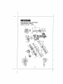
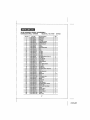
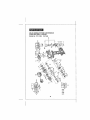
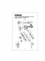
3/8-IN.VARIABLE SPEED/REVERSIBLE
CORDLESS DRILL / DRIVER
Model No. 172.11810
9.6Volt
/
26
t
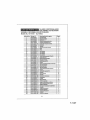
3t8-1N.VARIABLE SPEED/REVERSIBLE
CORDLESS DRILL 1DRIVER
Model No. 172J1810
Item No.
Part
Deecrlption
Q_.
CDT109GU-I
Bubble L_vel
1
2
CDTI09GU-2
Brand label
1
3
CDTt09GU-3
FiR button
4
CDTt09GU-.4
CDTt09GU-5
Driving 8it PH_IPH2
LetURigh_ Housing
Molar Switch ur_li
10t
CDTt09GU-t01
1
.................
!
1
1
6
CDTI09GU_6
Switch
1
7
CDTt0gGU-7
Terminal
1
3t
CDTI09GU-8
CDT10gGU*31
Power Supply goesd
Me,or
32
CDT109GU=32
Pinion
I
40
CDT109GU.,40
lnlerWlre
1
4I
CDT109GU.41
Inter Wire
1
42
43
g
CDT109GU-42
CDTI0gGU,A3
CDT10gGU-g
Inler Wife
1
Inter Wire
t
i0
CDT109GU-tO
12
CDTt09GU-12
13
COTI0gGU-t
3
D_sc Spring
Driving B}_.S?J6
Rsted Label
14 .......
15
CDTI09GU-t4
CDT109GU-t
Retaining Rtng12
1
5
Spring
t
t 6
CDTtOgGU-16
clulch
Salting, SleeVe
1
t 7
CDT10gGU-17
Clutch
Cap
1
t g
CDTI09GU-18
Disc Spring
t
CDT_09GU-Ig
CDTIOgGU-20
Beedng Cover
SelfTapplng Screw ST33x16
!
3
21
CDTI0gGU-21
Chuck
t
22
23
CDTI09GU-22
CDTtOgGU-23
Screw M5 La{t xl 6
Washer
1
2
24
25
...... CDTt0gGU-24
CDTt09GU-25
....... _g .........
20
.....
No,
I
5
.....
Paris
9.6 Volt
t02
CDTIOgGU-102
26 ......
CDTt09GU-26
27
2B
CDTf09GU-27
CDTf0gGU-28
29
CDT10gGU-29
30
CDTt09GU-30
33
CDT109GU-33
34
35
CDTt 09GU-34
CDT109GU-35
;36
CDT109GU-36
37
38
CDTI09GU-37
39
, 103
104
1
.............. i ....
Sail Topping Screw ST3,Sx'_8
CDTI09GU-38
CDT109GU-39
CDT100GL1_103
CDT109GLI.104
9
,
2 ............
1
I
t5
t
t
Fore Housing Asm
t
Fore Housing
1
Seating
12
Steal Ball 75
t
Ring Gear
1
Output Shall Set
4
SeJ!Tapping Screw ST3xt6
1
Adapter R_ng
2
Screw Washer Asm M3x8
1
Washer
3
Planetary/Gear l
Planet Carrier
t
PlanetaryGear I1
3
Chatter
..............................................
!................
Betlery Pack
1
Steal Bail ?3
Washer
27
7-11-07
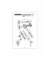
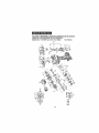
3!8-IN.VARIABLE SPEED / REVERSIBLE
CORDLESS DRILL/DRIVER
Model No, 172.11834
12.0Volt
2B
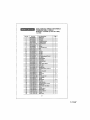
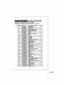
3/8-1N. VARIABLE SPEED / REVERSIB LE
CORDLESS DRILL / DRIVER
Model No. 172.11834
Item
No.
Parts
No=
Part Description
12.0 Volt
Qty.
t
CDTt09GU_1
Bubb_ Leve_'
I
2
CDTt09GU-2
Brand labe_
t
3
CDTt09GU-3
FiR button
t
4
CDT109GU-4
D_'ivtngBit PHtlPH2
I_
5
CDT112GU-5
LeWRight H0u,_ing
t
CDT112GU-t01
Motor Swfl_h unit
t
6
CDT109GU..6
Switch
t
7
CDT109GU-7
Terminal
t
B
3t
CDT112GU_
CDTl12GU-31
Power Supply Board
Motor
1
t
32
CDT109GU-32
Pinto_
I
40
CDT10t}GU,40
tnter Wire
I
4t
CDT109GU_I
_nt_rWIre
t
48
CDT109GU,,42
interWfro
t
43
CDT109GU.,,13
inter Wire
10t
g
,
cDTi09GU,.9
i
i
$_iiTeppfng$crewsT3_:i8
I
9
10
12
CDTIOgGU-10
CDT10gGU-t2
Disc Spring
DrMng Blt $2/6
2
t
13
CDTt
Rated Label
1
14
CDTIOgGU-14
RetChing Rtngt2
t
15
CDT10gGU-t5
Spdng
t
16
CDT109GU*t6
Ctulch Setting
17
CDT'I09GU-17
Ciutch Cap
t
1B
CDT109GU-t8
Disc Spring
1
19
CDT'_OgGU-t9
Bearing Cover
20
2t
CDTtOgGU-20
CDTt 09GU-21
SeIf Tapping Screw
Chuck
22
CDTtOgGu-22
Screw M5 Left X16
t
23
CDTt0gGU-23
Washer
2
84
CDTt
Steel Baii 73
t5
25
COTtOgGU-25
Washer
1
102
CDTIOgGU-_02
Fore Housing Asm
26
27
CDTi09GU:2B
FOre Housing
t
1
CDT109GU-27
CDTt09GU-28
Bearing
StoBf B_II ?5
t
28
29
CDTt09GU*29
Ring G_ar
1
30
33
CDTtO9GU-30
Output Short Sat
CDTtOgGU-33
SatlTapping
34
CDTtOgGU-84
35
CDT'tOgGU-35
Adapter Ring
Sc_ewWasher
36
CDTI09GU-36
Washer
I
37
CDTtOgGU-37
3
38
CDTt09GU*38
Planetary Gear l
P_anet Corrie_
39
103
104
CDTI09GU-39
Pbnetary
CDT!
CoTt
Chatter
Battery F_ck
12GU-t3
09GU-24
12GU_I03
i2GU,-i04
Sla_'B
t
t
ST3,5×'16
3
I
t2
Sclaw
t
$T3×16
,
Asm M3x8
Gear I!
4
t
2
I
3
1
t
29
7-11-07
3/8-1N. VARIABLE
I REVERSIBLE
CORDLESS
DRILLSPEED
t DRIVER
Model No. 172.67081 (in Kit 172.11864)
14,4 Volt
3D
3/8-IN.VARIABLE SPEED/REVERSIBLE
CORDLESS DRILL / DRIVER
Model No. 172.67081 (in Kit 172,11864)
14.4 Volt
Item
No,
......... i
2
,
Parts
No,
CDTt09GU-t
CDTIOBGU-2
CDT109GU-3
4
B
CDTt09GU-4.....I....
•
3
CDT!
10t
B
Part
""
.....
1
D'_iving Bit PHt/PR2
...............................
1
=lelt/Righl Housing
Mater Swilch unit
1
i
Sw_tch
1
1
7
CDT_09GU-7
Terminal
8
CDTt
Fewer
SUPPLY
aoer_
_4GU-8
3_ .... _,QTi
_4GU-3_
Meter
'1
32
CDTI09GU-32
Pinion
1
40
CDT10gGU'-4O
CDTi0gGU-41
Inter Wire
1
I
....................
4,!
Inlet Wtra
42
CDTIO_GU_,',,,, : , i_lerWl,e
43
CDT109GU-43
Inter Wira
C_D1;10BGU-g
So,!! Ta.pping Screw ST3,BxIB
9
.,
Qty.
.........t .........
..............................
i
FIR button
'"
14GU-5
,CDTt t4GU.,tO1
CDT1 D9GU-6
DescrlpUon
Bubble Level
Brand tabel
10
CDTt09GU_0
12
i3
CDTI09GU..12
CDTt 14GU-t3
i4
CDT't0gGULt4
.15
....................
Disc Spring
...............
Driving Bit S?J8
Rated L_bet
'
Relatning Ringt2
_B....CDT!09GU,IB
_.....................
I
.......
.......
CDTt09GU-15
................
...................................
9
'2 .........
1
1
1
Spring,
Clulch Setting Sleeve
1
t
Clutch Cap
t
Disc Spring
t
17
t8
CDTI
CDTt
t9
CDT10BGU-1B
Beadng
20
bDTi0gGU-20
21
COT'IOBGU-2't
S,el!Tappi,n,g Screw
Chuck
2.3
CbTt
Screw M5 Loll xlB
Washer
25
CDTIOBGU-25
Washer
1
102
CDT!09GU402
FO[_ HOUsing AFro i',,i',,'i",',ii,
.................
i
COT109GU-26
Fore Housing
........ 27
2B
CDT109GU-27
CDT109GU-28
Bearing
Steel Bait ?5
1
1
29
3O
CDTtOBGU-29
CDTI09GU-30
33
CDTt09GU-33
34
CDTY0_G_:_4
], A_,_!__i_
3S
CDT_O9GU-35
Sc_ewWasher
38
CDT109GU-36
Washer
37
CDT109GU-37
Planetary
3B
CDTI
0gGU-3B
......
,,l=_£e.!
C atrla
r
39
CDTI
0gGU-3g
Planetary
103
t04
CDT1 t4GU-1B3
Charg._r
t
CDTt
Batter/Pack
t
L..................
26
.... 2.
ogGu-u17
09GU-1B
09GUo23
.........
Covet
t
ST33x16
3 ...........
I
1
2
CD_i_,_'_" . Sioe_Bal,73 C,,I,'.........................
,5'
_4GU-104
...........
12
Ring Gear
....... Oulpul Shelf Sat
Self Tapping Screw
I
_:
S'i'3x'i8 ...........
4
1
Asm M3x8
2
1
Gear I
Gear I!
3
1
3
31
7-11-07
NOTES
32
Manual del Operador
Taladro / Destornillador
inaidrnbrico
de velocidad variable/reversible
de 3/8 pulgadas
Modelo No.
172.11834
12,0 Voltlos
Modelo No,
t72.67081
t4,4 Volt
En E! Kit 9-11864
Cirtlfled 1_ CA_UCSA
_ITD C22_ Nil _0745-L
CARGUE LA SATERiA ANTES
DE UTIL[ZAR POR PRIMERA VEZ
PRECAUCl6N:
Antes de utilizer ef producto, lea,
compranda y stga todas las Normas de seguridad
e lnstrucdones de funcionamiento
de este Manua_
Sears, Roebuck and Co.,
Hoffman Estates, IL 60179 EE.UU.
VFstta nuestro sitio web de Craftsman®:
www, craftsman.com
r_onform= f_=ttL 5TD
tt0745.t,rJ_7=l_.l,
Bg T45"_,,_
,2
•
•
°
°
°
GARANTIA
SEGURIDAD
DESCRIPCION
FUNCIONAMIENTO
MANTENIMIENTO
7-11-07
Garantla ......................................................................................
P&gina
34
Sfmbelos de Seguridad
P_gina
35
Instrucclones de Seguridad ...........
.........................................................................
Contendios delCart6n ..............................................................................
P_ginas
P_gfna
3B - 42
43
Descripcibn
..................
..............................................
P_ginas
44 _ 45
Funcienemlenlo
.................................................................................
Iviantenimtento .........................................................................................................
...................................................................................
P_ginas
P_ginas
46 - 54
54,56
Accesorios .......................................................................................................................
P&ginas 56 - 57
Rapuestos
P_gtnas 5B. 63
...................................................................................................................
NUn}eros de telOfono pare adquirtr repuestes Sears ................................................ Contrataps
UN AISle DE GARANTtA
COMPLETA
PARA ESTA HERRAMIENTA
CRAFTSMAN
=
St esta herramienta Craftsman falls debido aun defeclo en et materiat o mane de obra
den_ro da un ass a partir de la facha de compra, REGRI_SELO A LATIENDA
SEARS
MAS CERCANA
U OTRO PUNTO DE VENTA DE CRAFTSMAN
EN LOS ESTADOS
UNtDOS PARA REEMPLAZO
GRATtS,
Esta garantfa
no tncluye partes desechables tales come t_mpara_,
SIeste producto Craftsman se ullliza pare fines comerctales
splice solo pare 91) d;_asdesde ta fecha de compra.
Esta garanl[a le otorga derechos legates especificos
detaches, los cuales rattan de un estade a otto.
Sears. Roebuck
and Co., Holfman
plies, punla_ u hajas..
o de alquiler, esta garan_la
yes possible
que usted
longs otros
Eat.ares. IL 60179
IGUARDE ESTAS INSTRUCIONES1
tLEA TODAS LAS INSTRUCCtONESI
Z_ ADVERTENSIA:
Algun potvo generade per el usa de herramlentas el_ctdces
I
conttene qufmicos eonocidos per el estsdo de California per causer cancer y dsiectoa de
nBclmtento u otros defectos psra]a reproduccl6n,
34
El prop6sitode los sfmbolos de segufldades ]lamersu atencfSn con respeclo a losposfbles
petigros. Los simboles de seguridad y Ia explicaciSn de etlos merecen cuidadosa zztenclSn
y comprenst6n. La advertenc}a de los slmboiosNO eIimina ning,3npeffgroen sf. Las
instruccionesy advertenctas qua brindan no son sustiMas de fas medidas correclas de
prevenci6nde accidentes.
Z_ ADVERTENCIA:
ASEGt_RESEde leer y comprender redes las Instrucclones
de segurtdad de esfe manual, Inciusoroses los mmoolos de alerts tales come
"PELIGRO',"ADVERTENCIA" y "PRECAUCION", ANTES de utilizeresta herram[entao
S_no se respetantadss las Instrucclones que se Inoluyenen la stgulente lists oe
pueaen
pronttolr
aeacargas e=_ctrtcas,moendlos yto lealonea personales graves.
S|GNIFICADO
_
DE S|MBOLOS
iMBOLO DE
ALERTA DESe
SEGURIDAD:
ADVERTENCIA
O PRECAUCtONo
puede utilizer enIndiesPELIGRO,
conJuncl6n con afros
slmbolos o plctogralfaa.
SI no ae ireapote asia adverllencla de segurldad OCASIONARA _a
musrte o tesfones graves peroonales o en los dem6s, Slempre
alga las precauciones de segurtdad pars reductr el riesgo de
lncondtos, deseargas el_ctrtcas y teslones personales.
i OCASIONAR
II
la muerte
o leolones
graves personales
o de los
demos. Slempre alga las precauolones de segurtdad par n
Z_ADVERTENCIA raduclr
S! no sOelreapers
rlesgo osta
de incendios,
adverteneladescargas
de segurldad
el_ctricas
PODRA
y leslones
personales,
1LL'_
[ ._ PRECAUC|0N
PREVENCION
| ocaatonar lesiones graves persona_es o a los dem_i.s o da_os a
ta propledad. Stempre stga tas precaucianes de seguddad pars
] reduclr
Sl no se etraspers
rlesgo asia
de Incondtos,
advertoneiadescargas
de segurfdad
el_ctr]cas
ES POSIBLE
y leslones
personales.
DE DANES Y MENSAJES
DE INFORMACI(_No
Estos comunican al usuaflo la lnformaci6n ylo tnstrucciones lmportantos qua st no so
respeian, podr|an productr el da_o del equlpo o de otra propiedado Cads mensate es
preeedtdo per Iztpaiabra "NOTA:" come en el stgutente ejemplo:
y/o
NOTA,
Is pmp[odad.
St no se respetan estas Instrucclones
USE SUS
se puede productr el da5o del equlpo
Z_ ADVERTENC|A:
El funclenamfento
do cualquter mladro /
destornltlador
puede preductr que se lancen objetos extrafos
e los oJos, Io que puede pmduolr una Iest6n severs pare la
vista, Antes de Inlciar el funcionamlento
de la herramlenta
at_ctrtoa, SIEMPRE uflllee galas do segurfdad o anteojos de
seguridad con protecct6n lateral y un protector complete pars
ta cara cuando se_ necesarlo. Recomendarnoa una M_scara
_te segur|dad de vist'Sn amplta pars utilizer sabre los anteejos
o los anleoJos de eegur|dad est_ndar con protecct6n lateral,
_lspenlbtes on los Comerctos Sears u afros Puntos de vents
Craftsman.
35
7-11-07
_/_
|-,
p
L_ ADVERTENCtA: ASEGORESE de leer y entender lodes les tnstrucclones
de este manual antes de ut|lizar este taladro/destorn(llador.
Sf no se respetan
lodes las Instrucoiones,
se pueden produclr descargas eldctrloas,
Incendfos y/o
lestones personales
graves.
SEGURIDAD
DEL AREA
DE TRABAJO
1. Conserve el drea de trabaJo Ilmpia y b]en Ilumlnada. Los bancos de Irabajo
a_estados de objetos y las _,reas oscuras son una invItact_,n a los acctdentes
2- NO utitlce las herramientas
etdctricas
en embtentes explosives,
tales coma los
qua se encuentran en presencla de I{quldos Inflamables, gases o polvoo Las
herramienlas el_slricas hates chispaa qua pueden encender el polvo o los gases,
3, Mantenga e lee personas presentes, nlSos y vlsltantes alajados mlentras utlltza
la herramienta e!_ctrlca. Las distracctones pueden provocarle {a pdrdida del control,
4, Aseg',]rese de que el taller sea a prueba de nf_,os con candados e Lnterrupleres
gener_les.. Guards las herram}entas bajo |lave cuanda no sa ulilizan.,
5, Asegdrase qua el _rea de IrabaJo cuenta con amplia ilumlnect6n
pare _ue pueda
ver el lrabajo y qua no hays obslruco{enes
qua inlerferir&n con una operaciDn segura
ANTES de user su herramienla,
SEGURIDAD
PERSONAL
I, CONOZCA su talsdro / destornlllador
inal_mbdco. Lea cuidadosamenle
el menus{
da operaciones.Aprenda
Ias apticaclonea y fimllaclones de la herramienla, ast coma
tambi_n los pe_Igros potanciales espacificos reiaclonados con eL
2_ MANTENGASE
ALERTA, observe fo qua hace y utilice el senlido com_3ncuando utitice
una harramianla et_clricao
3. NO utifIce her_amientas elSe|fleas slesta cansado o bajo Influencla de drogas, alcohol
o alguna medtsaci6n. Un momenta de d{slraccl6n mtentras utilize herramientas
et_cldces puede provocar lasionas personeles gravas_,
4, UTILICE prendas de vasttr adecuadss. NO use ropa suefta nt aShaJas_Recoja at pelo
largo haole atr_s- Conserve el pete, lee prendes de rester y los guanfes aiejados de las
partes m6viles, Las prendas de vestlr sueltas o e! pelo largo pueden quedar
enganchados an lea parles mSvifes, Los conduclos de venltlaci6n generalmente eL=bran
tas parles m6viles y |arabian se deberfa evttar el conlac!o con atlas.
5. EVtTE qua se enclenda da manera acctdenlal, AsegQrese de que el inlerruptor de
gattllo se eneuentre en la poslci6n "BLOQUEADO"
antes de Inlroducir el cartucho de
batarlas. NO tleve herramientas con el dedo an el {nterruptor de gali{Io, Cuando Ileva
herram_entas con el dedoen el interrupter de gatil;o o introduce el cartucho de baterias
an }as herramientas qua t{enen el inlerruptor en la posici6n "AVANZAR' O
"RETROCEDER",
deIa la puerte ablerta a los accfdentes.
6, No plerda el equilibria.
Conserve y manienga el equilibria adecuadamenle
en lode
momenta,, Conserver y mantener el equilibria adscuadamenle permite un major control
de ]a herramlania en situactenes inesperadas
7,, SIEMPRE ASEGURE SU TRABAJO.
Util{ce abm._zaderss o usa morse pare sostener
cuando resul{e pr_clico. Es m_s seguro qua utilizer la mane y deja ambas manes
libres pare uil{izar la herramtenta.
8_ UTtLICE EL EQUIPO DE SEGURIDAD. Slempre utitiee protecei6n pare ia vista Se
deben utilizer m_scaras con|re el polvo, zapatos de aeguddad anttdesllzantes,
castes
o preleccl6n audifIva pare crear un ambfenie edecuado,
9., NO USAR LA HERRAMIENTA
SABRE UNA ESCALERA u otto apoyo Ineetable.,
Usa postcfbn eatable sabre una supedtcie s61ida psrmtla major control de la
herramienta en eltuactones tnesperadaso
36
I
SEGURIDAD EN LA UTILIZACI6N Y CU|DADO DE LA HERRAMIENTA
antes de utilizer este taladto
I destornillador.
qua se |ncluyen
en le slgulente
I tnstrucclones
_ ADVERTENC|A:
ASEGORESE
de leer
eldetricas,
tncendios
ylo teslones personales
SI no se respetan |odes |as
se pueden|odes
producir
descargas
ylists
eomprender
las Instrucclones
graves
1 S|EMPRE utiilce abrazaderas u aires formas pr_cticaa pare asegurar y ftJar ]a plaza
de trabajo a una plataforma estable. Si sosllena la plaza con la mane o con e] cuerpo,
no es as|able y puede pmvocar la pdrdida def control.
2
NO ap|fque presidn a la herramlentao Utlltce la herramtenta y fresa complemenlaria
corrects para su aplicact6n. La herramlenta y frees corrects realizar_n at trabajo major
y rods seguro ala veiocldad pare la cual se dise_6,
3
NO utlllce la herramlenta st et Interrupter de gatil|o no la"Apaga" o "Enctende"o
Cualqufer herremtenta qua no se pueda centre|at con el |n_erruptor de gatillo es
pe|lgrosa y se debe reparar_
4_ RETIRE el cartucl_o de be|arias del taladrol destornlliador o coloque el interrupter
selector de avanceJ re|recess con bloqueo en ta pos_et6n "bloqueeda" antes de
reattzsr cualqu]er ajuste, cambiar sccesorios o guarder la herramienta. Dlchas
medidas de segufidad preventives _educen el fiesgo de qua ta herramienla ss encientJa
acetdentalmente.
5 GUARDE las herramlentas qua no utilize fuera de! aleance de los nlSos y otras
personas lnexpertas. Las herram{entas son pellgrosas en manes de usuaries
inexpertos,
8, SIEMPRE saqt_e el eartuche de be|arias y gu_rdelo en un lugar separado cuando
el tsladm t destornillador no Be uttllza.
7 Cuando no se utilize el cartucho de baterfas, mant6ngalo eisjados de objetos de
metal coma: sujetsdores pare papeles, monedas, Ilaves. c!avos, torn|lies u aires
objetos de metal pequeSos qua pueden hacer una conexl6n de un term{hal al otroo
Hater un cortocircuito junlando los termtnales de balerla puede causer quemaduras en
ta piel, chtspas y/o }ncendios,
8. REALICE EL MANTENIMIENTO
de las herramlentas con cu[dado. Mantenga las
herramlentas, tales coma las fresaa helfcoidales aftladas y limp|as. Las
herramlentas conservadas adecuadamente con toe bordas de carte afllados tienen
manes probabilidad de atascarse y son m_s |_ciies de u_ilizar y contrelar,
g. VERIFIQUE el extsten desajustes o atascamienlos
de las partes m6viles, rupture
de par|as o cuetquter etra cend?ciSn qua pueda afectar el funcionamiento
de la
herramienta. St est_ daSads, lleve ;a herramienta a arregiar antes de ulilizar_, Muchos
accidentes son provoeados par las males condiciones de man|shim|ante de ]a
hertamlenta.,
10
UTILICE SOLAMENTE los accesorios
reeomendsdos
pare esta herramtenta° Los
accesodos qua pueden resultar apmpiados pare una herramienta pueden resullar
pellgrosos cuando se ul}lizan en arras herramientas_V_ase p_gina 56 pare vet los
accesoflos.
t 1. Mantenga la herramtenta y su mango secos, Ifmplos y ltbres de aceltes y grass.
Siampre ulilice un pal_o limpto cuando l|mpia. Nunca utilice |fqutdee pars freno.
gasoline, productos a base de petr,51eo o cualquier solvents fuerte pare [tmptar su
herramtenta_ Seguir esta nm-ma reducir_ el riesgo de perdida de contro_ y el deteriero
del pl_stico del gabinete.
37
7-I 1-07
f
t
t
SEGURIDAD
antes de utgizar este teladra/destorniIlador,
SI no se respeten lodes 1as InstruccIanes
sedepueden
produolr deseargas
el_ctricss
leer y comprender
todas las
Insirucclonss
tncendios ylo lesfonee personales graves.
se IncIuyen en in sIgulente
lists
I qua
Z_ ADVERTENCIA:
ASEGURESE
Una herramienta qua funciona a baterla con baterla integrsles oun carlucha de batertas
separado se debe recargar solamenle con el soportsi transformeder de carga espscificade
pare ia beleda. Un cargador qua puede ser apropiado pare un lips de bateria puede clear un
flesgo de trmeedto cusndo se uWiza con olra bateda1 Uliiice el taladro I dsstorntllador qua funciona a baleria ,3nicamenls con el carluche de
batedas de lists especIficamenie designadoo La ultlizact6n de cuatquier etm cartucho de
balerias puede crear un flesgo de incendio,
2 Uttfiee el carlucho de baterlas t_nicamenie con el soporte/translormador
de carga de Is lisl.a
especfficamente diseSado
CARTUCHODE BATERiAS
MODELO
SOPORTEDE CARGA]TRANSFORMADOR
11810 9.6V
CDTI09GU_!03/BHY41-12 5V_200mA
140302001
CDT109GU-104(ABP309GU),
132_3405,1323424 and 130139016
11834 12.0V
CDTI12GU-I031BHY41-I5
140302002
CDT112GU-104(ABP312GUL
1322519, 1322550, t322549,
1323412 an_ 130139017
67081 t4AV
[an_1t t864}
CDT!t4GUd031BHY41-IS.0V-200
140302003
5V-200 mA,
mA
DE SEGURIDAD
PARA
SU HERRAMIENTA
puede inelufr los slguIentes
simbolos:
YO_t_OS
........................................................................
V
Lo etlqueta de su berramlenta
t
1
1
1
_n_B
t
t
1
1
t
i
............................................................................
£0
.........................................................................
_1""
A ..........................................................................................
Ampefios
Hz ..........................................................................
Hercios
,Varies
rain ........................................................................
Minutos
aitema
__-=,=
...........................................................................
Cements continua
no ....................................................................................
',#eluctdad libra de cs_a
_J ....................................................................................
Construcci6n C_se tl, Dobleaishmlenlo
, Jmln ....................................................................
Revoluclones o Carfares par mln'_o
Indies psligre, advertencfa e precauci6n, Signifies:
iAtenct6nI Su seguridad se encuenlra compmmelida
...........................................................................
i
]
CDTl14GU-!04(AeF314GUL
1310714, 137.2510,1323407,
1323426 and 130139014
3 No abuse del cable del soporlel transformador de cstgao Nunca Ileve el sopotie/
tmnslormador de carga pot ef cable, Nunca tire de] cable pare sacsr el transformador de!
temacorflente, Si ss daha ef cable oet soportet transformadcr de carga se pueden productr o
craar peligros de descarga el_ctrlca. Manlenga el cable loam del alcance de fuer_les de calor,
acetic, bordes afilades o pallas mOvlles. Reempiace los cables dahades tnmedistamente Los
cables daSsdcs aumentan el rtesgo de descmgss ef_clflcas,
S{MBOLOS
1
1
1
1
t
i
ELECTRICA
SEGURIDAD
EN EL SERVICIO
{
TI_CNICO
1 St cuslquier parts de este talsdro / destornIIlador o del soportel translormador de
csrga se pierde, se romps, ee debts o falls de cualquier forms; o st ct_alquier
componente no lunclona sdecuadamente:
hags reemplazar la perle perdida, da_ada o
qua no funclons ANTES de utilizer nuevamente
38
t
L
SEGURtDAD
EN EL SERVIC|O
Tt_CNICO
cant.
2 El servlcfo t_cntco de la herramtenta se dabs reaitzar soiamente en un Centre de
repuestos y rsparaclones de Sears+ El servic+o [_cnlco o mantanimtanto qua so realiee
par parser|el no cal+ficado podria pmduc+r r+esgo de +es_ones
3 Cusndo realfae el sarvlclo t_cnico de una herramlents, utllica sotamenle las ptezas de
rapuesto td_ntiaas. Raspers lee Instrucctones
de la seccian de manlanlmiento
de esta
manual. S_ se utHizan pat|as no autodzadas o no se raspetan las tnstrucdones de
man|anita{asia, ss puede crear un riesgo de descm-ga ei_ctrica o Isaiah,
NORMAS
DE SEGURIDAD
DESTORNILLADORES
ESPECiFICAS
PARA
TALADROS
I
1 Conozcasutaladroldestorntlladorlnal_mbrlao.
Leacuidadosamenteetmanuaide
operaciones. Aprenda sus apltcac_ones y Ifmit_clones de la sierra, asf coma |arabian
los pelfgros potenclales eepecificos relacionados con esla herramlanta, SI reapers
esta regis, raduclr& los rleegoa de descargas elactfleas, tncendfos o leelones graves+
2. ASEGORESE de qua las frasas hellcoideles, fresas de destornillador y arras
accesorlos complementartae estdn bten montados an las mordazes del mandril
ANTES de utt!izar et taladro / destornltlador,.
3. {nspecciona cu{dadosaments SIEMPRE el malarial sabre el cual va a user el |atadm /
destorntllador. St uti{tzm el talaclro I destorni!lador en ctavos, tuber|as y cables el_ctrtcos
pueda provocat |aslones persenales graves,,
4o SOSTENGA ELTALADRO / DESTORNILLADOR
par |as superficies de empuP,adura
aisladas (mangos) cuando realize una operaclSn an la cue| |a herramtanta pueda
taiadmr / penetrar un cableado ocullo. El con|acre con un cable '_ivo" expondr_, las
par|as me{_licas a cordente y provocard una descarga en el usuar[o.
5.. NUNCA sostenga ta plez_ s teladrar con sue manes o entre sus plarnas. Es impartante
sostener y sujalar con abrazaderas la plaza de Irabajo adecuadamente alin de minimizar la
axpos+c+6n corporal el atascamtento de tas fresas o _ p_rdldade control
6 Sostenga f_rmementa ef ta{adm I dastornIIlador con ambas manes pars ras_stlr e_ par de
arranque.
7+ Ufllice |rases compIemanlar+as aI_ladas solamente. Pare taladrar MADERA utHice fresas
heticoidafes frees de pals o |rases pars readers de potenc{a. Pars METAL utilice {roses
halicoidaies de scare
.
pars atla veloeldad. Pars MAMPOSTERIA uttllce fresas ten punts de
carburo+Pars PLASTICO utilice vetccldadas de laladro baias pars material con punic de
|ustan bajo. Pars ATORNILLAR ull_ce fa {rosa de des|ors|lieder de tamaSo aproptado pare
Ia ap!+cacian del destorn{ltadar Isles coma fmsas phillips+de rarmm y de punts cuadmda.
8 ASEGORESEdequeelmaterialaserialadradopermanezca+nmbvil,
bien[ijoysujetocon
abrazaderaso 8t va a taiadrar material estrecho, utltice un b{oque de apoyo pare or|tar qua
se daSe el material
9 0NICAMENTE
UTILICE el cartueho de bater_as qua se tncluye con esta taladrol
destornlllador
y soporte 1 transformador
de cargm La utilfzaclOn da cuaiquter afro
cartueho de be|arias puede ctear un rlesgo de lasfSn e |neendlo.,
1(} Las herramlentas lnal&mbrfcas
no necesltan enchufarse
al tomacorr{ente; par la
taste, slempre ee encuentran an condtc_t_,nde funcionamiento,Tenge
presente los
poslblas pe|lgros cuando no se utilize la herramtenta que funciona con bateria o
cuando eatable los accesortos+ SI respeta esta regis+ reduclr_ los desgos de descargas
electrtcas+ tncendios o lesfones personates graves
11 No coloqua las herramianlas a be|erie o sus batarias cares del fuege odet taler. Esto
reducir_ el r+esgode exptosIones y poe+bias +esiones
I2 No aplaste, nl deJe cast, n| daP,e el cartucho de batarias, Nunca utlllce un cartucho de
bater_es o soportet transformador
de esrga qua ss ha cafdo o ha reetbido un golpe
fuerteo Usa hater,s daSada es susceptible a exptotar. Deseche adecuadamenle una
batefla qua sa ha caldo o daSado de masers tnmediata
3@
7-11-07
NORMAS
DE SEGURIDAD
ESPECiFICAS
DESTORNILLADORES
con|.
PARA
TALADROS
/
13. Las be|arias descargan gas de htdr6geno y pueden explorer en presencFa de aria
fuente de Ignlci6n, ta! coma una luz pilate, Pare reducir el desgo de lest6n personal
nunca at|lice ning_n product0 lnsl_mb_ice en presencla de llamas shier|as,. Una bateria qua
eslallapuede fanzar desechos y qu;rnlcos St quads expueslo, lave con ague tnmediatamente
14.. No eargue el cartucho de baterfas en un lager hi, merle o mojadoo St stgue esta
norms reducir_, el riesgo de desearg_, el_ctrica.
15., Pare oblener mejores resullados, se debe cargar el carlucho de bateflas en un tugar
en el cuaf la temperature sea mayor a 50=F pero menor que IO0_F, No guarde la
balerie a la tntamperie o on vehfculos,
16o Bajo condlclones
de usa o temperatura
extrema, se pueden produclr p_rdldas
on fa bater_a. SI el Ifquldo antra en contacto con su p|el, lave tnmedfatamente
con jab6n y agua, luego neutraltee
con _ugo do lim6n o vinegreo Si el Itqufdo
entre en eus alas , I_ve!os con agua tlmpla durante a! menoa 10 minutes,
luego
busque atenct6n m_dlca |nmedlatamente.
Si sigue esta norms reduelr_ el rlesgo
de lestones personeles graves.
17, Conserve estas lnstrueclones.
Remitase a elias t'_eeuentemente y utiltcelas pare
capacilar a ol[ras personas que puedan uliiizar esla herramienta. Si ie presta esla
herramfenta a alguna persona, pr_stele tambi_n estas lnstrucciones pare eviler et usa
inco_'recto
del produclo y pos_bleslesiones.
NORMAS
DE SEGURIDAD
CARGA
DE BATERIA
PARA
EL SOPORTE/TRANSFORMADOR
DE
Z_ ADVERTENCIA: LEAY
COMPRENDA
TODAS LAS !NSTRUCCIONES,
SI no
se respetan todas tas tnstrucctones
que se inciuyen en ta slguiente
Itsta se
pueden produclr descargas el_ctricas,
tncendios
y/o lestones personales
graves,
NOTA: Anf_es de utilizer el soporte / transformeder
de cerge de baterl_e, lea lodes
!as InstruccIones
y las marcas de precaucl6n
do este manual, on el soporte/
transformador
de cerga de la baterla, cartucho de baterlas y en el cartucho do
batertas qua utltiz_ el tatedro/destornlllador
pnra ev|tar el usa err6neo de los
produetos y postbies iestones o daises
Z_ PRECAUCION:
0NICAMENTE
UTILICE el soportef transformador
de carga
especiflcamente
disefiado
qua se sumlnistr6 con el taladro I destornillador
cuendo cargtm el eartucho de be|arias. E! usa de eualquter otto soporte I
transformador
de cerge podrls daSar et cartucho de bater_as y crear una
condlc|6n pettgrosa,
Z_ PRECAUCI{_N:
Pare recluclr el rfesgo de descarga el&ctrlca o daS_ al
soporte I transformador de carga y e! cartucho de baterfas, cargue _nieamente
con
el cartucho do balerfas Compsniones
specificamente
diseSado qua se |ncluye con
eate taladre I daatemflledor y soperte / transformader
de earga.Cerger
alto tlpo do
certuchcs do be|erie puede causer su exples|6n y provocar lesionea y dt_5os personal,
No uttltce et soporle ! trensformeder de carge en el exterior nt exponge e candle}ones
de humeded. St ingress ague on el soporte de carga aumenla_ et riesg0 do descarga
er_ctrfca_
2
La uttltzact6n de un accesorto no recomendado con este soporteJ transformador
carga puede produelr un rtesgo de lncendio, descarga elSe|flea o lesl6n e lee
persones,,
4O
de
NORMAS
DE SEGURIDAD
PARA
CARGA
DE BATER{A
cont.
EL SOPORTE/TRANSFORMADOR
DE
3 No abuse del cable del seporte de carga. Nunca lleve el soporte f t_ansformador de
carga per elcable Nunca tire del cable pare sacar el tcansformador del {omacontente. Si
sa defa el cable o el soporle I trans!ormador de carga se pueden pmducir o cmar peltgms
de descarga el,_cttfca Mantenga el cable fuem del alcance de fuanles de calor, aceite,
bordes alitados o partes m6vtles. Reemplace k_s cab{as daRados lnmed_alamente Los
cables dafiados aumentan el rtesgo de dasca_gas el_ctrlcas.
4 Aseg_rese de que el cable est_ ublcado de manors tel qua nadie la piss o se
trap[ace y qua no entre contacto can bodes ftlosas o partes m6vtles, calor_ acette o
qua sa somata de alguna otra forms a daP,o o tansJ6no Esto reduclr_, el rfesge de
caldas acctdenla{ee, qua podr{an causer lee{ones, y daSes at cable qua podr{an preducir
descargar e_ctricas
5 Mantenga el cable y aeperte / trans{ormador d8 carga alajados dat calor pare avttar
defies a fa carcase o partes Internaso
6 No de|e que ta gasoline, aceltes, productos a base de petr6leo, aloe entree an
contecto con las partea pt&st{cas.Contienen quimicos qua pueden da,3ar quttada
sotidez o desiruir el pl_sitco
7 No se debo utilizer un slsrgue a manes qua absolutamente neceaaHo. La uttfizaci6n
de un alargue lncorrec'te podrfa producir un riesga de tncendio y dascarga e{_ctrtca. SI se
debe utilizer un alargue, aseg_resa de: a) qua {as barnes del enchufe del alargua {engan
el mlsmo n_mero, tame_,o y forms qua los del J.rans{ormador del cargader, b) que ei
alargue se encuenlra conectado adecuadamenla yen buena condicf6n ei_ctrica y
c) utilizer un alargue adacuado. SOLAMENTE ulifice los cables incluidos en la lists de
Underwriters Laboratories (UL) Ot_os alargues pueden causar una ca{de en [a lines de
voltaje, to qua produce p_rdida de ene_gla y el sobrecalen_amlento del sopotte I
J.ransformador de carga. Se recomienda un tamaSo de Medida de cable americana (AWG,
per su sigla en {ngi_s) de calibre 14 al manes pare un alargue de 25 pies o manor Iongitud
Ulf{{ce un calibre '}2 pare un aia_gue de 50 pies No se recomiendan los atargues de 100
pies o de mayor fongttudo
B VERIFIQUE qua los cables de la herramIenta no est_n da_edos. No utltfce el soporte
de carga con un cable o trsnsformador de,ado, qua puede causer un carte circuffo
y descarga el_ctrlca. Liars _os cables da_'_edosde !e herramienl_ aun Cenlro da serviclo
t_cnico de Sears pare su reparaciSn.
9 No uttllce el soporle I trensformador de carga sf ha rec|btdo un golpe fuerte, se ha
caido o se ha da_ado do afguna airs manors. Lievelo aun t,_cnice aulorizado pare Ea
verificaci6n el_clrica pare determiner si e{ sopor_e / transformador de carga {un¢iona bien
10 No desarme el soporte ! transformador de cargm Ll_veto a Centre de repuestos y
reparaciones Sears cuendo se requlera e{ aarv_cto t_cntca o la reparacldm Si se
vueive a armar de manors Incorrecta pt,ede praductr un rlesge de deecarga el_clrica o
incendto
"_
_ Desconecta el soportel transl'ormador
de carga del sumlnlstro de energ{a cuando no
se encuentra en use. Es_e reducira el r{esga de dasca_ga et_ctrica o daScs an tes
articulos q_te caen an el orilicio dal soporle de carga Tambien ayudar_, a prevenir daSos
durance una sob_etensi_n
t2
Rfesgo de descarga el_ctrlca. No toque Is porcine no aislada de[ coneclor de as{ida ni el
terminal de ia bater[a no alslado.
13 Conserve estas instrucclones. Rem{tase a elias {recuen_emente y u_ll_celaspare
capacilar a et_as personas qua puedan u_ifizar esla herramien_a Si [e presta esta
herramienta e alguna persona, pr_s_ele iambl_n estas Instrucciones pare eviler el use
lncorrecto de! producto y posibles tesiones.
41
7-11-07
L_ ADVERTENCIA: AIgun pone generado per el use de herramlentas el_ctricas
conttene qulmlcos conoefdo per el eslado de Califernla per causer cancer y defectos
de nacimtento u aires defectos pare la reproducctbn_
Atgunos eJemplos de estos qutmtcos son:
'_Et ptomo de las pinturas a base de plomo,
• La silica cristaiina de toe _adrlHos, el ceman{o y otros pmd_clos de albahitefla
• El arsdnico y eI creme, de la readers lraiada quire+cements,,
El rlesge de estas expostelones
vails, dependlendo de la lrecuancia con que realize
eBte ripe de tmbaJo. Parr redt=cir eu exposlc!Sn a estoa qutmicoa;
•Trabaje en _reas b+enventiladas,
• TrabaJe con ]as equipos de segufldad aprobados+ tales come m_scaras centre el pelvo qua
est_n especialmenle diseRadas pare Iillrar parlic,Jlas microsc6picam
EviIe el contacts protongado con el polvo de liJadoras, sierras, pulidoras,
perferadoras el_ctricas y atlas actlvfdades de la construcei6n. UtilIce rope de
protecci6n y lave lea _reas expuestas con ague y |ab6n. SI permits qua el polvo
ingress a st= bees, ojos o parmanezca en la pfel, se puede fomenter ta absorci6n
de qulmlcos noclvos,
L_ ADVERTENCIA:
La utttizaci6n de esta herramienta puede genersr ylo
esparcir polvo, que puedB causal leslones respiratorias graves y permanentes o
de otra tlpo. Stempre uttltce la protecef6n resptratorta aprobada per el Institute
Nacionnl pare tv Segurtdad y Salud en elTrabaje/Departamento gubernamentsl de
los EE.UU. para la admlnistraet6n de la Seguridad y Salud en elTrabajo
(NIOSWOSHA, per sue slglas en Ingles) aproptada pare la exposlcldn al polvo,
D r J_las partrcu as fuels del a cance de la care y el cuerpo.
REGLAS
ADICIONALES
PARA
EL FUNCtONAMIENTO
SEGURO
L_ ADVERTENCIA:
ASEGIJRESE de leer y eomprender todas las
tnstrucctones. St no se respetan todas las lnstrucctones enumeradas
en la lists
se pueden producir descargas et_ctrloes,
Incendios y/o lesiones personales
graves,
1 ,, Conezoa su taladro / destorniltader.
Lea cuidadosamenle
el manual de operaclones
Aprenda tas apiicaciones y timilaciones, as( come tambl_n los peligros potenciales
especfl{cos relacionados con asia herramienta. S{ _espeta esta regis, +'educir& los
riesgos de descargas eI_ctricas, lncendios o lastones graves
2. SIEMPRE utlIfee galas de segurldad o protectores para la vista euendo emplee
este taladro I destornllIaclor,
Los anleojos pare lodes los dias solamente |ienen
fsntes reststsntes a Ios tmpactos; NO son galas de segurldad_
3,, PROTEJA sue pt=lmones. Utilice una mdscara pare ta care o una m_scara
potvo st el trabajo es polvarisnlo
centre e?
4, PROTEJA su nudtclSn° Utll+ce una protecci6n auditfva personal adecuada duranle el
empleo. Ba_o ciertas eondiciones, el rutdo de este producto puede contflbuir ala
p_rdida de la audictbn+
5. CONSERVE ESTAS INSTRUCCIONES,
Remflase a eIlasfrecuentemente
y utilicefas
pare capacltar a ntras personas qua puedan utilizer asia herramfenta, St alguien ta ptda
asia herramtenta prestada, aseg_rese de qua se Ileve lambi_n estas instrucciones.
42
I
I
I
I
I
Este producto so ha enviado completamente armado,
I, Saque con cu_dadola herramienta y los accesortos de la caja,,
2_ Aseg_mse de que todos los artfculos enumerados en la Ustade conlenidoo
3o Verifique la herramlenta cuidadosamente para asegurarse que no haya suCrtdo
roturas o da_os durante el envioo
4, No deseche el material de embalaJe hasta que hay termtnado de inspecclonar y
operar sattsfactorlamente ta herramtenta,
5, S! falta elguna parte, regrdsela al comercio Sears rods cercano u otros puntos de
venta Craftsman pare que le reempiacen e! Taladro t DeslorniUador.
LISTA DE CONTENIDO:
Taladro / Destornitlador con
cartucho de baterfas ! _n tafadro)
Luz de TrabaJo
(en el klt 11664 con
e[ tal_dro 67081)
Juego de Fresas
Accesortos
de 24 Pedazos
(11810 y 11834)
• Estuche de Almacenamlento/Transportadora
Manual de operaclones
se reempTacela parte que falta. SI no se hace esto podrIan ocurdr posib[es
_
ADVERTENCIA:
St falta aiguna parte, no utTticeesta herramlenta haste que
lesfones
personates graves°
recomendados
pare utilizer
con esta hertamiente,, Cualquier alteraei6n o modificaci6n
pmducfr una condtcibn peligrosa que puede
modificar esta herramtenta o crear accesorios no
conducir posibles |esiones personates graves°
considera use err_neo y podrta
[ so
_ADVERTENCIA:
No tntente
I
leslones personates graves, slempre saque el cartucho de baterfas de la
ADVERTENCIA:
Pare evltar
arranques accldentales
que poddan causer
herramlenta
cuando ensambla
las partes_,
43
7-11-07
CONOZCA
SU TALADRO
/DESTORNILLADOR
|NAL/_MBRICO
(Fig°
1)
NOTA: Antes de tntentar utilizer este preducto, famf_larEcese con redes lee
caracteristicas de funcionamlente y lee hermes de segurldad°
Abtazadera de sju_¢ede par
Nivel de burbuja
Luz LED
Luz LED
verde
Se ha dado m_xima prioddad a la seguridad, desempei_o y conftabitidad en el diseSo del este
producto, to qua facilila su manlenimiento y funcienamiento,
Esta tsladro I destornlliador
Ina!,_mbrlco liens lee slguientes
csracleristieas:
t, Velocldad variable se deja colncidir vetociadad de talsdrsndo y des[ornillando con fresa y
materist ussdo enuns variedad de applicactones de trabajoo Aumenia presi6n an ef gslilJo
de interrupter pare vetocidadss mas alia, disminua pmsi6n pare velocidades m_s baje
Dsmarcha air&s pare sacar.
2. Interrupter
selector ds avance/ retroceso con bisque de energ{a ublcado
convenientemente pars use I_cil,
3, Et mandril sin |lave de 3/B puIgade apriete ]as fresas per mane r_pide y seguro s_n ]lave_
Provea relenci6n positive de lresas de 1!1B a 3IB pulg,v_stago,
4 Embrague de torque sJusttbte 23 ÷ 1 poslctones a_usta pare detener aulomaticam_nte Is
rotaci(_a de fmsa ata poslci{_n deseada para impedir sobreatornillando de los families
Una pDstctdn fijada para talandro
44
Este taladro/destornlllador
5, Freno el_ctrlco
inal,imbrico
tiene las siguientes
deja rotacl6n de fresa tnstantz_neamsnte
6, Nivel de burbuja ayuda con proveer atornillando
p_'ecisoBEpteza de tTabajoo
caractarlsttcas:
cent,
al soltar eEgatil]o
en ,_ngu_orecto y ta_adrando recto y
7 Dlae_o de Mango "T" ergonemico con epu_adura suave moldeada
provea centrSI m_xtmo, mrs balanza y confort de agarre
B- Luz LED enc]endes el taladro I destorntllador
en cualqu_er aplicaciSn.
pare llum_naclen sin manes
9. Meter enfr]edo con vent|Tador provea torque y poder necesario pare una vadedad de
apticaclSnes de Ialandro y atornillando
10, Carcase durable,
de alto Impacto ayuda a protegef la herramienta
1'L Cartueho de baterias de n|quel,.eadmlo
de da_o, reduce el peso
recarga en 3 a 6 betas bajo el use normal
12, lncluye 2 fresas de destornillador de doble punta, y estuche de alto Impacto
pare tievando y atmacenamiando f&ctl,
13, Modelo 11810 - 9,6 volttoa y 11B34 - t2.0 voltios Tadadros I Destomilladores
lncluye Juego de Fresas Accesorlos de 24 Pedazos
Modelo
No.
tamb_an
118!0:
M_ndr|l
3;8 pule, s_ngave
Embrt_gue
23 + I Pc,,'_ic{_ne_
Motor
9,6 ",,tog_os
P_r
h';',},x./35potg.* I_b_s
interrupter
Va_cid_d vartab_o
Entt=tda de ¢arBedor
120V, 6OHz _C
Velocldad llbre de ¢erga
O-_0lJ/mte,
Indlco de €orga-
3 - 6 H_ms
Mandr[!
OJSpulg. sin flare
Embragua
23 + ! Po_ciot_es
M_tor
12,0 Vo_=os
Par
M_x. 95 pulg,-IIbmo
lnlerruptor
Va_cld_d vad_hle
ErttToda do cnr_ador
12eV, 60Hz .a.C
Voloold_d llbre d_ _area
O-6e0tmt_.
Jndlce da carg_
3 - 6 Hr_ms
Modolo
No. 11834:
Modelo No, 67081 en Kit 11864:
Mandril
3,_S
pulg.sinIlava |
Embr_goe
23 + '_Poslcier,os
Motor
t4,4 Vott_cs
Par
M_,
inlo:rrupt_r
Ve_cldadvarlab_,
Enlrada de c_rgador
12Or, 5OH_ AC
Veioc_dadlibra de cttrga
0-650,"rain.
Induce de csrga
3 - 6 Hems
!
t05 pulg..Ebras
45
7-11-07
INTERRUPTOFI
SELECTOR
DE AVANCE/RETFIOCESO
CON
BLOQUEO
DE
ENERGIA, (Fig. 2)
Ftgo2
Fig. 2b
Fig. 2a
AVANCE
RETROCESO
BLOQUEO
DE ENERG{A
La direcci6n de rotaci_n de {a fresa avanza o retrocede y se controls con el interrupter
selector qua se ubica en ta parts superior y posterior del interrupter de gattllo Cuando
sostfene el taladro f deslornillador
en }a posiciSn de |uncionamlenlo normal, (y visto desda
ef dorso det taladro t destornillador v_ase Fig 2 a, b, c), er interrupter selector se deberia
colocar (pulsar) comptetamente
hacia la IZQUIERDA, pare AVANZAR (b} o taladrar !
atornillar normaimente,
y colocar {pulsar) compfetamente hacia la DERECHA pare
RETROCEDER
(c} pare sacar |as frese de taladro o destorni]lar,
La tercera postci6n pare el Interrupter selector se ublca en et CENTRe (a).. Esta postci6n
p_evisne el functonamtento
dot interrupter de gatillo, to qua BLOQUEA Fa energla,. Colocar
el interruplor selector en la posici6n "APAGADO" o CENTRAL ayuda a reducir la_
peslbt{idad de arranques accidentates cuando no se utilize la herramienta.
Z_
PRECAUCI(SN:
Pare eviler
mandril
se detenga completamente
PARA _ETIRAR
EL CARTUCHO
BATERIAS
DELTALADRO
/
DESTORNILLADOR
(Fig. 3)
quaantes
sa dat_e
el engranaje,
siemprede deJe
qua B|
de csmbiar
]a direcctSn
la mtnei6n.
DE
1, Cotoque el Interrupter selector de avance 1
retroceso con bloqueo de energia en la
poslci_n central pare b]oquear la ensrgfa
(v_ase Fig. 2, ardba)o
2, Ubtque los seguros en cada lateral del
cartucho de baterles, Preslone (aprlete haole
adentro) los seguros y saque el cartucho de
baler{as del taladro..
46
PARA CARGAR EL CARTUCHO
Todos Los Modelos
DE BATER{AS (Fig° 4 y 4a)
Se envi6 et cartucho de bateflas pars esta he_ramtenta conuna csndtci6nde carga baja
pars evitar posiblesprobtemas, For Is tents, debeda cargada una neche antes de utilIzar_
Espere vartos cic[os (funcionamIento seguido de recarga) pars que se carguen
NOTA: La batedas no atcanzar,_nla carga complete 16primers vez que se cergan_
completamente,
1,,Cargue el caducho de batedas 0nicamente con
et seperte t traneformader de carga que se
suministra con el taladro I destorniliador.
2. AsegSrese de que el sumlntstro de energSa sea
voltaje dom_stfce normal, 12.0 voffies, 60 Hz,
CA 0nicamente.
3, Conecte el transrermader
suministro de energta,
del seporte
de carga al
4. Coloque el cartuche de bated'as en el soperte de
carga Alinee la osiris etevada del cartucho de
batedes con la ranura del ssporte de carga
(V_ase Fig,. 4)
5. Presione el cartucho de baterfas en el seporte
de carga asegur_ndoee
de que los conlactos se
enganchen adecuadamenle,
6. El soperte de carga tiene dee fucee Indicadoras
(LED), una roja y una verde.,
Cuando se enchufa ef transformador de soporte de
ca_'ga en un lemacorriente,
se prende el LED roja,
Io que lndtca que el cargader est_ Iuncionando
adecuadamente
(yea Fig 4a),
Cuando Cuando el cartucho de balerias se carga y
se sacs de! seporte de carga, se apagar_ la luz roja
La iuz LED verde se prende solemente ei hay una
problems con et cartucho de baledas o el cargader,
7 Luego del usa normal, se requferen 3 horse o mends de ttempo de carga pars
eargarcemptetemenle
el cartucho de balertas, Si se descarga completamsnte el
cartucho de baterlas, se requieren 6 hares o rods de tlempo de carga pars csrgar
comptetamente
el cartucho de bateflas
NOTA: Dentro del pertodo de tfempo de ta Gerant[a, si no funclonan
adecuadamente
las tucee LED del soporte de carga o el soporte de carga no
carga el eartueho de baterP_s, regrese la luz de trabajo at comerclo Sears o al
punts de vents de Craftsmen m_e cereana pars reemplezo gratis.
47
7-11-07
PARA
CARGAR
EL CARTUCHO
DE
BATERiAS conL (Fig° 4
y
4a)
8, E! eartucho de baterias ester& levemenla tibia al lacto mientras se cargo, Esto es
normal y no }ndica un problems.
9. No celoque el soporle / translormador
de cargo an un _rea de taler o Irfo exlremo
Funcionara meier a una temperature ambiente normal.
10, Cuando e[ carlucho de baterias se cargo completamente,
desenchufe el soporle/
lransformador
de carga del sumtnistro de energ{a y saque el cartucho de la baterla,,
Z_ PRECAUCt(_N:
Duranla el cargar, sl Is luz verde LED se lUumlne, sacs el
cartucho de bater{as del soporta de carga. Reemplaza el cartucho de baterfas
con otto, y si illumine abe la luz verde LED, regrese el soporte de cargo y
translormador
al Centre de Serv[cto Sears mrs cercano pare reparaci6n o
reemplazo.
/Ik PRECAUCION:
Durante el c_rgar, sl ntnguna luz LED se ftlumlna, sacs el
csrtucho de batertss del soporle
de cargo pars evttar ds_o at produclo_ NO
reemplsza
con elm cartucho de balerias.
Regrese et soporte de cargo,
transformador,
y cartucho de baler[as a| Centre de Servlcio Sears mrs earcano
psra reparectbn o reemptazo.
PARA
CARGAR
UN CARTUCHO
DE BATER[AS
CALIENTE
Cuando utiiiza su herramienta continuamente,
los balerias del cartucho de baterlas se
calentar_n
Debe dejar entdar un car|ueho de batertas cat|ante durante aproxfmadamen_e
30 m_nutos antes de tnlentar recargar.
NOTA:Uncarluchode bater_ascBltantesefamenteocurrecuandoel use continuede su
taladm / destornfUador
cause qualos baterlasse calinetemNoocurrenbaje cimunstanctas
normales..Remttasea "Pare cargarel cartuejo de baterfas"perale recarga normssde
baterms.SI el seporte del,csrgano cargo su cartuche de betsdasbsje circunstanc[as
nermales regresslame e, cartucnode balerlascome el seporte / translormedorde cergs
al comercioSears o el puntsde vents de Crattsmanm_s ¢ercano pare su reposlc 6n gratis.
PARA tNSTALAR EL CARTUCHO DE
BATERiAS EN ELTALADRO /
DESTORNILLADOR
(Fig. 5)
1,, Coloque et Interruplor setector de avance /
ratroceso
canbioqueode energlaen la
posIctSncentralpars btoquear fa energia,,
2o Coloque el cartucho de balerlas an el taladrm
Alines la estr|a elevadade[cartucho de
bateflas con la ranumdentro del taladm,
3.. Aseg_tresede qua los seguros en cads lateral
del cartuchode bateflas =encaje"
complelamentey de qua se sujets el cartucho
de batertas al laladro f destornIlfador antes de
comenza_s uti[izaro
4B
Z_ PRECAUCION:
Cuando coloque el cartucho de baterias en la herramlenta,
asegt_rese de qua la estrfa elevada del cartucho de baterfas se encuentre
alineada con la parts interior del taladro y los seguroa en su lugar de manera
sdecuada.
Ls fnstalaclSn
Incorrecta del cartucho de batarfas puede causer
daSoss los compensates
Internes.
L_ ADVERTENSIA:
Las herram_entas de bateria inelambdea slempre se
encuentran en condlclones de funcTonsmlento
cuando el cartucho de baterias
se tnstala en la herramienta. Par 1o tanto, el Interrupter
selector de avarice /
retreeeso con bloqueo de energfa slempre se debe encontrar en Is posicldn
central pare bloquear ia energfa cuando la herremlenta no est_ en usa o cuande
la lleva al lade suyo_
NTERRUPTOR
DE GATILLO
(Fig. 6 y 6a)
Pare ENGENDER et taladro presione ei Interrupter selector de avance t _eiroceso con
hroqueo de energfa a fa ubtcaci6n AVANCE o RIETROCESO (v_ase direccid_n de !s flecha
an relieve del inlerruptof) y apriete el interrupter de gatilIo Pare APAGAR el laladro suelle
ei interrupter del gatiltm
Figo6b
AVANCE
VELOCIDADVARIABLE
RETROCESO
(Fig
6b)
El interrupter de gatillo de ve{ocidad variable entrega velocidady
par m_s altos can un
aumento de la presiSn en el interrupter de gatitto y velocidad rods baJa con la disminuci6n
de tapresI6n an el interruplor
de gatIIlo,
Interrupter
de gatIIlo cuando Io utillza a vetocidades
bajas No se preocupe; esto
I NOTA:
probable
de sIibido o zumbido qua proviene de'
esuna Ea
parts
normal que
de escuche
la funcl6n undelruido
interrupter.
FRENO
1
ELECTRICO
i
Para detener el Ialedto / destorniilado_', suelle et inte_'ruptor de galillo y el fmno el,_cl_co delendr_
el mandrilIn$1ant_neamenle,
Inlerrupter
selector
de avance a /menoa
retroceso
blequeo
I completamente
NOTA: El Ialadro el
I destornillador
no funclonar_
qua con
se pulse
energis hecta la fzquferda (avance) o hacta la derecha (retrocesa)
de
J
I
Evite hacer funcloner el Iatadro / destomill_dor a velocidades bajas durante periodos de
tiempo pl'olongades. S_ hace funcioner a velocidades bajas bajo usa conslante puede
causers e| sobrecalentsrnienlo
det faladrO t deslornil!edor.
Siesto ocurre, enfde el
taladro t destomiIl_dor haci_ndoIo functener Iib_rede carga y a pleas velocidad,
4@
7-11 07
MANDRIL
SIN LLAVE (Fig. 7 and 7a)
El latadto t destomfllador liene one mandril sin llave que le permits ajuslar
manualmenle las {resas sin el use de una Ilave de mandril
o a!]ejar
1 Agarre y sostenga l`aabrazadera posterior del mandril con una mane (v6ase Fig, 7).
2 Gire la parts finn|!! del mandril con la otra mane, en el' sent_do de lab agulas dot reloJ
(segt3n se visualize desde el frente del mandril) pare CERRAR y centre el senttda
de Gas agujas del relo| pare ABRIR.
El frenle del mandril tambien liens manilos estampada en relieve indicando ]a direcci6n
gtrar al frente dot mandril pare SUJETAR (carter) o SOLTAR {abdr) ;as fresas accesorlas
de tas mDfdazes del mandril. (see Fig. 7a).
F} M 7a
_"
centre SenlldoDeAgu as
De1Relo)at,
dr "Solmt"
Z_, ADVERTENSIA:
No sostenga e! cuerpo del mandril con une man{) y utfllce Is
energ[a det taladre / destorntlfader pare ejuster les merdazas del mandril an la fresa
cempiementerta, Se podriD deslizar el euerpo del mandril en sue manes o su mane
pedals deslfz_rse enlrar en ¢entscle con Is fmsa cemp}ementerla gtraterla. Esto pedrle
causer un accidents leslenes y produclr les|ones personales graves.
EMBRAGUE
DE PAR AJUSTABLE
23 MAS
1 (Fig.
B, Ba y 8b)
Este taladro t destorntflador est,i equipado con un embrague aJustable que liens 24
configuracionas de par difarentes. Esias connguraciones de par le permilen realizer
eficlentemente varies apticaciones de taladro y a uste de tornillos., Pare ajustar el embrague,
sosienga el mango del latadro / destornlllador con una mane y con la olra gire la abrazadera
del mandril hacia la izquierda o derecha (v_ase Fig, 8) y atinee la configuracibn deseada
(numezo o simbolo) haste fa flocha en relieve en |a parle superior de la carcase del motor dal
taladro I destornillador {v_ase Fig. 8a).
i
Fig. 8
5O
EMBRAGUE
DEPAR
AJUSTABLE
23M_,S
1(Ftg_
8,8ay8b)cent,
Ulilice fas siguienles pautas para llegar a une configumci6n de par apropiada,
Fig. 8b
1 -4
Pare ajuslar families peque5os
5 *8
Para ajuslar families en material brenda
9 - 12
Pare ajustar families en materials
bfandos y duros
13 - t6
Pare ajustar tornilles
en maderas duras
17 -23
Pare ajustar lemillos
m6s grandee
,_
1.
(par manor)
Pare el taladro helicoidal narmat a pesado en materials de const_ucci6n(par mayer)
Pare taladrar en madera,
de poslci6n de taladro_
metal y p{6stico, gim y configure
la abrazadera
en el s|mbolo
2, Pare ajustar tornillos, gire y cenfigure la abrazadera en fa configuraei6n de I a ?..3
deseada, Si no est_ seguro de ta conftguracI6n aproptada utillzando las pautas de la
tabla (Fig_ 8b), precede de la sfguiente manera:
• Configure
la abrazadera
en la configuraci6n
m&s baja. "1"
• Atorntlle y ajuste el primer tornfIlo
• St e{ embrague atasca antes de que sa ajuste el tornitlo, aumente
par y conUntJe ajustando_
• Repifa este proceso haste Uegar ala configuraci6n
tornillo sin que el embrague se atasque.
del par que atomilla y ajusta el
° Ufifice esa cenfiguraci6n de par pare a_ornilfar y ajustar los tornillos
NtVEL
DE BURBUJA
(FIG.
la configuraci6n dei
restantes,
9)
A tin de asegurar un dngulo recto perfecto cuando
se taladre/atornt]la en una pteza de trabaja, puede
utilizer el nIvel de burbuja ubicado enclma del
Lafadre f destorniitador (yea Fig. 9), El nivel de
burbuja esta disefiado lrabajar cuando sa
taladra I afornitla ya sea en peslcl6nhoflzonlal.
Alinease ata burbtJja entre los des lineae, y el
taladro t destornilIador esta en ttn 6ngulo recto a
ia pieza de trabajo,, Esto a_egurara qua
ta_adre / atornille en l{nea recta a Ia pieza de t_'abajo
Al_nease _ burbufa de atre entre las
dos ltneas pets tatsdre horizontal,
51
7-11-07
Fig+ 1D
LA LUZ LED
(Fig. 10)
Su taladro I destornIifador liens une luz LED que
enciende el ;_rea de laladr_r / deslorniltar pare la
luz sin mane en cualqu}er aplicaci6n_
ALMACENAMIENTO
DE FRESAS
EN
HERRAMIENTO
(Fig° 10a)
Su taladro / destornfllader viene con 2 lresas de
destorni!lador con doble punts almacenado en
cads tado del base de het'ramionta.
JUEGO
DE FRESAS
ACCESORIOS
AlmacsnarniBnto DB Fresas
En H_rramtenlo
DE 24 PEDAZOS
(con
11B10 y 11834)
Su taladro t destorn+llador vtene con un Juego de 24 pedazos de lresas accesorios que
coloque on esiuche de aiamcenamiento
I transpertadoreo iSste Juege se deja desempeSar
muchos trabajes de letandro y destornlllando mec_nlco,
PARA
INSTALAR
LAS
FRESAS
COMPLEMENTAS
(Figs. 11
y
11a)
t,+ Bloquee el Interrupto_ de gatitlo colscando el Interrupter seleclor de avance I retmceso
con bloqueo de energfa en ta posici6n ¢enlral
2+ Abra o cierre Ins rnordazas del mandril haste un punlo on e! cual la abertura es levernente
mayor que el lamaSo de !a frees que intenla et;lizar,, Tambt_n, levante el frenle det taladto
levemenle pare evttar qua fa frees se salga de las mordazas del mandril
(v6ase Fig° t 1),
3, fntreduzoa la kosa oomplemenla.,
4,, Gire el mandril en el senltdo do Ins aguias del reloi pare ajuslar (SUJETAR) ins mordazas
dei mandril blen en ta ffesa. El mandd! ttene un mane en relieve al [ado de la palabra
GRIP, punlando ale direcciSn pare suietar,
Flgo 11
ABRA LAS MORDAZAS
(introduclr
Fig, t la
INCa RRECTO
CIERRE LAS MORDAZAS
(pare ajuslar ta lmsa)
L_ ADVERTENCIA:
Asegr_rese de introduclr la frees complementaria
en lines
rectB en les mordezes del mandril, No lntroduzca la Iresa complementarfa
en lee
mordazas del mandril aun _ngulo y luego ajuste, seg_n se muostro en la Figure
11a. Esto podrta causer que la fresa sea arrojada del ta|adro y producir posibles
teslones pereoneles graves o daSo al mandril,
NOTA_ Gfre el euerpo del mandril en la dlreoo;6n que sefiala fa mane con ta
mares GRIP (SUJETAR)
pera a]ustar Ins mordazes del mandril, NO utittce una
llave pare aJustar o aflojar leo mordazas del mandril,
52
l
I
I
I
Fig, 12
PARA
SACAR
LAS FRESAS
EN EL SENTIDO
{Fig. 12)
1 Bt_quee el interruplor de gatillo co{ocando
el Interruplor selector de avance ! _'etroceso
con b]oqueo de energ{a en ia posici6n
cenlral
2 Gira el cuerpo del manddt en senlido de Ias
las agujas del reloj pare abrir _s mordazas
El mandril tiene un mane estampado en
relieve at lade de la palsbra RELEASE
(SOLTAR}. mostrando la direcciSn de
aflojar las mordazas en ta freea
3, Saqueta lresa complementar_a.
RELEASE pare afloJar las mordazas dal mandril. NO UTILICE una liave pare ajustar o
NOTA:
el cuerpo del
del mandril.
mandril en la dtreec]6n qua seSala la mane con la marca
aflaJar Glre
lee mordazas
FUNCIONAMIENTO
COMa
TALADRO
(Fig.
l
14)
GIm y conltgure la abrazadera de{ mandril de per hacia e] simbolo
Instaie y ajuste la tresa pare talad_'odeseada an el manddL
t ,,lns_ale el cart_.=chode bater_as en el tatadro / destornillado_-
'_
de posici6n de laladro.
2., Empuje e! interrupter ee]_ctor de avancel _troceso con btoqueo en is posiciSn de avance.
3. Pare IaIadrar MADERA, utIt}ce lresas hellcotdales, fresa de pala y lresas pare madera
4 Pare taladrar METAL, utiltce fresas heftcoidales de alla velecidad, Utilice un lubrlcanie para
co_'tes cuando tatadra metales. Las excepdones son el hierro fundlde y latOn, qua se deban
latadrar en seco
5 Para taladrar MAMPOSTERIA. utiiice tresas con punla de carburo o hesas pare
mamposter{a., Un [{ujo uniforme y parejo de
pelvo indiea [a velocidad de _ladro apropiada
6,,Stempre aplique presi6n en tlnea recta con la
f_'esa.SI es necesario, uli{ice {as niveles de
burbuja pare tafadrar en ltnea recta en la pieza
de trabajo, Utilica su{iciante pres{6n pare qua
la hasa siga calando, pare no empuje
demastado fuarta pare no ataecar eI motor o
desviar la Iresa.
7,,Sas[enga et laladra / deslorniIlador Iirmemente
pare controlar ta acci6n de totsi6n det laladro I
destornlllado[,
e Mueva Ia tresa en {a pieza de trabaio, apticande
,3n{camenIe ta presiSn suficiente pm'a que la
Iresa stga co_'Iande, No fuerce el taladro ni
aplique presi_n lateral pare alargar un orificie.
Deje qua la herramienta haga el trabajo.,
9, Cuando laladre superficies durae y lisas
utilice una perfofact6n central papa marcar
la ubtcaci6n deI oriticio deseada, Esto evitard
qua Ia iresa se desfice fuera det cenlro cuando
se inicia e[ oriIicio
53
7-11-07
FUNCIONAMIENTO
COMe
TALADRO
(Ftg.. 13} conL
10 St se atasca el taladro I destorniIlador, o se t_ab_ la fresa en la pieza de traba}o,
generalmente es debido a que el taladro / destomiltador esl,_ sobreca_gado SUELTE
INMEDIATAMENTE EL INTERRUPTOR DE GATILLO y saque Is frees de la plezs de
trabajo, Delermine la cause del afascamiento. NO PRESIONE Y SUELTE EL GATILLO
PARA INTENTAR ARRANCAR UN TALADRO 1 DESTORNILLADOR
ATASCADO:
ESTO PODRiA DAt_AR EL TALADRO t DESTORNILLADOR.,
1t. Manter_ga el motor funcionando
a prevenfr el atascamiento.
cuando saquela
frees dot orificio taladrade,. Eslo ayudsr_
_ADVERTENCIA:
Est_ preparado pare el atascamiento en la penetraci6n de is.
fresa, Cuando estas sltuactones se presenlan, el taisdro / destorniltsdor tiene tendenma
al egarte y retroceso en la dfrecci6n opueste de la rotacl6n y puede causer la p_rd[ds de
control cuando se penetra el material. S! no est,_ preparado, eeta p_rdida de control
podria produclr poslbles lestones graves.
HOTA: Este t.aladro t destorniltador
ttene un freno el_ctrico. Cuando se suelta el
Interrupter de gatflro, el mandril dettena el giro instants' neamente. Cuando el freno
funclona adecuadamente,
lea chtspae ser_n vfsibles a troves de fas ranuras de
venttlaclBn de la carcase. Esto es normal yes la acci6n del freno.
FUNCIONAMIENTO
DESTORNILLADOR
COMe
(Fig° 14),
Gtre y configure ta eb_zadera doper dal embrague
en Ia configuraci6n def par deseada. I a 23 Instals
y o uste la fresa complementada de suletador an
el mandril.
1. lnstaie el cartucho de bateries en el
taladro I destornitlador.
2 Empuje el interrupter seleelor de avance t
retroceso ala posici6n de avance
3 Practique un pose. ejustando torni]los en
meter_al de descarte, pare _segurarse de qua el
embrague se hays configurado en Ia configu_'acibn de par apropiada pare, el trabajoo
4 Cuando todos los ajustes seen correclos, atornl{ie y ajuste los sujetadores_
5 Pare rettrar los suJetaderes, empuje el interrupter selector de avance / retroceso
ala poslcibnInve_ea_
Z_ ADVERTENCIA:
Cuando realice el servicio t_enice, utllice selamente
repuestos de Craftsman id_nticos, La utiltzacl6n de cualquier etro repuesto
puede crer, run peligre o causer un dafio al producto.
Z_ ADVERTENCIA:
los
SIEMPRE utiltce gafas de seguridad e anteejos de
segurided con preteccienes
laterales cuando util|ce sire comprimido
pare ltmpiar
los herramientas.
Si la actlvidad es polvoriente, tambt6n utiliee una m_scara
centre el polvo.
54
]
J
cartucho
de bater_es de la herremienta cuando limpte o reattze cualquler
Pare eviler lestones personales graves, stempre seque el
I mantenlm!ento.
_ ADVERTENCIA:
MANTENIMIENTO
GENERAL
EviIe la utilizaci6n de solventes cuando se limpian la_ patios pl_',sticas La mayeria de los
pLeat!cossen susceptibtes a daSes de varies Upes per los solvenies comerctales y se pueden
dafter con su ulilizaci6n Ulilice patios fimpios pare sacar fa suciedad, polvo, ace!to y grasa, e_c
gasoline,
produelos
a base de petreleo, ace]tes penetrantes, etc. enlren en
pl_sticas.
qufmlcospermtta
puedenquedaSar,
debllttaro
deslrutr
EN
NINGUN Los
memento
Ifqutdos
para frenos,
produclr una leet6n personal grave,,
centacto
con las par!as
Z_
ADVERTENCIA:
el pl_atico,
PARA
to qua puede
SACAR
EL MANDRIL
(Figs.
15, 15a y 15b)
Se puede sacar el mandril y reempfazar per uno nuevo_
t. B]oquee el Interrupter de gatiito colocando e_ Inlerruptor selector de avance / relroeeso
con btoqueo de energia en la posici6n conical o en fa posici6n APAGADO
2,, tntroduzca una tlave hexagonal de 5I!6 purgeo mayor en las mordazas del ta]adro y
ajusle b_en las mordazas del mandril
3_ DR un gotpecito seco ata Ilave hexagonal con un maze en el senlido de las agujas de}
retej (v_ase Fig, t5), Esto afEojar& el Iornillo dei mandril pare sacarlo con facitidad.
4., Abra las mordazas def mandril y saquela l_ave hexagonal, Ulilizando un deslornil_ador,
saque el tornillo del mandril gtr,_ndolo en el en
el sentldo de las agujas del reloj
(v_,ase Fig 15a). Note qua el lornillo de! mandrif
tlene rosca heete la tzquierda y [a d}recci6n con
el sentfdo de ]as agujas del reloj af_oja en vez de
aprtetar.
5, lnlroduzea la llave hexagonal nuevamente en
el mandril y ajuste bten las mordazas del
manddi De un gQIpecito seco con un maze
en el sentido contraflo aias agujas del reloj
(vL,ase Fig. 15b). Esto afiojar_ et mandril del
hus_l]o Ahora se pueda desenrescer
manuafmente
Fig. 15b
Flg_ 15a
55
7-11-07
Ftgo 16
VOLVER
A AJUSTAR
(Figs. 16 y 16a)
UN MANDRIL
FLOJO
El mandril puede aflo]arss de1 husillo y comenzar
a oscilar, Tambidn, se puede ailojer el tornillo del
manddl, to qua cause qua Eas mordezes del
mandril se alasqusn y evile sU clerre
Para ajustar:
1o Bloquee el interrupter de gatillo colocendo
el Interrupter selector de avanee/ retroceso
con bloqueo de eaergfa en ta posicl6n central
o APAGADO.
2 Abras las mo_dezas del mandril
_.,j'
FEg_16a
3, Introduzca le Ifave hexagona15!t6-pulgada
o
m_s grands en el mandril, D_ un golpecito
seco e la !lave hexagonal con un maze en et
senttdo de les agujas gel reloj,, Esto ajustar_ el
mandril en el husitlo.
4, Abra las mordazas deJ manddl y saqueta
llave hexagonal
5. Ajusle el tornitlo de_ mandrti en el sentido
eontrario de las agujas del refoJ. Note que el
torntllo del mandd! liens resca hacla la tzqu_erda y la direccI6n
egujas del reloJ aprieta en vez de atlojer,.
centre el sentldo de las
1
reeomendados
pars esta herram|enta
La utlltzaclSn
I Z_
ADVERTENCIA:
leslones
graves,
podrfa resultar pellgrosa y podrfe causer
de repuestos
o accesorlos que no sen
Los punic, s de vents Seam" y ot¢os de Craflsmen of_ecen una gran selecci0n de
accesorios pars teledros / deslornilladores
Craftsman disefados
pars apticaciones de
tatedros I deslorntlfadoreso
Puede comprar equfpo y conJuntos especf!tcamente pars taladrar f destm'nfllar,
conjunlos de fresas helicotdales, conjulos de Iresas (pars deslornlNador) de engaste,
conjunlos da fresas de pals, conjunlos de fresas con punts de carburo pars mampostarla_
fresas extra-largas, soportes pars h-esas magnetlcos y re&so
Vis{le su comercio Sears local u oleos puntos de vents Creltsmen o compre en
sears .cor!!craftsmen
pars ver lodes los ecceserios pars su taladro f destornillador.
56
|
BATER[AS
El cartucho de baterias pare esla herramienta est,_ equ_pado con batedas de
niquel-cadmio
recargabieso La duraci6n de servicto de cada carga depender_ del lipo de
trabajo que realIceo
Se hen dIseSado las bater[as de esta herramienta pare proporcionar
una vide 0til m_xima
ltbre de compllcac_ones. Sin embargo, come redes las beret(as, con e[ tIempo se gaslar&n.
NO deearme el cartucho de hater{as nt tnter_te reemplazar tas baler_as. Si maniputa estas
baieriras, especialmenle
euando utilize anillos y joyas, podrta producir quemaduras graves,
P_ra obtener
una posible vide _ltl de la baterl_
!. Saque el caflucho de la_ bateflas
y lisle pare utilizer
m_s profongada, sugerimos
del cargados
Pare guardar las baterlas per m_s de 30 dies:
,, Guarde el cartucho de Sas baterias en un lugar en el cual la temperalura
80"F
• Guarde los cartuchos de bateflas en una condtct6n "descargada"
PARA SACAR EL CARTUCHO
EL RECICLAJE
to sigulente:
una vez que est_ totalmente
DE BATERIAS Y PREPARAR
cargado
sea menor a
PARA
Pare conservarlos recursos natu_-ales,per _averrecic|e o deseche las bateflas de manera
adecuada,,
Este producto contiene bateflas de niquel-cadmio. Las leyes tocales, estatales o federales
pueden prohtbirque se dBsechen lee baleflas de n[quef-cadmto en la bast_raordinaria
Consulte con la autoddad de desechos !ocai pare obtener inlormaci6n con respecto a tas
opctones de rectclaje y/o desecho disponibles.
ADVERTENCIA: Cuando |o saque, cobra el cartucho de bater{as con c_nte
adhesive de alta resfs_encla. No tntente destruir o desarmar el cartucho de
bateri'as o secar ninguno dR sue componentes_ Se deben reclcler o desecher los
baterfas de nTquel.cadmto adecuadamenle.
Nunca toque toe termlnalee can
obJetos metdltcos y/o partes corporales tampoco, ya qua pueden producirse
certocircuitos.
Mant_ngafas alejaclas de los nines. S| no cump|e con estas
advertencias,
se pueden producir tncend!os y!o leslones graves_
57
7-11-07
TALADRO / DESTORNILLADOR INALAMBRICO
VARIABLE 1REVERSIBLE DE 318 PULGADAS
Modelo No. 172-11810
9,6 Voltios
DE VELOCIDAD
TALADRO
/ DESTORNILLADOR
INALAMBRICO DE VELOCIDAD
VARIABLE / REVERSIBLE DE 318 PULGADAS
Modeto No. 17241810
9,6Voitios
,_rt|culo
.......
No.
Parta8
N _,
Descrtpct6n
de
la parte
2
CDT!qg,G.U:_.,
, Ettquota
doMesa
3
CDT109GU*3
Bot6n de F l R
4
CDT10gGU-4
Ffesa de Destorntl_
5
CDT109GU-5
Caf_4]s_ izqu}ard_Derecha
CDTIO9GU-10t
CDT10gGU-6
Untdad de_ f_lerpJpfof de Motor
lnterrupler
CDT109GU*7
Tm'minel
.......................
iqt
6
7
Cant,
t
I
PHI/PH2
t
....................
t ..............
t
!
I
_............
_,!_D_ooGu_
.......
Pb_.
_ s.,.._.,_,,o
E.or_f_
.........
.'i,'
ii_i",'".
_,
3 ! ...........
........................
32 .........
40
CDT109GU-31
CDT10gGU-32
CDTIOgGU-40
Motor
P156n
tnler a_mbre
4t
CDTt09GU-41
inter al_mbre
!
42
CDTi0gGU_2
inter _mbm
1
43
CDT10gGU.-43
fnter _lambre
CDTI09GU-9
Totnttro auio_mpo_n_o
12
CDT!09GU-tO
CDTI09GU-12
Resorte de d_sco
Frasa de DestornHb $2/6
2
1
13
CDT'I09GU-t3
Etiquet_ do Rango
t
14
ArtiSte Relen_endo
15
CDTI09GU-14
CDTt09GU-t5
t6
CDTt09GU-t6
Mange de c_nligumci6nde
t7
CDTt09GU-t7
!8
CDTtO9GU-1B
Tape do Embrague
Reserto de Dtsc_
10
..........
! .............
t
1
t
ST3,SXtB
9 ......
t2
1
Reserve
1
de Embr_gue
1
t
1
t9
CDTt0gGU-tg
T_pa de Coj]netes
2O
CDTI09GU*20
Tornflb at_toempezando
1
21
CDT109GU*21
M_ndrfl
22
CDTI09GU-22
23
CDT109GU*23
Tornillo M5 IZl:lU_erda X16
Arande_a
1
2
24
CDT109GU-24
Beta de Acem
15
25
CDT109GU*25
Arandela
1
102
CDTI09GU-102
Mont_je de Anlecarcasa
1
26
CDTi09GU:26
Anieca_ca_a
27
CDT109GU-27
28
CDT109GU*28
Cojinel_
Beta de Acero 5
29
CDTtOgGU-29
Anltlo de engmnate
30
CDTI09GU-30
juego
33
CDTt09GU-33
TernIIIo
au_eernpez_ndo
34
CDT'[OgGU,,34
35
CDTI09GU-,35
36
CDTt09GU-36
Aran#ela
2
I
37
3B
CDT'_09GU-37
CDTt09GU-3B
Engran_je P_,nelsdo I
3
39
CDT!09GU-39
Pot!ador EIanetaf!q
E£g_##je Pbne_edo II
1
3
103
CDTI09GU-103
i04
CDTtDgGUq
Ca_gador ...................................
Caftucho de Betertas
1
1
ST3,5×16
1
3
1
.,
ST3Xt6
MlO_tj_ie
....
1
4
1
de Arandab
de TomlIIo M3XB
.........................................
04
1 ....
12
1
de Rendimiento do Flach_
An_llo de Adapl_do_
....
3
59
7-11-07
TALADRO t DESTORNILLADOR INALAMBRICO
VARIABLE t REVERSIBLE DE 318 PULGADAS
Modelo No. 172-11834
12,0 Voltios
6O
DE VELOCIDAD
_
TALADRO
/ DESTORNILLADOR
INALAMBR1CO
DE VELOCtDAD
VARIABLE I REVERSIBLE DE 3/8 PULGADAS
Modeio No. 172-11834
12,0Voltlos
Art|culo
No.
Partes
N _.
Descr|pc|6n
i ......... CDT109GU-t
................
2
de la porte
Cant,
N_vet
deburbul_
.........
_...........
CDT109GU-2
Etfqueta da Marc_
1
.... ;3......
4
CDT109GU-3
CDT109GU-,4
Bet6ndeF/R
Freea de Desio_nilla PH1/PH2
t
t
5
COT112GU_
Carcas_. iZquierda/Derecha
t
CDTt
Unfd_d dot Interrupter de Molo_
t
Interrupter
Tmminal
t
t
t 01
6
7
12GU-t0t
CDT1OgGU,,6
CDT109GU-7
...................
B........................
CDT1 I2GU-8
31
CDT1 t2GU-31
......
.
..........
Place d,eSuminfslm Energta
Motor
..... t ....
t
32
CDT109GU*32
PtS_n
t
40
CDTIOgGU,.,,10
Inlet atambra
I
41
CDT109GU_ll
Iotas'alambre
t
42
CDT109GU,A2
Inter alambte
t
43
9
CDT109GU-43
CDT10gGU-g
lnie_ atambm
Torniii0 auIoempezar_do
10
CDTi0gGU-t0
t2
CDT109Gu-t
Rosette de disco
2
2 .............
Fresa de OoslOt'nilla S2/S
t3 ......................
CDTtt2GU-t3
.
Ettquelade
.
Anillo Retenlendo
Rosario
1
Range
1
t4
!5
CDTtOg.GUTI
CDTt0OGU-t5
4
16
CDTt09Gu-'t
6 ....
Mang_ d'e'coniigumc'i'_nde
8
Tape de Embragua
ReserVe de Disco
.......................
17 .....................
CDTt09GU-17
lB
CDTI0gGu-t
1
9
ST3,5X18
t2
1
1
de Embmgue
1
1
1
t9
CDTI0gGU-19
T_pa de Cojinetes
20
21
CDT109GU-20
CDTt09GU-21
Tm'nino auloempezando
Mandril
22.
CDT_09GU-22
Tomillo M5 Izquierda
23
COT109GU-23
A_ndela
2
24
CDT109GU-24
Bola de Aceto 3
15
CDT109GU-25
CDTIOgGU-102
A_ndela
Ment_je de Aoleca_casa
1
1
2B
CDT109GU-26
Antecarcasa
1
27
CDT109GU-27
Coltnet_
2B
CDT109GU-2B
Bo[a de Aceto 5
29
CDT109GU-29
AnilIode enorenaje
3O
CDT10gGU-30
Juego de Rend}mie_to
33
CDTt09GU-33
Tornt_o autoempezando
34
CDT109GU,,34
CDTt0gGU-35
Anillo do Adaplador
Mentalo de Atande_,
36
CDT109GU-36
Arandela
37
CDT109GU-37
Engtanaje
..........
, 25
102
.................
38
39
, CDT$09GU-38
CDTt09GU*39
t03
CDTt12GU-103
I04
CDTtI2GU-104
Port,dot
EngmnBie
1
ST3,SXt6
3
1
X1B
1
1
t2
.............
1
de Flecha
1
ST3X16
4
de Tornil!q
1
M,3,X8 .......... ,,,,?_.........
1
Planeterio I
Planetado
PtenetaHo II
3
....
1
........3.,
Cargador
.......................................................
Ca{tucho de Balerias
1 ......
1
61
7-11-07
TALADRO ! DESTORNILLADOR INALAMBRICO
VARIABLE/REVERSIBLE
DE 3/8 PULGADAS
Modelo No, 172-67081 (en el kit 172.11864)
62
DE VELOCIDAD
14,4 Voltios
I____
ALADRO / DESTORNILLADOR
INAL.&,MBRICO
DE VELOCtDAD
VARIABLE t REVERSIBLE DE 3/8 PULGADAS
Modeio No. 172-67081 (en el kit 172.11864)
Articulo
No.
Partes
de
!e pa rte
CDTI'0_'GU-t
2
CD'Ti'og_5-2
..... Etiqu_ta
doM,arca,,..i
I....
Cant,
N=vei
deburbuJa
1
_1
..........
CDTI0gGU_
Bet6n do FIR
5
CDTt09GU-4
CDTt t4GU-5
Fmsa'da Des!er.[_t!!a 'PHI/PH2
Ca_cas_ tzqularda.tDerech_
10t,
,,,C,D,T114GU'I0't
........ Unidad dei tntenupto_,de M,0!Or
6,
CDT!,09GU-6
7
CDT109GU-7
CDTt 14GU-8
........ 8 ....
31
interrupter
4O
CDTIOBGU,40
Inter elambra
4I
CDT,!qgGU4"_
CDT109GU.42
, 'inter alambre
fnler atambta
43
9
10
I
CDT109GU,43
CDTt
1........
1
.1
1 ........
.............
Te,r,m,!,na!,.
Place de Sumlnlstm Ene!gt a
Moto_
Pt_,6n .....
42
1
.....................
...........
CDT_ 14GU_31
CDTtO9GU-32
_32.....
........
Descrlpci6n
I
4
......
N_.
14,4 Voltios
t
I
.........
_nter efamt}_e .....
0gGU-9
1
t
..................
T0[,,ni_le_luloernpezartdo
t
t
............................
t .........
ST3_X18
9
12
CDT109GU-10
CDT1QgGU-12
t3
CDT1 t4GU-13
Etiquela de Range
t
14
CDT109GU-t4
AnlIIo Retenlendo 12
t
15
CDTt
Rosorte
16
CDT109GU-t6
09GU-t5
Resorle de disco
F_ea de Des_o_rli[la ,,£2/6
2 .....
t
1
M,nga,_,e _,onl]gumCiS,de
"'t .........
17
COT109GU-I
Tape de Embrague
1
1B
, COT!,0,gGU-18
ReserVe.de Disco
,! .........
19
CDT109GU-19
T_pa de Cojinetes
2O
CDTt09GU-2O
Tornino eu!oempezendo
23
CDTI09GU-22
CDTIOgGU-23
rornirlo M5 lzqu_erda Xii6' ,iii'iii'............
Amndela
'1...........
2
24
CDT109GU_24
Bo_ de Acero 3
t5
25
CDT109GU-25
Arande_a
21
22
......... t02
26
7
de Embrague
cDT_'o'g&O'2_Maadri_
CDT1OgGU-_02
CDT109GU-26
1
ST3_SXI6
1
1
..........
Mon_aje de Antecarcasa
An_ecamasa
1
1
27
CDT109GU-27
2B
COTt09Gu-28
29
COT109GU-29
3O
COTt09GU-30
Juego de Rendimiento do Flecha
33
CDT109GU_3
'To mille ,_u_eempezando S,T,3X16 .................. "_4
34
CDT109GU-34
Anillo de Ad_p_ador
t
Monlale do Arandel_ dg,Tora,[llo M3x8
Arandela
2
1
Eng_naj,e
3
..........35
36
37
.......... 38
39
103
104
CDTt 09GU-35
CDTtOgGU-38
CDTi
09GU-37
CDT10gGU_8
CD,T! 09GU-39
COT1 t4GU-I03
.........CDTi
i4GU,,i04
Cejinete
1
......... ,,,Bo_ de Aceto 5
Antflo de engranale
.......
Plane_ado t
: Pertader Ptane_ado
£n_mnaJe
Ca[gador
....
3 .........
Plan,e,!a_fo II
Ca_'tueho de B_tertae
.....
12
1
I
....
......
1
3
1
1
63
7-11-07
Your
Home
For repair - in your home - of all major brand appliances,
lawn and garden equipment, or heating and cooling systems,
no matter who made it, no matter who sold itl
For the replacement parts, accessories and
owner's manuals that you need to do-it-yourself.
For Sears professional installation of home appliances
and items like garage door openers and water healers
1.800-4-MY.HOME
•
(1-800.4s94sss)
Ce!l anytime,day or night (U.S.A andCanada)
www_ea_z;om
www.sears,_a
For experthomesolufion_advice"www_,rr_nagomyhorne,corn
iii:;i!
::?:ii
Our
Home
For repair of carry-in items like vacuums, lawn equipment,
and electronics _call or go on-line for the location of your nearest
Sears Parts & Repair Service Center
t-800-488-1222
(u s_)
1-800,-469-4663
CaJJanytime,day or n_ghl
www._e_lns_om
!;!
(Canada)
'V./WW ,..SO t_rl_ ,,1€a
To purchase a protectionagreementon a productserviced by Sears:
1-800-827-6655
(u S,,A)
Pare pedir servicio de [eparaci6n
a domicilio, y pare ordenat p_azas:
1-888.SU-HOGAR
®
1_800-361-6665 {Canada)
Au Canadapour serviceen fran_.ais:
1.-800-LE-FOYER ==
{'_8B-784-6427)
(1-80D-533-69371
VWP,V,_
ars
,,cl_
....: ::::,ii:_
¸
I_ Rel_tt_'f_'d _r_d_rt_
/ _a Tfi=_w_d(/_
qerv_e I,_eSkP_f
_e, ef_ D_nP_lt LLC