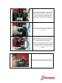
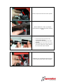
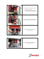
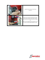
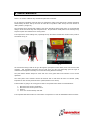
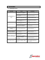
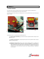
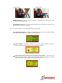
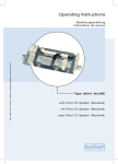
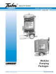
1
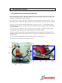
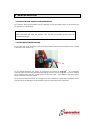
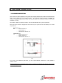
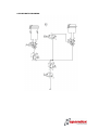
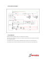
OPERATING MANUAL
AUTOMATIC PNEUMATIC MACHINE TO SET
EYELETS (GROMMETS) AND WASHERS
ImagePerfect MODEL: EP-300
WARNING:
SPANDEX DECLINES ANY LIABILITY ABOUT THE INCORRECT USE OR
MISUNDERSTUNDING ABOUT THIS OPERATING MANUAL.
INDEX
1
INTRODUCTION. ........................................................................................ 3
1.1
1.2
2
TECHNICAL DATA....................................................................................... 4
2.1
2.2
3
INSTALLATION POSITION REQUIREMENTS. ...........................................................6
PENUMATIC INSTALLATION.................................................................................6
TRANSPORT......................................................................................................7
UNLOADING AND LEVELLING. .............................................................................7
LIGHTING CONDITIONS. ....................................................................................7
LEARNING INSTRUCTIONS..................................................................................7
MACHINE OPERATION................................................................................ 9
4.1
4.2
4.3
4.4
5
MACHINE SPECIFICATIONS AND OPERATION. .......................................................4
MAIN TECHNICAL DATA......................................................................................5
INSTALLATION. ......................................................................................... 6
3.1
3.2
3.3
3.4
3.5
3.6
4
INTRODUCTION. ...............................................................................................3
MACHINE IDENTIFICATION AND “CE” MARKING.....................................................3
MACHINE DESCRIPTION. ....................................................................................9
CHECKING THE MACHINE BEFORE STARTING. ..................................................... 10
EYELET SETTING. ............................................................................................ 11
OTHER MACHINE APPLICATIONS. ...................................................................... 11
ADJUSTMENTS. ........................................................................................ 12
5.1
5.2
WARNINGS ABOUT THE ADJUSTMENTS. ............................................................. 12
DIES CHANGING FOR SAME DIMENSION. ........................................................... 12
6
MANTEINANCE. ........................................................................................ 18
7
FAILURES................................................................................................. 19
7.1
8
SAFETY. ................................................................................................... 20
8.1
9
TROUBLESHOOTING. ....................................................................................... 19
SAFETY DEVICES............................................................................................. 20
ANNEX. .................................................................................................... 22
9.1
9.2
9.3
9.4
9.5
SPARE PART LISTIG. ........................................................................................ 22
SUPPLIED TOOLING. ........................................................................................ 22
PNEUMATIC DRAWING. .................................................................................... 23
ELECTRICAL DRAWING..................................................................................... 24
GUARANTIES. ................................................................................................. 24
1 INTRODUCTION.
1.1 INTRODUCTION.
This machine has been designed to set eyelets and washers, making in just one operation the feeding
of the eyelet and washer, cutting and setting. This unit has been specially manufactured to set Image
Perfect plastic eyelets.
EP-300 has been designed to set eyelets on PVC banner materials, on fabrics might create wrinkles as
it is not possible to make adjustments in the tooling.
The standard eyelets holes are Ø8, Ø12 and Ø16 mm.
WARNINGS:
Lack of knowledge about the machine usually will lead operator to elemental doubts
about its operation.
Please read carefully this operating manual to safety operate the machine and to
optimize machine’s capability.
-
1.2 MACHINE IDENTIFICATION AND “CE” MARKING.
Each machine has a data plate on the side, made on aluminum. The following specifications are on it:
-
Manufacturer’s name and data.
Year of production.
Model and serial number.
Maximum air pressure (in bars).
“CE” mark.
Weight.
2 TECHNICAL DATA.
2.1 MACHINE SPECIFICATIONS AND OPERATION.
EP-300 is mounted on a plastic (PE) table with four wheels on the corners and one in the center, all of
them with breaking system. It has been designed to set fully automatic eyelets and washers, only
eyelets or just to punch holes on the material.
The machine has a main head where all the parts are located (fixed and moving ones), such us
pneumatic cylinder, setting dies, safety, deposits, eyelets and washers raceways, electronic controls
…
Inside the red cover are the electronic controls (PLC, power source, fuse ...), the pneumatic cylinder
and the feeding mechanism. On right hand side are the electro valves, emergency stop, on/off switch
and setting button.
EP-300 is delivered on wheels to work on ground level or over a table. If customer needs to work on
a fixed position, the breaks of the four wheels should be on for safety reasons.
Once the machine has been place on its permanent location, without fitting the air hosepipe into the
connection, verify that it has not suffered any blow or breakage while being transported and it has not
any loose parts.
EP-300 do not have adjustments in terms of setting pressure or cutting pressure.
The operation of the machine is very simple (see Fig. 1):
(C)
(A)
(B)
(D)
(X)
Fig. 1
(E)
(G)
(F)
As seen on Fig. 1, eyelets are on the deposit (A) and washers on the deposit (C). Both deposits have
220 V motor. When turning, eyelets and washers come down through the raceways (B) and (D)
towards the feeding area (G) where setting dies are located to make cutting and closing of the eyelet.
1.
EP-300 is controlled by a PLC located inside the red cover of the machine. When pressing the
setting button (F), the feeding system located on the back of the machine will be pushed to
the front by a small pneumatic cylinder, feeding one eyelet and one washer from the
raceways to the feeding area (E).
2.
The main pneumatic cylinder inside the red cover will make its vertical axle to descend.
Attached to its lower part there is the top setting die with a puncher. The aim of the
downward movement of the axle is to cut a hole with the puncher and as an effect of the
pressure that the top die does on the bottom one, to set the eyelet (grommet) on the setting
area “X”.
3.
Once the cutting is made, the shaft will continue pressing down, making the eyelet to roll and
close, holding the washer.
4.
All parts will return to its starting position leaving the machine ready for another cycle.
2.2 MAIN TECHNICAL DATA.
The main technical data of this machine are:
Width x Depth x Height
Weight
Air pressure
24 cm x 32 cm x 41 mm.
48 Kg
6 bars / 87 psi.
3 INSTALLATION.
3.1 INSTALLATION POSITION REQUIREMENTS.
The minimum space recommended must be sufficient to keep that safety space in all directions for
the operator to work properly.
WARNINGS:
Please note that that both the electrical wire and the air hosepipe should never be
completely stretched.
3.2 PNEUMATIC INSTALLATION.
The machine has an air inlet valve, type quick acting coupler (ISO 6150-B standard) ∅8 mm, located
in the back of the machine (H).
(H)
Fig. 2
For an optimal operation, the supply of compressed air should be 6 Kg/cm2. It is important,
especially when working with Ø16mm eyelets that the pressure doesn’t drop after one of two settings
as the machine might not have enough power to close the eyelet. If this happens you will require a
bigger compressor with more power.
We recommend that the flexible air hosepipe from the compressor or pneumatic installation comes
from the top of the building to avoid operator’s injuries or damages on the equipment.
3.3 TRANSPORT.
Always unload the crate with a forklift, securing the load with slings on the sides.
To transport the machine to its permanent location, the following precautions should be taken in
account:
-
Never stand beneath the wood crate.
Use protective gloves.
Avoid balancing the machine.
Never overturned the machine.
Lift or move the load gently.
Do not make sudden movements.
Always move the machine in vertical position.
The machine is delivered with appropriate packaging to avoid shocks and frictions during transport.
In the event that for some reason it is necessary to transport again the machine after its installation
and the customer does not have the original packaging, we advice to use a reinforced package made
of wood.
3.4 UNLOADING AND LEVELLING.
EP-300 is delivered fixed to the wood crate with screws on both sides of the plastic (PE) platform.
Please follow these steps:
-
Open the wooden crate.
Remove the protective film.
Loosen the screws on both sides of the plastic (PE) platform that tight the machine to the
base of the crate.
Move the machine to its location with a hand pallet truck.
If the machine will work on a bench, it must be strong enough and leveled. Before any operation with
the equipment, the four breaks on the wheels must be on.
3.5 LIGHTING CONDITIONS.
A safe operation and servicing of the machine requires a minimum lighting of 300 lux.
3.6 LEARNING INSTRUCTIONS.
Please read carefully these instructions before starting:
-
Before connecting the machine to the power supply, compressor or to customer’s pneumatic
installation, it should be place on its permanent location.
-
The cleaning, handling or replacement of parts should always be made with the air inlet valve
shut and the power off.
-
Do not remove from the machine the safety devices, stickers or warning sings that point out
dangerous areas. In case of withdrawal by force majeure, please remember to place them
back before using the machine again.
-
The machine has an air inlet valve “H” (fig. 2) to manually open and close the air supply to
the machine; When the machine is not in use, it should be shut (see fig. 3) to avoid accidents
when use by a third party.
We also suggest disconnecting the hosepipe from the
compressor/air supply for safety reasons.
-
The machine has an ON/OFF switch (G), (see Fig. 1). When the machine is not in use, it
should be on OFF position, (no lighting on the switch) to avoid accidents when use by a third
party. We also suggest unplugging the electrical cord from the socket for safety reasons.
The dangerous area of the machine is the cutting and setting area that is protected by an acrylic
shield and the stainless steel plate. Never access this area with the main switch on ON position and
the air inlet valve open.
(Setting area “X”)
Fig. 3
Operator should pay attention to the position of the air inlet valve (H) (See Fig 2) located on
the back of the machine. When the valve changes its position from open to close, the
compressed air on the internal circuit of the machine is expelled, preventing any unexpected
action from the pneumatic cylinder if by accident the pedal is pressed.
CLOSE position
Fig. 4
OPEN position
Fig. 5
4 MACHINE OPERATION.
4.1 MACHINE DESCRIPTION.
This machine has been designed to set eyelets with washers, feeding the machine automatically both
parts, on PVC coated material and in general terms on plasticized materials, but not on fabrics as it
might create wrinkles due to its setting system. The maximum cutting diameter is 16 mm (the
machine is supplied, adjusted and ready to use with the eyelet size required by customer on its order,
standard is 12 mm).
The machine feeds the eyelet, the washer, cuts the material and sets in just one operation.
Each set of dies has been designed to work with only one eyelet size with its washers, the models
may differ on:
⇒
EYELET
o
o
o
⇒
WASHER (J):
o Outside diameter “F”.
o Washer height “H”.
o Internal hole diameter “i”.
(I):
Head diameter “D”.
Eyelet height “L”.
Internal hole diameter “d”.
(I)
(J)
Fig. 6
If you need to set different eyelet sizes, you will require different machines as it not possible to
change models.
Spandex disclaims any responsibility when using the machine for different uses than the ones covered
on this operating manual.
4.2 CHECKING THE MACHINE BEFORE STARTING.
Before using the machine for the first time, or when the location of the machine is changed, or
adjustments or part replacements are made, we advice customers to check that the machine has not
suffered a blow or breakage.
The main controls are on the right hand side of the machine:
(K)
(H)
(G)
(F)
Fig. 7
4.3 EYELET SETTING.
1.
Check that the air inlet valve “H” is on OPEN position (fig. 5).
2.
Check that the main switch (G) is on ON position (with the green light on).
3.
As soon as the machine is on position “ON”, the engines on both deposits will start to
turnaround. The brushes push out the eyelets and washers filling the raceways. To extend
the life of the engines, they will stop when operator is not using the machine for a period of
25 seconds. First time on is pressed will run for 90 seconds to fill raceways.
4. Place the banner over the stainless steel plate underneath the safety protection (L) (see Fig.
8).
5. Press the setting button (F) so the eyelet and the washer are moved to the front and the main
shaft comes down making the cutting of the material and the setting of the eyelet.
6. There is safety timing in between one setting and the next so all moving parts have enough
time to return to its original position.
After it, the machine will be ready to set another
eyelet.
(L)
(Banner)
Fig. 8
4.4 OTHER MACHINE APPLICATIONS.
To cut holes on the material, without setting eyelets, it will not be necessary to install specific tooling;
it will be possible to make it with the same ones use to set the eyelets. Hole diameter will not be
more than 16mm.
5 ADJUSTMENTS.
5.1 WARNINGS ABOUT THE ADJUSTMENTS.
The parts that should be replaced on a regular basis due to normal wear are the cutting or bottom die
“M” and setting or top die “N”. We will see that the parts need to be replaced when either the cutting
or the setting is not accurate. We always recommend having a spare set of these parts on your
stock.
(M)
(N)
Fig. 9
When doing maintenance operations if by any reason it is necessary to remove parts meant for
operator safety (safety protection, stainless steel plate ...) remember to put them back where they
belong and fasten them firmly.
WARNING: Shut the general air inlet valve to CLOSE position (see Fig. 4) and main switch “G” on
OFF (no lighting) to change dies, install optional equipment or any other handling.
5.2 DIES CHANGING FOR SAME DIMENSION.
Whenever is necessary to replace the dies for its normal wear you should follow these steps:
WARNING:
To install a new set of dies it will be necessary at some point to take out the safety protection
“L” (see Fig. 8). ALWAYS place it back before using the machine again.
Please be very careful while doing adjustments, always making sure that your hands and
fingers are out of the setting area (X) (see Fig.3) and that nobody can press the setting
button (F) (see Fig. 7) that will start the setting operation catching hand or fingers.
On the back of the machine are the electro
valves (3) that distribute the compressed air to
run the different operations needed to set the
eyelets. The first one controls the main
cylinder (that has the top die) and has an
orange switch. On its back has a label “EV2”
With one finger press the orange switch and do
not remove it. The axle of the cylinder will
descend.
Without releasing the finger on the switch,
shut off the air inlet valve so the axle of the
cylinder stays on its lower position.
When the valve changes its position from open
to close, the compressed air on the internal
circuit of the machine is expelled, preventing
any unexpected action from the pneumatic
cylinder.
With an allen wrench, loosen the four screws of
the safety cover on the front of the machine.
Remove the set screw from the top die.
IT IS IMPORTANT NOT TO DAMAGE THE
MACHINE THAT YOU REMOVE THE SCREW
FROM THE DIE, NOT JUST LOOSEN IT.
Remove the set screw from the bottom die.
IT IS IMPORTANT NOT TO DAMAGE THE
MACHINE THAT YOU REMOVE THE SCREW
FROM THE DIE, NOT JUST LOOSEN IT.
Open the air inlet valve so axle of the cylinder
moves towards its upper position.
Close the air inlet valve to access the setting
area.
Remove top die form the axle of the cylinder.
Remove bottom die. Place your fingers
underneath the stainless steel plate and lift it
gently.
1.
2.
3.
Remove from the new die the set
screws (top & bottom).
Assemble new die putting both parts
together.
Check that the holes of the set screws
are on the same side, as they have to
be on the front of the machine.
Install the new die with the holes for the set
screws looking to the front of the machine.
With your hands out of the setting area:
1.
2.
Open the air inlet valve.
Press the switch of the first electro
valve so axle of the cylinder descends.
Without removing your finger from the first
electro valve, close the air inlet valve.
With an allen wrench, install back the set
screw of the top die.
With an allen wrench, install back the set
screw of the bottom die.
Tighten the four screws of the safety
protection.
Open the air inlet valve and with your finger
press the first switch of the electro valve to
check that the top die fits well into the bottom
one.
Once we have finished these operations we will
be ready to start making settings as usual.
6 MAINTENANCE.
There is no need to lubricate any mechanical parts of the machine.
For an optimum operation of the EP-300 it is important to have some parts clean, and this operation
should always be done with a) the main air inlet valve on position “OFF” and b) the main switch on
“OFF” position (no light on).
The raceways where eyelets and washers come down should be always kept clean; we recommended
doing it at the end of the day with compressed air. Any threads or small parts on the raceways may
stop the eyelets and washers from coming down.
It is important to clean setting area, especially the top die where threads will remain on the puncher
as marked on Fig. 9.
Fig. 9
Fig. 10
We recommend doing it with an air gun through the open space on the safety cover in the front of the
machine. This operation should be done at least once per day, but depending upon the type of
materials used might be necessary to increase the timing between cleaning.
The push button should always be clean and clear of any parts that could interfere on its normal
operation.
The outer parts of the machine should be cleaned with a cloth that will leave no threads (really
important on the raceway channels were eyelets/washers come down).
If the machine is going to be a long period with no use please follow these recommendations:
1.
2.
3.
4.
Disconnect it from the compressor
Disconnect it from the power source.
Clean it.
Cover it to avoid humidity and dust.
It is important that the machine is connected to a compressor or local air installation with an air filter.
7 FAILURES.
7.1 TROUBLESHOOTING.
PROBLEM
CAUSE
SOLUTION
1. Check that the air hosepipe is
connected to the compressor.
1. Connect the air hosepipe.
2. Check that the air inlet valve is
on open position.
2. Open the air inlet valve.
3. Check that main switch of the
machine is on position “ON” (with
light).
4. Change the position to “ON”.
3. Check that the air pressure on
the circuit is 6Kg/cm2.
3. Adjust the pressure gauge until
the manometer has the correct
pressure.
1. Check that the air pressure on
the circuit is 6Kg/cm2.
1. Adjust the pressure gauge until
the manometer has the correct
pressure.
2. The edge of the bottom die is
either worn out or damaged.
2. Change the die.
The eyelet crushes when
setting.
1. Check that the pressure of the
circuit is no more than 6 Kg/cm2.
1. Adjust the pressure with the
manometer to 6 Kg/cm2.
Suddenly the eyelet does
not close completely.
1. Check that the pressure of the
circuit is 6 Kg/cm2.
1. Adjust the pressure with the
manometer to 6 Kg/cm2.
1. Check that there are is nothing
blocking the exit of
eyelets/washers in the deposits.
1. Stop the deposits and clean the
hole where eyelets/washers come
out.
2. Check that the deposits
(especially on the washer’s one) is
not overload.
2. Take out part of the load so the
brushes can turn freely.
1. Check that the position of the air
inlet valve is completely in OPEN
position.
1. Move completely the valve to
OPEN. When is set halfway the air
will be expelled.
The machine does not
work.
The machine does not cut.
Washers /Eyelets do not
come out of the deposit
The machine leaks air.
8 SAFETY.
8.1 SAFETY DEVICES.
The machine has a range of protection devices to prevent operator (except on maintenance or
repairs) from accessing dangerous areas where can be injured.
The dangerous part of the machine is the setting area “X”, where operator has the risk of crushing his
fingers or hands.
(K)
(H)
(G)
Fig. 12
(F)
(X)
(L)
Fig. 11
(O)
The dangerous area “X” is protected by the following devices:
⇒
Acrylic safety protection (L): Prevents the access of operator’s hands or fingers to the
setting area.
⇒
Stainless steel plate (O): This plate prevents the access of operator’s hands or fingers
to the dangerous area.
⇒
General air inlet valve “H”: This valve allows manually opening or shutting the
pneumatic air supply from the compressor or general air installation. As safety device, it
has a decompressing system, when the valve changes its position from open to close; the
compressed air on the internal circuit of the machine is expelled, preventing any
unexpected action from the pneumatic cylinder when making assembling or adjustments
on the machine.
CLOSE position
OPEN position
Fig. 13
Fig. 14
⇒
Main switch “G”: When set on “OFF” position (no light) will not set eyelets even if you
press the setting button (F).
⇒
Emergency stop “K”: It will cut all power off when use by operator in case there is an
emergency running the equipment.
There are a series of labels on the machine that operator should read:
⇒
Label “Read manual”: This label on left hand side of the cover of the machine explains
operator that is mandatory to read the operating manual.
Fig. 15
⇒
Label “Danger”: This label on the front of the cover informs operator that there is
danger of crashing hands and fingers when manipulating this area.
Fig. 16
⇒
Label “Disconnect the machine before taking out protection”: This label on the
right of the cover informs operator that before taking out any protection the machine
must be disconnect it (shut air inlet valve) and main switch off.
Fig. 17
9 ANNEX.
9.1 SPARE PART LISTIG.
REFERENCE
DESCRIPTION
EP-300 Die 12mm
EP-300 Safety protection
EP-300 Brushes
EP-300 Acrylic deposit cover
9.2 SUPPLIED TOOLING.
REFERENCE
ALLEN # 3
DESCRIPTION
QUANTITY
1
9.3 PNEUMATIC DRAWING.
9.4 ELECTRICAL DRAWING.
9.5 GUARANTIES.
Model EP-300 has a guarantee period of 12 months since purchasing.
Within this period, Spandex will replace free of charge all spare parts that under Spandex knowledge
have manufacture defects
The guarantee will not cover assemble / disassemble of the unit but will cover their freight cost.
The guarantee will not cover those parts with normal wear for the machine use as the setting dies.