1
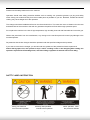
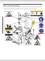
TIRE CHANGER
INSTRUCTION MANUAL
VERSION:B
0
Dear customers,
Very pleased that you will purchase and use the tire changer produced by our company
We are the comp any w ith reput ation of qua lity. W e sincerel y w ish to produce quality
goods under the ISO9001Quaality sy stem and ge t the EU CE certificate to help y
ou
promote your business.
Carefully read this o perational manual before installation and use this operation manual.
And also keep it with care for future reference.
WARNING
This instruction manual is the important part of the product. Please read it carefully and keep It properly.
This machine is only applied to mount, demount and inflate the tire in the specified scope and not for any other
purpose.
The manufacturer will not be responsible for the damage or injury caused for the operation not properly and out of
the range.
NOTE
This machine should be operated by the special trained qualified personnel. When operating, the unauthorized
personnel will be kept far away from the machine.
1
Please note the safety label stuck on the machine.
Operators should wear safety protective facilities such as working suit, protective glasses, eye plug and safety
shoes. Keep your hands and body from the movable parts as possible as you can. Necklace, bracelet and loosen
clothing may cause dangerous to the operators.
Tire changer should be installed and fixed on the flat and solid floor. The more than 0.5m of distance from the rear
and lateral side of the machine to the wall can guarantee the perfect air flow and enough operation space.
Do not place the machine in the site of high temperature, high humidity, dust and with flammable and corrosion gas.
Without the permission from the manufacturer, any change on the machine parts will cause injury/damage to the
machine/operator.
Pay attention that the tire changer should be operated under the specified voltage and air pressure.
If you want to move the tire changer, you should under the guidance of the professional service personnel.
Notice: During opera tion, one operator is requi red for working on the w heel weighing belo w 25kg, two
operators required for the 25-50kg wheel, and wheel lifting equipment for wheels heavier than 50kg.
SAFTTY LABEL INSTRUCTION
Keep your hands far
from tire when operation
Carefully read operation
manual before operation
2
When operation , wear
the protective facilities
electrical shock!
When
rapid
ensure
inflation,
the
wheel
clamped.
Do not reach any part of your
body under the demount tool.
When operation, do not
wear long hair, loosen
clothing and jewelries..
When breaking bead, the bead Breaking
blade will quickly move leftwards.
When operation, do not
reach y our hand under
the falling objects.
Note: when press the tire, the
opened clamp cylinder may
injury the hand of the operator.
Remember, do not touch the side
Wear the goggle
wall of the tire.
When clamping the rim, do not
Reach your hand or other parts
Of the body in between the clamp
Read the user manual
& the rim.
Do not stand behind the column to
Avoid the column from injuring the
persons when swing.
Wear the gloves
3
SAFETY LABEL POSITION DIAGRAM
Pay attention to keep the safety labels complete. When it is not clear of missing, you should change the new label.
You should let the operators see the safety labels clearly and understand the meaning of the label.
4
CONTENT
CHAPTER Ⅰ BRIEF INTRODUCTION
1.1BRIEF INTRODUCTION………………………………………………………………………………………………….6
1.2EQUIPMENT OVERALL DIMENSION (EXCLUDING THE ASSSISTANT) ……………………………………….6
1.3 TECHNICAL PARAMETER………………………………………………………………………………………………6
1.4 APPLICATION SCOPE……………………………………………………………………………….…………………..6
1.5ENVIRONMENT REQUIREMENT …………………………………………………………………………..…………..6
CHAPTER Ⅱ CONFIGERATION AND OPERATION…………………………………………………………………….6
CHAPTER Ⅲ INSTALLATION AND CALIBRATION…………………………………………………………………….7
3.1 OPEN PACKAGE CARTON……………………………………………………………………………………………..7
3.2 INSTALLATION …………………………………………………………………………………………………………..7
3.3AIR SOURCE INSTALLATION………………………………………………………………………………………….9
CHAPTER Ⅳ DEMOUNT AND MOUNT TIRE…………………………………………………………………….….….10
4.1 DEMOUNT TIRE……………………………………………………………………………………………….…….….10
4.2 MOUNT TIRE………………………………………………………………………..…………………………….…….11
4.3 INFLATION…………………………………………………………………………………………………………..…..11
CHAPTER Ⅴ MAINTANENCE AND REPAIR………………………………………………………………………...…12
CHAPTERVI TRANSPORTATION…………………………………………………………………………………..…13
CHAPTER Ⅶ ELECTCTRICAL AND PENUMATIC DRAWING……………………………………………………….14
CHAPTER Ⅷ GENERAL TROUBLESHOOTING AND SOLUTION ………………………………………………….15
CHAPTER IXPACKAGE LIST &OPTIONAL ACCESSORIES…………………………………………………………17
APPENDIX……………………………………………………………………………………………………………………18
5
CHAPTER Ⅰ BRIEF INTRODUCTION
1.1BRIEF INTRODUCTION
This series of equipment is the tire changer with fixed
column and rocker arm tire changer. It is suitable to
mount,demount and inflate all types of motorcycle tire
with tube & tubeless. The operation is easy, convenient,
safety and reliable. It is the necessary equipment for
the auto service shop and tire shop. The model is 806.
1.2EQUIPMENT OVERALL DIMENSION
Model
806
Height
Length
Width
Net Weight
(mm)
(mm)
(mm)
kg
1750
860
750
175
FIG1
1.3 TECHNICAL PARAMETER
Operational Pressure:8-10bar
CHAPTER Ⅱ CONFIGERATION AND
Motor:50Hz ±1% 400V±1% 0.75kW
Turntable Rotation Speed:6rpm
OPERATION
Noise:<75dB
Note: An over-voltage protection device is needed
for the connection with power supply
1.4 APPLICATION SCOPE
model
max. wheel
max. wheel
rim diameter
diameter
width
(external
clamping)
806
960mm(37″)
254mm(10″)
6″~24″
1.5ENVIRONMENT REQUIREMENT
ambient temperature 5℃~45℃
relative humidity 50%@40°C -90%@20°C
sea level max.1000m
without dust and flammable and explosive gas
The operation space around the machine wills not
smaller then the indicated in FIG1
If the machine is installed outdoors, it must have the
protective shed to avoid being exploded to the rain and
sunlight.
FIG2
It is forbidden to use in the site with the
flammable gas!
6
1-vertical shaft spring
2 - rocker arm
3- hexangular shaft
4- demount tool
5- claw
6- turntable
3.2 INSTALLATION
7- turntable cylinder
8- operation panel
9- clamp pedal
10- press tire pedal
4-3)and column assembly(FIG 4-2). And position and
11- turntable pedal
12- crowbar
fix according to the FIG5. Remove the bolt, elastic
13- blade
14-bead breaking cylinder
washer on the body (FIG 4-4).
15- bead breaking arm
16- air source
17- lock handle
18 - column
3.2.1After un-package the package carton, take out
accessory boxes(FIG 4-1),bead breaking arm(FIG
washer and plate
CHAPTER Ⅲ INSTALLATION AND
CALIBRATION
Before installation and debug, carefully read this
manual. The unauthorized change on the parts and
spare parts of the machine will cause the damage on
the machine.
Installation and debug personnel should have the
FIG4
specific electrical knowledge.
Operators must be trained and authorized.
Before installation, carefully read the equipment list. If
any question, please contact with the dealers or our
company. To ensure the success of the installation and
debug, please prepare the following common tools:
Two wrenches ( 10″ ) , one socket wrenches, one
hexangular wrench, one tung, one screw driver, one
hammer and one millimeter
The tire changer must be fixed on cement ground by anchor
bolts fastened through its 4 base frame holes.
The tire-changer must be fixed to the ground by means of
suitable anchoring bolts.
FIG5
3.2.2 Place the column on the body. The direction of the
warning label is forwards. Make the holes on the
3.1DEPACKAGE
column base plate align to thread holes on the body.
3.1.1 According to the de-package instruction on the
Once again assemble the removed the bolt, elastic
package box, to detach the box and remove the
washer and plate washer and plate washer removed in
package material to check if the machine damage or
3.2.1The torque is 70 N·M(FIG5)Use torsion wrench to
not and if the spare parts completed.
tight
3.2.3 Use the wrench to remove the screw(FIG 6-3)
3.1.2Keep the package material far away from the
hexangular shaft(FIG6-1)and take off the vertical shaft
working site and deal with it properly.
cap( FIG 6-2)
. When remove the screw on the vertical
7
shaft cap, you need use the lock handle to lock the
hexangular shaft to avoid sliding off to damage the
machine or injury personnel!
Install the vertical shaft spring(FIG7-1)on the vertical
shaft. Mount the vertical shaft cap and mount the
removed screw and assemble the hand wheel into the
nut bushing of the rocker arm(FIG 7-2)
。
3.2.4Remove the lock nut at the front end of the bead
breaking cylinder piston rod(FIG 8-1)and use the
wrench to remove the nut on the bead breaking arm
bolt(FIG8-4) Remove the bolt(FIG8-3)and hang the
spring(FIG8-2)
FIG 8
3.2.5Position the bead breaking arm shaft bushing into
the bead breaking support plate on the body(FIG 9-1 to
align the hole and install the bead bre3aking bolt
(FIG9-2)and assemble the nut to lock(FIG 8-4).
Insert the piston rod(FIG10-2)through the hole of the
bead breaking slide bushing(FIG10-1). The surface
of the slide bushing should be outwards(FIG 10).
Assemble the removed nut(FIG 8-1)into the front end
of the piston rod. The nut will be assembled. The
distance from the edge of the bead breaking blade to
the bead breaking rubber is 30~40mm(FIG11). Hang
the spring.(FIG9-3)。
FIG6
FIG 9
FIG 7
8
ø8 PU hose on the lateral side of the body. This
connect is equipped for avoid the air hose from sliding
into the body. And plug into the elbow. See FIG14.
FIG 10
FIG 13
3.3 AIR SOURCE INSTALLATION:
3.3.3 Connect the inflation gun: Plug the inflation gun
Air source has been adjusted before ex-factory. If it
connect into the slot of the open nut(FIG15)and tight
needs change, adjust again
the open nut and then connect air supply.
3.3.4 Air source has been adjusted before ex-factory. If
3.3.1 Take out the air source and 2 screws from the
it needs change, adjust again:
accessory boxes and remove the oil and dust. Fix the
Pressure:
screw on the right side of the body(FIG12)
button( FIG16-1 ) and twist clockwise and the air
Lift
up
the
pressure
adjustable
pressure will increase. Meanwhile, if counterclockwise,
the air pressure will decrease.
Oil Feed:Use screw driver to twist the screw(FIG16-2).
If clockwise, the oil dropping speed will slow. If
counterclockwise,
it will become fast.
FIG 11
FIG 12
FIG 15
FIG12
3.3.2 Connect air hose: Remove the connect of on the
9
and tire pressing runner clog (FIG 18).Then step down
the pedal to detach the rim from the tire. Repeat the
same operation on the other parts of the tire to make
the tire completely detached from the rim.
Place the wheel with the lip detached from the rim on
the turntable. Step the clamping pedal (FIG 2-10)to
clamp therim. You can select the internal and external
clamping according to the rim. When pressing the tire,
you should use the brush to spread the thick soap liquid
to lubricate the lip.
4.1.3Position the hexangular shaft (FIG 2-3) to the
working position to make the demount tool close to the
FIG16
rim of the wheel. And use the hand wheel (FIG 7-2) to
push against the rocker arm and then use the lock
handle( FIG 2-17) TO LOCK. The demount tool will
CHAPTER Ⅳ DEMOUNT AND MOUNT TIRE
automatically move a little of gap (FIG19).
The angle of the demount tool has been calibrated
4.1 DEMOUNT TIRE
according to the standard rim 13"). If handling the
4.1.1 Deflate the air in the tire completely. Use the
extra-big or extra-small rim, you can reposition.
special tool to detach the weight on the rim and pull out
the core (FIG17).
FIG 17
FIG 19
FIG 20
FIG 18
4.1.4 Use the crowbar to detach until the lip to the
4.1.2 Place the tire between then bead breaking blade
hump of the demount tool (FIG20). Step the turntable
10
rotation pedal ( FIG2-11 ) to rotate the turntable
reach your hands in between the rim and the claw to
clockwise until the entire lip completely detached. If
avoid the damage to the personnel.
handling the tube tire, to avoid the damage on the tube,
you should keep the nozzle of the tire 10cm from the
right side of the demount tool when demounting. If the
demount of the tire is jammed, please stop the machine
immediately and then lift up the pedal to let the
turntable rotate counterclockwise to remove the
resistance!
4.1.5 When handling the tube tire, Take out the tube
and then move the lower lip upwards to the upper edge
of the rim and then repeat the above steps to detach
the other lip .In the process of demounting tire, you
should keep your hands and the other parts of your
body from the movable parts. Necklace, bracelet and
the loose clothing can injury personnel!
4.2 MOUNT TIRE:
FIG 22
Before mount tire, check if the tire and rim are of the
same dimension!
4.2.1 Clean the dirt and rust on the rim and lock it on
the chuck.
4.2.2 Spread the lubrication liquid or soap liquid around
the lip. Tilt the tire against the rim and keep the front
end upwards. Press down the hexangular shaft to
move the demount arm to contact with the rim and lock.
The left lip above the tail of the demount tool and the
right lip will be positioned under the front end of the
demount tool (FIG 21),Clockwise rotate the turntable to
guide the bottom lip into the tire detaching slot.
FIG 23
4.3 INFLATION:
When inflating the tire, please be carefully and series
obey the operation process. Check the air route to see
if the air connection is OK. This machine is equipped
with an inflation gauge for monitoring the inflation of the
FIG 21
tire and the inflation pressure(FIG2-23).
1. Loose the tire from the turntable.
4.2.3If there is tube, place it in the tire and plug the core.
And assemble the lip according to the above mentioned
2. Connect the inflation hose with the tire air core. See
step(FIG22). In the process of clamping the rim, do not
FIG23.
11
and use the machine oil to lubricate.
3. In the process of inflation, you should repeat
Use the diesel oil to clean the turntable claw and guide
switching the inflation gun to confirm
rail and use the lithium base grease to lubricate.
(FIG25)
the pressure indicated on the pressure gauge not
Periodically check the lubrication oil level in the oil fog
exceed the scope specified by the manufacturer.
device. If the oil level lower than the oil scale, please
feed in the SAE30 lubrication oil in time(FIG 26)
4. If the inflation pressures too high, you can press
Drain out the water and impurity in the oil water
down the deflation press button on the inflation device
separator one time every day.
to reach the required air pressure.
Periodically check and adjust the tension of the driven
belt. Properly adjust the adjust nut in A and B to realize
the
Warning!Explosive!
proper tension.(FIG27)。
When inflating, please obey the following instructions:
Check all the connect parts and tight the loosen bolt.
*Carefully check if the tire and the rim are of the same
dimension and check the wear condition of the tire to
confirm the tire not damaged before inflation.
* When the air pressure needed for inflation relatively
high, you can take off the tire and to inflate under the
protective cover.
* When inflating the tire, please be carefully. Keep your
hands and body away from the tire.
FIG 24
Chapter V MAINTANENCE & REPAIR
NOTE:
Only the qualified professional personnel can execute
the maintenance. Before any maintenance, Cut off the
power .And ensure the maintenance personnel can
take charge of the power plug. Meanwhile, cut off the
air supply and pull off the quick adaptor of supply and
completely deflate the residual air in the machine.
To correctly use the tire changer and prolong its
working life, it is necessary to periodically maintenance
and repair according to the instruction manual. Or the
FIG 25
running and reliability of the machine will be affected
and the personnel near the machine or the operator will
be injured.
Keep the machine and working area clean.
HEXANGULAR SHAFT & LOCK PLA
LOCK GAP ADJUSTMENT
Use the diesel oil to clean the hexangular shaft (FIG24)
When press downward the hexangular lock handle, the
The following position should be monthly maintenance:
12
TE
hexangular shaft will vertically slide under the effect of
FIG28
the weight of the hexangular shaft and return spring.
When the lock handle rotate clockwise for about 100
CHAPTER VI TRANSPORTATION
degree, the cam connected to the handle will push up
The machine must apply the original package to the
the lock plate to lock the hexangular shaft. If you can
transportation and position
not realize this situation, you can reach the target to
according to the indication on the package. The
lock the hexangular shaft through adjusting the position
transportation of the machine
of the screws and nuts.(FIG 28)
must use the corresponding forklift(FIG 29)and the
stack should not exceed
3 layers.
1
figure
instruction
light
up
moist-proofing one layer gravity center hoist from here
FIG 29
STORE AND TRANSPORTATION
On the vertical surface, there are
corresponding identification to show the
basic requirement on the store and
transportation.
STORE IDENTIFICATION
FIG 26
STORE ENVIRONMENT
a.temperature:-5~+55°C;
b.humidity:≤ 90%;
c.Without cor rossive gas and keep away from
falmable and explosive objects and have
methods to protect rain and snow.:
FIG 27
d.In the process of transportation,meet the
basic requirement of the identification.
13
CHAPTER Ⅶ ELECTCTRICAL AND PENUMATIC DRAWING
8.1. 220V ELECTRICAL PRINCIPLE DRAWING
8.2PNEUMATIC PRINCIPLE DRAWING
8.1. 220V ELECTRICAL PRINCIPLE DRAWING
2
Cables provided by the user
2
Motor reverse
switch
ELECTRICAL ELEMENT LIST
Item No
Description
1 Motor
2 Po
3 Chan
4
5 plug
wer Cable
ge-over Switch
Circuit breaker
Model
Quantity
YC90S2-4/0.75KW/50HZ/400V
1
4*1.5mm2
1
TCS4S340-33345
1
5SJ16D 20A/400V
1
TYPE 014
1
14
Remark
8.2. PNEUMATIC PRINCIPLE DRAWING
φ70/20X262
φ70/20X262
φ186/20X150
半自动气动原理图
CHAPTER Ⅷ TROUBLESHOOTING ANALYZE AND SOLUTION
Item NO
1T
2
3
DESCRIPTION
MODEL
QUANTITY
ri-link
AF-2000
1
Three Digital Valve
Two Digital Valve
4 Inflation
Gun
1
Manufactured in the factory
1
Manufactured in the factory
1
15
REMARK
TROUBLESHOOTING
REASON
SOLUTION
Turntable rotates in one direction.
Universal switch contact burned
Change Universal switch
Turntable does not rotate.
Belt damage
Change belt
Belt too loose
Adjust the tension of the belt
Motor or power source have problems
Check motor, power source and power source
cable
Universal switch contact damage
Change motor
Change Universal switch
Turntable can not clamp the rim as
Claw worn
Change claws
normal
Clamp cylinder air leakage
Change the air leakage sealing parts
hexangular shaft
Lock plate not in position
See Chapter V
Chassis pedal not return.
Pedal return spring damage
Chang torsion spring
Motor not rotate or the output
Drive system jam
Remove the jam
torque not enough
Capacitor broken down
Change capacitor
Voltage not enough
Wait for the restore of the voltage
Short-circuit
Remove
Air leakage
Change sealing parts
Mechanic fault
Remove the fault
Air pressure not enough
Adjust the air pressure to meet the requirement
Air pipe damage
Change damaged parts
Pipe connect damage
Add sealing glue
cannot lock
Cylinder output force not enough
Air leakage
Sealing end damage
Sealing glue missing
16
CHAPTER IX PACKAGE LIST AND OPTIONAL ACCESSORY
Description
Item No
Quantity
complete package
non-complete package
1
Body
1
2
Column Assembly
1
3
Bead Breaking Arm Assembly
1
Accessory Box
1
1)
crowbar
1
2)
Vertical Shaft Spring
1
3)
Grease Container
1
4)
Grease Container Bracket
1
5)
Claw Protective Cover
4
6)
Demount Tool Protective Cover
2
8)
Hand Wheel
1
9)
Inflation Gun Assembly
1
11)
Air Source Connect
1
14)
Oil Water Separator
1set
16)
Operation Manual
17)
Quality Guarantee
18)
Product Certificate
Optional Accessory
19)
brush
1
20)
Blade protective cover
1
21)
crowbar protective cover
1
22)
Plastic Demount Tool(5#)
1
Note:
1. To the packaged objects, please tick “√” in the corresponding “”.
2. The accessory need to be marked the specification, please fill in the corresponding remark.
17
Remark
APPENDIXWEARABLE PARTS LIST
Item No
Description
Specification
1
Claw Cover
4
2
Demount Tool Cover
1
3
Blade Protective Cover
1
4
Y-ring
30X20X7
Quantity
2
Remark
for turntable cylinder
806 OIL SAFETY DATA SHEET
MOBIL XHP 222
ITEM
Penetration rate25℃
QUALITY STANDARD
mm/10
280
dropping point ℃
280
anticorrosion
passed
Basic oil viscosity
220
oxidize stability 100h pressure-drop
kpa
35
water lose percentage79%
5
copper corrosion
1A
SAE30# LUBRICATION OIL
ITEM
QUALITY STANDARD
density 15℃
0.893
Flash point
224
Pour point ℃
-18
viscosity 40℃
100
viscosity 100℃
11.2
Viscosity index
97
2# LITHIUM BASE GREASE
ITEM
QUALITY STANDARD
Penetration rate
mm/10
278
dropping point
℃
187
copper corrosion 100℃
24h
oxidize stability(99℃
100h)
anticorrosion(52℃
No change
0.2
1 level
48h)
similarity viscosity(-15℃、 10S¯¹)/(Pa·S)
800
water lose(35℃ 1h) %
8
CKC460 INDUSTRIAL GEAR OIL
ITEM
QUALITY STANDARD
Viscosity 40℃
461
Viscosity index
92
Flash point
Freezing point
212
℃
-26
℃
copper corrosion100℃
1A
3h
mechanical impurity
0.007
Pour point
-10
18