1
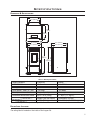
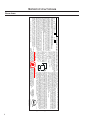
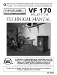
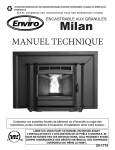
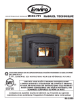
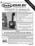
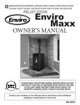
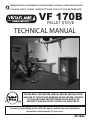
SHERWOOD INDUSTRIES IS AN ENVIRONMENTALLY RESPONSIBLE COMPANY. THIS MANUAL IS PRINTED ON RECYCLED PAPER. PLEASE KEEP THESE INSTRUCTIONS FOR FUTURE REFERENCE. VF 170B PELLET STOVE TECHNICAL MANUAL PLEASE READ THIS ENTIRE MANUAL BEFORE INSTALLATION AND USE OF THIS PELLET-BURNING ROOM HEATER. FAILURE TO FOLLOW THESE INSTRUCTIONS COULD RESULT IN PROPERTY DAMAGE, BODILY INJURY OR EVEN DEATH. Contact your building or fire officials about restrictions and installation inspection requirements in your area. 50-1864 Table of Contents Safety Warnings & Recommendations...............................................................................................3 Specifications.................................................................................................................................5 Dimensions & Specifications......................................................................................................5 Rating Label Location...............................................................................................................5 Rating Label.............................................................................................................................6 Installation.....................................................................................................................................7 Deciding Where to Locate your Pellet Appliance..........................................................................7 Removing Pellet Stove From Pallet.............................................................................................7 Clearances to Combustibles.......................................................................................................8 Hearth Shield Installation..........................................................................................................8 Thermostat Installation.............................................................................................................8 Vent Termination Requirements.................................................................................................9 Outside Fresh-Air Connection...................................................................................................10 Exhaust And Fresh Air Intake Locations....................................................................................10 Mobile Home Installation:........................................................................................................11 Corner Through Wall Installation..............................................................................................11 Horizontal Exhaust Through Wall Installation.............................................................................12 RECOMMENDED - Through Wall With Vertical Rise and Horizontal Termination Installation...........14 Through Concrete Wall With Vertical Rise Installations..............................................................14 Outside Vertical Installations....................................................................................................15 Inside Vertical Installations......................................................................................................16 Hearth Mount Installation........................................................................................................17 Slider/Damper Set-Up.............................................................................................................18 Troubleshooting............................................................................................................................19 Wiring Diagram............................................................................................................................22 Parts List......................................................................................................................................23 Parts Diagram - Components.........................................................................................................25 Parts Diagram - Steel....................................................................................................................26 Warranty......................................................................................................................................27 Installation Data Sheet..................................................................................................................28 2 Safety Warnings & Recommendations * This manual is designed for the technician in conjunction with the owner’s manual. * Please read this entire Technical Manual before installing or operating your Vista Flame Pellet Stove. Failure to follow these instructions may result in property damage, bodily injury or even death. Any unauthorized modification of the appliance or use of replacement parts not recommended by the manufacturer is prohibited. All national and local regulations and shall be complied with when operating this appliance. Caution: Do not connect to any air distribution duct or system. Warning: Never place wood, paper, furniture, drapes or other combustible materials within 80cm (31½”) of the front of the unit, 30cm (12”) from each side, and 10cm (4”) from the back of the unit. Do not let children or pets touch it when it is hot. To prevent the possibility of a fire, ensure that the appliance is properly installed by adhering to the installation instructions. An Vista Flame dealer will be happy to assist you in obtaining information with regards to your local building codes and installation restrictions. FIRE EXTINGUISHER AND SMOKE DETECTION: All homes with a pellet burning stove should have at least one fire extinguisher in a central location known to all in the household. Smoke detectors should be installed and maintained in the room containing the stove. If it sounds the alarm, correct the cause but do not deactivate. You may choose to relocate the smoke detection devise within the room; DO NOT REMOVE THE SMOKE DETECTOR FROM THE ROOM. CHIMNEY OR RUN AWAY FIRE: Call local fire department (or dial 911). Close the draft fully. Extinguish the fire in the burn pot liner with a cup of water and close the door. Examine the flue pipes, chimney, attic, and roof of the house, to see if any part has become hot enough to catch fire. If necessary, spray with fire extinguisher or water from the garden hose. IMPORTANT: Do not operate the stove again until you are certain the chimney and its lining have not been damaged. OPERATION: The door and ash drawer must be kept closed when the unit is in operation to prevent fume spillage and for proper and safe operation of the pellet stove. Also ensure all gaskets on the door are checked and replaced when necessary. Unit hot while in operation. Keep children, clothing and furniture away. Contact may cause skin burns. CAUTION: When operating during adverse weather, if the unit exhibits dramatic changes in combustion, stop using the unit immediately. FUEL: This pellet stove is designed and approved to only burn wood pellet fuel with up to 3% ash content. Dirty fuel will adversely affect the operation and performance of the unit and may void the warranty. Check with your dealer for fuel recommendations. THE USE OF CORDWOOD IS PROHIBITED BY LAW. Do not burn garbage or flammable fluids such as gasoline, naptha or engine oil. SOOT: Operation of the stove with insufficient combustion air will result in the formation of soot which will collect on the glass, the heat exchanger, the exhaust vent system, and may stain the outside of the house. This is a dangerous situation and is inefficient. Frequently check your stove and adjust the slider/damper as needed to ensure proper combustion. See: “Slider/Damper Setting”. CLEANING: There will be some build up of fly ash and small amounts of creosote in the exhaust. This will vary due to the ash content of the fuel used and the operation of the stove. It is advisable to inspect and clean the exhaust vent semi-annually or every two tons of pellets. The appliance, flue gas connector and the chimney flue require regular cleaning. Check them for blockage prior to re-lighting after a prolonged shut down period. ASHES: Disposed ashes should be placed in a metal container with a tight fitting lid. The closed container of ashes should be on a non-combustible surface, well away from all combustible materials pending final disposal. If the ashes are disposed of by burial in soil or otherwise locally dispensed, they should be retained in the closed container until all cinders have thoroughly cooled. 3 Safety Warnings & Recommendations ELECTRICAL: The use of a surge protected power bar is recommended. The unit must be grounded. The grounded electrical cord should be connected to a standard 110-120 volts (3.6 Amps), 60 hertz electrical outlet and also must be accessible. Ensure the polarity to the outlet, the unit will be plugged into, is correct as incorrect polarity can affect the unit’s operation. If the power cord should become damaged, a replacement power cord must be purchased from the manufacturer or a qualified Vista Flame dealer. Be careful that the electrical cord is not trapped under the appliance and that it is clear of any hot surfaces or sharp edges. This unit’s maximum power requirement is 432 watts. When installing the stove in a mobile home, it must be electrically grounded to the steel chassis of the home and bolted to the floor. GLASS: Do not abuse the glass by striking or slamming the door. Do not attempt to operate the stove with broken glass. The stove uses ceramic glass. Replacement glass must be purchased from an Vista Flame dealer. Do not attempt to open the door and clean the glass while the unit is in operation or if glass is hot. To clean the glass, use a soft cotton cloth and mild window cleaner, gas or wood stove glass cleaner, or take a damp paper towel and dip into the fly ash. This is a very mild abrasive and will not damage the glass. KEEP ASH PAN FREE OF RAW FUEL. DO NOT PLACE UNBURNED OR NEW PELLET FUEL IN ASH PAN. A fire in the ash pan may occur. INSTALLATION: Contact your local building or fire official to obtain a permit and any information on installation restrictions and inspection requirements for your area. Be sure to maintain the structural integrity of your home when passing a vent through walls, ceilings, or roofs, and all construction meets local building codes. It is recommended that the unit be secured into its position in order to avoid any displacement. This appliance must be installed on a floor with an adequate load bearing capacity, if existing construction doesn’t meet load capacity, suitable measures (e.g. load distributing plate) must be taken to achieve it. DO NOT INSTALL A FLUE DAMPER IN THE EXHAUST VENTING SYSTEM OF THIS UNIT. DO NOT CONNECT THIS UNIT TO A CHIMNEY FLUE SERVING ANOTHER APPLIANCE. FRESH AIR: This unit uses large quantities of air for combustion; outside Fresh Air connection is strongly recommended. Fresh Air must be connected to all units installed in Mobile and “Air Tight Homes” (R2000) or where required by local codes. Consider all large air moving devices when installing your unit and provide room air accordingly. NOTE: Extractor fans when operating in the same room or space as the appliance may cause problems. Limited air for combustion may result in poor performance, smoking and other side effects of poor combustion. The stove’s exhaust system works with negative combustion chamber pressure and a slightly positive chimney pressure. It is very important to ensure that the exhaust system be sealed and airtight. The ash pan and viewing door must be locked securely for proper and safe operation of the pellet stove. Do not burn with insufficient combustion air. A periodic check is recommended to ensure proper combustion air is admitted to the combustion chamber. Setting the proper combustion air is achieved by adjusting the slider damper located on the left side of the stove. Minor soot or creosote may accumulate when the stove is operated under incorrect conditions such as an extremely rich burn (black tipped, lazy orange flames). If you have any questions with regards to your stove or the above-mentioned information, please feel free to contact your local dealer for further clarification and comments. SINCE SHERWOOD INDUSTRIES LTD. HAS NO CONTROL OVER THE INSTALLATION OF YOUR STOVE, SHERWOOD INDUSTRIES LTD. GRANTS NO WARRANTY IMPLIED OR STATED FOR THE INSTALLATION OR MAINTENANCE OF YOUR STOVE. THEREFORE, SHERWOOD INDUSTRIES LTD. ASSUMES NO RESPONSIBILITY FOR ANY CONSEQUENTIAL DAMAGE(S). SAVE THIS INSTRUCTION MANUAL FOR FUTURE REFERENCE. 4 Specifications Dimensions & Specifications: 213/4" (553mm) 157/8" (403mm) 281/4" (716mm) 223/8" (568mm) 25" (637mm) 263/4" (680mm) 233/4" (605mm) 263/8" (671mm) 417/8" (1063mm) 411/4" (1048mm) 27" (687mm) Figure 1: Dimensions of Maxx. Table 1: Maxx Specifications. Testing Standard ASTM 1509-04 Frequency 60 Hz Voltage 110 - 120 V Fuel type wood pellets - 6mm (¼”) dia. Current 3.6 Amps Max Power 432 Watts Description Residential Wood Pellet Heater Hopper Capacity up to 130 lb (59 Kg) Consumption on Low 1.7 lb/hr (0.77 Kg/hr)* Weight (with full hopper) 455 lb (206 Kg) Consumption on High 7.6 - 8.3 lb/hr (3.45-3.76 Kg/hr)* *Note: Consumption will vary with the type of fuel used. Rating Label Location: The rating label is located on the inside of the hopper lid. 5 Specifications Rating Label: WHSerial No. / No. De Serié: Model / Modèle: ENVIRO MAXX A M J J A S O N VF 170 2008 2009 2010 CAUTION: To Start Stove: Press the ON / OFF button. If the auger needs to be primed, press the Manual Auger Feed button until fuel starts to drop into the Burn Pot. To Operate Stove: MANUAL MODE: When a fire has been established the stove settings are adjustable. / HIGH/LOW MODE: (Requires a thermostat) When the thermostat calls for heat the stove settings are adjustable. When the thermostat contacts open, the HEAT LEVEL and Fans will drop down to the LOW setting until the thermostat contacts close again. / AUTO/OFF MODE: (Requires a thermostat) When the thermostat contacts close, the unit will light automatically. Once up to temperature the stove settings are adjustable. When the thermostat contacts open, the stove will drop down to the LOW settings for 30 minutes. If within the 30 min the thermostat contacts close, the HEAT LEVEL will return to previous MANUAL setting or if the thermostat contacts remain open the stove begin its shutdown routine. To Turn Off Stove: MANUAL and HI / LOW mode: Press the ON / OFF button AUTO / OFF mode: Turn the thermostat down or off. Certified for use in Canada & USA Certifié pour installation au Canada et aux Etats-Unis. Pour démarrer le poêle: Appuyer sur le bouton "ON/OFF". Si le Auger nécessite d'être amorcé, appuyer sur le bouton manuel d'alimentation du Auger jusqu'à ce que les granules se déversent dans le pot de combustion. Pour faire fonctionner le poêle : MODE MANUEL : Lorsque le feu est bien établi, les réglages peuvent être ajustés. / MODE "HIGH/LOW" : (Nécessite un thermostat) Lorsque le thermostat requière de la chaleur, les réglages peuvent être ajustés. Lorsque les contacts du thermostat ouvrent, le réglage du niveau de chaleur et les ventilateurs s'ajusteront au réglage " bas " jusqu'à ce que les contacts du thermostat se referment. / MODE "AUTO/OFF" : (Nécessite un thermostat) Lorsque les contacts du thermostat ferment, le poêle s'allumera automatiquement. Lorsque la température adéquate est atteinte, les réglages peuvent être ajustés. Lorsque les contacts du thermostat ouvrent, le poêle s'ajustera aux réglages "LOW" pendant 30 minutes. Si les contacts du thermostat sont fermés pendant ces 30 minutes, le réglage de niveau de chaleur retournera en réglages "MANUEL" ou si les contacts du thermostat restent ouverts, le poêle entamera le processus d'arrêt. Pour éteindre le poêle : MODE MANUEL ET " HIGH/LOW " : Appuyer sur le bouton "ON/OFF". MODE "AUTO / OFF" : Régler le thermostat à la baisse ou éteignez le. C-11580 MANUFACTURED BY / L'APPAREIL EST CHAUD LORSQU'IL FONCTIONNE. NE PAS FABRIQUE PAR: TOUCHER. GARDER LES ENFANTS, LES VÊTEMENTS ET LES SHERWOOD INDUSTRIES LTD. VICTORIA BC MEUBLES ÉLOIGNÉS DE L'APPAREIL EN MARCHE. UN CONTACT CANADA AVEC CELUI-CI POURRAIT RÉSULTER EN DES BRÛLURES. VEUILLEZ VOIR LA PLAQUE DU FABRICANT ET LES INSTRUCTIONS. ATTENTION: Installed as a freestanding stove - conventional or mobile home - Model FS. Minimum Clearances to Combustible Material / Espace de dégagement requis pour le modèle FS, qu'il soit encastré, sur pied ou dans une maison mobile: Sidewall to Unit / Du mur de côté à l'appareil: A 12 in. / 300 mm Backwall to Unit / Du mur de derrière à l'appareil: B 4 in. / 100 mm Corner to Unit / Du coin à l'appareil: C 4 in. / 100 mm The unit can be installed on a Backwall hard, stable combustible B surface. the unit must be C installed using the provided leveling legs and floor A protector. L'unité peut être installée sur un dur, la surface combustible stable l'unité doit être installée en D utilisant les jambes et le protecteur de mise à niveau Floor Protection fournis de plancher. DO NOT REMOVE THIS LABEL / NE RETIREZ PAS CETTE ÉTIQUETTE D DATE OF MANUFACTURE / DATE DE FABRICATION: Figure 2: Rating Label Listed Room Heater, Pelletized Fuel Type (Appareil de chauffage à granules certifié) Suitable For Mobile Home Installation (Accepté pour l'installation dans une maison mobile, test) Report #310-1122 (January 2007) Tested to (Testée selon): ASTM 1509-04 M HOT WHILE IN OPERATION. DO NOT TOUCH. KEEP CHILDREN, CLOTHING AND FURNITURE AWAY. CONTACT MAY CAUSE BURNS. SEE NAMEPLATE AND INSTRUCTIONS. This pellet appliance has been tested and listed for use in manufactured homes in accordance with Oregon Administrative rules 814-23-900 through 814-23-909.Install and use only in accordance with the manufacturer's installation and operating instructions. Contact local building or fire officials about restrictions and installation inspection in your area. Do not connect this unit to a chimney flue serving another appliance. See local building code and manufacturer's instructions for precautions required for passing a chimney through a combustible wall or ceiling. ELECTRICAL RATING: 120 Volts, 60Hz, 3.1-3.6 Amps. Route Cord Away From Heater. For use with pelletized solid fuels only. Operate only with viewing door and ash removal door closed. Only replace glass with ceramic glass. Components required for installation 3in/75mm or 4in/100mm listed PL vent complete with components. Cet appareil a été testé et certifié pour utilisation dans les maisons mobiles en accord avec les "Règles Administratives de l'Oregon 814-23-900 à 814-23-909". Installez et utilisez cet appareil seulement selon les instructions d'installation et d'opération du fabricant. Contactez les autorités locales de votre quartier concernant les restrictions et les inspections d'installation. Consultez les codes de bâtiment locaux et les instructions du fabricant pour les précautions à prendre lorsque une cheminée doit être installée au travers un mur ou un plafond combustible. CLASSEMENT ÉLECTRIQUE : 120 Volts, 60 Hz, 3.1-3.6 Amps. Placez le câble électrique loin de la chaleur. F 6 Utilisation avec granules seulement. Utiliser seulement lorsque les portes avants et la porte du réceptacle de cendre sont fermées. Si une ou des vitres devaient être remplacées, utilisez seulement du verre céramique. Les composantes requises pour l'installation sont un évent PL certifié de 3in/75mm or 4in/100mm avec ses composantes. J Sidewall Installation Deciding Where to Locate your Pellet Appliance: 1. Do not install the stove in a bedroom or room where people sleep in. 2. Locate the stove in a large and open room that is centrally located in the house. This will optimize heat circulation. 3. Check clearances to combustibles and for the least amount of interference to house framing, plumbing, wiring, etc. 4. You can vent the stove with approved pipe through an exterior wall behind the unit or pass it through the ceiling and roof. The stove can connect to an existing masonry or metal chimney (must be lined if the chimney is over 6” (15 cm) diameter, or over 28 inches² (180 cm²) cross sectional area). 5. This unit must not be installed directly onto carpet. If it is to be installed on a carpeted area, a solid surface (wood, metal or approved hearth pad) must be installed between the unit and the carpet. 6. This unit uses large quantities of air for combustion; outside Fresh Air connection is strongly recommended. Fresh Air must be connected to all units installed in Mobile and “Air Tight Homes” (R2000) or where required by local codes. 7. Do not obtain combustion air from an attic, garage or any unventilated space. Combustion air may be obtained from a ventilated crawlspace. 8. The power cord is 8 feet (2.43 m) long and may require a grounded extension cord to reach the nearest electrical outlet. Removing Pellet Stove From Pallet: 1.Remove the right and left hand cabinet sides. Partially back out the two (2) T-20 Torx screws on the back of the each panel and the two (2) located on the front inside edge below the louvers and ash shelf. Pull the panel forward then remove. 2.Remove the two (2) wood screws from each side that are holding the bottom of the stove to the pallet. 3.Re-install the side panels. Figure 3: Screws to take out to remove stove from pallet. 7 Installation Clearances to Combustibles: Back Wall 4" (10cm) 4" (10cm) 12" (30.5cm) l al W nt ce ja Side Wall Ad These dimensions are minimum clearances but it is recommended that you ensure sufficient room for servicing, routine cleaning and maintenance. Side wall to unit Back wall to unit Corner to unit Ceiling height 12 inches 4 inches 4 inches 90 inches (30.5 cm) (10 cm) (10 cm) (228.5 cm) Figure 4: VF170 Clearance to Combustibles. Hearth Shield Installation: 1.Remove the right and left hand cabinet sides. Partially back out the two (2) T-20 Torx screws on the back of the each panel and the two (2) located on the front inside edge below the louvers and ash shelf. Pull the panel forward then remove. 2.Slide the hearth shield into place. 3.Secure the shield to the unit with two (2) screws on each side (see Figure 4). 4.Re-install the side panels. Figure 5: VF170 Hearth Shield Installation. Thermostat Installation: 1. Install the wall thermostat (12 or 24 Volt rated) in a location that is not to close too the unit but will effectively heat the desired area. 2. Connect the Thermostat or Timer using a 2 x 18 gauge wire from the unit to the thermostat. Remove jumper wire and install thermostat wires here. Figure 6: Thermostat wire placement. 8 If the heat in the room becomes to great, the high limit switch may turn the stove off and the switch will have to be manually reset. To reset the high limit switch, remove the right cabinet side. The switch is found on the air jacket. Installation Vent Termination Requirements: IT IS RECOMMENDED THAT YOUR PELLET STOVE BE INSTALLED BY AN AUTHORIZED DEALER/INSTALLER. Table 2: Use in conjunction with Figure 7 for allowable exterior vent termination locations. Letter Minimum Clearance A 24 in (61 cm) B 48 in (122 cm) Beside/below any door or window that may be opened. (18” (46 cm) if outside fresh air installed.) C 12 in (30 cm) Above any door or window that may be opened. (9” (23 cm) if outside fresh air installed.) D 24 in (61 cm) To any adjacent building, fences and protruding parts of the structure. E 24 in (61 cm) Below any eave or roof overhang F 12 in (30 cm) To outside corner. G 12 in (30 cm) To inside corner, combustible wall (vertical and horizontal terminations). H 3 ft (91 cm) within a height of 15 ft (4.5 m) above the meter/regulator assembly I 3 ft (91 cm) J 12 in (30 cm) Clearance to non-mechanical air supply inlet to building, or the combustion air inlet to any appliance. K 24 in (61 cm) Clearance above roof line for vertical terminations. L 7 ft (2.13 m) Clearance above paved sidewalk or paved driveway located on public property. 1. Do not terminate the vent in any enclosed or semi-enclosed areas such as a carport, garage, attic, crawlspace, narrow walkway, closely fenced area, under a sundeck or porch, or any location that can build up a concentration of fumes such as stairwells, covered breezeway, etc. Description Above grass, top of plants, wood, or any other combustible materials. To each side of center line extended above natural gas or propane meter/ regulator assembly or mechanical vent. From any forced air intake of other appliance G K E D F B Opens G Opens B A Termination Cap Air Supply Inlet G C I G Gas Meter Opens Restriction Zone L H (Termination not allowed) Figure 7: Use in conjunction with Table 2 for allowable exterior vent termination locations. 2. Vent surfaces can become hot enough to cause burns if touched by children. Non-combustible shielding or guards may be required. 3. Termination must exhaust above the inlet elevation. It is recommended that at least five feet of vertical pipe be installed outside when the appliance is vented directly through a wall, to create some natural draft to prevent the possibility of smoke or odor during appliance shut down or power failure. This will keep exhaust from causing a nuisance or hazard from exposing people or shrubs to high temperatures. In any case, the safest and preferred venting method is to extend the vent through the roof vertically. 4. Distance from the bottom of the termination and grade is 12” (30 cm) minimum. This is conditional upon the plants and nature of grade surface. The exhaust gases are hot enough to ignite grass, plants and shrubs located in the vicinity of termination. The grade surface must not be lawn. 5. If the unit is incorrectly vented or the air to fuel mixture is out of balance, a slight discoloration of the exterior of the house might occur. Since these factors are beyond the control of Sherwood Industries Ltd, we grant no guarantee against such incidents. NOTE: Venting terminals shall not be recessed into walls or siding. 9 Installation Outside Fresh-Air Connection: This Heater must have adequate air for proper combustion in the room that it is installed. A Fresh-air intake is strongly recommended for all installations. Failure to install intake air may result in improper combustion as well as the unit smoking during power failures. Outside Wall The inlet to the intake must be below and a minimum of 12” (30cm) away from the unit exhaust outlet. Outside fresh air is mandatory when installing this unit in airtight homes and mobile homes. When connecting to an outside fresh air source, do not use plastic or combustible pipe. A 3” minimum (76 mm) ID (inside diameter) steel, aluminum or copper pipe or ducting should be used. It is recommended, when you are installing a fresh air system, to keep the number of bends in the pipe to a minimum. 3" ID (76 mm) Optional Elbow Figure 8: Outside Air Connection. Exhaust And Fresh Air Intake Locations: This unit uses a 4” exhaust vent. EXHAUST: Base of unit to center of flue min. 143/16” (361 mm) Center of unit to center of flue 43/16” (107 mm) FRESH AIR INTAKE. Base of unit to center of intake min. 143/16” (361 mm) Center of unit to center of intake 5⅛” (130 mm) 14 3/16" (361mm) 4 3/16" 5 1/8" (130mm) (107mm) Figure 9: VF170 Inlet and Outlet Location. 10 Installation Mobile Home Installation: ● Secure the heater to the floor using the four (4) holes in the pedestal. ● Ensure the unit is electrically grounded to the chassis of your home (permanently). ● Do not install in a room people sleep in. ● Outside fresh air is mandatory. Secure outside air connections directly to fresh air intake pipe and secure with three (3) screws evenly spaced. CAUTION: THE STRUCTURAL INTEGRITY OF THE MANUFACTURED HOME FLOOR, WALL AND CEILING/ROOF MUST BE MAINTAINED. Optional Hearth Pad Flooring Steel Frame 1/4” Lag Bolts Securely Fastened Ground Wire Directly to Metal Chassis Figure 10: Mobile home installation. Corner Through Wall Installation: Fresh Air Intake 4" (10cm) Wall thimble manufactured by pellet vent manufacturer. 4" (10cm) Figure 11: Corner Installation. 11 Installation Horizontal Exhaust Through Wall Installation: Vent installation: install vent at clearances specified by the vent manufacturer. A chimney connector shall not pass through an attic or roof space, closet or similar concealed spaces, or a floor, or ceiling. Where passage through a wall or partition of combustible construction is desired, the installation must conform to CAN/CSA-B365 Installation Code for Solid-Fuel-Burning Appliances and Equipment and with all local regulations, including those referring to regional and national. Only use venting of L or PL type with an inside diameter of 4 inches (10 cm). 1. Place the appliance 15” (37.5 cm) away from the wall. If the stove is to be set on a hearth pad, set the unit on it. 2. Locate the center of the exhaust pipe on the stove. Extend that line to the wall. Once you have located the center point on the wall, refer to pellet vent manufacturer installation instructions for correct hole size and clearance to combustibles. 3. Install the wall thimble as per the instructions written on the thimble. Maintain an effective vapour barrier in accordance with local building codes. 4. Install a length of vent pipe into the wall thimble. Try not to have joints inside the thimble. The pipe should install easily into the thimble. 5. Connect the exhaust vent pipe to the exhaust pipe on the stove. Seal the connection with high temperature silicone. 6. Install the fresh air intake (see Outside Fresh Air Connection). 7. Push the stove straight back, leaving a minimum of 4” (10 cm) clearance from the back of the stove to the wall. Seal the vent pipe to the thimble with high temperature silicone. 3" (80mm) Exhaust Tube 4" (100mm) Vent Pipe Wall Thimble 45o Elbow with Screen or Termination Cap 3" (80mm) Inlet Tube High Temperature RTV Silicone Required Figure 12: Straight through wall Installation. 12 Installation 8. The pipe must extend at least 12” (30 cm) away from the building. If necessary, bring another length of pipe to the outside of the home to connect to the first section. Do not forget to place high temperature silicone around the pipe that passes through the thimble. 9. Install a vertical pipe, or if all requirements for direct venting are met, install vent termination.The stainless steel cap termination manufactured by the vent manufacturer is recommended. However, when the vent terminates several feet above ground level and there are no trees, plants, etc. within several feet, a 45° elbow can be used as termination. The elbow must be turned down to prevent rain from entering. NOTE: • It is recommended that horizontal through wall installations have 3 to 5 feet (91 to 152 cm) of vertical pipe in the system to help naturally draft the unit in the event of extreme weather or a power outage. • Some horizontal through wall installations may require a “T” and 3 to 5 feet (91 to 152 cm) of vertical pipe outside the building to help draft the unit. This may be required if a proper burn cannot be maintained, after the stove has been tested and the airflow set. This is due to the back pressure in the exhaust caused by airflow around the structure. • Follow vent manufacturer guidelines for installation of venting. High temp Sealent must be used when connecting vent pipe to the unit’s starter pipe. Improper seals at the vent joints may cause combustion by-products to leak into the room where installed - seal as required. Wall framing Horizontal frame for thimble Vent pipe Termination cap Wall thimble Figure 13: Straight through Wall Installation - Side View. 13 Installation RECOMMENDED - Through Wall With Vertical Rise and Horizontal Termination Installation: Termination cap 90°elbow Wall framing A 45° down elbow may be used in place of the termination cap (or stainless steel termination hood). Vertical section of vent pipe Wall strap Horizontal frame for thimble Clean out tee Wall thimble Figure 14: Venting horizontally with rise. Through Concrete Wall With Vertical Rise Installations: Horizontal frame for thimble Installation to use if there is a concrete or retaining wall in line with exhaust vent on pellet stove. A 45° down elbow may be used in place of the termination cap (or stainless steel termination hood). Termination cap Wall thimble 90o elbow Wall framing Vertical section of vent pipe The termination must be 12 inches (30 cm) from the outside wall and 12 inches (30 cm) above the ground. Concrete Wall Clean out tee Figure 15: Venting with concrete wall behind unit . 14 Installation Outside Vertical Installations: To accomplish an outside vertical pipe installation, follow the “Horizontal Exhaust Through Wall Installations” section and then finish it by performing the following (refer to Figure 16). 1. Install a tee with clean out on the outside of the house. 2. Install PL vent upward from the tee. Make sure that you install support brackets to keep the vent straight and secure. 3. Install ceiling thimble and secure the flashing as you go through the roof. 4. Ensure that the rain cap is approximately 24” (61 cm) above the roof. Rain cap 24" (61 cm) Flashing 3" (7.5 cm) Clearance 4" (10cm) Support bracket Tee with cleanout Type "L" vent Fresh air intake Figure 16: Outside Vertical Installation. 15 Installation Inside Vertical Installations: 1. Place the unit on the hearth pad if a hearth pad is to be used (or on solid material if installed on a carpeted surface) and space the unit in a manner so when the pellet vent is installed vertically, it will be 3” (7.6 cm) away from a combustible wall. 2. Install the tee with clean out. 3. Install the pellet vent upward from there. When you reach the ceiling, make sure that the vent goes through the ceiling fire stop. Maintain a 3” (7.6 cm) distance to combustibles and keep attic insulation away from the vent pipe. Maintain an effective vapor barrier. Follow the Vent manufacturer’s instructions. 4. Finally, extend the pellet vent to go through the roof flashing. 5. Ensure that the rain cap is approximately 24” (60 cm) above the roof. 6. Install the fresh air system. Rain Cap (ensure cap is at least 3ft (91cm) above the roof at the lowest point) Roof Flashing Roof Rafter Fire Stop with Support Collar Ceiling Joist Vertical Vent Pipe Clean Out Tee with Pipe Adapter NOTE: All vent sections must maintain 3 inches (7.6 cm) clearances to combustibles. Figure 17: Inside Vertical Installation. 16 2 ft (61 cm) Installation Hearth Mount Installation: Damper Removed or Fastened Open Mantel Minimum 200mm (8") from top of stove Clean-out Min 150mm (6") Fresh-air intake should com from chimney. If holes already exist fresh-air intake can be taken through back of the fireplace or through the ash dump. Floor Protection Masonry Fireplace Combustible Floor Figure 18: Hearth Mount - Side View. Rain Cap Seal Plate 1.Lock fireplace damper in the open position. 2.Install flexible stainless steel liner or listed pellet vent to the top of the chimney. 3.Install a sealing plate at the top of the chimney. 4.Connect a rain cap and flex adapter to the chimney liner/pipe. 5.Connect a clean-out tee or a 90° elbow to the liner/pipe. 6. Install tee onto stove. Existing Masonary Flue Vent Pipe (single wall stainless flex pipe or PL vent) Flexible Vent Connector (Use this 5 ft section of pipe to vent past fireplace damper or smoke shelf) Fireplace Damper Location Clean Out Tee Existing Fireplace Figure 19: Hearth Mount - Over View. 17 Installation Slider/Damper Set-Up: This is used to regulate the airflow through the pellet stove. The slider damper should be set by a trained technician using magnehelic. 1. To install the optional slider damper rod remove the left cabinet side panel. Partially back out the two (2) T-20 Torx screws on the back of the each panel and the two (2) located on the front inside edge below the louvers and ash shelf. Pull the panel forward then remove and locate the slider damper plate. Exhaust Channel Exhaust Fan Housing Slider Damper Set collars are installed on either side of the cabinet. 7/16” 2.Install the (11mm) nut onto the slider damper rod, thread it all the way onto the rod. 3. Slide rod through the hole in the slider damper plate and install the 7/16” (11mm) clinching nut onto the rod. Leave nut a little loose to help it line up when the cabinet is re-installed. 7/16” (11mm) nuts Rod Knob 4.Re-install the cabinet side. 5. Mark the rod at either end of range in which the unit runs correctly and has a good flame pattern. Pull the rod out until the flame becomes a short, brisk Figure 20: Slider/Damper Plate & Rod in Unit. flame, like a blowtorch; push the rod in a little and mark it. The next mark its the most important and is set with a magnehelic. IMPORTANT: Taking a reading of vacuum pressure inside the firebox with a magnehelic gauge should be used to set the slider for best combustion. The slider damper should be set only on a hot stove (operating for thirty (30) minutes or more) by using a Magnahelic Pressure Gauge to measuring the pressure in the firebox. The best settings are a reading of approximately 0.14 - 0.15 inches of water column (34.8 - 37.3 Pa) on the high fire setting. Some fuels may require higher or lower settings. The reading can be taken from the ⅛” (3 mm) hole located on the front of the unit below the ash shelf on the right hand side. 6.Remove the cabinet side 7.Install a set collar ½” (12mm) in from the inner mark from step #5 8.Re-install the cabinet side. 9.Install a set collar on the outside of the outer mark from step #5 Figure 21: Efficient Flame. 10. Install the black knob on the end of the rod. Check slider damper for smooth operation. 18 Troubleshooting DO NOT: ● Service the stove with wet hands. The stove is an electrical appliance, which may pose a shock hazard if handled improperly. Only qualified technicians should deal with possible internal electrical failures. ● Do not remove from the firebox any screws without penetrating oil lubrication. WHAT TO DO IF: 1. The stove will not start. 2. The stove will not operate when hot. 3. The exhaust blower will not function normally. 4. Light # 3 on Heat output bar flashing. 5. Auger light flashes but auger motor does not turn at all 6. The 200 °F (93 °C) high limit temperature sensor has tripped. 7. The convection blower will not function normally. 8. Igniter- the pellets will not light. 9. Control settings (Heat Level) has no effect on the fire. 10. The stove keeps going out. *NOTE: All troubleshooting procedures should be carried out by qualified technicians or installers. 1. The stove will not start. Make sure the stove is plugged in and the wall outlet is supplying power.. If the Control Board has been placed in the ON /OFF thermostat mode, then turn the thermostat up to call for heat. Ensure the burn pot liner is correctly placed in the burn pot Check the Heat Level Indicator. - If the # 3 light is flashing (unit may be out of fuel) Check the Door and Ash Pan door - THEY MUST BE CLOSED TIGHT. See section 8 “The pellets will not light”. Check the fuse on the circuit board. If the unit still does not start, contact your local service dealer for service. 2. The stove will not operate when hot. Check the Heat Level Indicator if a fire is not detected, or if the fire has gone out the #3 light will flash because the Exhaust Temperature Sensor’s contacts have opened. Check the hopper for fuel. Incorrect air damper setting. - Excessive air may consume the fire too quickly before the next drop of fuel, leaving completely unburned fuel in the burn pot liner. - - Insufficient air may cause the vacuum switch to open or will cause build up, further restricting the air flow through the Burn Pot Liner. This in turn will cause the fuel to burn cold and very slowly. Fuel may build up and smother the fire. In this case clean the burn pot. (NOTE: unit may require a change to the vent system or installation of fresh air to correct Air to Fuel ratio problems if unable to achieve proper damper setting). Combustion Blower failure. - The Combustion Blower is not turning fast enough to generate the proper vacuum in the fire box. Visual Check – is the blower motor turning. See section “3. The Exhaust Blower will not function normally.” 19 Troubleshooting Poor Quality Fuel – Insufficient energy in the fuel to produce enough heat to keep the stove burning Exhaust Temperature Sensor failure. – Bypass sensor located on Exhaust Blower, if stove now operates properly, the unit may require cleaning or a new sensor. Contact your local dealer for service. Check the fuse on the circuit board. 3. The exhaust motor will not function normally. Open the access panels; check all connections against the wiring diagram. Check the Exhaust Blower voltage across the blower motor wires (>=115V on #5 setting and >= 75V on #1 setting). – Replace the Circuit Board if the Voltage reading is less than 75 V. with a line voltage of >115 V AC.. Clean all exhaust passages and venting. 4. Light # 3 on Heat output bar flashing (The Exhaust Temp. Switch contacts have opened.) Stove ran out of fuel - check fuel level in the hopper Severe negative pressure in area where unit is installed - Check the operation by opening a window, does this solve the problem? If it does, install fresh air intake to unit or room. Venting system may require vertical section to move termination into a low pressure zone. See sections #2 “Stove will not operate when hot”, #3 “The Exhaust motor will not function normally” and #5 “Auger light flashes....turn at all.” for more suggestions. To reset Circuit Board after a trouble code - push the ON/OFF button 5. Auger light flashes but auger motor does not turn at all. Check the Door and Ash Pan door - THEY MUST BE CLOSED TIGHT. If the Auger gear box does not turn but the motor’s armature does try to spin, then the auger is jammed. – Try to break apart jam by poking at the jam through the drop tube. If this fails then empty the hopper and remove the Auger Cover **Remember to re-seal the cover after installation** Auger stopped running. Pinch, break or blockage in Vacuum Hose - Check hose for pinch points or damage, replace or re-route as required. Blow out Vacuum Hose Damage to wires between Circuit Board and Vacuum Switch and Auger Motor - Inspect wires and connectors Vacuum Switch failure - Bypass the vacuum switch, if this corrects the problem check for above problems before replacing the Vacuum Switch. Blocked exhaust / venting system - Have stove and venting cleaned and inspected. Check Vacuum levels at the Vacuum Switch, with a Magnahelic Gauge (readings must be above .07” W.C. on low fire). 6. The 200 °F ( 93 °C) high limit temperature sensor has tripped. Reset sensor and determine cause – was it Convection Blower failure or Circuit board control problems. Check the fuse on the circuit board. 20 Troubleshooting 7. The convection blower will not function normally. Clean all grill openings at the back and below unit . Check the Voltage across the blower wires, It should adjust with the heat output settings. If not contact your local dealer for service. 8. Ignitor- the pellets will not light. Everything else in the stove operates but the ignitor will not light the pellets. Make sure the burn pot liner is up tight and square to the ignitor tube by pushing the burn pot back against the ignitor tube. Check to see if the exhaust blower is operating. If not, contact your local dealer for service. Check the fuse on the circuit board. NOTE: The ignitor should be bright orange in color. 9. Control settings (Heat Level) has no effect on the fire. NOTE: If the system light is flashing the Control Board has complete control of the unit. When the units system light becomes solid then control of the unit is given back to the operator. Check position of the Thermostat slide switch on the Circuit Board. If there is no control of the Heat Level button make sure the thermostat is calling for heat. Call your local dealer for service. 10. The stove keeps going out. If the stove goes out and leaves fresh unburned pellets or cigarette-like ashes in the burn pot liner, the fire is going out before the stove shuts off. Check to see that the Slider / Damper is in the correct position. Turn the Heat Level up slightly (poor quality pellets will require slightly higher settings). Set the auger trim till the #1 and #5 lights are illuminated. If the stove goes out and there are partially burned pellets left in the burn pot liner, the stove has shut down due to a lack of air, exhaust temperature, or power failure. Adjust the Slider / Damper. Check to see if the stove needs a more complete cleaning. Turn the Heat Level up slightly (poor quality pellets will require slightly higher settings). Did the power go out? Contact your local Dealer for service. 21 Wiring Diagram Brown Exhaust Temperature Sensor Brown Combustion Blower White Blue 120V Grounded Plug Red White Black Black Ignitor Ground Thermostat White Black 5 Amp Fuse Red Black Yellow White Blue Brown Brown Purple Grey Orange Orange Red Red 22 Connect Thermostat Here White Auger Motor Yellow Yellow White Purple High Limit Temperature Sensor Vacuum Switch Convection Blower Parts List Reference # 1 2 3 4 5 6 7 8 9 10 11 12 13 14 15 16 17 18 19 20 21 22 23 Description 120ºF (49ºC) Ceramic Fan Temp Sensor IEC Power Cord (115V) Window Channel Tape - 6ft (1.8m) High Limit Temp Sensor 200ºF (93ºC) Manual Reset Silicone Hose Slider Damper Rod with Knob Glass - Large (9” x 13” [229mm x 330mm]) 1” Knob Shoulder Bolt, Roller, & Nut (Set of 2) Pellet Stove Cleaning Brush Ash Pan Gasket - 10ft (3.0m) Door Gasket ¾” Firm Round X 80” - 7ft (2.1m) IEC Power Cord Inlet Socket Circuit Board 5 Amp Fuse 115V (Set of 2) ⅝” ID Auger Collar with Screw Slider Damper Set Collar Kit Auger With Paddles Burn Pot Scraper Tool Leveling Legs 1½” (Set of 4) Vacuum Switch Low Pressure Auger Tube Cover 4” Exhaust - Starter Tube Gasket Control Panel Decal 600 Watts Backup System Auger Stops (Clear Rubber) Hopper Lid Hinge - Left Hopper Lid Hinge - Right Hopper Lid Heat Exchanger Rod Back Grill - Top Back Grill - Bottom Slider Damper Plate Part # EC-001 EC-043 EC-058 EF-016 EF-018 EF-050 EF-061 EF-068 EF-124 EF-156 EF-208 EF4i-056 50-713 50-833 50-968 50-1068 50-1161 50-1254 50-1342 50-1390 50-1410 50-1913 50-1482 50-1547 50-1559 50-1633 50-1634 50-1635 50-1638 50-1639 50-1640 50-1644 23 Parts List Reference # 24 25 26 27 28 29 30 31 32 33 34 35 36 37 38 39 40 41 42 43 44 45 46 47 48 49 50 51 24 Description Firebox Baffle Ash Pan Glass Retainer Inner Door (No Glass) Circuit Board Decal Control Panel with Decal Circuit Board with Thermostat Switch - 115V Ignitor Assembly Auger Motor - 3rpm 120V Auger Plate And Bushing (Assembly) Convection Blower Combustion Blower (Assembly) Burn Pot Burn Pot Liner 4” Exhaust - Starter Tube with Flange; 5” Long Combustion Blower Motor Mounting Gasket Circuit Board Wiring Harness Auger Brass Bushings (Set Of 2) Door Trivet Top Front with Mount Cabinet Side - Left Cabinet Side - Right Louver Assembly Front Trim Panel Ash Pan Door Ash Shelf Door Handle - Upper Door Handle - Lower Hearth Shield VF170 Domestic Owners Manual VF170 Domestic Technical Manual Part # 50-1645 50-1646 50-1649 50-1651 50-1930 50-1931 50-1929 50-1656 50-1657 50-1658 50-1659 50-1660 50-1661 50-1662 50-1914 50-1664 50-1666 50-1806 50-1851 50-1852 50-1853 50-1854 50-1855 50-1856 50-1857 50-1858 50-1859 50-1860 50-1861 50-1862 50-1863 50-1864 Parts Diagram - Components VF 170 - Components May 2008 3 28 29 14 39 10 32 12 9 16 1 31 30 38 34 8 33 2 25 Parts Diagram - Steel 43 37 6 4 17 21 15 22 23 11 18 19 42 13 51 41 20 24 35 May 2008 36 44 5 48 26 46 27 40 VF 170 - Steel Components 45 25 47 50 49 7 26 Warranty for VistaFlame Wood Products Sherwood Industries Ltd. (“Sherwood”) hereby warrants, subject to the terms and conditions herein set forth, this product against defects in material and workmanship during the specified warranty period starting from the date of original purchase at retail. In the event of a defect of material or workmanship during the specified warranty period, Sherwood reserves the right to make repairs or to assess the replacement of a defective product at Sherwood’s factory. The shipping costs are to be paid by the consumer. All warranties by Sherwood are set forth herein and no claim shall be made against Sherwood on any oral warranty or representation. Exclusions Conditions To the Dealer A completed warranty registration must be submitted to Sherwood within 90 days of original purchase via the online warranty registration page or via the mail-in warranty registration card provided. Have the installer fill in the installation data sheet in the back of the manual for warranty and future reference. This warranty applies only to the original owner in the original location. The unit must have been properly installed by a qualified technician or installer, and must meet all local and national building code requirements. An expanded list of exclusions is available at www.vistaflame.ca This warranty does not cover: Damage as a result of improper usage or abuse. Damage caused from over-firing due to incorrect setup or tampering. Damage caused by incorrect installation. Provide name, address and telephone number of purchaser and date of purchase. Provide date of installation. Name of installer and dealer. Serial number of the appliance. Nature of complaint, defects or malfunction, description and part # of any parts replaced. To the Distributor Sign and verify that work and information are correct. The warranty does not cover removal and re-installation costs. Sherwood Industries Ltd. reserves the right to make changes without notice. Sherwood Industries Ltd. and its employees or representatives will not assume any damages, either directly or indirectly caused by improper usage, operation, installation, servicing or maintenance of this appliance. Sherwood Industries Ltd. 6782 Oldfield Road, Victoria, BC . Canada V8M 2A3 www,vistaflame.ca A proof of original purchase must be provided by you or the dealer. Category One Year Two Year Limited Lifetime (7yr) Secondary Air Tubes Surround Panels (excluding finish) Pedestals / Legs (excluding finish) Ceramic Glass 4 Door Assembly Slider Control Shield Assembly (No labour after 3 years) Electrical Components Parts 1 & Labour Firebox (excluding bricks) Ceramic Baffle 2 3 Convection Fan Exterior Surface Finishing 5 1 Second replacement part – 1 year, labour not included 2 Warranty does not cover damage caused from burning artificial/firestarter log varieties. 3 Excludes damage caused by loading wood, cleaning or service 4 Glass is covered only for thermal breakage 5 Exterior Surface finishing covers Plating, Enamel or Paint and excludes colour changes, chipping, and fingerprints February 2012 27 Installation Data Sheet The following information must be recorded by the installer for warranty purposes and future reference. NAME OF OWNER: NAME OF DEALER: _________________________________________ _________________________________________ ADDRESS: ADDRESS: _________________________________________ _________________________________________ _________________________________________ _________________________________________ _________________________________________ _________________________________________ PHONE:___________________________________ PHONE:___________________________________ MODEL:___________________________________ NAME OF INSTALLER: SERIAL NUMBER:___________________________ DATE OF PURCHASE: _____________ _________________________________________ (dd/mm/yyyy) DATE OF INSTALLATION:___________(dd/mm/yyyy) ADDRESS: MAGNEHELIC AT INSTALL:___________________ _________________________________________ INSTALLER’S SIGNATURE: _________________________________________ _________________________________________ _________________________________________ PHONE:___________________________________ MANUFACTURED BY: SHERWOOD INDUSTRIES LTD. 6782 OLDFIELD RD. SAANICHTON, BC, CANADA V8M 2A3 March 6, 2012 C-12172 28