1
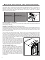
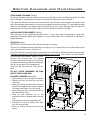
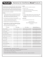
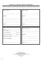
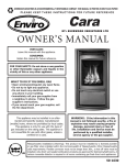
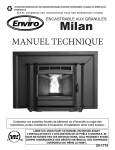
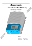
SHERWOOD INDUSTRIES IS AN ENVIRONMENTALLY RESPONSIBLE COMPANY. THIS MANUAL IS PRINTED ON RECYCLED PAPER. PLEASE KEEP THESE INSTRUCTIONS FOR FUTURE REFERENCE VF 170B PELLET STOVE OWNER’S MANUAL PLEASE READ THIS ENTIRE MANUAL BEFORE INSTALLATION AND USE OF THIS PELLET-BURNING ROOM HEATER. FAILURE TO FOLLOW THESE INSTRUCTIONS COULD RESULT IN PROPERTY DAMAGE, BODILY INJURY OR EVEN DEATH. Contact your building or fire officials about restrictions and installation inspection requirements in your area. 50-1863 Table of Contents Introduction........................................................................................3 Rating Label Location................................................................3 Pellet Quality............................................................................3 Safety Warnings & Recommendations....................................................4 Operating Instructions..........................................................................6 Dimensions & Specifications:......................................................6 Control Board Functions............................................................7 Automatic Safety Features of Your Pellet Stove............................7 Operating Your Pellet Stove........................................................7 Turning Your Pellet Stove Off:....................................................8 Slider/Damper Set-Up................................................................9 Guidelines For Fine-Tuning For Fuel Quality.................................9 Routine Cleaning and Maintenance......................................................10 Warranty...........................................................................................13 Installation Data Sheet.......................................................................14 2 Introduction * This manual is designed for the home owner in conjunction with the technical manual. * Rating Label Location: The rating label is located on the inside of the hopper. Pellet Quality: Pellet quality is important, please read the following: Your Vista Flame pellet stove has been designed to burn ¼” (6mm) dia wood pellets only. DO NOT use this appliance as an incinerator. DO NOT use unsuitable and non recommended fuels, including liquid fuels as this will void any warranties stated in this manual. The performance of your pellet stove is greatly affected by the type and quality of wood pellets being burned. As the heat output of various quality wood pellets differs, so will the performance and heat output of the pellet stove. CAUTION: It is important to select and use only pellets that are dry and free of dirt or any impurities such as high salt content. Dirty fuel will adversely affect the operation and performance of the unit and will void the warranty. The Pellet Fuel Industries (P.F.I.) has established standards for wood pellet manufacturers. We recommend the use of pellets that meet or exceed these standards. Ask your dealer for a recommended pellet type. ASH: The ash content of the fuel and operation of your stove will directly determine the frequency of cleaning. The use of high ash fuels may result in the stove needing to be cleaned daily. A low ash fuel may allow longer intervals between cleaning. CLINKERING: [clinkers are silica (sand) or other impurities in the fuel that will form a hard mass during the burning process]. This hard mass will block the air flow through the Burn Pot Liner and affect the performance of the stove. Any fuel, even approved types, may clinker. Check the Burn-Pot Liner daily to ensure that the holes are not blocked with clinkers. If they become blocked, remove the liner (when the unit is cold) and clean/scrape the clinkers out. Clean the holes with a small pointed object if required. Refer to the section Routine Cleaning and Maintenance. PELLET FEED RATES: Due to different fuel densities and sizes, pellet feed rates may vary. This may require an adjustment to the slider damper setting or to the auger feed trim setting on low. Since Sherwood Industries Ltd. has no control over the quality of pellets that you use, we assume no liability for your choice in wood pellets. FILLING FUEL HOPPER: Open lid on top of unit, check hopper for foreign objects, empty the bag into the hopper, DO NOT OVER FILL, and ensure hopper lid closes completely. Store pellets at least 36” (1 m) away from the pellet stove. WARNING: Parts of the appliance, especially the external surfaces, will be hot to touch when in operation so use due care. FLAMMABLE LIQUIDS: Never use gasoline, gasoline-type lantern fuel, kerosene, charcoal lighter fluid, or similar liquids to start or “freshen up” a fire in the heater. Keep all such liquids well away from the heater while it is in use. 3 Safety Warnings & Recommendations Please read this entire Owner’s Manual before installing or operating your Vista Flame Pellet Stove. Failure to follow these instructions may result in property damage, bodily injury or even death. Any unauthorized modification of the appliance or use of replacement parts not recommended by the manufacturer is prohibited. All national and local regulations and shall be complied with when operating this appliance. Caution: Do not connect to any air distribution duct or system. Warning: Never place wood, paper, furniture, drapes or other combustible materials within 80cm (31½”) of the front of the unit, 20cm (7⅞”) from each side, and 10cm (4”) from the back of the unit. Do not let children or pets touch it when it is hot. To prevent the possibility of a fire, ensure that the appliance is properly installed by adhering to the installation instructions. An Vista Flame dealer will be happy to assist you in obtaining information with regards to your local building codes and installation restrictions. FIRE EXTINGUISHER AND SMOKE DETECTION: All homes with a pellet burning stove should have at least one fire extinguisher in a central location known to all in the household. Smoke detectors should be installed and maintained in the room containing the stove. If it sounds the alarm, correct the cause but do not deactivate. You may choose to relocate the smoke detection devise within the room; DO NOT REMOVE THE SMOKE DETECTOR FROM THE ROOM. CHIMNEY OR RUN AWAY FIRE: Call local fire department (or dial 911). Close the draft fully. Extinguish the fire in the burn pot liner with a cup of water and close the door. Examine the flue pipes, chimney, attic, and roof of the house, to see if any part has become hot enough to catch fire. If necessary, spray with fire extinguisher or water from the garden hose. IMPORTANT: Do not operate the stove again until you are certain the chimney and its lining have not been damaged. OPERATION: The door and ash drawer must be kept closed when the unit is in operation to prevent fume spillage and for proper and safe operation of the pellet stove. Also ensure all gaskets on the door are checked and replaced when necessary. Unit hot while in operation. Keep children, clothing and furniture away. Contact may cause skin burns. CAUTION: When operating during adverse weather, if the unit exhibits dramatic changes in combustion stop using the unit immediately. FUEL: This pellet stove is designed and approved to only burn wood pellet fuel with up to 3% ash content. Dirty fuel will adversely affect the operation and performance of the unit and may void the warranty. Check with your dealer for fuel recommendations. THE USE OF CORDWOOD IS PROHIBITED BY LAW. Do not burn garbage or flammable fluids such as gasoline, naptha or engine oil. SOOT: Operation of the stove with insufficient combustion air will result in the formation of soot which will collect on the glass, the heat exchanger, the exhaust vent system, and may stain the outside of the house. This is a dangerous situation and is inefficient. Frequently check your stove and adjust the slider/damper as needed to ensure proper combustion. See: “Slider/Damper Setting”. CLEANING: There will be some build up of fly ash and small amounts of creosote in the exhaust. This will vary due to the ash content of the fuel used and the operation of the stove. It is advisable to inspect and clean the exhaust vent semi-annually or every two tons of pellets. The appliance, flue gas connector and the chimney flue require regular cleaning. Check them for blockage prior to re-lighting after a prolonged shut down period. ASHES: Disposed ashes should be placed in a metal container with a tight fitting lid. The closed container of ashes should be on a non-combustible surface, well away from all combustible materials pending final disposal. If the ashes are disposed of by burial in soil or otherwise locally dispensed, they should be retained in the closed container until all cinders have thoroughly cooled. KEEP ASH PAN FREE OF RAW FUEL. DO NOT PLACE UNBURNED OR NEW PELLET FUEL IN ASH PAN. A fire in the ash pan may occur. 4 Safety Warnings & Recommendations ELECTRICAL: The use of a surge protected power bar is recommended. The unit must be grounded. The grounded electrical cord should be connected to a standard 110-120 volts (3.6 Amps), 60 hertz electrical outlet and also must be accessible. Ensure the polarity to the outlet, the unit will be plugged into, is correct as incorrect polarity can affect the unit’s operation. If the power cord should become damaged, a replacement power cord must be purchased from the manufacturer or a qualified Vista Flame dealer. Be careful that the electrical cord is not trapped under the appliance and that it is clear of any hot surfaces or sharp edges. This unit’s maximum power requirement is 432 watts. When installing the stove in a mobile home, it must be electrically grounded to the steel chassis of the home and bolted to the floor. GLASS: Do not abuse the glass by striking or slamming the door. Do not attempt to operate the stove with broken glass. The stove uses ceramic glass. Replacement glass must be purchased from an Vista Flame dealer. Do not attempt to open the door and clean the glass while the unit is in operation or if glass is hot. To clean the glass, use a soft cotton cloth and mild window cleaner, gas or wood stove glass cleaner, or take a damp paper towel and dip into the fly ash. This is a very mild abrasive and will not damage the glass. INSTALLATION: Contact your local building or fire official to obtain a permit and any information on installation restrictions and inspection requirements for your area. Be sure to maintain the structural integrity of your home when passing a vent through walls, ceilings, or roofs, and all construction meets local building codes. It is recommended that the unit be secured into its position in order to avoid any displacement. This appliance must be installed on a floor with an adequate load bearing capacity, if existing construction doesn’t meet load capacity, suitable measures (e.g. load distributing plate) must be taken to achieve it. DO NOT INSTALL A FLUE DAMPER IN THE EXHAUST VENTING SYSTEM OF THIS UNIT. DO NOT CONNECT THIS UNIT TO A CHIMNEY FLUE SERVING ANOTHER APPLIANCE. FRESH AIR: This unit uses large quantities of air for combustion; outside Fresh Air connection is strongly recommended. Fresh Air must be connected to all units installed in Mobile and “Air Tight Homes” (R2000) or where required by local codes. Consider all large air moving devices when installing your unit and provide room air accordingly. NOTE: Extractor fans when operating in the same room or space as the appliance may cause problems. Limited air for combustion may result in poor performance, smoking and other side effects of poor combustion. The stove’s exhaust system works with negative combustion chamber pressure and a slightly positive chimney pressure. It is very important to ensure that the exhaust system be sealed and airtight. The ash pan and viewing door must be locked securely for proper and safe operation of the pellet stove. Do not burn with insufficient combustion air. A periodic check is recommended to ensure proper combustion air is admitted to the combustion chamber. Setting the proper combustion air is achieved by adjusting the slider damper located on the left side of the stove. Minor soot or creosote may accumulate when the stove is operated under incorrect conditions such as an extremely rich burn (black tipped, lazy orange flames). If you have any questions with regards to your stove or the above-mentioned information, please feel free to contact your local dealer for further clarification and comments. SINCE SHERWOOD INDUSTRIES LTD. HAS NO CONTROL OVER THE INSTALLATION OF YOUR STOVE, SHERWOOD INDUSTRIES LTD. GRANTS NO WARRANTY IMPLIED OR STATED FOR THE INSTALLATION OR MAINTENANCE OF YOUR STOVE. THEREFORE, SHERWOOD INDUSTRIES LTD. ASSUMES NO RESPONSIBILITY FOR ANY CONSEQUENTIAL DAMAGE(S). SAVE THIS INSTRUCTION MANUAL FOR FUTURE REFERENCE. 5 Operating Instructions Dimensions & Specifications: 213/4" (553mm) 157/8" (403mm) 281/4" (716mm) 223/8" (568mm) 25" (637mm) 263/4" (680mm) 233/4" (605mm) 263/8" (671mm) 417/8" (1063mm) 411/4" (1048mm) 27" (687mm) Figure 1: Dimensions of VF100. Table 1: VF100 Specifications. Testing Standard ASTM 1509-04 Frequency 60 Hz Voltage 110 - 120 V Fuel type wood pellets - 6mm (¼”) dia. Current 3.6 Amps Max Power 432 Watts Description Residential Wood Pellet Heater Hopper Capacity up to 130 lb (59 Kg) Consumption on Low 1.7 lb/hr (0.77 Kg/hr)* Weight (with full hopper) 455 lb (206 Kg) Consumption on High 7.6 - 8.3 lb/hr (3.45-3.76 Kg/hr)* *Note: Consumption will vary with the type of fuel used. 6 Operating Instructions Control Board Functions: 1. AUGER LIGHT: This green light will flash in conjunction with the auger pulse. 2. MODE LIGHT: Responsible for signaling the state of the control board. When the light is flashing the stove is in an automatic start mode or the thermostat has control of the unit. When the light is solid, the Heat Level Setting can be altered. 3. THERMOSTAT SWITCH: Used to set the unit’s controls to one of three mode settings; manual, high/low, or auto/off. 4. FEED RATE TRIM BUTTON: Used to change the feed rate trims in ¼ second increments for all feed settings. When this button is pressed, all the light will light up on the Heat Output Indicator except for the one that shows the current setting; the default setting is the number 4 light. To adjust 1 AUGER the setting hold the Feed RateAUGER Trim button down and press the Heat Level up or down buttons to adjust the setting. MODE MODE 2 9 5. COMBUSTION BLOWER TRIM BUTTON: Used to change the Combustion Blower trims in 5 volt increments for all feed settings 3 until it reaches line voltage. When this button is pressed, all the light will light up on the Heat Output Indicator except for the one that 4 shows the current setting; the default FEED RATE FEED RATE setting is the number 2 light. HEAT LEVEL HEAT LEVEL 8 TRIM TRIM To adjust the setting hold the Combustion Blower Trim button down 5 and press the Heat Level up or down buttons to adjust the setting. COMBUSTION COMBUSTION BLOWER TRIM BLOWER TRIMunit ON and OFF. 6. ON/OFF BUTTON: Used to turn the 6 7. ROOM AIR FAN ON/OFF BUTTON: Used to turn convection fan 7 ROOM AIR ON/OFF ROOM AIR ON/OFF on or off. FAN ON/OFF FAN ON/OFF 8. HEAT LEVEL ADJUSTMENT BUTTONS: When pressed, will change the heat level setting of the unit up or down. C-11625 C-11625 9. HEAT OUTPUT INDICATOR: Shows the present heat output setting. Figure 3: Circuit Board Control AUTO/OFF AUTO/OFF HIGH/LOW HIGH/LOW MANUAL MANUAL Panel Decal. Automatic Safety Features of Your Pellet Stove: A. The stove will shut off when the fire goes out and the exhaust temperature drops below 120°F (49°C). B. The stove has a high temperature safety switch. If the temperature on the hopper reaches 200°F (93°C), the auger will automatically stop and the stove will shut down when the exhaust temperature cools #4 light flashes. Dealer will have to reset the sensor. If this happens, call your local dealer to reset the 200°F (93°C) high limit switch. ALSO FIND THE REASONS WHY THE UNIT OVERHEATED. C) The unit is equipped with a vacuum switch to monitor the venting; if it becomes blocked the vacuum switch will turn off the auger and the #2 light on the control board will flash. Operating Your Pellet Stove: PRE-BURN INSTRUCTIONS: The burn pot liner holes must be clear and the liner installed properly against the ignitor tube for proper operation. Check the hopper for enough pellets to start the unit. DO NOT OPERATE THE UNIT WITH THE DOOR OR ASH PAN OPEN. Note: The thermostat mode can be changed during normal operation. 7 Operating1 Instructions AUGER AUGER MANUAL MODE: MODE MODE 2 9 circuit board function is adjusted at the circuit board. All control of AUTO/OFF AUTO/OFF To START: Press the ON / OFF button. The stove will turn on. The HIGH/LOW HIGH/LOW 3 system light will flash. The Auger Light will flash with each pulse of the MANUAL MANUAL auger (the Auger Feed Rate is pre-programmed during start-up). The Heat Level Indicator will show the Heat Level 4that the stove will run at after start-up and can be adjusted but the change will not take affect Figure 4: ThermostatFEED Switch FEED RATE RATE in HEAT LEVEL HEAT LEVEL until the start has finished. 8 -up TRIM TRIM MANUAL position. If this is the first time the unit has been started or the unit has run out 5 of fuel, the auger will need to be primed. This can be done by restarting the unit five (5) minutes into its COMBUSTION COMBUSTION start-up or by putting a small hand full TRIM of pellets into the burnpot. BLOWER BLOWER TRIM To OPERATE: When a fire has been established, the System Light will turn solid (after approximately 10 6 7 - 15 minutes) and the Auger Light will continue to flash to the corresponding Heat Level setting. ROOM AIR ON/OFF ROOM AIR ON/OFF The convection blower (room air blower) will turn on. The speed of this blower controlled by the setting FAN ON/OFF FANis ON/OFF of the heat level output indicator. The convection blower can be turned OFF by depressing the convection 1 convection blower should be left on at allAUGER AUGERefficiency the blower control button. For the best times. HIGH/LOW MODE: (Requires MODE a thermostat) C-11625 2 9 INITIAL START-UP: See manual mode above. AUTO/OFF OPERATION: When the thermostat calls for heat (contacts are closed) HIGH/LOW 3 the stove settings are adjustable When the MANUAL as per Manual Mode. thermostat contacts open, the HEAT LEVEL and Fans will drop down to the LOW setting until the thermostat contacts4close again. *The LOW heat setting can be adjusted for different FEED RATE fuel qualities (see “Operating 1 AUGER HEAT LEVEL TRIM Instructions8 - Control Board Functions ”). The stove will come back to the previous HEAT LEVEL setting when the thermostat contacts close 5 MODE 2 again. 9 COMBUSTION BLOWER AUTO/OFF MODE C-11625 AUTO/OFF HIGH/LOW MANUAL Figure 5: ThermostatFEED Switch RATE in AUGER HEAT LEVEL TRIM HIGH/LOW position. MODE COMBUSTION TRIM TRIM BLOWER AUTO/OFF AUTO/OFF MODE: (RequiresHIGH/LOW a thermostat) 3 HIGH/LOW 6 7 MANUAL MANUAL INITIAL START-UP: See manual mode above. ROOM AIR ON/OFF ROOM AIR ON/OFF OPERATION: When the thermostat contacts close, the unit will light FAN ON/OFF FAN ON/OFF 4 automatically. Once up to temperature, the stove operates the same Figure 6: ThermostatFEED Switch FEED RATE RATE in as in MANUAL. When the thermostat contacts open, the stove’s HEAT HEAT LEVEL HEAT LEVEL 8 ON/OFF position. TRIM TRIM LEVEL and Fans will drop down to the LOW setting for 30 minutes. If 5 C-11625 C-11625 the thermostat contacts close within the 30 minutes, the HEAT LEVEL will return to the previous MANUAL COMBUSTION COMBUSTION setting. If the thermostat contacts remain open the stove automatically begins its shutdown routine. The BLOWER TRIM BLOWER TRIM ON / OFF button can be presses at any time the the stove will immediately shut down. The stove will relight when 7the thermostat contacts close again. 6 ROOM AIR FAN ON/OFF Turning Your P ellet Stove Off: ON/OFF ROOM AIR FAN ON/OFF ON/OFF • MANUAL and HI / LOW mode: To turn the unit OFF, simply press the ON / OFF button. This will stop the feed of pellets. The blowers will continue to operate and cool the stove down. When cool enough, C-11625 C-11625 the stove will turn off. • AUTO / OFF mode: To turn the unit OFF, turn the thermostat down or off. NOTE: The unit will run on low for three (3) minutes before it turns off. DO NOT unplug unit while Combustion fan is operating. This may lead to smoke escaping from the stove. 8 Operating Instructions Slider/Damper Set-Up: THE SLIDER / DAMPER MUST BE SET AT TIME OF INSTALLATION. A Qualified Service Technician or Installer must set the Slider Damper. If the fire should happen to go out and the heat output indicator has been set on the lowest setting, the Slider Damper should be pushed in slightly, decreasing the air in the firebox. If, after long periods of burning, the fire builds up and overflows the burn pot or there is a build up of clinkers, this would be a sign that the pellet quality is poor, this requires more primary air, the slider damper must be pulled out to compensate. Pulling the slider damper out gives the fire more air. The easiest way to make sure that an efficient flame is achieved is to understand the characteristics of the fire. • A tall, lazy flame with dark orange tips requires more air – Open slider (pull out) slightly. • A short, brisk flame, like a blowtorch, has too much air – Close slider (push in) slightly. • If the flame is in the middle of these two characteristics with a bright yellow/ orange, active flame with no black tips then the air is set for proper operation, refer to Figure 7. Exhaust Channel Exhaust Fan Housing Slider Damper Figure 6: Slider/Damper Plate in Unit. The combustion exhaust blower is a variable speed blower controlled by the heat output button. This blower will decrease the vacuum pressure inside the stove, adjusting the air to fuel ratio. Figure 7: Efficient Flame. SPECIAL NOTES: Pellet quality is a major factor in how the Pellet stove will operate. If the pellets have a high moisture content or ash content the fire will be less efficient and has a higher possibility of the fire building up and creating clinkers (hard ash build-up). Guidelines For Fine-Tuning For Fuel Quality: Due to fuel quality the slider damper and control board trims may need to be fine-tuned. 1.If the unit builds up on all settings, the slider damper rod should be pulled out in small increments to give the unit more air. 2.If the unit has excesses ash build-up in the liner on the lower feed settings, the Combustion Blower Trim should be increased one setting at a time until the problem improves (Factory Setting is #2). 3.If the fire is going out on low because the airflow is too great, the Combustion Blower Trim can be lowered to the #1 setting. 4.If the stove has excesses ash build-up in the liner on the higher settings the Feed Rate Trim should be trimmed down a setting at a time until the problem improves (Factory setting is #4). 5.If you need more heat and the fuel has long pellets, the majority are over 1” (2.5cm) in length, the Feed Rate Trim can be moved up to the #5 setting. NOTE: Only do this if the fuel burns without building up. 9 Routine Cleaning and Maintenance The following list of components should be inspected and maintained routinely to ensure that the appliance is operating at its optimum and giving you excellent heat value. The appliance, flue gas connector and the chimney flue require regular cleaning. Check them for blockage prior to re-lighting after a prolonged shut down period. Check the Burn Pot Liner DAILY Weekly Bi-annually or 2 Tons of Fuel Burn Pot and Liner - Empty Exhaust Vent Heat Exchanger Tubes Fresh Air Intake Tube Ash Box Blower Mechanisms Door Glass Heat Exchanger Tubes Inside Firebox Behind Firebox Liners Ash Pan and Door Gaskets All Hinges Door Latch Post Season Clean-up Burn Pot Liner Ignitor Air Intake Tube Burn Pot Figure 8: VF100 Burn pot and Liner TOOLS REQUIRED TO CLEAN UNIT: Torx T-20 Screwdriver, ¼”, 5/16” ⅜”, & 7/16” wrench and/or socket, Ash Pan Tool, Brush, Soft Cloth, and Vacuum with fine filter bag BURNER POT AND LINER (Checked Daily/Emptied Weekly) To remove the burn pot and burn pot liner, open the door using the door handle provided (located on the right-hand side of the stove). Swing the door open. Lift the liner from the burn pot. Lift the burn pot from the firebox by gently lifting up the front of the burn pot, then sliding the assembly from the air intake tube and the ignitor cartridge. This is the ‘pot’ where the pellets are burned. When the unit is cold, remove the burn-pot liner from the stove. Using a metal scrapper, remove material that has accumulated or is clogging the liner’s holes. Then dispose of the scrapped ashes from the liner and from inside the burn-pot. Place the burn-pot back into the stove, making sure that the pipes are properly inserted into the burn pot. Place the liner back into the burn-pot, making sure that the ignitor hole in the liner is aligned with the ignitor tube; push the liner up against the ignitor tube. If, after long periods of burning, the fire continually builds up and overflows the burn pot or there is a build up of clinkers, this is an indication that the pellet fuel quality is poor or the stove may need cleaning. Check the stove for ash build up (clean if required) and adjust the slider / damper to produce the proper clean combustion. HEAT EXCHANGER TUBES (Weekly) There are two (2) sets of exchanger tube scrapers; the handles are located under the top grill (trivet). Lift the grill and move the handles all the way up and down a few times (ONLY WHEN THE UNIT IS COLD) in order to clean away any fly ash that may have collected on the heat exchanger tubes. As different types of pellets produce different amounts of ash, cleaning of the tubes should be done on a regular basis to enable the unit to run efficiently. 10 Figure 9: VF100 Burn Heat Exchanger Cleaning. Routine Cleaning and Maintenance DOOR GLASS CLEANING (Weekly) Cleaning of the glass must only be done when stove is cold. Open the door by lifting the handle. The glass can be cleaned by wiping down the outside and inside of the glass with a dry soft cloth. If the glass has build up that can not be removed with only the cloth, clean the glass using paper towel and a gas appliance glass cleaner, this may be purchased through most dealers. If a gas appliance glass cleaner is not available, use a damp paper towel dipped in fly ash to clean the glass. After the glass has been cleaned use the dry soft cloth to wipe down the outside and inside of the glass. ASH PAN AND DOOR GASKETS (Weekly) After extended use the gasketing may come loose. To repair this, glue the gasketing on using hightemperature fiberglass gasket glue available from your local dealer. This is important to maintain an airtight assembly. ASH BOX (Weekly) IMPORTANT: The unit must be OFF while the ash pan is removed. The ash box is located behind the lower door (see Figure 10). To remove the ash box, lift the latch on the right, open the ash box door, and lift it out. Dump the ashes into a metal container stored away from combustibles. Monitor the ash level every week. Remember that different pellet fuels will have different ash contents. Ash content is a good indication of fuel efficiency and quality. Refer to “Safety Warnings And Recommendations” for disposal of ashes. Vacuum the inside of the ash pan compartment inside the pedestal including the hole at the top back of the compartment. Insert the ash box fully and close ash box door. DO NOT PLACE UNBURNED OR RAW PELLET FUEL IN ASH PAN. EXHAUST PASSAGES (Biannually) • Open the firebox door by lifting the handle. • Remove the burn pot and burn pot liner; clean both. • Using a ⅜” socket, remove the two (2) bolts that hold the firebox liner in place. Vacuum the firebox and firebox liner thoroughly. • Open the ash box door; remove the ash box and cleanout the cavity. • Clean out the transition box to the combustion blower (located behind the ash box) • Lubricate all screws with penetrating oil. • Re-install the ash box, firebox liner, burn pot, and burn pot liner • Close the firebox and ash pan doors and secure. Firebox Liner Burn Pot Liner Burn Pot Ash Box Figure 10: VF100 Exhaust Passages. 11 Routine Cleaning and Maintenance EXHAUST VENT (Biannually) This vent should be cleaned every year or after two tons of pellets. We recommend contacting your dealer for professional cleaning. To clean the vent pipe, tap lightly on the pipe to dislodge any loose ash. Open the bottom of the “T” to dump the ash, then vacuum as much of the ash out of the vent pipe as possible. FRESH AIR INTAKE (Biannually) Inspect periodically to be sure that it is not clogged with any foreign materials. BLOWER MECHANISMS (Annually) Unplug the stove then open the right and left side panels to access the two blowers. Remove the two (2) T-20 Torx screws on the back of the each panel. Pull the bottom of the panel out then slide the top of the panel down off the tab. Vacuum all dust from motors. The blower motors’ has sealed bearings, DO NOT lubricate this motor. Check gaskets and replace if needed. POST SEASON CLEAN-UP Once you are finished using the pellet appliance for the season, unplug the stove for added electrical protection. It is very important that the stove be cleaned and serviced as stated above. CLEANING PAINTED SURFACES Please clean painted surfaces with a soft damp cloth. FIREBOX LINER The paint on the Firebox Liner may peel. This is due to extreme conditions applied to the paint and is in no way covered by warranty. DOOR GLASS REPLACEMENT It is recommended that your dealer replace the glass if broken. The door glass is made of high temperature PYRO CERAMIC. To replace the glass, unscrew and remove the four (4) retainer nuts 7/16” socket. Remove the two (2) T-20 screws holding the inner door to the glass retainer. Remove the glass and any broken pieces. High temperature fiberglass tape should be used around the glass in the same location as the original fiberglass. Insert the glass into the retainer, screw the inner door to the retainer, install inner door assembly into outer door and gently tighten nuts. The use of substitute materials is prohibited: Glass (9” x 13” [229mm x 330mm]); EF-061. 12 Warranty for VistaFlame Wood Products Sherwood Industries Ltd. (“Sherwood”) hereby warrants, subject to the terms and conditions herein set forth, this product against defects in material and workmanship during the specified warranty period starting from the date of original purchase at retail. In the event of a defect of material or workmanship during the specified warranty period, Sherwood reserves the right to make repairs or to assess the replacement of a defective product at Sherwood’s factory. The shipping costs are to be paid by the consumer. All warranties by Sherwood are set forth herein and no claim shall be made against Sherwood on any oral warranty or representation. Exclusions Conditions To the Dealer A completed warranty registration must be submitted to Sherwood within 90 days of original purchase via the online warranty registration page or via the mail-in warranty registration card provided. Have the installer fill in the installation data sheet in the back of the manual for warranty and future reference. This warranty applies only to the original owner in the original location. The unit must have been properly installed by a qualified technician or installer, and must meet all local and national building code requirements. An expanded list of exclusions is available at www.vistaflame.ca This warranty does not cover: Damage as a result of improper usage or abuse. Damage caused from over-firing due to incorrect setup or tampering. Damage caused by incorrect installation. Provide name, address and telephone number of purchaser and date of purchase. Provide date of installation. Name of installer and dealer. Serial number of the appliance. Nature of complaint, defects or malfunction, description and part # of any parts replaced. To the Distributor Sign and verify that work and information are correct. The warranty does not cover removal and re-installation costs. Sherwood Industries Ltd. reserves the right to make changes without notice. Sherwood Industries Ltd. and its employees or representatives will not assume any damages, either directly or indirectly caused by improper usage, operation, installation, servicing or maintenance of this appliance. Sherwood Industries Ltd. 6782 Oldfield Road, Victoria, BC . Canada V8M 2A3 www,vistaflame.ca A proof of original purchase must be provided by you or the dealer. Category One Year Two Year Limited Lifetime (7yr) Secondary Air Tubes Surround Panels (excluding finish) Pedestals / Legs (excluding finish) Ceramic Glass 4 Door Assembly Slider Control Shield Assembly (No labour after 3 years) Electrical Components Parts 1 & Labour Firebox (excluding bricks) Ceramic Baffle 2 3 Convection Fan Exterior Surface Finishing 5 1 Second replacement part – 1 year, labour not included 2 Warranty does not cover damage caused from burning artificial/firestarter log varieties. 3 Excludes damage caused by loading wood, cleaning or service 4 Glass is covered only for thermal breakage 5 Exterior Surface finishing covers Plating, Enamel or Paint and excludes colour changes, chipping, and fingerprints February 2012 13 Installation Data Sheet The following information must be recorded by the installer for warranty purposes and future reference. NAME OF OWNER: NAME OF DEALER: _________________________________________ _________________________________________ ADDRESS: ADDRESS: _________________________________________ _________________________________________ _________________________________________ _________________________________________ _________________________________________ _________________________________________ PHONE:___________________________________ PHONE:___________________________________ MODEL:___________________________________ SERIAL NUMBER:___________________________ DATE OF PURCHASE: _____________ NAME OF INSTALLER: _________________________________________ (dd/mm/yyyy) DATE OF INSTALLATION:___________(dd/mm/yyyy) MAGNEHELIC AT INSTALL:___________________ ADDRESS: _________________________________________ _________________________________________ INSTALLER’S SIGNATURE: _________________________________________ _________________________________________ PHONE:___________________________________ MANUFACTURED BY: SHERWOOD INDUSTRIES LTD. 6782 OLDFIELD RD. SAANICHTON, BC, CANADA V8M 2A3 February 17, 2012 C-12171 14