1
R-410A
XP SERIES
3 - 5 Ton
60 Hertz
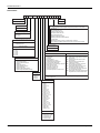
TABLE OF CONTENTS
General . . . . . . . . . . . . . . . . . . . . . . . . . . . . . . . . . . . . . . . . . . 2
Installation . . . . . . . . . . . . . . . . . . . . . . . . . . . . . . . . . . . . . . . . 5
Installation Safety Information. . . . . . . . . . . . . . . . . . . . . . . 5
Limitations . . . . . . . . . . . . . . . . . . . . . . . . . . . . . . . . . . . . . . 5
Location. . . . . . . . . . . . . . . . . . . . . . . . . . . . . . . . . . . . . . . . 6
Rigging And Handling . . . . . . . . . . . . . . . . . . . . . . . . . . . . . 7
Ductwork . . . . . . . . . . . . . . . . . . . . . . . . . . . . . . . . . . . . . . 12
Condensate Drain . . . . . . . . . . . . . . . . . . . . . . . . . . . . . . . 12
Compressors. . . . . . . . . . . . . . . . . . . . . . . . . . . . . . . . . . . 12
Filters . . . . . . . . . . . . . . . . . . . . . . . . . . . . . . . . . . . . . . . . 13
Power And Control Wiring. . . . . . . . . . . . . . . . . . . . . . . . . 13
Optional Electric Heat . . . . . . . . . . . . . . . . . . . . . . . . . . . . 29
Options/Accessories . . . . . . . . . . . . . . . . . . . . . . . . . . . . . 29
Economizer And Power Exhaust Set Point Adjustments .
Checking Supply Air CFM . . . . . . . . . . . . . . . . . . . . . . . . .
Operation . . . . . . . . . . . . . . . . . . . . . . . . . . . . . . . . . . . . . . .
Sequence Of Operation . . . . . . . . . . . . . . . . . . . . . . . . . .
No Outdoor Air Options . . . . . . . . . . . . . . . . . . . . . . . . .
Cooling Operation Errors . . . . . . . . . . . . . . . . . . . . . . . .
Heating Sequence Of Operations . . . . . . . . . . . . . . . . . . .
Start-up (Cooling) . . . . . . . . . . . . . . . . . . . . . . . . . . . . . . . . .
Troubleshooting . . . . . . . . . . . . . . . . . . . . . . . . . . . . . . . . . .
Fan On And Off Delays . . . . . . . . . . . . . . . . . . . . . . . . . . .
Maintenance . . . . . . . . . . . . . . . . . . . . . . . . . . . . . . . . . . . . .
Normal Maintenance . . . . . . . . . . . . . . . . . . . . . . . . . . . . .
29
37
38
38
38
39
40
41
42
44
44
44
LIST OF TABLES
1
2
3
4
5
6
7
8
9
10
XP036-060 Unit Limitations . . . . . . . . . . . . . . . . . . . . . . . 6
Weights and Dimensions . . . . . . . . . . . . . . . . . . . . . . . . . 8
XP036-060 Unit Accessory Weights . . . . . . . . . . . . . . . . 8
XP036-060 Unit Clearances . . . . . . . . . . . . . . . . . . . . . . 10
XP036-060 Utilities Entry . . . . . . . . . . . . . . . . . . . . . . . . 11
Control Wire Sizes . . . . . . . . . . . . . . . . . . . . . . . . . . . . . 14
Electrical Data . . . . . . . . . . . . . . . . . . . . . . . . . . . . . . . . 15
XP036-060 Physical Data . . . . . . . . . . . . . . . . . . . . . . . 27
Electric Heat Minimum Supply Air . . . . . . . . . . . . . . . . . 29
Altitude/Temperature Correction Factors . . . . . . . . . . . . 32
11
12
13
14
15
16
17
18
19
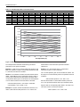
XP Blower Performance Side Duct . . . . . . . . . . . . . . . .
XP Blower Performance Bottom Duct . . . . . . . . . . . . . .
Belt Drive RPM Selection . . . . . . . . . . . . . . . . . . . . . . . .
Indoor Blower Specifications (Belt Drive) . . . . . . . . . . . .
Power Exhaust Specifications . . . . . . . . . . . . . . . . . . . .
Additional Static Resistance . . . . . . . . . . . . . . . . . . . . . .
Electric Heat Limit Setting . . . . . . . . . . . . . . . . . . . . . . .
Electric Heat Anticipator Setpoints . . . . . . . . . . . . . . . . .
Unit Control Board Flash Codes . . . . . . . . . . . . . . . . . .
34
35
36
36
37
38
41
41
44
LIST OF FIGURES
1
2
3
4
5
XP036-060 Component Location . . . . . . . . . . . . . . . . . 6
Unit 4 Point Load Weight . . . . . . . . . . . . . . . . . . . . . . . 8
Unit 6 Point Load Weight . . . . . . . . . . . . . . . . . . . . . . . 8
Center of Gravity . . . . . . . . . . . . . . . . . . . . . . . . . . . . . . 8
XP036-060 Heat Pump/Electric Heat Front View Physical
Dimensions . . . . . . . . . . . . . . . . . . . . . . . . . . . . . . . . . . . 9
6 XP036-060 Fixed Outdoor Air Motorized Damper Rain
Hood Physical Dimensions . . . . . . . . . . . . . . . . . . . . . . 10
7 XP036-060 Disconnect Location . . . . . . . . . . . . . . . . . 10
8 XP036-060 Unit Side Duct Openings . . . . . . . . . . . . . 11
9
10
11
12
13
14
15
16
17
18
XP036-060 Roof Curb . . . . . . . . . . . . . . . . . . . . . . . . .
Condensate Drain . . . . . . . . . . . . . . . . . . . . . . . . . . . .
Compressor Restraining Bracket . . . . . . . . . . . . . . . .
Typical Field Power and Control Wiring . . . . . . . . . . .
Enthalpy Set Point Chart . . . . . . . . . . . . . . . . . . . . . . .
Honeywell Economizer Control W7212 . . . . . . . . . . . .
Belt Adjustment . . . . . . . . . . . . . . . . . . . . . . . . . . . . . .
Altitude/Temperature Correction Factors . . . . . . . . . .
Pressure Drop Across Coil . . . . . . . . . . . . . . . . . . . . .
Unit Control Board . . . . . . . . . . . . . . . . . . . . . . . . . . . .
11
12
13
14
30
30
31
32
37
44
444463-YIM-D-0311
444463-YIM-D-0311
General
YORK® Model XP units are single package heat pumps
equipped with optional factory installed electric heaters. These
units are designed for outdoor installation on a rooftop or slab.
The units are completely assembled on rigid, permanently
attached base rails. All piping, refrigerant charge, and electrical
wiring is factory installed and tested. The units require electric
power, duct connections and fixed outdoor air intake damper
(units without economizer or motorized damper option only) at
the point of installation.
Before performing service or maintenance operations on
unit, turn off main power switch to unit. Electrical shock
could cause personal injury. Improper installation,
adjustment, alteration, service or maintenance can
cause injury or property damage. Refer to this manual.
For assistance or additional information consult a
qualified installer or service agency.
The supplemental electric heaters have nickel-chrome
elements and utilize single point power connection.
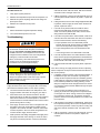
Safety Considerations
This is a safety alert symbol. When you see this symbol on
labels or in manuals, be alert to the potential for personal injury.
Understand and pay particular attention the signal words
DANGER, WARNING or CAUTION.
DANGER indicates an imminently hazardous situation, which,
if not avoided, will result in death or serious injury.
WARNING indicates a potentially hazardous situation, which,
if not avoided, could result in death or serious injury.
CAUTION indicates a potentially hazardous situation, which, if
not avoided may result in minor or moderate injury. It is also
used to alert against unsafe practices and hazards involving
only property damage.
Improper installation may create a condition where the
operation of the product could cause personal injury or
property damage. Improper installation, adjustment,
alteration, service or maintenance can cause injury or
property damage. Refer to this manual for assistance or
for additional information, consult a qualified contractor,
installer or service agency.
This system uses R-410A Refrigerant which operates at
higher pressures than R-22. No other refrigerant may be
used in this system. Gage sets, hoses, refrigerant
containers and recovery systems must be designed to
handle R-410A. If you are unsure, consult the equipment
manufacturer. Failure to use R-410A compatible servicing
equipment may result in property damage or injury.
Due to system pressure, moving parts, and electrical
components, installation and servicing of air conditioning
equipment can be hazardous. Only qualified, trained service
personnel should install, repair, or service this equipment.
Untrained personnel can perform basic maintenance functions
of cleaning coils and filters and replacing filters.
Observe all precautions in the literature, labels, and tags
accompanying the equipment whenever working on air
conditioning equipment. Be sure to follow all other applicable
safety precautions and codes that apply.
Wear safety glasses and work gloves. Use quenching cloth and
have a fire extinguisher available during brazing operations.
Inspection
As soon as a unit is received, it should be inspected for possible
damage during transit. If damage is evident, the extent of the
damage should be noted on the carrier’s freight bill. A separate
request for inspection by the carrier’s agent should be made in
writing.
Reference
This product must be installed in strict compliance with
the installation instructions and any applicable local,
state and national codes including, but not limited to
building, electrical, and mechanical codes.
2
Additional information is available in the following reference
forms:
• Technical Guide - ZJ036-060 / XP036-060, 251933
• General Installation - XP036-060, 362251
Johnson Controls Unitary Products
444463-YIM-D-0311
Renewal Parts
Contact your local York® parts distribution center for authorized
replacement parts.
Approvals
Design certified by CSA as follows:
1.
For use as a heat pump only with or without optional
electric heat.
2.
For outdoor installation only.
3.
For installation on combustible material.
Improper installation may create a condition where the
operation of the product could cause personal injury or
property damage.
This system uses R-410A Refrigerant which operates at
higher pressures than R-22. No other refrigerant may be
used in this system.
This product must be installed in strict compliance with
the enclosed installation instructions and any applicable
local, state, and national codes including, but not limited
to, building, electrical, and mechanical codes.
Johnson Controls Unitary Products
3
444463-YIM-D-0311
Nomenclature
X P 048 C00 A 2 A AA 1 0 1 2 4 A
Product Category
Product Style
A = Style A
X = HP, Single Pkg., R-410A
Product Identifier
Configuration Options (not required for all units)
These four digits will not be assigned until a quote is requested, or an order placed.
P = 13.0 SEER HP
SS Drain Pan
CPC Controller, DFS, APS
Johnson Controller, DFS, APS
Nominal Cooling Capacity
Honeywell Controller, DFS, APS
036 = 3.0 Ton
048 = 4.0 Ton
060 = 5.0 Ton
Novar Controller, DFS, APS
Simplicity IntelliComfort Controller
Simplicity IntelliComfort Controller w/ModLinc
2" Pleated filters
Heat Type and Nominal Heat Capacity
BAS Ready Economizer (2-10 V.D.C. Actuator without a Controller)
Any Combination of Additional Options that Don’t Have an Option Code Pre-assigned
C00 = Cooling Only. Suitable for Field
Installed Electric Heat
Product Generation
Electric Heat Options
1 = First Generation
E05 = 5 KW
E07 = 7 KW
E10 = 10 KW
E15 = 15 KW
E20 = 20 KW
E30 = 30 KW
Additional Options
Airflow
A = Direct Drive
B = Direct Drive/Economizer
D = Direct Drive/Motorized Damper
N = Belt Drive
P = Belt Drive/Economizer
R = Belt Drive/Motorized Damper
T = Belt Drive High Static
U = Belt Drive High Static/Economizer
V = Belt Drive High Static/Motorized Damper
Standard Cabinet
Hinged Filter Door & Toolless Access Cabinet
AA = None
AB = Phase Monitor
AC = Coil Guard
AD = Dirty Filter Switch
AE = Phase Monitor & Coil Guard
AF = Phase Monitor & Dirty Filter Switch
AG = Coil Guard & Dirty Filter Switch
AH = Phase Monitor, Coil Guard & Dirty Filter Switch
AS = Bottom Drain Connection
RC = Coil Guard & American Flag
TA = Technicoat Condenser Coil
TJ = Technicoat Evaporator Coil
TS = Technicoat Evaporator and Condenser Coil
BA = Hinged Filter Door & Toolless Access Panels
BB = Phase Monitor, Hinged Filter Door & Toolless
Access Panels
BC = Coil Guard, Hinged Filter Door & Toolless
Access Panels
BD = Dirty Filter Switch, Hinged Filter Door &
Toolless Access Panels
BE = Phase Monitor & Coil Guard, Hinged Filter
Door & Toolless Access Panels
BF = Phase Monitor & Dirty Filter Switch, Hinged
Filter Door & Toolless Access Panels
BG = Coil Guard & Dirty Filter Switch, Hinged Filter
Door & Toolless Access Panels
BH = Phase Monitor, Coil Guard & Dirty Filter Switch,
Hinged Filter Door & Toolless Access Panels
Voltage
1 = 208/230-1-60
2 = 208/230-3-60
4 = 460-3-60
5 = 575-3-60
ZZ = If desired option combination is not listed above, ZZ will be assigned and configuration options will be
located in digits 15-18.
Installation Options
A = No Options Installed
B = Option 1
C = Option 2
D = Options 1 & 2
E = Option 3
F = Option 4
G = Options 1 & 3
H = Options 1 & 4
J = Options 1, 2 & 3
K = Options 1, 2, & 4
L = Options 1,3 & 4
M = Options 1, 2, 3, & 4
N = Options 2 & 3
P = Options 2 & 4
Q = Options 2, 3, & 4
R = Options 3 & 4
S = Option 5
T = Options 1 & 5
U = Options 1, 3, & 5
V = Options 1, 4, & 5
W = Options 1, 3, 4, & 5
X = Options 3 & 5
Y = Options 4 & 5
Z = Options 3, 4 & 5
Options
1 = Disconnect
2 = Non-Pwr'd Conv. Outlet
3 = Smoke Detector S.A.
4 = Smoke Detector R.A.
5 = Pwr'd Conv. Outlet
4
Johnson Controls Unitary Products
444463-YIM-D-0311
Installation
In U.S.A.:
1.
National Electrical Code, ANSI/NFPA No. 70 - Latest
Edition
Read these instructions before continuing this appliance
installation. This is an outdoor combination heating and cooling
unit. The installer must assure that these instructions are made
available to the consumer and with instructions to retain them
for future reference.
2.
Local building codes
3.
Local utility requirements
1.
Canadian Electrical Code, CSA C22.1
1.
Install this unit only in a location and position as specified
on Page 6 of these instructions.
2.
Local plumbing and waste water codes
2.
This equipment is not to be used for temporary heating of
buildings or structures under construction.
3.
Other applicable local codes.
Installation Safety Information
3.
If a factory option convenience outlet is installed, the
weatherproof outlet cover must be field installed. The cover
shall be located behind the blower access panel. To install
the cover, remove the shipping label covering the
convenience outlet and attach the cover to the unit using
the (4) screws provided.
In Canada:
Refer to unit application data found in this document.
If components are to be added to a unit to meet local codes,
they are to be installed at the dealer’s and/or customer’s
expense.
Size of unit for proposed installation should be based on heat
loss/heat gain calculation made according to the methods of Air
Conditioning Contractors of America (ACCA).
This unit is not to be used for temporary heating of buildings or
structures under construction.
208/230-3-60 and 380/415-3-50 units with factory
installed Powered Convenience Outlet Option are wired
for 230v and 415v power supply respectively. Change
tap on transformer for 208-3-60 or 380-3-50 operation.
See unit wiring diagram.
Limitations
These units must be installed in accordance with the following:
Johnson Controls Unitary Products
The Simplicity® control board used in this product will
effectively operate the cooling system down to 0°F when
this product is applied in a comfort cooling application
for people. An economizer is typically included in this
type of application. When applying this product for
process cooling applications (computer rooms,
switchgear, etc.), please reference applications bulletin
AE-011-07 or call the applications department for
Unitary Products @ 1-877-UPG-SERV for guidance.
Additional accessories may be needed for stable
operation at temperatures below 30° F.
5
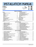
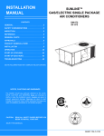
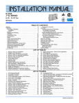
444463-YIM-D-0311
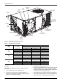
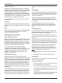
Knockout
for side
power entry
HACR
breaker
Belt drive or
Direct drive
blower
High efficiency
compressor
Economizer
hood
Copper tube/
aluminum fin
condensing coil
Slide-in
economizer
Smoke
detector
Full perimeter baserails
with forklift slots and
lifting holes
3/4" PVC female
condensate drain
Electric Heat
accessory location
GFCI
convenience outlet
Simplicity® Lite™
control board
Knockout
for side
control entry
Figure 1: XP036-060 Component Location
Table 1:
XP036-060 Unit Limitations
Unit Limitations
Size
(Tons)
036
(3.0)
048
(4.0)
060
(5.0)
Unit Voltage
Applied Voltage
Outdoor DB Temp
Min
Max
Max (°F)
208/230-1-60
187
252
125
208/230-3-60
187
252
125
460-3-60
432
504
125
575-3-60
540
630
125
208/230-1-60
187
252
125
208/230-3-60
187
252
125
460-3-60
432
504
125
575-3-60
540
630
125
208/230-1-60
187
252
125
208/230-3-60
187
252
125
460-3-60
432
504
125
575-3-60
540
630
125
Location
3.
Suitable for mounting on roof curb.
Use the following guidelines to select a suitable location for
these units:
4.
For ground level installation, use a level concrete slab with
a minimum thickness of 4 inches. The length and width
should be at least 6 inches greater than the unit base rails.
Do not tie slab to the building foundation.
5.
Roof structures must be able to support the weight of the
unit and its options/accessories. Unit must be installed on a
solid, level roof curb or appropriate angle iron frame.
1.
Unit is designed for outdoor installation only.
2.
Condenser coils must have an unlimited supply of air.
Where a choice of location is possible, position the unit on
either north or east side of building.
6
Johnson Controls Unitary Products
444463-YIM-D-0311
6.
Maintain level tolerance to 1/2” across the entire width and
length of unit.
Clearances
All units require particular clearances for proper operation and
service. Installer must make provisions for adequate ventilation
air. Refer to Table 4 for clearances required for construction,
servicing, and proper unit operation.
Do not permit overhanging structures or shrubs to
obstruct condenser air discharge outlet.
Rigging And Handling
Exercise care when moving the unit. Do not remove any
packaging until the unit is near the place of installation. Rig the
unit by attaching chain or cable slings to the lifting holes
provided in the base rails. Spreader bars, whose length
exceeds the largest dimension across the unit, MUST be used
across the top of the unit.
If a unit is to be installed on a roof curb other than a
York® roof curb, gasketing must be applied to all
surfaces that come in contact with the unit underside.
Before lifting, make sure the unit weight is distributed
equally on the rigging cables so it will lift evenly.
Units may be moved or lifted with a forklift. Slotted openings in
the base rails are provided for this purpose.
LENGTH OF FORKS MUST BE A MINIMUM OF 42 INCHES.
All panels must be secured in place when the unit is
lifted.
The condenser coils should be protected from rigging
cable damage with plywood or other suitable material.
Johnson Controls Unitary Products
7
444463-YIM-D-0311
C
D
B
A
A
D
C
E
Front
B
Front
F
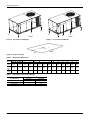
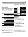
Figure 2: Unit 4 Point Load Weight
Figure 3: Unit 6 Point Load Weight
Y
X
FRONT
LEFT
Figure 4: Center of Gravity
Table 2:
Weights and Dimensions
Weight (lbs.)
Center of Gravity
Size
(Tons) Shipping Operating
X
Y
036
580
575
39
20
(3.0)
048
590
585
39
20
(4.0)
060
595
590
39
20
(5.0)
Table 3:
4 Point Load Location (lbs.)
A
B
C
D
A
6 Point Load Location (lbs.)
B
C
D
E
135
121
151
168
91
85
80
99
106
114
137
124
154
171
93
87
81
101
108
116
138
125
155
172
94
87
82
102
109
117
F
XP036-060 Unit Accessory Weights
Unit Accessory
Economizer
Power Exhaust
Electric Heat1
Weight (lbs.)
Shipping
Operating
55
50
55
50
28
28
1. Weight given is for the maximum heater size available (30KW).
8
Johnson Controls Unitary Products
444463-YIM-D-0311
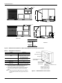
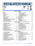
Figure 5: XP036-060 Heat Pump/Electric Heat Front View Physical Dimensions
Johnson Controls Unitary Products
9
444463-YIM-D-0311
27-1/2
1-5/8
27-1/2
19-3/4
19-1/2
44-7/8
Detail “A”
27-1/2
7-1/4
27-1/2
10-1/4
19-1/8
3-1/2
8-1/4
“A”
44-7/8
LH End View
Rear View
Dimension “A”
Fixed
Outdoor
12
Air Damper
Motorized
Damper
4-3/8
Detail “B”
16-1/2
Figure 6: XP036-060 Fixed Outdoor Air Motorized Damper Rain Hood Physical Dimensions
Table 4:
XP036-060 Unit Clearances
Location
Front
Rear
Left Side (Filter Access)
Right Side (Cond. Coil)
Below Unit1
Above Unit2
Clearance
24” (Cooling/Electric Heat)
12” (Less Economizer)
36” (With Economizer or Fixed
Air/Motorized Damper)
24” (Less Economizer)
36” (With Economizer)
24”
0”
72” (For
Condenser Air Discharge)
1. Units may be installed on combustible floors made from
wood or class A, B, or C roof covering material.
2. Units must be installed outdoors. Overhanging structures
or shrubs should not obstruct condenser air discharge
outlet.
NOTE: Units and ductwork are approved for zero clearance
to combustible materials when equipped with electric
heaters.
10
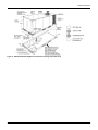
Filter Access
Blower Motor Access
Dot Plugs
Field-Supplied Disconnect
Switch Location
Mounting Bracket for
Disconnect Switch
A,B
(Field Supplied)
Wiring Entry
(See Detail “B”)
Control Box Access
Disconnect Switch Location
and Motor Access Panel for
Unit with “Belt-Drive” Option
Figure 7: XP036-060 Disconnect Location
Johnson Controls Unitary Products
444463-YIM-D-0311
Figure 8: XP036-060 Unit Side Duct Openings
Table 5:
Hole
XP036-060 Utilities Entry
Opening Size (Dia.)
1
A
7/8” KO
B
2” KO1
Used For
Control Wiring
Power Wiring
Side
Bottom2
Side
Bottom
1. Opening in the bottom to the unit can be located by the slice in the
insulation.
2. Do not remove the 2” knockout ring.
Figure 9: XP036-060 Roof Curb
Johnson Controls Unitary Products
11
444463-YIM-D-0311
Ductwork
Compressors
Ductwork should be designed and sized according to the
methods in Manual D of the Air Conditioning Contractors of
America (ACCA) or as recommended by any other recognized
authority such as ASHRAE or SMACNA.
The scroll compressor used in this product is specifically
designed to operate with R-410A Refrigerant and cannot be
interchanged.
A closed return duct system should be used. This will not
preclude use of economizers or outdoor fresh air intake. The
supply and return air duct connections at the unit should be
made with flexible joints to minimize noise.
The supply and return air duct systems should be designed for
the CFM and static pressure requirements of the job. They
should NOT be sized to match the dimensions of the duct
connections on the unit.
Refer to Figure 5 for bottom air duct openings. Refer to Figure 8
for side air duct openings.
When fastening ductwork to side duct flanges on unit,
insert screws through duct flanges only. DO NOT insert
screws through casing. Outdoor ductwork must be
insulated and water-proofed.
Condensate Drain
Plumbing must conform to local codes. Use a sealing compound
on male pipe threads. Install a condensate drain line from the
3/4” PVC female connection on the unit to an open drain.
This system uses R-410A Refrigerant which operates at
higher pressures than R-22. No other refrigerant may be
used in this system.
The compressor also uses a polyolester (POE oil), Mobil 3MA
POE. This oil is extremely hygroscopic, meaning it absorbs
water readily. POE oil can absorb 15 times as much water as
other oils designed for HCFC and CFC refrigerants. Take all
necessary precautions to avoid exposure of the oil to the
atmosphere.
Do not leave the system open to the atmosphere. Unit
damage could occur due to moisture being absorbed by
the POE oil in the system. This type of oil is highly
susceptible to moisture absorption
POE (polyolester) compressor lubricants are known to cause
long term damage to some synthetic roofing materials.
NOTE: The condensate drain operates in a negative pressure
in the cabinet. The condensate drain line MUST be
trapped to provide proper drainage. See Figure 10.
Exposure, even if immediately cleaned up, may cause
embrittlement (leading to cracking) to occur in one year
or more. When performing any service that may risk
exposure of compressor oil to the roof, take precautions
to protect roofing.
Procedures which risk oil leakage include, but are not limited to,
compressor replacement, repairing refrigerant leaks, replacing
refrigerant components such as filter drier, pressure switch,
metering device or coil.
Figure 10: Condensate Drain
Units are shipped with compressor mountings which are
factory-adjusted and ready for operation.
Units with scroll compressors have a shipping bracket which
must be removed after the unit is set in place. See Figure 11.
12
Johnson Controls Unitary Products
444463-YIM-D-0311
Compressor
Mounting bracket
base
208/230-3-60 and 380/415-3-50 units control
transformers are factory wired for 230v and 415v power
supply respectively. Change tap on transformer for 2083-60 or 380-3-50 operation. See unit wiring diagram.
Remove these
screws (2)
Mounting bracket
top (remove)
Wire tie
(cut and remove)
Figure 11: Compressor Restraining Bracket
The internal wiring harnesses furnished with this unit are an
integral part of the design certified unit. Field alteration to
comply with electrical codes should not be required. If any of
the wire supplied with the unit must be replaced, replacement
wire must be of the type shown on the wiring diagram and the
same minimum gauge as the replaced wire.
A disconnect must be utilized for these units. Factory installed
disconnects are available. If installing a disconnect (field
supplied or York International® supplied accessory), refer to
Figure 7 for the recommended mounting location.
Do not loosen compressor mounting bolts.
Filters
One or two-inch filters can be supplied with each unit. One-inch
filters may be used with no modification to the filter racks. Filters
must always be installed ahead of evaporator coil and must be
kept clean or replaced with same size and type. Dirty filters
reduce the capacity of the unit and result in frosted coils or
safety shutdown. Refer to physical data tables, for the number
and size of filters needed for the unit. The unit should not be
operated without filters properly installed.
Make sure that panel latches are properly positioned on
the unit to maintain an airtight seal.
Avoid damage to internal components if drilling holes for
disconnect mounting.
NOTE: Since not all local codes allow the mounting of a
disconnect on the unit, please confirm compliance with
local code before mounting a disconnect on the unit.
Electrical line must be sized properly to carry the load. USE
COPPER CONDUCTORS ONLY. Each unit must be wired with
a separate branch circuit fed directly from the meter panel and
properly fused.
Refer to Figure 12 for typical field wiring and to the appropriate
unit wiring diagram mounted inside control doors for control
circuit and power wiring information.
Power And Control Wiring
Field wiring to the unit, fuses, and disconnects must conform to
provisions of National Electrical Code (NEC), ANSI/NFPA No.
70 – Latest Edition (in U.S.A.), current Canadian Electrical
Code C221, and/or local ordinances. The unit must be
electrically grounded in accordance with NEC and CEC as
specified above and/or local codes.
When connecting electrical power and control wiring to
the unit, water-proof connectors must be used so that
water or moisture cannot be drawn into the unit during
normal operation. The above water-proofing conditions
will also apply when installing a field supplied disconnect
switch.
Voltage tolerances which must be maintained at the
compressor terminals during starting and running conditions are
indicated on the unit Rating Plate and Table 1.
Johnson Controls Unitary Products
13
444463-YIM-D-0311
Power Wiring Detail
subject to drafts, sun exposure or heat from electrical fixtures or
appliances. Follow the manufacturer's instructions enclosed
with thermostat for general installation procedure. Seven (7)
color-coded, insulated wires should be used to connect the
thermostat to the unit. Refer to Table 6 for control wire sizing
and maximum length.
Units are factory wired for the voltage shown on the unit
nameplate. Refer to Electrical Data Table 7 to size power
wiring, fuses, and disconnect switch.
Power wiring is brought into the unit through the side of the unit
or the basepan inside the curb.
Table 6:
Thermostat Wiring
The thermostat should be located on an inside wall
approximately 56 inch above the floor where it will not be
Control Wire Sizes
Wire Size
Maximum Length1
18 AWG
150 Feet
1. From the unit to the thermostat and back to the unit.
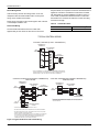
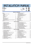
TYPICAL CONTROL WIRING
COOLING / HEATING (24 VOLT THERMOSTAT)
THERMOSTAT 1
TERMINALS
ADD
JUMPER
RH
UNIT TERMINAL
STRIP TB1
RC
R
Y
Y1
24 VOLT
TRANSFORMER
Y2
W
W1
W2
G
G
C
1
24 VOLT THERMOSTAT. TO CONTROL THE ECONOMIZER ON THE SECOND
STAGE COOLING OR TO HAVE AN ELECTRIC HEAT ACCESSORY WITH TWO
STAGES OF HEAT, USE A 2 STAGE COOL AND HEAT THERMOSTAT.
COOLING / HEATING (ELECTRONIC THERMOSTAT)
MULTI STAGE
THERMOSTAT1
TERMINALS
ADD
JUMPER
RC
UNIT TERMINAL
STRIP TB1
RH
R
Y1
W1
4
G
B
C
LED 1
X
NOT
USED
OCC
4
A1
UNIT TERMINAL
STRIP TB1
RC
R
Y
Y1
W
W1
G
G
C
24 VOLT
TRANSFORMER
1 ELECTRONIC
PROGRAMMABLE THERMOSTAT TYPICAL. TO CONTROL THE
ECONOMIZER ON SECOND STAGE COOLING, USE A 2 STAGE COOL AND
HEAT THERMOSTAT.
A2
T
T
TO REMOTE SENSOR
IF USED
1
ELECTRONIC PROGRAMMABLE THERMOSTAT TYPICAL.
2
SECOND STAGE COOLING IS NOT REQUIRED ON UNITS LESS ECONOMIZER.
3
SECOND STAGE HEATING IS ONLY REQUIRED ON UNITS WITH A TWO STAGE
ELECTRIC HEATER OR 2 STAGE GAS HEAT.
4
ADD
JUMPER
W2
G
COM
ADD
JUMPER
Y2
RH
W1
3
W2
LED 2
THERMOSTAT1
TERMINALS
24 VOLT
TRANSFORMER
Y1
2
Y2
COOLING / HEATING (ELECTRONIC THERMOSTAT)
SINGLE STAGE
REMOVE JUMPER J2 FROM TERMINALS 4 AND 9 ON JUMPER PLUG CONNECTOR
P6 ON UNITS WITH ECONOMIZER. TERMINALS A1 AND A2 PROVIDE A RELAY
OUT-PUT TO CLOSE THE OUTDOOR ECONOMIZER DAMPERS WHEN THE
THERMOSTAT SWITCHES TO THE SET-BACK POSITION.
Figure 12: Typical Field Power and Control Wiring
14
Johnson Controls Unitary Products
444463-YIM-D-0311
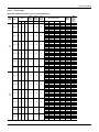
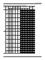
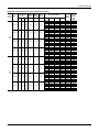
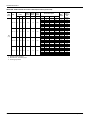
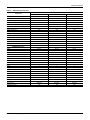
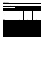
Table 7:
Electrical Data
XP036-060 - Without Powered Convenience Outlet (Belt Drive)
Size
(Tons)
Volt
Compressors
(each)
RLA LRA
MCC
OD Fan
Motors
(each)
Supply
Blower
Motor
Pwr
Conv
Outlet
FLA
FLA
FLA
208-1-60 16.6
88.0
26.0
1.6
7.6
0.0
230-1-60 16.6
88.0
26.0
1.6
7.6
0.0
208-3-60 12.8
95.0
20.0
1.6
5.2
0.0
230-3-60 12.8
95.0
20.0
1.6
5.2
0.0
460-3-60 6.4
45.0
10.0
0.8
2.6
0.0
575-3-60 5.4
38.0
8.5
0.6
2.0
0.0
208-1-60 21.1 113.0 33.0
2.3
7.6
0.0
230-1-60 21.1 113.0 33.0
2.3
7.6
0.0
208-3-60 16.0 120.0 25.0
2.3
5.2
0.0
230-3-60 16.0 120.0 25.0
2.3
5.2
0.0
460-3-60 8.3
60.0
13.0
1.3
2.6
0.0
575-3-60 6.7
40.0
10.5
1.3
2.0
0.0
036
(3.0)
048
(4.0)
Johnson Controls Unitary Products
Electric Heat Option
MCA1
(Amps)
Model
kW
Stages
Amps
None
E05
E07
E10
E15
E20
None
E05
E07
E10
E15
E20
None
E05
E07
E10
E15
E20
None
E05
E07
E10
E15
E20
None
E07
E10
E15
E20
None
E10
E15
E20
None
E05
E07
E10
E15
E20
None
E05
E07
E10
E15
E20
None
E05
E07
E10
E15
E20
None
E05
E07
E10
E15
E20
None
E07
E10
E15
E20
None
E10
E15
E20
4.0
5.6
8.0
11.9
15.9
5.3
7.5
10.6
15.9
21.2
4.0
5.6
8.0
11.9
15.9
5.3
7.5
10.6
15.9
21.2
6.8
10.1
13.6
19.5
10.6
15.9
21.2
4.0
5.6
8.0
11.9
15.9
5.3
7.5
10.6
15.9
21.2
4.0
5.6
8.0
11.9
15.9
5.3
7.5
10.6
15.9
21.2
6.8
10.1
13.6
19.5
10.6
15.9
21.2
1
1
1
2
2
1
1
1
2
2
1
1
1
2
2
1
1
1
2
2
1
1
2
2
1
1
2
1
1
1
2
2
1
1
1
2
2
1
1
1
2
2
1
1
1
2
2
1
1
2
2
1
1
2
19.2
26.9
38.5
57.2
76.4
22.1
31.3
44.2
66.3
88.3
11.1
15.5
22.2
33.0
44.1
12.7
18.0
25.5
38.2
51.0
8.2
12.1
16.4
23.5
10.2
15.3
20.4
19.2
26.9
38.5
57.2
76.4
22.1
31.3
44.2
66.3
88.3
11.1
15.5
22.2
33.0
44.1
12.7
18.0
25.5
38.2
51.0
8.2
12.1
16.4
23.5
10.2
15.3
20.4
30.0
54.0
63.6
78.0
101.5
125.5
30.0
57.6
69.0
85.2
112.8
140.4
22.8
36.7
42.2
50.6
64.1
78.0
22.8
38.7
45.4
54.7
70.6
86.5
11.4
21.6
26.6
31.8
40.7
9.2
22.0
28.4
34.7
36.3
60.3
69.9
84.4
107.8
131.8
36.3
63.9
75.3
91.5
119.1
146.7
27.5
41.4
46.9
55.3
68.8
82.7
27.5
43.4
50.1
59.4
75.3
91.2
14.3
24.5
29.5
34.7
43.6
11.4
24.2
30.5
36.9
Max
Fuse2/
Breaker3
Size
(Amps)
40
60
70
80
110
150
40
60
70
90
125
150
30
45
50
60
70
80
30
45
50
60
80
90
15
25
30
35
45
15
25
30
35
45
70
80
90
110
150
45
70
80
100
125
150
35
50
50
60
70
90
35
50
60
60
80
100
20
30
30
35
45
15
25
35
40
15
444463-YIM-D-0311
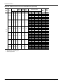
XP036-060 - Without Powered Convenience Outlet (Belt Drive) (Continued)
Size
(Tons)
Volt
Compressors
(each)
RLA LRA
MCC
OD Fan
Motors
(each)
Supply
Blower
Motor
Pwr
Conv
Outlet
FLA
FLA
FLA
208-1-60 26.2 134.0 41.0
2.3
7.6
0.0
230-1-60 26.2 134.0 41.0
2.3
7.6
0.0
208-3-60 15.6 110.0 24.4
2.3
5.2
0.0
230-3-60 15.6 110.0 24.4
2.3
5.2
0.0
460-3-60 7.7
52.0
12.1
1.3
2.6
0.0
575-3-60 5.8
38.9
9.1
1.3
2.0
0.0
060
(5.0)
Electric Heat Option
MCA1
(Amps)
Model
kW
Stages
Amps
None
E05
E07
E10
E15
E20
E30
None
E05
E07
E10
E15
E20
E30
None
E05
E07
E10
E15
E20
E30
None
E05
E07
E10
E15
E20
E30
None
E07
E10
E15
E20
E30
None
E10
E15
E20
E30
4.0
5.6
8.0
11.9
15.9
22.2
5.3
7.5
10.6
15.9
21.2
29.6
4.0
5.6
8.0
11.9
15.9
22.2
5.3
7.5
10.6
15.9
21.2
29.6
6.8
10.1
13.6
19.5
28.8
10.6
15.9
21.2
30.4
1
1
1
2
2
2
1
1
1
2
2
2
1
1
1
2
2
2
1
1
1
2
2
2
1
1
2
2
2
1
1
2
2
19.2
26.9
38.5
57.2
76.4
106.7
22.1
31.3
44.2
66.3
88.3
123.3
11.1
15.5
22.2
33.0
44.1
61.6
12.7
18.0
25.5
38.2
51.0
71.2
8.2
12.1
16.4
23.5
34.6
10.2
15.3
20.4
29.3
42.7
66.7
76.3
90.7
114.2
138.2
176.1
42.7
70.3
81.7
97.9
125.5
153.1
196.8
27.0
40.9
46.4
54.8
68.3
82.2
104.0
27.0
42.9
49.6
58.9
74.8
90.7
116.0
13.5
23.7
28.7
34.0
42.8
56.8
10.3
23.0
29.4
35.8
46.9
Max
Fuse2/
Breaker3
Size
(Amps)
60
80
90
100
125
150
200
60
90
100
110
150
175
200
35
50
50
60
70
90
110
35
50
60
60
80
100
125
20
25
30
35
45
60
15
25
30
40
50
1. Minimum Circuit Ampacity.
2. Dual Element, Time Delay Type.
3. HACR type per NEC.
16
Johnson Controls Unitary Products
444463-YIM-D-0311
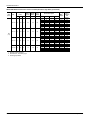
XP036-060 Without Powered Convenience Outlet (Belt Drive High Static)
Size
(Tons)
Volt
Compressors
(each)
RLA LRA
MCC
OD Fan
Motors
(each)
Supply
Blower
Motor
Pwr
Conv
Outlet
FLA
FLA
FLA
208-1-60 16.6
88.0
26.0
1.6
7.6
0.0
230-1-60 16.6
88.0
26.0
1.6
7.6
0.0
208-3-60 12.8
95.0
20.0
1.6
5.2
0.0
230-3-60 12.8
95.0
20.0
1.6
5.2
0.0
460-3-60 6.4
45.0
10.0
0.8
2.6
0.0
575-3-60 5.4
38.0
8.5
0.6
2.0
0.0
208-1-60 21.1 113.0 33.0
2.3
7.6
0.0
230-1-60 21.1 113.0 33.0
2.3
7.6
0.0
208-3-60 16.0 120.0 25.0
2.3
5.2
0.0
230-3-60 16.0 120.0 25.0
2.3
5.2
0.0
460-3-60 8.3
60.0
13.0
1.3
2.6
0.0
575-3-60 6.7
40.0
10.5
1.3
2.0
0.0
036
(3.0)
048
(4.0)
Johnson Controls Unitary Products
Electric Heat Option
MCA1
(Amps)
Model
kW
Stages
Amps
None
E05
E07
E10
E15
E20
None
E05
E07
E10
E15
E20
None
E05
E07
E10
E15
E20
None
E05
E07
E10
E15
E20
None
E07
E10
E15
E20
None
E10
E15
E20
None
E05
E07
E10
E15
E20
None
E05
E07
E10
E15
E20
None
E05
E07
E10
E15
E20
None
E05
E07
E10
E15
E20
None
E07
E10
E15
E20
None
E10
E15
E20
4.0
5.6
8.0
11.9
15.9
5.3
7.5
10.6
15.9
21.2
4.0
5.6
8.0
11.9
15.9
5.3
7.5
10.6
15.9
21.2
6.8
10.1
13.6
19.5
10.6
15.9
21.2
4.0
5.6
8.0
11.9
15.9
5.3
7.5
10.6
15.9
21.2
4.0
5.6
8.0
11.9
15.9
5.3
7.5
10.6
15.9
21.2
6.8
10.1
13.6
19.5
10.6
15.9
21.2
1
1
1
2
2
1
1
1
2
2
1
1
1
2
2
1
1
1
2
2
1
1
2
2
1
1
2
1
1
1
2
2
1
1
1
2
2
1
1
1
2
2
1
1
1
2
2
1
1
2
2
1
1
2
19.2
26.9
38.5
57.2
76.4
22.1
31.3
44.2
66.3
88.3
11.1
15.5
22.2
33.0
44.1
12.7
18.0
25.5
38.2
51.0
8.2
12.1
16.4
23.5
10.2
15.3
20.4
19.2
26.9
38.5
57.2
76.4
22.1
31.3
44.2
66.3
88.3
11.1
15.5
22.2
33.0
44.1
12.7
18.0
25.5
38.2
51.0
8.2
12.1
16.4
23.5
10.2
15.3
20.4
30.0
54.0
63.6
78.0
101.5
125.5
30.0
57.6
69.0
85.2
112.8
140.4
22.8
36.7
42.2
50.6
64.1
78.0
22.8
38.7
45.4
54.7
70.6
86.5
11.4
21.6
26.6
31.8
40.7
9.2
22.0
28.4
34.7
36.3
60.3
69.9
84.4
107.8
131.8
36.3
63.9
75.3
91.5
119.1
146.7
27.5
41.4
46.9
55.3
68.8
82.7
27.5
43.4
50.1
59.4
75.3
91.2
14.3
24.5
29.5
34.7
43.6
11.4
24.2
30.5
36.9
Max
Fuse2/
Breaker3
Size
(Amps)
40
60
70
80
110
150
40
60
70
90
125
150
30
45
50
60
70
80
30
45
50
60
80
90
15
25
30
35
45
15
25
30
35
45
70
80
90
110
150
45
70
80
100
125
150
35
50
50
60
70
90
35
50
60
60
80
100
20
30
30
35
45
15
25
35
40
17
444463-YIM-D-0311
XP036-060 Without Powered Convenience Outlet (Belt Drive High Static) (Continued)
Size
(Tons)
Volt
Compressors
(each)
RLA LRA
MCC
OD Fan
Motors
(each)
Supply
Blower
Motor
Pwr
Conv
Outlet
FLA
FLA
FLA
208-3-60 15.6 110.0 24.4
2.3
8.2
0.0
230-3-60 15.6 110.0 24.4
2.3
8.2
0.0
460-3-60 7.7
52.0
12.1
1.3
4.1
0.0
575-3-60 5.8
38.9
9.1
1.3
3.6
0.0
060
(5.0)
Electric Heat Option
MCA1
(Amps)
Model
kW
Stages
Amps
None
E05
E07
E10
E15
E20
E30
None
E05
E07
E10
E15
E20
E30
None
E07
E10
E15
E20
E30
None
E10
E15
E20
E30
4.0
5.6
8.0
11.9
15.9
22.2
5.3
7.5
10.6
15.9
21.2
29.6
6.8
10.1
13.6
19.5
28.8
10.6
15.9
21.2
30.4
1
1
1
2
2
2
1
1
1
2
2
2
1
1
2
2
2
1
1
2
2
11.1
15.5
22.2
33.0
44.1
61.6
12.7
18.0
25.5
38.2
51.0
71.2
8.2
12.1
16.4
23.5
34.6
10.2
15.3
20.4
29.3
30.0
43.9
49.4
57.8
71.3
85.2
107.0
30.0
45.9
52.6
61.9
77.8
93.7
119.0
15.0
25.2
30.2
35.5
44.3
58.3
11.9
24.6
31.0
37.4
48.5
Max
Fuse2/
Breaker3
Size
(Amps)
40
50
60
60
80
90
110
40
50
60
70
80
100
125
20
30
35
40
45
60
15
25
35
40
50
1. Minimum Circuit Ampacity.
2. Dual Element, Time Delay Type.
3. HACR type per NEC.
18
Johnson Controls Unitary Products
444463-YIM-D-0311
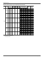
XP036-060 - Without Powered Convenience Outlet (Direct Drive)
Size
(Tons)
Volt
Compressors
(each)
RLA LRA
MCC
OD Fan
Motors
(each)
Supply
Blower
Motor
Pwr
Conv
Outlet
FLA
FLA
FLA
208-1-60 16.6
88.0
26.0
1.6
6.0
0.0
230-1-60 16.6
88.0
26.0
1.6
6.0
0.0
208-3-60 12.8
95.0
20.0
1.6
6.0
0.0
230-3-60 12.8
95.0
20.0
1.6
6.0
0.0
208-1-60 21.1 113.0 33.0
2.3
7.6
0.0
230-1-60 21.1 113.0 33.0
2.3
7.6
0.0
208-3-60 16.0 120.0 25.0
2.3
7.6
0.0
230-3-60 16.0 120.0 25.0
2.3
7.6
0.0
036
(3.0)
048
(4.0)
Johnson Controls Unitary Products
Electric Heat Option
MCA1
(Amps)
Model
kW
Stages
Amps
None
E05
E07
E10
E15
E20
None
E05
E07
E10
E15
E20
None
E05
E07
E10
E15
E20
None
E05
E07
E10
E15
E20
None
E05
E07
E10
E15
E20
None
E05
E07
E10
E15
E20
None
E05
E07
E10
E15
E20
None
E05
E07
E10
E15
E20
4.0
5.6
8.0
11.9
15.9
5.3
7.5
10.6
15.9
21.2
4.0
5.6
8.0
11.9
15.9
5.3
7.5
10.6
15.9
21.2
4.0
5.6
8.0
11.9
15.9
5.3
7.5
10.6
15.9
21.2
4.0
5.6
8.0
11.9
15.9
5.3
7.5
10.6
15.9
21.2
1
1
1
2
2
1
1
1
2
2
1
1
1
2
2
1
1
1
2
2
1
1
1
2
2
1
1
1
2
2
1
1
1
2
2
1
1
1
2
2
19.2
26.9
38.5
57.2
76.4
22.1
31.3
44.2
66.3
88.3
11.1
15.5
22.2
33.0
44.1
12.7
18.0
25.5
38.2
51.0
19.2
26.9
38.5
57.2
76.4
22.1
31.3
44.2
66.3
88.3
11.1
15.5
22.2
33.0
44.1
12.7
18.0
25.5
38.2
51.0
28.4
52.4
62.0
76.4
99.9
123.9
28.4
56.0
67.4
83.6
111.2
138.8
23.6
37.5
43.0
51.4
64.9
78.8
23.6
39.5
46.2
55.5
71.4
87.3
36.3
60.3
69.9
84.4
107.8
131.8
36.3
63.9
75.3
91.5
119.1
146.7
29.9
43.8
49.3
57.7
71.2
85.1
29.9
45.8
52.5
61.8
77.7
93.6
Max
Fuse2/
Breaker3
Size
(Amps)
35
60
70
80
100
125
35
60
70
90
125
150
30
45
50
60
70
80
30
45
50
60
80
90
45
70
80
90
110
150
45
70
80
100
125
150
40
50
60
60
80
90
40
50
60
70
80
100
19
444463-YIM-D-0311
XP036-060 - Without Powered Convenience Outlet (Direct Drive) (Continued)
Size
(Tons)
Volt
Compressors
(each)
RLA LRA
MCC
OD Fan
Motors
(each)
Supply
Blower
Motor
Pwr
Conv
Outlet
FLA
FLA
FLA
208-1-60 26.2 134.0 41.0
2.3
7.6
0.0
230-1-60 26.2 134.0 41.0
2.3
7.6
0.0
208-3-60 15.6 110.0 24.4
2.3
7.6
0.0
230-3-60 15.6 110.0 24.4
2.3
7.6
0.0
060
(5.0)
Electric Heat Option
MCA1
(Amps)
Model
kW
Stages
Amps
None
E05
E07
E10
E15
E20
E30
None
E05
E07
E10
E15
E20
E30
None
E05
E07
E10
E15
E20
E30
None
E05
E07
E10
E15
E20
E30
4.0
5.6
8.0
11.9
15.9
22.2
5.3
7.5
10.6
15.9
21.2
29.6
4.0
5.6
8.0
11.9
15.9
22.2
5.3
7.5
10.6
15.9
21.2
29.6
1
1
1
2
2
2
1
1
1
2
2
2
1
1
1
2
2
2
1
1
1
2
2
2
19.2
26.9
38.5
57.2
76.4
106.7
22.1
31.3
44.2
66.3
88.3
123.3
11.1
15.5
22.2
33.0
44.1
61.6
12.7
18.0
25.5
38.2
51.0
71.2
42.7
66.7
76.3
90.7
114.2
138.2
176.1
42.7
70.3
81.7
97.9
125.5
153.1
196.8
29.4
43.3
48.8
57.2
70.7
84.6
106.4
29.4
45.3
52.0
61.3
77.2
93.1
118.4
Max
Fuse2/
Breaker3
Size
(Amps)
60
80
90
100
125
150
200
60
90
100
110
150
175
200
40
50
60
60
80
90
110
40
50
60
70
80
100
125
1. Minimum Circuit Ampacity.
2. Dual Element, Time Delay Type.
3. HACR type per NEC.
20
Johnson Controls Unitary Products
444463-YIM-D-0311
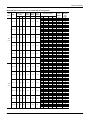
XP036-060 - With Powered Convenience Outlet (Belt Drive)
Size
(Tons)
Volt
Compressors
(each)
RLA LRA
MCC
OD Fan
Motors
(each)
FLA
Supply
Blower
Motor
FLA
Pwr
Conv
Outlet
FLA
208-1-60 16.6
88.0
26.0
1.6
7.6
10.0
230-1-60 16.6
88.0
26.0
1.6
7.6
10.0
208-3-60 12.8
95.0
20.0
1.6
5.2
10.0
230-3-60 12.8
95.0
20.0
1.6
5.2
10.0
460-3-60 6.4
45.0
10.0
0.8
2.6
5.0
575-3-60 5.4
38.0
8.5
0.6
2.0
4.0
208-1-60 21.1 113.0 33.0
2.3
7.6
10.0
230-1-60 21.1 113.0 33.0
2.3
7.6
10.0
208-3-60 16.0 120.0 25.0
2.3
5.2
10.0
230-3-60 16.0 120.0 25.0
2.3
5.2
10.0
460-3-60 8.3
60.0
13.0
1.3
2.6
5.0
575-3-60 6.7
40.0
10.5
1.3
2.0
4.0
036
(3.0)
048
(4.0)
Johnson Controls Unitary Products
Electric Heat Option
Model
None
E05
E07
E10
E15
E20
None
E05
E07
E10
E15
E20
None
E05
E07
E10
E15
E20
None
E05
E07
E10
E15
E20
None
E07
E10
E15
E20
None
E10
E15
E20
None
E05
E07
E10
E15
E20
None
E05
E07
E10
E15
E20
None
E05
E07
E10
E15
E20
None
E05
E07
E10
E15
E20
None
E07
E10
E15
E20
None
E10
E15
E20
kW
4.0
5.6
8.0
11.9
15.9
5.3
7.5
10.6
15.9
21.2
4.0
5.6
8.0
11.9
15.9
5.3
7.5
10.6
15.9
21.2
6.8
10.1
13.6
19.5
10.6
15.9
21.2
4.0
5.6
8.0
11.9
15.9
5.3
7.5
10.6
15.9
21.2
4.0
5.6
8.0
11.9
15.9
5.3
7.5
10.6
15.9
21.2
6.8
10.1
13.6
19.5
10.6
15.9
21.2
Stages
1
1
1
2
2
1
1
1
2
2
1
1
1
2
2
1
1
1
2
2
1
1
2
2
1
1
2
1
1
1
2
2
1
1
1
2
2
1
1
1
2
2
1
1
1
2
2
1
1
2
2
1
1
2
Amps
19.2
26.9
38.5
57.2
76.4
22.1
31.3
44.2
66.3
88.3
11.1
15.5
22.2
33.0
44.1
12.7
18.0
25.5
38.2
51.0
8.2
12.1
16.4
23.5
10.2
15.3
20.4
19.2
26.9
38.5
57.2
76.4
22.1
31.3
44.2
66.3
88.3
11.1
15.5
22.2
33.0
44.1
12.7
18.0
25.5
38.2
51.0
8.2
12.1
16.4
23.5
10.2
15.3
20.4
MCA1
(Amps)
40.0
64.0
73.6
88.0
111.5
135.5
40.0
67.6
79.0
95.2
122.8
150.4
32.8
46.7
52.2
60.6
74.1
88.0
32.8
48.7
55.4
64.7
80.6
96.5
16.4
26.6
31.6
36.8
45.7
13.2
26.0
32.4
38.7
46.3
70.3
79.9
94.4
117.8
141.8
46.3
73.9
85.3
101.5
129.1
156.7
37.5
51.4
56.9
65.3
78.8
92.7
37.5
53.4
60.1
69.4
85.3
101.2
19.3
29.5
34.5
39.7
48.6
15.4
28.2
34.5
40.9
Max Fuse2/
Breaker3
Size
(Amps)
50
70
80
90
125
150
50
70
80
100
125
175
40
50
60
70
80
90
40
50
60
70
90
100
20
30
35
40
50
15
30
35
40
60
80
90
100
125
150
60
80
90
110
150
175
50
60
60
70
80
100
50
60
70
70
90
110
25
35
35
40
50
20
30
35
45
21
444463-YIM-D-0311
XP036-060 - With Powered Convenience Outlet (Belt Drive) (Continued)
Size
(Tons)
Volt
Compressors
(each)
RLA LRA
MCC
OD Fan
Motors
(each)
FLA
Supply
Blower
Motor
FLA
Pwr
Conv
Outlet
FLA
208-1-60 26.2 134.0 41.0
2.3
7.6
10.0
230-1-60 26.2 134.0 41.0
2.3
7.6
10.0
208-3-60 15.6 110.0 24.4
2.3
5.2
10.0
230-3-60 15.6 110.0 24.4
2.3
5.2
10.0
460-3-60 7.7
52.0
12.1
1.3
2.6
5.0
575-3-60 5.8
38.9
9.1
1.3
2.0
4.0
060
(5.0)
Electric Heat Option
Model
None
E05
E07
E10
E15
E20
E30
None
E05
E07
E10
E15
E20
E30
None
E05
E07
E10
E15
E20
E30
None
E05
E07
E10
E15
E20
E30
None
E07
E10
E15
E20
E30
None
E10
E15
E20
E30
kW
4.0
5.6
8.0
11.9
15.9
22.2
5.3
7.5
10.6
15.9
21.2
29.6
4.0
5.6
8.0
11.9
15.9
22.2
5.3
7.5
10.6
15.9
21.2
29.6
6.8
10.1
13.6
19.5
28.8
10.6
15.9
21.2
30.4
Stages
1
1
1
2
2
2
1
1
1
2
2
2
1
1
1
2
2
2
1
1
1
2
2
2
1
1
2
2
2
1
1
2
2
Amps
19.2
26.9
38.5
57.2
76.4
106.7
22.1
31.3
44.2
66.3
88.3
123.3
11.1
15.5
22.2
33.0
44.1
61.6
12.7
18.0
25.5
38.2
51.0
71.2
8.2
12.1
16.4
23.5
34.6
10.2
15.3
20.4
29.3
MCA1
(Amps)
52.7
76.7
86.3
100.7
124.2
148.2
186.1
52.7
80.3
91.7
107.9
135.5
163.1
206.8
37.0
50.9
56.4
64.8
78.3
92.2
114.0
37.0
52.9
59.6
68.9
84.8
100.7
126.0
18.5
28.7
33.7
39.0
47.8
61.8
14.3
27.0
33.4
39.8
50.9
Max Fuse2/
Breaker3
Size
(Amps)
70
90
100
110
125
150
200
70
100
110
110
150
175
225
45
60
60
70
80
100
125
45
60
70
70
90
110
150
25
30
35
40
50
70
20
30
35
40
60
1. Minimum Circuit Ampacity.
2. Dual Element, Time Delay Type.
3. HACR type per NEC.
22
Johnson Controls Unitary Products
444463-YIM-D-0311
XP036-060 With Powered Convenience Outlet (Belt Drive High Static)
Size
(Tons)
Volt
Compressors
(each)
RLA LRA
MCC
OD Fan
Motors
(each)
FLA
Supply
Blower
Motor
FLA
Pwr
Conv
Outlet
FLA
208-1-60 16.6
88.0
26.0
1.6
7.6
10.0
230-1-60 16.6
88.0
26.0
1.6
7.6
10.0
208-3-60 12.8
95.0
20.0
1.6
5.2
10.0
230-3-60 12.8
95.0
20.0
1.6
5.2
10.0
460-3-60 6.4
45.0
10.0
0.8
2.6
5.0
575-3-60 5.4
38.0
8.5
0.6
2.0
4.0
208-1-60 21.1 113.0 33.0
2.3
7.6
10.0
230-1-60 21.1 113.0 33.0
2.3
7.6
10.0
208-3-60 16.0 120.0 25.0
2.3
5.2
10.0
230-3-60 16.0 120.0 25.0
2.3
5.2
10.0
460-3-60 8.3
60.0
13.0
1.3
2.6
5.0
575-3-60 6.7
40.0
10.5
1.3
2.0
4.0
036
(3.0)
048
(4.0)
Johnson Controls Unitary Products
Electric Heat Option
Model
None
E05
E07
E10
E15
E20
None
E05
E07
E10
E15
E20
None
E05
E07
E10
E15
E20
None
E05
E07
E10
E15
E20
None
E07
E10
E15
E20
None
E10
E15
E20
None
E05
E07
E10
E15
E20
None
E05
E07
E10
E15
E20
None
E05
E07
E10
E15
E20
None
E05
E07
E10
E15
E20
None
E07
E10
E15
E20
None
E10
E15
E20
kW
4.0
5.6
8.0
11.9
15.9
5.3
7.5
10.6
15.9
21.2
4.0
5.6
8.0
11.9
15.9
5.3
7.5
10.6
15.9
21.2
6.8
10.1
13.6
19.5
10.6
15.9
21.2
4.0
5.6
8.0
11.9
15.9
5.3
7.5
10.6
15.9
21.2
4.0
5.6
8.0
11.9
15.9
5.3
7.5
10.6
15.9
21.2
6.8
10.1
13.6
19.5
10.6
15.9
21.2
Stages
1
1
1
2
2
1
1
1
2
2
1
1
1
2
2
1
1
1
2
2
1
1
2
2
1
1
2
1
1
1
2
2
1
1
1
2
2
1
1
1
2
2
1
1
1
2
2
1
1
2
2
1
1
2
Amps
19.2
26.9
38.5
57.2
76.4
22.1
31.3
44.2
66.3
88.3
11.1
15.5
22.2
33.0
44.1
12.7
18.0
25.5
38.2
51.0
8.2
12.1
16.4
23.5
10.2
15.3
20.4
19.2
26.9
38.5
57.2
76.4
22.1
31.3
44.2
66.3
88.3
11.1
15.5
22.2
33.0
44.1
12.7
18.0
25.5
38.2
51.0
8.2
12.1
16.4
23.5
10.2
15.3
20.4
MCA1
(Amps)
40.0
64.0
73.6
88.0
111.5
135.5
40.0
67.6
79.0
95.2
122.8
150.4
32.8
46.7
52.2
60.6
74.1
88.0
32.8
48.7
55.4
64.7
80.6
96.5
16.4
26.6
31.6
36.8
45.7
13.2
26.0
32.4
38.7
46.3
70.3
79.9
94.4
117.8
141.8
46.3
73.9
85.3
101.5
129.1
156.7
37.5
51.4
56.9
65.3
78.8
92.7
37.5
53.4
60.1
69.4
85.3
101.2
19.3
29.5
34.5
39.7
48.6
15.4
28.2
34.5
40.9
Max Fuse2/
Breaker3
Size
(Amps)
50
70
80
90
125
150
50
70
80
100
125
175
40
50
60
70
80
90
40
50
60
70
90
100
20
30
35
40
50
15
30
35
40
60
80
90
100
125
150
60
80
90
110
150
175
50
60
60
70
80
100
50
60
70
70
90
110
25
35
35
40
50
20
30
35
45
23
444463-YIM-D-0311
XP036-060 With Powered Convenience Outlet (Belt Drive High Static) (Continued)
Size
(Tons)
Volt
Compressors
(each)
RLA LRA
MCC
OD Fan
Motors
(each)
FLA
Supply
Blower
Motor
FLA
Pwr
Conv
Outlet
FLA
208-3-60 15.6 110.0 24.4
2.3
8.2
10.0
230-3-60 15.6 110.0 24.4
2.3
8.2
10.0
460-3-60 7.7
52.0
12.1
1.3
4.1
5.0
575-3-60 5.8
38.9
9.1
1.3
3.6
4.0
060
(5.0)
Electric Heat Option
Model
None
E05
E07
E10
E15
E20
E30
None
E05
E07
E10
E15
E20
E30
None
E07
E10
E15
E20
E30
None
E10
E15
E20
E30
kW
4.0
5.6
8.0
11.9
15.9
22.2
5.3
7.5
10.6
15.9
21.2
29.6
6.8
10.1
13.6
19.5
28.8
10.6
15.9
21.2
30.4
Stages
1
1
1
2
2
2
1
1
1
2
2
2
1
1
2
2
2
1
1
2
2
Amps
11.1
15.5
22.2
33.0
44.1
61.6
12.7
18.0
25.5
38.2
51.0
71.2
8.2
12.1
16.4
23.5
34.6
10.2
15.3
20.4
29.3
MCA1
(Amps)
40.0
53.9
59.4
67.8
81.3
95.2
117.0
40.0
55.9
62.6
71.9
87.8
103.7
129.0
20.0
30.2
35.2
40.5
49.3
63.3
15.9
28.6
35.0
41.4
52.5
Max Fuse2/
Breaker3
Size
(Amps)
50
60
70
70
90
100
125
50
60
70
80
90
110
150
25
35
40
45
50
70
20
30
40
45
60
1. Minimum Circuit Ampacity.
2. Dual Element, Time Delay Type.
3. HACR type per NEC.
24
Johnson Controls Unitary Products
444463-YIM-D-0311
XP036-060 - With Powered Convenience Outlet (Direct Drive)
Size
(Tons)
Volt
Compressors
(each)
RLA LRA
MCC
OD Fan
Motors
(each)
Supply
Blower
Motor
Pwr
Conv
Outlet
FLA
FLA
FLA
208-1-60 16.6
88.0
26.0
1.6
6.0
10.0
230-1-60 16.6
88.0
26.0
1.6
6.0
10.0
208-3-60 12.8
95.0
20.0
1.6
6.0
10.0
230-3-60 12.8
95.0
20.0
1.6
6.0
10.0
208-1-60 21.1 113.0 33.0
2.3
7.6
10.0
230-1-60 21.1 113.0 33.0
2.3
7.6
10.0
208-3-60 16.0 120.0 25.0
2.3
7.6
10.0
230-3-60 16.0 120.0 25.0
2.3
7.6
10.0
036
(3.0)
048
(4.0)
Johnson Controls Unitary Products
Electric Heat Option
MCA1
(Amps)
Model
kW
Stages
Amps
None
E05
E07
E10
E15
E20
None
E05
E07
E10
E15
E20
None
E05
E07
E10
E15
E20
None
E05
E07
E10
E15
E20
None
E05
E07
E10
E15
E20
None
E05
E07
E10
E15
E20
None
E05
E07
E10
E15
E20
None
E05
E07
E10
E15
E20
4.0
5.6
8.0
11.9
15.9
5.3
7.5
10.6
15.9
21.2
4.0
5.6
8.0
11.9
15.9
5.3
7.5
10.6
15.9
21.2
4.0
5.6
8.0
11.9
15.9
5.3
7.5
10.6
15.9
21.2
4.0
5.6
8.0
11.9
15.9
5.3
7.5
10.6
15.9
21.2
1
1
1
2
2
1
1
1
2
2
1
1
1
2
2
1
1
1
2
2
1
1
1
2
2
1
1
1
2
2
1
1
1
2
2
1
1
1
2
2
19.2
26.9
38.5
57.2
76.4
22.1
31.3
44.2
66.3
88.3
11.1
15.5
22.2
33.0
44.1
12.7
18.0
25.5
38.2
51.0
19.2
26.9
38.5
57.2
76.4
22.1
31.3
44.2
66.3
88.3
11.1
15.5
22.2
33.0
44.1
12.7
18.0
25.5
38.2
51.0
38.4
62.4
72.0
86.4
109.9
133.9
38.4
66.0
77.4
93.6
121.2
148.8
33.6
47.5
53.0
61.4
74.9
88.8
33.6
49.5
56.2
65.5
81.4
97.3
46.3
70.3
79.9
94.4
117.8
141.8
46.3
73.9
85.3
101.5
129.1
156.7
39.9
53.8
59.3
67.7
81.2
95.1
39.9
55.8
62.5
71.8
87.7
103.6
Max
Fuse2/
Breaker3
Size
(Amps)
50
70
80
90
110
150
50
70
80
100
125
150
45
50
60
70
80
90
45
50
60
70
90
100
60
80
90
100
125
150
60
80
90
110
150
175
50
60
70
70
90
100
50
60
70
80
90
110
25
444463-YIM-D-0311
XP036-060 - With Powered Convenience Outlet (Direct Drive) (Continued)
Size
(Tons)
Volt
Compressors
(each)
RLA LRA
MCC
OD Fan
Motors
(each)
Supply
Blower
Motor
Pwr
Conv
Outlet
FLA
FLA
FLA
208-1-60 26.2 134.0 41.0
2.3
7.6
10.0
230-1-60 26.2 134.0 41.0
2.3
7.6
10.0
208-3-60 15.6 110.0 24.4
2.3
7.6
10.0
230-3-60 15.6 110.0 24.4
2.3
7.6
10.0
060
(5.0)
Electric Heat Option
MCA1
(Amps)
Model
kW
Stages
Amps
None
E05
E07
E10
E15
E20
E30
None
E05
E07
E10
E15
E20
E30
None
E05
E07
E10
E15
E20
E30
None
E05
E07
E10
E15
E20
E30
4.0
5.6
8.0
11.9
15.9
22.2
5.3
7.5
10.6
15.9
21.2
29.6
4.0
5.6
8.0
11.9
15.9
22.2
5.3
7.5
10.6
15.9
21.2
29.6
1
1
1
2
2
2
1
1
1
2
2
2
1
1
1
2
2
2
1
1
1
2
2
2
19.2
26.9
38.5
57.2
76.4
106.7
22.1
31.3
44.2
66.3
88.3
123.3
11.1
15.5
22.2
33.0
44.1
61.6
12.7
18.0
25.5
38.2
51.0
71.2
52.7
76.7
86.3
100.7
124.2
148.2
186.1
52.7
80.3
91.7
107.9
135.5
163.1
206.8
39.4
53.3
58.8
67.2
80.7
94.6
116.4
39.4
55.3
62.0
71.3
87.2
103.1
128.4
Max
Fuse2/
Breaker3
Size
(Amps)
70
90
100
110
125
150
200
70
100
110
110
150
175
225
50
60
70
70
90
100
125
50
60
70
80
90
110
150
1. Minimum Circuit Ampacity.
2. Dual Element, Time Delay Type.
3. HACR type per NEC.
26
Johnson Controls Unitary Products
444463-YIM-D-0311
Table 8:
XP036-060 Physical Data
Component
Models
XP036
XP048
XP060
3.0
4.0
5.0
Gross Capacity @ ARI A point (Btu)
36200
48500
60100
ARI net capacity (Btu)
35000
46500
57500
EER
11.0
10.8
10.6
SEER
13.0
13.0
13.0
Nominal CFM
1200
1600
1850
Nominal Tonnage
ARI COOLING PERFORMANCE
System power (KW)
Refrigerant type
Refrigerant charge (lb-oz)
3.25
4.26
5.42
R-410A
R-410A
R-410A
13-0
13-0
12-10
ARI HEATING PERFORMANCE
47°F capacity rating (MBH)
34800
45000
56500
System power (KW) / COP
3.29 (kW) / 3.10
4.06 (kW) / 3.25
5.4 (kW) / 3.10
17°F capacity rating (MBH
19000
27000
34400
System power (KW) / COP
2.60 (kW) / 2.15
3.86 (kW) / 2.06
4.75 (kW) / 2.10
7.70
7.70
7.70
HSPF (Btu/Watts-hr)
DIMENSIONS (inches)
Length
82-1/4
82-1/4
82-1/4
Width
44-7/8
44-7/8
44-7/8
32-5/8
32-5/8
32-5/8
575
585
590
Scroll
Scroll
Scroll
1
1
1
16.88
Height
OPERATING WT. (lbs.)
COMPRESSORS
Type
Quantity
CONDENSER COIL DATA
Face area (Sq. Ft.)
16.88
16.88
Rows
2
2
2
Fins per inch
18
18
18
Tube diameter
3/8
3/8
3/8
Circuitry Type
Split-face
Split-face
Split-face
5.06
EVAPORATOR COIL DATA
Face area (Sq. Ft.)
5.06
5.06
Rows
4
4
4
Fins per inch
13
13
13
Tube diameter
0.375
0.375
0.375
Circuitry Type
Split-face
Split-face
Split-face
TXV
TXV
TXV
Refrigerant control
Johnson Controls Unitary Products
27
444463-YIM-D-0311
Table 8:
XP036-060 Physical Data (Continued)
Models
Component
Nominal Tonnage
XP036
XP048
XP060
3.0
4.0
5.0
CONDENSER FAN DATA
Quantity
1
1
1
Fan diameter (Inch)
24
24
24
Type
Prop
Prop
Prop
Drive type
Direct Drive
Direct Drive
Direct Drive
No. speeds
1
1
1
Number of motors
1
1
1
Motor HP each
1/4
1/2
1/2
RPM
850
1090
1090
3275
4200
4200
Nominal total CFM
BELT DRIVE EVAP FAN DATA
Quantity
Fan Size (Inch)
Type
1
1
1
12 x 10
12 x 10
12 x 10
Centrifugal
Centrifugal
Centrifugal
Motor Sheave
1VL44
1VP56
1VL44
1VP56
1VL44
1VP56
Blower Sheave
AK64
AK66
AK56
AK61
AK56
AK56
Belt
A37
A39
A36
A38
A36
A38
Motor HP each
1-1/2
1-1/2
1-1/2
1-1/2
1-1/2
RPM
Frame size
2
1725
1725
1725
56
56
56
DIRECT DRIVE EVAP FAN DATA
Quantity
1
1
1
12 x 10
12 x 10
12 x 10
Centrifugal
Centrifugal
Centrifugal
3/4
1
1
1050
1050
1050
15” x 20” x 1” or 2”
2
2
2
14” x 25” x 1” or 2”
1
1
1
Fan Size (Inch)
Type
Motor HP each
RPM
FILTERS
28
Johnson Controls Unitary Products
444463-YIM-D-0311
Optional Electric Heat
The factory or field installed heaters are wired for single point
power supply. Power supply need only be brought into the
single point terminal block, and thermostat wiring to the low
voltage terminal strip located in the upper portion of the unit
control box.
Table 9:
These CSA approved heaters are located within the central
compartment of the unit with the heater elements extending in
to the supply air chamber.
Fuses are supplied, where required, by the factory. Some kW
sizes require fuses and others do not. refer to Table 9 for
minimum CFM limitations and to Table 7 for electrical data.
Electric Heat Minimum Supply Air
Size
(Tons)
036
(3.0)
048
(4.0)
060
(5.0)
Voltage
208/230-1-60
208/230-3-60
460-3-60
600-3-60
208/230-1-60
208/230-3-60
460-3-60
600-3-60
208/230-1-60
208/230-3-60
460-3-60
600-3-60
5
900
900
1200
1200
1500
1500
-
7
900
900
900
1200
1200
1200
1500
1500
1500
-
Options/Accessories
Economizer/Motorized Damper and Rain Hood
The instruction for the optional economizer/motorized damper
and rain hood can be found in form 035-07364-000. Use these
instructions when field assembling an economizer rain hood
onto a unit. The outdoor and return air dampers, the damper
actuator, the damper linkage, the outdoor and return air divider
baffles, and all the control sensors are factory mounted as part
of the “Factory installed” economizer/motorized damper options.
Power Exhaust/barometric Relief Damper and Rain Hood
The instructions for the power exhaust/barometric relief damper
and rain hood can be found in form 530.18-N1.10V.
Minimum Supply Air (CFM)
Heater kW
10
15
900
900
900
900
900
900
900
900
1200
1200
1200
1200
1200
1200
1200
1200
1500
1500
1500
1500
1500
1500
1500
1500
20
900
900
900
900
1200
1200
1200
1200
1500
1500
1500
1500
30
1500
1500
1500
1500
Minimum Position Adjustment
• Check that the damper blades move smoothly without
binding; carefully turn the Minimum Position Adjust screw
(found on the damper control module) fully clockwise and
then set the thermostat indoor fan switch to the ON
position and then OFF or energize and de-energize
terminals “R” to “G”.
• With the thermostat set to the indoor fan ON position or
terminals “R” to “G” energized, turn the Minimum Position
Adjusting screw (located on the damper control module)
counterclockwise until the desired minimum damper
position has been attained.
Enthalpy Set Point Adjustment
All of the components, including the dampers, hardware, and
mounting instructions are shipped in a single package external
from the unit and must be field assembled and installed.
• The enthalpy set point may now be set by selecting the
desired set point shown in the Enthalpy Set Point
Adjustment Figure 13. Adjust as follows:
Power exhaust is only available as a field installed accessory.
• For a single enthalpy operation carefully turn the set point
adjusting screw (found on the damper control module) to
the “A”, “B”, “C” or “D” setting corresponding to the lettered
curve of the Enthalpy Set Point Adjustment Figure 14.
Economizer And Power Exhaust Set Point
Adjustments
Remove the top rear access panel from the unit. Locate the
economizer control module, where the following adjustments
will be made.
• For a dual enthalpy operation, carefully turn the set point
adjusting screw fully clockwise past the "D" setting.
Extreme care must be exercised in turning all set point,
maximum and minimum damper positioning adjustment
screws to prevent twisting them off.
Johnson Controls Unitary Products
29
444463-YIM-D-0311
Power Exhaust Damper Set Point (With Or Without Power
Exhaust)
• With no power exhaust option, adjust the Exhaust Air
Adjustment Screw fully clockwise.
• With power exhaust option, each building pressurization
requirement will be different. The point at which the power
exhaust comes on is determined by the economizer
damper position (Percent Open). The Exhaust Air
Adjustment Screw should be set at the Percent Open of
the economizer damper at which the power exhaust is
needed. It can be set from 0 to 100% damper open.
CONTROL
CURVE
CONTROL POINT
APPROX. 0F (0C)
AT 50% RH
A
73 (23)
B
C
70 (21)
67 (19)
D
63 (17)
85 90 95 100 105 110
(29) (32) (35) (38) (41) (43)
80
(27)
75
(24)
70
(21)
65
(18)
Indoor Air Quality AQ
Indoor Air Quality (indoor sensor input): Terminal AQ accepts a
+2 to +10 Vdc signal with respect to the (AQ1) terminal. When
the signal is below it's set point, the actuator is allowed to
modulate normally in accordance with the enthalpy and mixed
air sensor inputs. When the AQ signal exceeds it's set point
setting and there is no call for free cooling, the actuator is
proportionately modulated from the 2 to 10 Vdc signal, with 2
Vdc corresponding to full closed and 10 Vdc corresponding to
full open. When there is no call for free cooling, the damper
position is limited by the IAQ Max damper position setting.
When the signal exceeds it's set point (Demand Control
Ventilation Set Point) setting and there is a call for free cooling,
the actuator modulates from the minimum position to the full
open position based on the highest call from either the mixed
air sensor input or the AQ voltage input.
• Optional CO2 Space Sensor Kit Part # 2AQ04700324
• Optional CO2 Sensor Kit Part # 2AQ04700424
Replace the economizer access panel.
60
(16)
55
(13)
50
(10)
45
(7)
35
(2)
A
B
C
D
40
(4)
B A
D C
35
(2)
40 45 50 55 60 65 70 75 80 85 90 95 100 105 110
(4) (7) (10) (13) (16) (18) (21) (24) (27) (29) (32) (35) (38) (41) (43)
APPROXIMATE DRY BULB TEMPERATURE - 0F (0C)
Figure 13: Enthalpy Set Point Chart
Exhaust Air
Adjustment
Screw
Exhaust Air LED
Damper Min.
Position
Screw
Indoor Air Quality
Max. Adjustment
Screw
N1
N
EXH
Set
TR
P1
P
EXH
24
Vac
HOT
T1
T
Min
Pos
IAQ
Max
Indoor Air Quality
LED
AQ1
AQ
IAQ
SO
IAQ
Min
TR1
24
Vac
COM
+
1
2
5
Indoor Air Quality
Min. Adjustment
Screw
Free Cooling LED
SO+
3
4
EF
EF1
Free
Cool
SR+
SR
B
A
C
D
Economizer Enthalpy
Set Point Adjustment
Screw
Figure 14: Honeywell Economizer Control W7212
30
Johnson Controls Unitary Products
444463-YIM-D-0311
Phasing
XP units are properly phased at the factory. Check for proper
compressor rotation. If the blower or compressors rotate in the
wrong direction at start-up, the electrical connection to the unit
is misphased. Change the phasing of the Field Line
Connection at the factory or field supplied disconnect to
obtain proper rotation. (Scroll compressors operate in only one
direction. If the scroll is drawing low amperage, has similar
suction and discharge pressures, or producing a high noise
level, the scroll is misphased.)
Scroll compressors require proper rotation to operate
correctly. Units are properly phased at the factory. Do
not change the internal wiring to make the blower
condenser fans, or compressor rotate correctly.
Procedure for adjusting belt tension:
1. Loosen six nuts (top and bottom) A.
2. Adjust by turning (B).
3. Never loosen nuts (C).
4. Use belt tension checker to apply a perpendicular
force to one belt at the midpoint of the span as shown.
Deflection distance of 4mm (5/32”) is obtained.
To determine the deflection distance from normal position,
use a straight edge from sheave to sheave as reference
line. The recommended deflection force is as follows:
Tension new belts at the max. deflection force
recommended for the belt section. Check the belt
tension at least two times during the first 24 hours of
operation. Any retensioning should fall between the min.
and max. deflection force values.
5. After adjusting retighten nuts (A).
Blower Rotation
Check for proper supply air blower rotation. If the blower is
rotating backwards, the line voltage at the unit point of power
connection is misphased (See ‘PHASING’).
Belt Tension
The tension on the belt should be adjusted as shown in Figure 15.
Span Length
Defl Force
(B)
*Never Loosen
(A)
CFM Static Pressure and Power-Altitude and Temperature
Corrections
The information below should be used to assist in application of
product when being applied at altitudes at or exceeding 1000
feet above sea level.
The air flow rates listed in the standard blower performance
tables are based on standard air at sea level. As the altitude or
temperature increases, the density of air decreases. In order to
use the indoor blower tables for high altitude applications,
certain corrections are necessary.
A centrifugal fan is a “constant volume” device. This means
that, if the rpm remains constant, the CFM delivered is the
same regardless of the density of the air. However, since the air
at high altitude is less dense, less static pressure will be
generated and less power will be required than a similar
application at sea level. Air density correction factors are shown
in Table 10 and Figure 16.
(C)*
Figure 15: Belt Adjustment
Johnson Controls Unitary Products
31
444463-YIM-D-0311
Table 10: Altitude/Temperature Correction Factors
Air
Temp.
40
50
60
70
80
90
100
0
1.060
1.039
1.019
1.000
0.982
0.964
0.946
1000
1.022
1.002
0.982
0.964
0.947
0.929
0.912
2000
0.986
0.966
0.948
0.930
0.913
0.897
0.880
3000
0.950
0.931
0.913
0.896
0.880
0.864
0.848
4000
0.916
0.898
0.880
0.864
0.848
0.833
0.817
Altitude (Ft.)
5000
0.882
0.864
0.848
0.832
0.817
0.802
0.787
6000
0.849
0.832
0.816
0.801
0.787
0.772
0.758
7000
0.818
0.802
0.787
0.772
0.758
0.744
0.730
8000
0.788
0.772
0.757
0.743
0.730
0.716
0.703
9000
0.758
0.743
0.729
0.715
0.702
0.689
0.676
10000
0.729
0.715
0.701
0.688
0.676
0.663
0.651
1.100
1.050
Correction Factor
1.000
Sea Level
0.950
1000 ft
0.900
2000 ft
0.850
3000 ft
0.800
5000 ft
0.750
6000 ft
7000 ft
4000 ft
8000 ft
0.700
9000 ft
10000 ft
0.650
0.600
40
50
60
70
80
90
100
Air Temperature (ºF)
Figure 16: Altitude/Temperature Correction Factors
The examples below will assist in determining the airflow
performance of the product at altitude.
blower tables to select the blower speed and the BHP
requirement.
Example 1: What are the corrected CFM, static pressure, and
BHP at an elevation of 5,000 ft. if the blower performance data
is 1,400 CFM, 0.6 IWC and 0.67 BHP?
Solution: As in the example above, no temperature
information is given so 70°F is assumed.
Solution: At an elevation of 5,000 ft. the indoor blower will still
deliver 1,400 CFM if the rpm is unchanged. However, Table 11
must be used to determine the static pressure and BHP. Since
no temperature data is given, we will assume an air temperature
of 70°F. Table 10 shows the correction factor to be 0.832.
Corrected static pressure = 0.6 x 0.832 = 0.499 IWC
Corrected BHP = 0.67 x 0.832 = 0.56
Example 2: A system, located at 5,000 feet of elevation, is to
deliver 1,400 CFM at a static pressure of 1.5". Use the unit
32
The 1.5" static pressure given is at an elevation of 5,000 ft. The
first step is to convert this static pressure to equivalent sea level
conditions.
Sea level static pressure = 0.6 / .832 = 0.72"
Enter the blower table at 1,400 sCFM and static pressure of
0.72". The rpm listed will be the same rpm needed at 5,000 ft.
Suppose that the corresponding BHP listed in the table is 0.7.
This value must be corrected for elevation.
BHP at 5,000 ft. = 0.7 x .832 = 0.58
Johnson Controls Unitary Products
444463-YIM-D-0311
Drive Selection
1.
Determine side or bottom supply air duct application.
2.
Determine desired airflow.
3.
Calculate or measure the amount of external static pressure.
4.
Using the operating point determined from steps 1, 2 & 3, locate this point on the appropriate supply air blower performance table. (Linear
interpolation may be necessary.)
5.
Noting the RPM and BHP from step 4, locate the appropriate motor and/or drive on the RPM selection table.
6.
Review the BHP compared to the motor options available. Select the appropriate motor and/or drive.
7.
Review the RPM range for the motor options available. Select the appropriate drive if multiple drives are available for the chosen motor.
8.
Determine turns open to obtain the desired operation point.
Example
1.
2200 CFM
2.
1.6 iwg
3.
Using the supply air blower performance table below, the following data point was located: 1478 RPM & 1.82 BHP.
4.
Using the RPM selection table below, Size X and Model Y is found.
5.
1.82 BHP exceeds the maximum continuous BHP rating of the 1.5 HP motor. The 2 HP motor is required.
6.
1478 RPM is within the range of the 2 HP drive.
7.
Using the 2 HP motor and drive, 2.5 turns open will achieve 1478 RPM.
Example Supply Air Blower Performance
Air Flow
(CFM)
2000
2200
2400
2600
Available External Static Pressure - IWG
0.2
0.4
0.6
0.8
1.0
1.2
1.4
1.6
1.8
2.0
RPM BHP RPM BHP RPM BHP RPM BHP RPM BHP RPM BHP RPM BHP RPM BHP RPM BHP RPM BHP
Field Supplied
Drive
907
1.00
960
1.24
1015 1.51
1074 1.83
Standard Drive Option
990
1043
1099
1157
1.07
1.31
1.59
1.90
1070
1123
1178
1237
1.15
1.39
1.66
1.98
1146
1199
1255
1314
1.23
1.47
1.74
2.06
HIgh Static Drive Option
1220
1273
1329
1387
1.31
1.55
1.83
2.14
1291
1344
1400
1458
1.40
1.64
1.92
2.23
1359
1412
1468
-
1.49
1.73
2.01
-
1425
1478
1534
-
1.58
1.82
2.10
-
1488
1541
1597
-
1.68
1.92
2.19
-
1550
1602
1658
-
1.77
2.01
2.29
-
Table X: RPM Selection
Size
(Tons)
Model
HP
Max
BHP
Motor
Sheave
Blower
Sheave
5 Turns
Open
4 Turns
Open
3 Turns
Open
2 Turns
Open
1 Turn
Open
Fully
Closed
X
Y
1.5
2
1.73
2.3
1VL44
1VP56
AK56
AK56
930
1325
995
1395
1060
1460
1130
1525
1195
1590
1260
1660
Johnson Controls Unitary Products
33
444463-YIM-D-0311
Table 11: XP Blower Performance Side Duct
XP036 (3 Ton Belt Drive) Side Duct
Air Flow
(CFM)
800
1000
1200
1400
1600
1.
2.
3.
4.
Available External Static Pressure - IWG1
0.2
0.4
0.6
0.8
1.0
1.2
1.4
1.6
1.8
2.0
RPM BHP RPM BHP RPM BHP RPM BHP RPM BHP RPM BHP RPM BHP RPM BHP RPM BHP RPM BHP
Field Supplied Drive
678
0.37
761
0.44
699
0.42
782
0.49
727
0.45
810
0.52
759
0.51
842
0.58
795
0.60
878
0.67
840
862
889
922
958
0.52
0.56
0.60
0.65
0.74
Standard Drive Option
917
0.60
991
0.69
939
0.64 1012 0.73
966
0.68 1040 0.76
998
0.73 1072 0.82
1035 0.82 1108 0.91
1062
1083
1110
1143
1179
0.77
0.82
0.85
0.91
1.00
1130
1151
1179
1211
1247
0.87
0.91
0.95
1.00
1.09
HIgh Static Drive Option
1195 0.96 1259 1.06
1217 1.01 1280 1.11
1244 1.04 1308 1.14
1276 1.10 1340 1.20
1313 1.19 1376 1.28
1320 1.17
1341 1.21
1369 1.24
1401 1.30
1438 1.39
FS4
Blower performance includes 1” filters. See STATIC RESISTANCE table for additional applications.
See RPM SELECTION table to determine desired motor sheave setting and to determine the maximum continuous BHP.
kW = BHP x 0.932.
Field Supplied Drive.
XP048 (4 Ton Belt Drive) Side Duct
Air Flow
(CFM)
1000
1200
1400
1600
1800
2000
Available External Static Pressure - IWG1
0.2
0.4
0.6
0.8
1.0
1.2
1.4
1.6
1.8
2.0
RPM BHP RPM BHP RPM BHP RPM BHP RPM BHP RPM BHP RPM BHP RPM BHP RPM BHP RPM BHP
699
727
759
795
836
880
Field Supplied Drive
0.42
782
0.49
862
0.45
810
0.52
889
0.51
842
0.58
922
0.60
878
0.67
958
0.72
919
0.79
999
0.89
963
0.96 1042
0.56
0.60
0.65
0.74
0.87
1.04
939
966
998
1035
1075
1119
0.64
0.68
0.73
0.82
0.95
1.12
1012
1040
1072
1108
1149
1193
Standard Drive Option
0.73 1083 0.82 1151
0.76 1110 0.85 1179
0.82 1143 0.91 1211
0.91 1179 1.00 1247
1.03 1220 1.12 1288
1.20 1263 1.29 1331
0.91
0.95
1.00
1.09
1.22
1.39
1217
1244
1276
1313
1353
1397
1.01
1.04
1.10
1.19
1.31
1.48
HIgh Static Drive Option
1280 1.11 1341 1.21
1308 1.14 1369 1.24
1340 1.20 1401 1.30
1376 1.28 1438 1.39
1417 1.41 1478 1.51
1460 1.58 1522 1.68
1. Blower performance includes 1” filters. See STATIC RESISTANCE table for additional applications.
2. See RPM SELECTION table to determine desired motor sheave setting and to determine the maximum continuous BHP.
3. kW = BHP x 0.932.
XP060 (5 Ton Belt Drive) Side Duct
Air Flow
(CFM)
1200
1400
1600
1800
2000
2200
2400
2600
Available External Static Pressure - IWG1
0.2
0.4
0.6
0.8
1.0
1.2
1.4
1.6
1.8
2.0
RPM BHP RPM BHP RPM BHP RPM BHP RPM BHP RPM BHP RPM BHP RPM BHP RPM BHP RPM BHP
727
759
795
836
880
926
976
1028
Field Supplied Drive
0.45
810
0.52
889
0.51
842
0.58
922
0.60
878
0.67
958
0.72
919
0.79
999
0.89
963
0.96 1042
1.10 1009 1.17 1089
1.35 1059 1.42 1138
1.64 1111 1.71 1190
0.60
0.65
0.74
0.87
1.04
1.25
1.50
1.78
966
998
1035
1075
1119
1166
1215
1267
0.68
0.73
0.82
0.95
1.12
1.33
1.58
1.87
1040
1072
1108
1149
1193
1239
1289
1340
Standard Drive Option
0.76 1110 0.85 1179
0.82 1143 0.91 1211
0.91 1179 1.00 1247
1.03 1220 1.12 1288
1.20 1263 1.29 1331
1.41 1310 1.50 1378
1.66 1359 1.75 1428
1.95 1411 2.04 1479
0.95
1.00
1.09
1.22
1.39
1.60
1.85
2.13
1244
1276
1313
1353
1397
1444
1493
1545
1.04
1.10
1.19
1.31
1.48
1.69
1.94
2.23
HIgh Static Drive Option
1308 1.14 1369 1.24
1340 1.20 1401 1.30
1376 1.28 1438 1.39
1417 1.41 1478 1.51
1460 1.58 1522 1.68
1507 1.79 1568 1.89
1557 2.04 1618 2.14
1608 2.33
-
1. Blower performance includes 1” filters. See STATIC RESISTANCE table for additional applications.
2. See RPM SELECTION table to determine desired motor sheave setting and to determine the maximum continuous BHP.
3. kW = BHP x 0.932.
34
Johnson Controls Unitary Products
444463-YIM-D-0311
XP036 - 060 (3-5 Ton Direct Drive) Side Duct
WATTS
CFM
WATTS
CFM
WATTS
CFM
WATTS
CFM
WATTS
CFM
WATTS
CFM
WATTS
53
1.0
CFM
43
0.9
WATTS
33
AVAILABLE EXTERNAL STATIC PRESSURE - IWG2
0.5
0.6
0.7
0.8
CFM
5 (HI)
4 (MED/HI)
3 (MED)
2 (MED/LOW)
1 (LOW)
5 (HI)
4 (MED/HI)
3 (MED)
2 (MED/LOW)
1 (LOW)
5 (HI)
4 (MED/HI)
3 (MED)
2 (MED/LOW)
1 (LOW)
0.4
WATTS
MOTOR1
SPEED
0.3
CFM
UNIT
TONNAGE
0.2
1528
1437
1293
1191
1044
1857
1672
1574
1293
2245
2135
2010
1748
1562
320
263
208
171
130
539
408
362
223
883
771
637
413
327
1485
1391
1248
1144
963
2007
1822
1633
1534
1252
2247
2116
1989
1704
1529
335
276
221
183
134
696
557
426
380
237
931
784
656
432
339
1445
1349
1205
1096
903
1968
1786
1586
1487
1196
2236
2108
1975
1669
1491
349
290
234
195
145
714
571
438
391
247
950
808
675
451
356
1409
1308
1160
1045
833
1933
1746
1550
1458
2211
2078
1938
1631
-
363
303
246
207
158
734
585
455
406
964
826
696
468
-
1370
1265
1113
991
1896
1713
1509
1418
2171
2041
1900
1589
-
376
316
258
220
749
602
472
423
979
844
715
479
-
1334
1220
1065
925
1855
1671
1462
1370
2114
2004
1867
1551
-
390
329
272
235
764
619
490
440
971
859
730
497
-
1292
1173
1001
865
1806
1628
1408
1319
2034
1955
1822
1513
-
403
343
288
248
769
638
505
455
940
861
740
513
-
1254
1119
934
1719
1574
1363
1285
1948
1886
1784
1465
-
417
358
303
743
653
521
469
898
843
756
523
-
1213
1048
892
1574
1500
1330
1241
1855
1792
1716
-
430
374
313
685
639
536
485
854
806
748
-
1. Factory set on medium speed tap.
2. Includes allowances for a wet evaporator coil and 1” filters. Refer to STATIC RESISTANCES Table for resistance values.
3. Side Duct application (230 Volts)
Table 12: XP Blower Performance Bottom Duct
XP036 (3 Ton Belt Drive) Bottom Duct
Air Flow
(CFM)
800
1000
1200
1400
1600
Available External Static Pressure - IWG1
0.2
0.4
0.6
0.8
1.0
1.2
1.4
1.6
1.8
2.0
RPM BHP RPM BHP RPM BHP RPM BHP RPM BHP RPM BHP RPM BHP RPM BHP RPM BHP RPM BHP
Field Supplied Drive
661
0.39
751
0.45
685
0.43
775
0.50
714
0.46
805
0.53
749
0.52
840
0.58
789
0.60
880
0.67
838
862
892
927
967
0.53
0.57
0.60
0.66
0.74
Standard Drive Option
922
0.61 1002 0.69
945
0.65 1025 0.73
975
0.68 1055 0.76
1010 0.74 1090 0.82
1050 0.82 1130 0.91
1079
1103
1132
1167
1207
0.78
0.82
0.85
0.91
0.99
1153
1177
1207
1242
1282
0.87
0.91
0.94
1.00
1.08
HIgh Static Drive Option
1225 0.96 1294 1.06 1361 1.16
1248 1.00 1317 1.10 1384 1.20
1278 1.04 1347 1.13 1414 1.23
1313 1.09 1382 1.19 1449 1.29
1353 1.18 1422 1.27 1489 1.37
Field Supplied Drive
1. Blower performance includes 1” filters. See STATIC RESISTANCE table for additional applications.
2. See RPM SELECTION table to determine desired motor sheave setting and to determine the maximum continuous BHP.
3. kW = BHP x 0.932.
XP048 (4 Ton Belt Drive) Bottom Duct
Air Flow
(CFM)
1000
1200
1400
1600
1800
2000
1.
2.
3.
4.
Available External Static Pressure - IWG1
0.2
0.4
0.6
0.8
1.0
1.2
1.4
1.6
1.8
2.0
RPM BHP RPM BHP RPM BHP RPM BHP RPM BHP RPM BHP RPM BHP RPM BHP RPM BHP RPM BHP
685
714
749
789
833
881
Field Supplied Drive
0.43
775
0.50
862
0.46
805
0.53
892
0.52
840
0.58
927
0.60
880
0.67
967
0.73
924
0.80 1011
0.89
971
0.96 1058
0.57
0.60
0.66
0.74
0.87
1.03
945
975
1010
1050
1094
1142
0.65
0.68
0.74
0.82
0.95
1.11
1025
1055
1090
1130
1174
1222
Standard Drive Option
0.73 1103 0.82 1177
0.76 1132 0.85 1207
0.82 1167 0.91 1242
0.91 1207 0.99 1282
1.03 1251 1.12 1326
1.20 1299 1.28 1373
0.91
0.94
1.00
1.08
1.21
1.37
1248
1278
1313
1353
1397
1445
1.00
1.04
1.09
1.18
1.30
1.47
HIgh Static Drive Option
1317 1.10 1384 1.20
1347 1.13 1414 1.23
1382 1.19 1449 1.29
1422 1.27 1489 1.37
1466 1.40 1533 1.50
1514 1.57 1580 1.66
FS4
Blower performance includes 1” filters. See STATIC RESISTANCE table for additional applications.
See RPM SELECTION table to determine desired motor sheave setting and to determine the maximum continuous BHP.
kW = BHP x 0.932.
Field Supplied Drive.
Johnson Controls Unitary Products
35
444463-YIM-D-0311
XP060 (5 Ton Belt Drive) Bottom Duct
Air Flow
(CFM)
1200
1400
1600
1800
2000
2200
2400
2600
Available External Static Pressure - IWG1
0.2
0.4
0.6
0.8
1.0
1.2
1.4
1.6
1.8
2.0
RPM BHP RPM BHP RPM BHP RPM BHP RPM BHP RPM BHP RPM BHP RPM BHP RPM BHP RPM BHP
714
749
789
833
881
932
986
1042
Field Supplied Drive
0.46
805
0.53
892
0.52
840
0.58
927
0.60
880
0.67
967
0.73
924
0.80 1011
0.89
971
0.96 1058
1.10 1022 1.17 1109
1.34 1076 1.41 1163
1.62 1132 1.69 1219
0.60
0.66
0.74
0.87
1.03
1.24
1.48
1.76
975
1010
1050
1094
1142
1193
1246
1303
0.68
0.74
0.82
0.95
1.11
1.32
1.56
1.84
Standard Drive Option
1055 0.76 1132 0.85
1090 0.82 1167 0.91
1130 0.91 1207 0.99
1174 1.03 1251 1.12
1222 1.20 1299 1.28
1273 1.40 1350 1.49
1327 1.64 1404 1.73
1383 1.92 1460 2.01
1207
1242
1282
1326
1373
1424
1478
1534
0.94
1.00
1.08
1.21
1.37
1.58
1.82
2.10
1278
1313
1353
1397
1445
1496
1550
1606
HIgh Static Drive Option
1.04 1347 1.13 1414 1.23
1.09 1382 1.19 1449 1.29
1.18 1422 1.27 1489 1.37
1.30 1466 1.40 1533 1.50
1.47 1514 1.57 1580 1.66
1.67 1565 1.77 1631 1.87
1.92 1619 2.01 1685 2.11
2.20 1675 2.29
Field Supplied Drive
1. Blower performance includes 1” filters. See STATIC RESISTANCE table for additional applications.
2. See RPM SELECTION table to determine desired motor sheave setting and to determine the maximum continuous BHP.
3. kW = BHP x 0.932.
XP036 - 060 (3-5 Ton Direct Drive) Bottom Duct
CFM
WATTS
CFM
WATTS
CFM
WATTS
CFM
WATTS
CFM
WATTS
CFM
WATTS
CFM
WATTS
1.0
WATTS
53
0.9
CFM
43
5 (HI)
4 (MED/HI)
3 (MED)
2 (MED/LOW)
1 (LOW)
5 (HI)
4 (MED/HI)
3 (MED)
2 (MED/LOW)
1 (LOW)
5 (HI)
4 (MED/HI)
3 (MED)
2 (MED/LOW)
1 (LOW)
AVAILABLE EXTERNAL STATIC PRESSURE - IWG2
0.5
0.6
0.7
0.8
0.4
WATTS
33
MOTOR1
SPEED
0.3
CFM
UNIT
TONNAGE
0.2
1476
1388
1250
1151
1009
1975
1793
1614
1520
1250
2166
2060
1940
1688
1509
320
263
208
171
130
636
539
408
362
223
883
771
637
413
327
1435
1344
1206
1105
932
1937
1759
1577
1481
1210
2169
2042
1920
1645
1477
335
276
221
183
134
696
557
426
380
237
931
784
656
432
339
1396
1303
1164
1060
874
1900
1724
1532
1437
1156
2158
2035
1907
1611
-
349
290
234
195
145
714
571
438
391
247
950
808
675
451
-
1361
1264
1121
1010
1866
1685
1497
1408
2134
2006
1870
1575
-
363
303
246
207
734
585
455
406
964
826
696
468
-
1324
1222
1076
958
1831
1654
1458
1370
2095
1970
1834
1534
-
376
316
258
220
749
602
472
423
979
844
715
479
-
1289
1179
1029
895
1791
1613
1412
1324
2040
1934
1802
1498
-
390
329
272
235
764
619
490
440
971
859
730
497
-
1249
1134
968
1743
1572
1360
1274
1963
1888
1759
1461
-
403
343
288
769
638
505
455
940
861
740
513
-
1212
1082
903
1660
1520
1317
1242
1881
1821
1722
-
417
358
303
743
653
521
469
898
843
756
-
1172
1013
863
1520
1449
1285
1199
1791
1730
1657
-
430
374
313
685
639
536
485
854
806
748
-
1. Factory set on medium speed tap.
2. Includes allowances for a wet evaporator coil and 1” filters. Refer to STATIC RESISTANCES Table for resistance values.
3. Bottom Duct application (230 Volts)
Table 13: Belt Drive RPM Selection
Size
(Tons)
036
(3)
Model
1.5
1.5
1.5
1.5
1.5
2
XP
048
(4)
XP
060
(5)
XP
Max
BHP
1.73
1.73
1.73
1.73
1.73
2.3
HP
Motor
Sheave
1VL44
1VP56
1VL44
1VP56
1VL44
1VP56
Blower
Sheave
AK64
AK66
AK56
AK61
AK56
AK56
5 Turns
Open
805
1115
930
1210
930
1325
4 Turns
Open
865
1170
995
1270
995
1395
3 Turns
Open
920
1225
1060
1330
1060
1460
2 Turns
Open
980
1280
1130
1390
1130
1525
1 Turn
Open
1035
1335
1195
1455
1195
1590
Fully
Closed
1095
1390
1260
1515
1260
1660
* Field Option Sheave.
Table 14: Indoor Blower Specifications (Belt Drive)
Motor
Size
(Tons)
HP
RPM
Eff.
SF
036
(3.0)
048
(4.0)
060
(5.0)
1-1/2
1-1/2
1-1/2
1-1/2
1-1/2
2
1725
1725
1725
1725
1725
1725
0.8
0.8
0.8
0.8
0.8
0.8
1.15
1.15
1.15
1.15
1.15
1.15
36
Motor Sheave
Blower Sheave
Datum Dia.
Datum Dia.
Bore (in.) Model
Bore (in.) Model
Frame
(in.)
(in.)
56
2.8 - 3.8
7/8
1VL44
6.0
1
AK64
56
4.0 - 5.0
7/8
1VP56
6.2
1
AK66
56
2.8 - 3.8
7/8
1VL44
5.2
1
AK56
56
4.0 - 5.0
7/8
1VP56
5.7
1
AK61
56
2.8 - 3.8
7/8
1VL44
5.2
1
AK56
56
4.0 - 5.0
7/8
1VP56
5.2
1
AK56
Belt
A37
A39
A36
A38
A36
A38
Johnson Controls Unitary Products
444463-YIM-D-0311
Table 15: Power Exhaust Specifications
Model
Voltage
2PE04703025
2PE04703046
208/230-1-60
460-1-60
HP
1/2
1/2
Motor
RPM1
1725
1725
QTY
1
1
Motor
FLA
4.4
1.7
LRA
23.7
4.1
Fuse Size
MCA
5.5
2.1
8
5
CFM @
0.1 ESP
1350
1350
1. Motors are multi-tapped and factory wired for high speed.
The RPM of the supply air blower will depend on the required
CFM, the unit accessories or options and the static resistances
of both the supply and the return air duct systems. With this
information, the motor speed tap (direct drive) or the motor
pulley number of turns open (belt drive) can be determined from
the Blower Performance Data Tables.
Belt drive blower systems MUST be adjusted to the
specific static and CFM requirements for the application.
The belt drive blowers are NOT set at the factory for any
specific static or CFM. Adjustments of the blower speed
and belt tension are REQUIRED. Tighten blower pulley
and motor sheave set screws after these adjustments.
Re-checking set screws after 10-12 hrs. run time is
recommended.
Note the following:
1.
The supply air CFM must be within the limitations shown in
the Unit Physical Data Table 8.
2.
Pulleys can be adjusted in half turn increments.
3.
The tension on the belt should be adjusted as shown in the
Belt Adjustment Figure 15.
4.
Tighten blower pulley and motor sheave set screws after
any adjustments. Re-check set screws after 10-12 hrs. run
time is recommended.
Start the supply air blower motor. Adjust the resistances in both
the supply and the return air duct systems to balance the air
distribution throughout the conditioned space. The job
specifications may require that this balancing be done by
someone other than the equipment installer.
To check the supply air CFM after the initial balancing has been
completed:
1.
2.
Remove the two 5/16” dot plugs from the blower motor and
the filter access panels shown in Figure 7.
Insert at least 8" of 1/4 inch tubing into each of these holes
for sufficient penetration into the air flow on both sides of
the indoor coil.
Johnson Controls Unitary Products
NOTE: The tubes must be inserted and held in a position
perpendicular to the air flow so that velocity pressure
will not affect the static pressure readings.
3.
Using an inclined manometer, determine the pressure drop
across a dry evaporator coil. Since the moisture on an
evaporator coil may vary greatly, measuring the pressure
drop across a wet coil under field conditions would be
inaccurate. To assure a dry coil, the compressors should
be deactivated while the test is being run.
4.
Knowing the pressure drop across a dry coil, the actual
CFM through the unit can be determined from the curve in
Pressure Drop vs. Supply Air CFM (Figure 17).
Failure to properly adjust the total system air quantity and
static pressure can result in extensive system damage.
After readings have been obtained, remove the tubes and
reinstall the two 5/16” dot plugs that were removed in Step 1.
NOTE: De-energize the compressors before taking any test
measurements to assure a dry indoor coil.
0.9
060
048
036
0.8
PRESSURE DROP (IWG)
Checking Supply Air CFM
0.7
0.6
0.5
0.4
0.3
0.2
0.1
0
0
500
1000
1500
2000
2500
3000
3500
NOMINAL CFM
Figure 17: Pressure Drop Across Coil
37
444463-YIM-D-0311
Table 16: Additional Static Resistance
Size
(Tons)
CFM
Economizer1 2
036 (3.0)
048 (4.0)
060 (5.0)
1000
1200
1400
1600
1800
2000
2200
2400
2600
2800
3000
0.07
0.08
0.09
0.11
0.13
0.15
0.17
0.20
0.23
0.23
0.30
Electric Heat kW1
7 - 15
20 - 30
0.04
0.06
0.05
0.07
0.06
0.08
0.07
0.09
0.08
0.11
0.10
0.13
0.12
0.15
0.14
0.17
0.16
0.20
0.19
0.23
0.22
0.26
1. Deduct these values from the available external static pressure shown in the respective Blower
Performance Tables.
2. The pressure drop through the economizer is greater for 100% outdoor air than for 100% return air. If the
resistance of the return air duct is less than 0.25 IWG, the unit will deliver less CFM during full economizer
operation.
Operation
Sequence Of Operation
For the XP series of units, the thermostat makes a circuit
between “R” and “Y1” for the first stage of cooling.
The call is passed to the Unit Control Board (UCB), which
then determines whether the requested operation is available
and, if so, which components to energize.
For heating, the thermostat makes a circuit between “R” and
“W1”. The UCB energizes the compressor and condenser fan
allowing the unit to run in heating mode. A demand defrost
control operates the defrost cycle on all 3 thru 5 ton units.
If at any time a call for both heating and cooling are present, the
heating operation will be performed. If operating, the cooling
system is halted as with a completion of a call for cooling.
Heating always takes priority.
Continuous Blower
By setting the room thermostat fan switch to "ON," the supply
air blower will operate continuously.
Intermittent Blower
With the room thermostat fan switch set to "AUTO" and the
system switch set to either the "AUTO" or "HEAT" settings, the
blower is energized whenever a cooling or heating operation is
requested. The blower is energized after any specified delay
associated with the operation.
When energized, the indoor blower has a minimum run time of
30 seconds. Additionally, the indoor blower has a delay of 10
seconds between operations.
No Outdoor Air Options
When the thermostat calls for cooling, the low-voltage control
circuit from “R” to “Y1” and “G” is completed. The compressor and
38
condenser fan motor are energized. After completing the specified
fan on delay for cooling, the UCB will energize the blower motor.
Once the thermostat has been satisfied, it will de-energize Y1. If
the compressor has satisfied its minimum run time, the
compressor and condenser fan de-energize. Otherwise, the
unit operates the cooling system until the minimum run time for
the compressor has been completed. After the compressor deenergizes, the blower is stopped following the elapse of the fan
off delay for cooling.
To be available, a compressor must not be locked-out due to a
high or low-pressure switch or freezestat trip and the anti-short
cycle delay (ASCD) must have elapsed.
Economizer With Single Enthalpy Sensor
When the room thermostat calls for cooling, the low voltage
control circuit from “R” to “G” and “Y1” is completed. The UCB
energizes the blower motor (if the fan switch on the room
thermostat is set in the “AUTO” position) and drives the
economizer dampers from fully closed to their minimum position.
If the enthalpy of the outdoor air is below the setpoint of the
enthalpy controller (previously determined), “Y1” energizes the
economizer. The dampers will modulate to maintain a constant
supply air temperature as monitored by the discharge air sensor.
If the outdoor air enthalpy is above the setpoint, “Y1” energizes
the compressor and condenser fan motor only.
Once the thermostat has been satisfied, it will de-energize “Y1”. If
the compressor has satisfied its minimum run time, the
compressor and condenser fan are de-energized. Otherwise, the
unit operates the cooling system until the minimum run times for
the compressor has been completed. After the compressor deenergizes, the blower is stopped following the elapse of the fan
off delay for cooling, and the economizer damper goes to the
closed position. If the unit is in continues fan operation the
economizer damper goes to the min. position.
Johnson Controls Unitary Products
444463-YIM-D-0311
Economizer With Dual Enthalpy Sensors
The operation with the dual enthalpy sensors is identical to the
single sensor except that a second enthalpy sensor is mounted
in the return air. This return air sensor allows the economizer to
choose between outdoor air and return air, whichever has the
lowest enthalpy value, to provide maximum operating efficiency.
Economizer With Power Exhaust
A unit equipped with an economizer (single or dual enthalpy)
and a power exhaust operates as specified above with one
addition. The power exhaust motor is energized 45 seconds
after the actuator position exceeds the exhaust fan set point on
the economizer control. When the power exhaust is operating,
the second stage of mechanical cooling will not operate. As
always, the "R" to "G" connection provides minimum position
but does not provide power exhaust operation.
Motorized Outdoor Air Dampers
This system operation is the same as the units with no outdoor
air options with one exception. When the “R” to “G” circuit is
complete, the motorized damper drives open to a position set
by the thumbwheel on the damper motor. When the “R” to “G”
circuit is opened, the damper spring returns fully closed.
Cooling Operation Errors
Each cooling system is monitored for operation outside of the
intended parameters. Errors are handled as described below. All
system errors override minimum run times for compressors.
High-Pressure Limit Switch
During cooling operation, if a high-pressure limit switch opens,
the UCB will de-energize the compressor, initiate the ASCD
(Anti-short cycle delay), and stop the condenser fan. If the call
for cooling is still present at the conclusion of the ASCD, the
UCB will re-energize the compressor.
Should a low-pressure switch open three times within one hour
of operation, the UCB will lock-out the compressor and flash a
code (Table 19).
Freezestat
During cooling operation, if a freezestat opens, the UCB will deenergize the compressor, initiate the ASCD, and stop the
condenser fan. If the call for cooling is still present at the
conclusion of the ASCD, the UCB will re-energize the halted
compressor.
Should a freezestat open three times within two hours of
operation, the UCB will lock-out the associated compressor and
flash a code (Table 19).
Low Ambient Cooling
To determine when to operate in low ambient mode, the UCB
has a pair of terminals connected to a temperature-activated
switch set at 45ºF. When the low ambient switch is closed and
the thermostat is calling for cooling, the UCB will operate in the
low ambient mode.
Low ambient mode operates the compressors in this manner:
10 minutes on, 5 minutes off. The indoor blower is operated
throughout the cycle. The 5-minute off period is necessary to
defrost the indoor coil.
Low ambient mode always begins with compressor operation.
Compressor minimum run time may extend the minutes of
compressor operation. The defrost cycle will begin immediately
following the elapse of the minimum run time.
When operating in low ambient mode, the UCB will not lockout
the compressors due to a freezestat trip. However, a freezestat
trip will de-energize the associated compressor. If the call for
cooling is still present at the end of the ASCD and the freezestat
has closed, the unit will resume operation.
Safety Controls
Should a high-pressure switch open three times within two
hours of operation, the UCB will lock-out the associated
compressor and flash a code (see Table 19).
The unit control board monitors the following inputs for each
cooling system:
Low-Pressure Limit Switch
1.
A suction line freezestat to protect against low evaporator
temperatures due to a low airflow or a low return air
temperature, (opens at 26 ± 5 °F and resets at 38 ± 5°F).
2.
A high-pressure switch to protect against excessive
discharge pressures due to a blocked condenser coil or a
condenser motor failure, (opens at 625 ± 25 psig).
3.
A low-pressure switch to protect against loss of refrigerant
charge, (opens at 22 ± 5 psig).
The low-pressure limit switch is not monitored during the initial
30 seconds of a cooling system's operation. For the following
30 seconds, the UCB will monitor the low-pressure switch to
ensure it closes. If the low-pressure switch fails to close after
the 30-second monitoring phase, the UCB will de-energize the
compressor, initiate the ASCD, and stop the condenser fan.
Once the low-pressure switch has been proven (closed during the
30-second monitor period described above), the UCB will monitor
the low-pressure limit switch for any openings. If the low-pressure
switch opens for greater than 5 seconds, the UCB will de-energize
the compressor, initiate the ASCD, and stop the condenser fan.
The above pressure switches are hard-soldered to the unit. The
refrigeration systems are independently monitored and
controlled. On any fault, only the associated system will be
affected by any safety/preventive action.
If the call for cooling is still present at the conclusion of the
ASCD, the UCB will re-energize the compressor.
The unit control board monitors the temperature limit switch of
electric heat units and the temperature limit switch and the gas
valve of gas furnace units.
Johnson Controls Unitary Products
39
444463-YIM-D-0311
Compressor Protection
In addition to the external pressure switches, the compressor
also has inherent (internal) protection. If there is an abnormal
temperature rise in a compressor, the protector will open to shut
down the compressor. The UCB incorporates features to
minimize compressor wear and damage. An Anti-Short Cycle
Delay (ASCD) is utilized to prevent operation of a compressor
too soon after its previous run. Additionally, a minimum run time
is imposed any time a compressor is energized.
The ASCD is initiated on unit start-up and on any compressor
reset or lock-out.
Flash Codes
The UCB will initiate a flash code associated with errors within
the system. Refer to UNIT CONTROL BOARD FLASH CODES
Table 19.
Reset
Remove the call for cooling, by raising thermostat setting higher
than the conditioned space temperature. This resets any
pressure or freezestat flash codes.
Heating Sequence Of Operations
With or Without Electric Heat
When the thermostat calls for the first stage of heating, the low
voltage control circuit is completed between “R” and “W1”. The
24vac signal is passed through the UCB to the “Y” contact on
the Defrost Control (DC) assuring the reversing valve cannot be
energized, except during defrost. If the ASCD timer is satisfied
the UCB will energize compressor contactor M1.
If the compressor alone cannot satisfy the heating
requirements, a second stage call from the thermostat
completes the circuit between “R” and “W2”. This 24vac signal
is passed through the UCB to the electric heat section (if
available). The total available kW of electric heat will be
energized on a call for “W2”.
inhibit feature prohibits defrost if the coil temperature is above
40°F.
Forced Defrost
A forced-defrost feature puts the system into a defrost period
every 6 hours and 4 minutes to recirculate lubricants, unless the
coil temperature is above 40°F. All defrost timing occurs only
while the compressor is on.
During the defrost mode, the defrost control will provide a 24
volt signal from terminal “W1/66” to the fan control terminal
“W2”. This signal will energize electric heat stage 1, if the unit is
so equipped.
For trouble shooting purposes, the defrost cycle can be
manually initiated by shorting the “TEST” pins together for 5
seconds. Defrost will terminate normally during the “TEST”
mode.
Defrost Mode (5 Ton)
As mentioned earlier, the defrost control (DC) utilizes a time/
temperature defrost scheme. The following two conditions must
be met before the DC will enter a defrost mode:
The defrost thermostat (SD) must be closed. This normally
open thermostat is mounted on the liquid line and is set to close
at 28 ± 4°F.
Once the defrost thermostat closes, the defrost control starts a
run timer that must be satisfied before defrost can begin. This is
accumulated compressor run time. The selection pin is factory
set at 60 minutes, but is field adjustable to 30, 60 or 90 minutes.
When the DC enters the defrost mode, it’s on-board defrost
relay is powered. This energizes the reversing valve, deenergizes the condenser fan motor and energizes the unit’s
optional electric heater. The DC remains in defrost mode until
either of the following two conditions is met:
1.
The liquid line thermostat is open. It is set to open at 55 ±
4°F.
Defrost Mode (3 thru 4 Ton)
2.
The maximum defrost run time of 10 minutes is met.
The demand defrost control implements a temperature
differential (”delta-T”) demand defrost algorithm. The heat pump
is allowed to operate in the heating mode until the combination
of outdoor ambient and outdoor coil temperatures indicate that
defrosting is necessary. When coil temperature is below the
initiate point for the ambient temperature continuously for 4-1/2
minutes, the heat pump is put into a defrost cycle. This 4-1/2
minute timer eliminates unnecessary defrost cycles caused by
refrigeration surges such as those that occur at the start of a
heating cycle.
Forced Defrost
A timed inhibit feature prevents the system from responding to
a call for defrost less than 20 minutes after the initiation of the
previous defrost. After the 20 minute inhibit time has expired,
temperature conditions must call for defrost continuously for 41/2 minutes before a defrost cycle is initiated. A temperature
40
The processor on the defrost board is only energized when the
defrost sensor (DS) is closed.
To create a forced defrost:
1.
The DS must either be closed or a jumper must be placed
across the DFS terminals on the board.
2.
Place a jumper across the test pin terminals on the board.
Depending on the selected defrost minimum run time of 30,
60 or 90 minutes, the board will go into defrost in 7.5, 15 or
22.5 seconds.
The DC will remain in defrost until the jumpers across
the DS and the test pin terminals are removed.
Johnson Controls Unitary Products
444463-YIM-D-0311
Once the jumpers are removed, the board then terminates
defrost when the DS opens or a maximum of 10 minutes
after the test pin jumper is removed, whichever comes first.
Safety Controls
The electric heat control circuit includes the following safety
controls:
temperature swing in the conditioned space. Reducing the
value below the correct setpoint will give shorter “ON” cycles
and may result in the lowering of the temperature within the
conditioned space. Refer to Table 18 for the required electric
heat anticipator setting.
Table 18: Electric Heat Anticipator Setpoints
Heater
Kw
5
7
10
15
20
30
7
10
15
20
30
10
15
20
30
Temperature Limit Switch (TLs)
This control is located inside the heater compartment and is set
to open at the temperature indicated in the Electric Heat Limit
Setting Table 17. It resets automatically. The limit switch
operates when a high temperature condition, caused by
inadequate supply air flow occurs, thus shutting down the
heater and energizing the blower.
Table 17: Electric Heat Limit Setting
Voltage
kW
208-1-60
5
7
10
15
20
230-3-60
30
5
7
10
15
20
30
460-3-60
575-3-60
7
10
15
20
30
10
15
20
30
Temperature Limit
Switch
1
1,3
1,2,3
2,4,6
1,2,3,4,5
6
1,2,3,4,5,6
1,2,3
1,2,3
1,2,3
2,4,6
1,2,3,4,5,6
1,3,5
2,4,6
2,4,6
2,4,6
2,4,6
3
3
2,4,6
2,4,6
5
5
Open Temperature
°F
140
140
140
140
140
150
150
140
140
150
140
150
160
150
140
140
140
160
150
140
140
160
150
Flash Codes
Voltage
230-1-60
230-3-60
460-3-60
575-3-60
Setting, Amps
TH1
TH2
0.024
0.35
0.024
0.35
0.024
0.35
0.024
0.35
0.024
0.35
0.024
0.35
0.024
0.35
0.024
0.35
0.024
0.35
0.024
0.37
0.024
0.37
0.024
0.35
0.024
0.35
0.024
0.37
0.024
0.37
Start-up (Cooling)
Prestart Check List
After installation has been completed:
1.
Check the electrical supply voltage being supplied. Be sure
that it is the same as listed on the unit nameplate.
2.
Set the room thermostat to the off position.
3.
Turn unit electrical power on.
4.
Set the room thermostat fan switch to on.
5.
Check indoor blower rotation.
• If blower rotation is in the wrong direction. Refer to
Phasing Section in general information section.
• Check blower drive belt tension.
6.
Check the unit supply air (CFM). See “CHECKING
SUPPLY AIR CFM” on page 37.
7.
Measure evaporator fan motor's amp draw.
The UCB will initiate a flash code associated with errors within
the system. Refer to UNIT CONTROL BOARD FLASH CODES
Table 19.
8.
Set the room thermostat fan switch to off.
9.
Turn unit electrical power off.
Reset
Operating Instructions
Remove the call for heating by lowering the thermostat setting
lower than the conditioned space temperature.This resets any
flash codes.
1.
Turn unit electrical power on.
2.
Set the room thermostat setting to lower than the room
temperature.
Electric Heat Anticipator Setpoints
3.
Compressor will energize after the built-in time delay (five
minutes).
It is important that the anticipator setpoint be correct. Too high
of a setting will result in longer heat cycles and a greater
Johnson Controls Unitary Products
41
444463-YIM-D-0311
Post Start Check List
1.
Verify proper system pressures.
2.
Measure the temperature drop across the evaporator coil.
3.
Measure the system Amperage draw across all legs of 3
phase power wires.
4.
Measure the condenser fan amp draw.
Shut Down
1.
Set the thermostat to highest temperature setting.
2.
Turn off the electrical power to the unit.
Troubleshooting
Troubleshooting of components may require opening
the electrical control box with the power connected to
the unit. Use extreme care when working with live
circuits! Check the unit nameplate for the correct line
voltage and set the voltmeter to the correct range before
making any connections with line terminals.
When not necessary, shut off all electric power to the
unit prior to any of the following maintenance
procedures so as to prevent personal injury.
Label all wires prior to disconnection when servicing
controls. Wiring errors can cause improper and
dangerous operation which could cause injury to person
and/or damage unit components. Verify proper
operation after servicing.
calls and set the fan switch to AUTO. Wait for the internal
overload to reset. Test again when cool.
5.
If M2 is not pulled in, check for 24 volts at the M2 coil. If 24
volts are present at M2 but M2 is not pulled in, replace the
contactor.
6.
Failing the above, if there is line voltage supplied at M2, M2
is pulled in, and the supply air blower motor still does not
operate, replace the motor.
7.
If 24 volts is not present at M2, check that 24 volts is
present at the UCB supply air blower motor terminal,
“FAN”. If 24 volts is present at the FAN, check for loose
wiring between the UCB and M2.
8.
If 24 volts is not present at the “FAN” terminal, check for 24
volts from the room thermostat. If 24 volts are not present
from the room thermostat, check for the following:
a. Proper operation of the room thermostat (contact
between R and G with the fan switch in the ON position
and in the AUTO position during operation calls).
b. Proper wiring between the room thermostat and the
UCB.
c. Loose wiring from the room thermostat to the UCB.
9.
If 24 volts is present at the room thermostat but not at the
UCB, check for proper wiring between the thermostat and
the UCB, i.e. that the thermostat G terminal is connected to
the G terminal of the UCB, and for loose wiring.
10. If the thermostat and UCB are properly wired, replace the
UCB.
On a call for cooling, the supply air blower motor is operating
but the compressor is not (the room thermostat fan switch is in
the “AUTO” position).
1.
If installed, check the position of the economizer blades. If
the blades are open, the economizer is providing free
cooling and the compressors will not immediately operate.
If both stages of cooling are requested simultaneously and
the economizer provides free cooling, following a short
delay the compressor will be energized unless it is locked
out, unless this option has been disabled through computer
communications.
2.
If no economizer is installed or the economizer is not
opening to provide free cooling and the compressor does
not energize on a call for cooling, check for line voltage at
the compressor contactor, M1, and that the contactor is
pulled in. Check for loose wiring between the contactor and
the compressor.
On calls for cooling, if the compressors are operating but the
supply air blower motor does not energize after a short delay
(the room thermostat fan switch is in the “AUTO” position).
1.
Turn the thermostat fan switch to the ON position. If the
supply air blower motor does not energize, go to Step 3.
2.
If the blower motor runs with the fan switch in the ON
position but will not run after the compressor has energized
when the fan switch is in the AUTO position, check the
room thermostat for contact between R and G in the AUTO
position during calls for cooling.
3.
If the supply air blower motor does not energize when the
fan switch is set to ON, check that line voltage is being
supplied to the contacts of the M2, contactor, and that the
contactor is pulled in. Check for loose wiring between the
contactor and the supply air blower motor.
If M1 is pulled in and voltage is supplied at M1, lightly touch
the compressor housing. If it is hot, the compressor may be
off on inherent protection. Cancel any calls for cooling and
wait for the internal overload to reset. Test again when
cool.
4.
If M1 is not pulled in, check for 24 volts at the M1 coil. If 24
volts are present and M1 is not pulled in, replace the
contactor.
3.
4.
42
If M2 is pulled in and voltage is supplied to M2, lightly touch
the supply air blower motor housing. If it is hot, the motor
may be off on internal protection. Cancel any thermostat
Johnson Controls Unitary Products
444463-YIM-D-0311
5.
Failing the above, if voltage is supplied at M1, M1 is pulled
in, and the compressor still does not operate, replace the
compressor.
6.
If 24 volts is not present at M1, check for 24 volts at the
UCB terminal, C1. If 24 volts is present, check for loose
wiring between C1 and the compressor contactor.
7.
If 24 volts is not present at the C1 terminal, check for 24
volts from the room thermostat at the UCB Y1 terminal. If
24 volts is not present from the room thermostat, check for
the following:
a. 24 volts at the thermostat Y1 terminal
b. Proper wiring between the room thermostat and the
UCB, i.e. Y1 to Y1, Y2 to Y2
c. Loose wiring from the room thermostat to the UCB.
8.
9.
If 24 volts is present at the UCB Y1 terminal, the
compressor may be out due to an open high-pressure
switch, low-pressure switch, or freezestat. Check for 24
volts at the HPS1, LPS1, and FS1 terminals of the UCB. If
a switch has opened, there should be a voltage potential
between the UCB terminals, e.g. if LPS1 has opened, there
will be a 24-volt potential between the LPS1 terminals.
If 24 volts is present at the UCB Y1 terminal and none of
the protection switches have opened, the UCB may have
locked out the compressor for repeat trips. The UCB
should be flashing an alarm code. If not, press and release
the ALARMS button on the UCB. The UCB will flash the
last five alarms on the LED. If the compressor is locked
out, cancel any call for cooling. This will reset any
compressor lock outs.
NOTE: While the above step will reset any lockouts, the
compressor may be held off for the ASCD. See the next
step.
10. If 24 volts is present at the UCB Y1 terminal and none of
the switches are open and the compressor is not locked
out, the UCB may have the compressor in an ASCD.
Check the LED for an indication of an ASCD cycle. The
ASCD should time out within 5 minutes. Press and release
the TEST button to reset all ASCDs.
11. If 24 volts is present at the UCB Y1 terminal and the
compressor is not out due to a protective switch trip, repeat
trip lock out, or ASCD, the economizer terminals of the
UCB may be improperly wired. Check for 24 volts at the Y1
“OUT” terminal of the UCB. If 24 volts is present, trace the
wiring from Y1 “OUT” for incorrect wiring. If 24 volts is not
present at the Y1 “OUT” terminal, the UCB must be
replaced.
12. For units without economizers: If 24 volts is present at the
Y1 OUT terminal, check for 24 volts at the Y1 “ECON”
terminal. If 24 volts is not present, check for loose wiring
from the Y1 “OUT” terminal to the Mate-N-Lock plug, the
jumper in the Mate-N-Lock plug, and in the wiring from the
Mate-N-Lock plug to the Y1 “ECON” terminal.
13. For units with economizers: If 24 volts is present at the Y1
“OUT” terminal, check for 24 volts at the Y1 “ECON”
terminal. If 24 volts is not present, check for loose wiring
Johnson Controls Unitary Products
from the Y1 “OUT” terminal to the Mate-N-Lock plug, a
poor connection between the UCB and economizer MateN-Lock plugs, loose wiring from the Mate-N-Lock plug to
the economizer, back to the Mate-N-Lock plug, and from
the Mate-N-Lock plug to the Y1 “ECON” terminal. If nothing
is found, the economizer actuator may have faulted and is
failing to return the 24-volt “call” to the Y1 “ECON” terminal
even though the economizer is not providing free cooling.
To test, disconnect the Mate-N-Locks and jumper between
the WHITE and YELLOW wires of the UCB’s Mate-N-Lock
plug. If the compressor energizes, there is a fault in the
economizer wiring or actuator.
14. The UCB can be programmed to lock out compressor
operation during free cooling and in low ambient
conditions. These options are not enabled by default. Local
distributors can test the UCB for this programming.
For units with factory installed economizers, the UCB is
programmed to lock out compressor operation when the
LAS set point is reached.
For units without factory installed or with field installed
economizers, the UCB allows compressor operation all the
time. This programming can be checked or changed by the
local distributor.
15. If none of the above correct the error, replace the UCB.
Unit Flash Codes
Various flash codes are utilized by the unit control board (UCB)
to aid in troubleshooting. Flash codes are distinguished by the
short on and off cycle used (approximately 200ms on and
200ms off). To show normal operation, the control boards
flashes a 1 second on, 1 second off “heartbeat” during normal
operation. This is to verify that the UCB is functioning correctly.
Do not confuse this with an error flash code. To prevent
confusion, a 1-flash, flash code is not used.
Current alarms or active restrictions are flashed on the UCB
LED.
• LAST ERROR - When this button is pressed and released
one time within five seconds, it flashes the last five flash
codes on the board’s LED. The most recent alarm is
shown first and the oldest alarm is shown last.
When pressed and released twice within a five second
span, the fault history is cleared.
• TEST RESET - When this button is pressed and released
one time within five seconds, any anti-short cycle delays
(ASCD) is by-passed for one cycle.
When this button is pressed twice within five seconds, any
active lockouts are reset.
• COMM SET UP - If the board is to be networked with
other units, this button is used to set the network address.
The first time the button is pressed within five seconds, it
scans the bus, then assigns itself the first available
address {starts at 2}. It then flashes that address one time.
Pressing the button two times within five seconds causes
the control to flash its address.
43
Pressing the button three times within five seconds forces
the control to reset its address to 1, which is the factory
default.
Fan On And Off Delays
1. These flash codes do not represent alarms.
Maintenance
Normal Maintenance
The fan ON and OFF delays can be field adjusted by pressing a
combination of buttons on the UCB.
• Electric Heat - Press and release the COMM SETUP and
LAST ERROR buttons at the same time. The control
flashes twice on the LED as the control writes a 0 second
ON and a 30 second OFF fan delay to the control’s
program memory.
Prior to any of the following maintenance procedures,
shut off all electric power to the unit to prevent personal
injury.
Filters
Inspect once a month. Replace disposable or clean permanent
type as necessary. DO NOT replace permanent type with
disposable. The dimensional size of the replacement filter must
be the same as the replaced filter.
Comm Setup
Button
Motors
Last Error
Button
Outdoor fan motors are permanently lubricated and require no
maintenance.
Indoor Blower Motor and Drive - The indoor blower motor
features ball bearings that do not require periodic lubrication.
Test Reset
Button
Control Board
LED
Perform all maintenance operations on the blower motor
with electric power disconnected from the unit.
Figure 18: Unit Control Board
Table 19: Unit Control Board Flash Codes
Flash Code
On Steady
Heart Beat
1 Flash
2 Flashes
3 Flashes
5 Flashes
7 Flashes
10 Flashes
11 Flashes
13 Flashes
14 Flashes
OFF
Description
Control Failure - Replace Control
Normal Operation
Not Applicable
Control waiting ASCD1
HPS1 - Compressor Lock out
LPS1 - Compressor Lock out
FS1 - Compressor Lock out
Compressors Locked Out On Low
Outdoor Air Temperature1
Compressors Locked Out Because The
Economizer Is Using Free Cooling1
Compressor Held Off Due To Low Voltage1
EEPROM Storage Failure (Control Failure)
No Power or Control Failure
On an annual basis, check the motor for accumulations of dust,
etc. that may block the cooling slots in the motor shell. Check
for loose, damaged or misaligned drive components. Check
that all mounting bolts are tight. Replace defective parts as
required.
Outdoor Coil
Dirt should not be allowed to accumulate on the outdoor coil
surface or other parts in the air circuit. Cleaning should be as
often as necessary to keep coil clean. Use a brush, vacuum
cleaner attachment, or other suitable means. If water is used to
clean coil, be sure electric power to the unit is shut off prior to
cleaning.
NOTE: Exercise care when cleaning the coil so that the coil fins
are not damaged.
Subject to change without notice. Printed in U.S.A.
Copyright © 2011 by Johnson Controls, Inc. All rights reserved.
Johnson Controls Unitary Products
5005 York Drive
Norman, OK 73069
444463-YIM-D-0311
Supersedes: 444463-YIM-C-0111