1
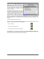
User's Guide - Macintosh Version ® 24 Bit / 96 kHz ü ® SyncAlign ® ZLM PCI Bus Audio Card 2 / 8 Channels Stereo / ADAT® Interface 24 Bit / 96 kHz Digital Audio 32-96 kHz Sample Rate 24 Bit / 96 kHz Analog Audio Board Rev. 1.0, Hardware version 005 Contents 1 2 3 4 5 Introduction .............................................................. 3 Package Contents .................................................... 3 System Requirements .............................................. 3 Brief Description and Characteristics ........................ 3 Technical Specifications 5.1 Digital..................................................................... 4 5.2 Analogue................................................................ 4 5.3 Digital Interface ...................................................... 4 5.4 Transfer Modes: Resolution / Bits per Sample ........ 4 6 Hardware Installation................................................ 5 7 Driver Installation ..................................................... 5 8 Operation and Usage 8.1 Connections............................................................ 7 8.2 Playback................................................................. 7 8.3 Digital Record......................................................... 8 8.4 Analog Record........................................................ 8 8.5 Record while Play................................................... 8 9 Configuring the DIGI96/8 PST 9.1 General .................................................................. 9 9.2 Analog Output ...................................................... 10 9.3 ADAT Mode.......................................................... 10 9.4 Boot Option ADAT ................................................ 10 9.5 Clock Modes - Synchronization............................. 11 10 Using more than one DIGI96/8 PST ............. 12 11 Special Features of the Digital Output .................... 13 12 Operation under ASIO 2.0 12.1 General .............................................................. 14 12.2 Buffer Size - Latency .......................................... 15 12.3 Performance....................................................... 15 12.4 Known problems ................................................. 16 13 Compatibility 13.1 Software ............................................................. 17 13.2 Hardware ............................................................ 17 14 Troubleshooting...................................................... 18 15 Warranty ................................................................ 19 16 Appendix................................................................ 19 User's Guide DIGI96/8 PST © RME 2 1. Introduction Thank you for choosing a RME product. DIGI96/8 PST allows the recording of digital and analog audio from CD, DAT, sampler or other sources directly into your computer. The numerous unique features and well thought-out configuration dialog puts the DIGI96 series at the very top of the range of digital audio interface cards. Drivers for Windows 95/98, Windows NT, BeOS and MacOS allow a problem-free, comfortable and powerful usage on computer systems with PCI bus technology. Drivers for Linux are available both as OSS and ALSA version. This wide choice of drivers makes the DIGI96 series the most versatile cross platform digital audio card available, which may be used under all major Operating Systems. Our 'hi-performance' philosophy guarantees full system performance in all possible functions not carried out by the driver (the computer´s CPU) but carried out by the DIGI96 series hardware. 2. Package Contents Please ensure that all the following parts are included in DIGI96/8 PST’s packaging box: • • • • PCI card DIGI96/8 PST Quick Info guide RME Driver CD Internal cable (2 core) 3. System Requirements • MacOS 8.0 or later • Power Macintosh computer • A free PCI bus slot Additional system requirements such as CPU, memory etc. depend on the software being used for recording, playing and editing the audio data. 4. Brief Description and Characteristics • • • • • • • • • • • • • • Separate record- and playback circuits; complete master mode Enhanced Full Duplex: Different sample rates at input and output possible Mixed mode: ADAT in - SPDIF out and vice versa Automatic and intelligent master/slave clock control Unsurpassed Bitclock-PLL (audio cynchronization) in ADAT mode Optional Word Clock Module (WCM) provides word clock input and output Track Marker Support: Supports CD/DAT Start-IDs and read out of CD subcode ADAT tracks routeable to analog output Unique status windows for record and playback, showing mode and sample rate Realtime ADAT from/to SPDIF converter, realized directly in hardware ASIO 2.0 support Enhanced Zero Latency Monitoring: hardware bypass per track, controlled by Punch-I/O SyncAlign guarantees sample aligned and never swapping channels 32 bit memory transfer and fast 128 kB SRAM guarantee very low system load User's Guide DIGI96/8 PST © RME 3 5. Technical Specifications 5.1 Digital • • • • • • • Ultra-low jitter S/PDIF: < 1 ns in PLL mode (44.1 kHz, optical in) Ultra-low jitter ADAT: < 2 ns in PLL mode (44.1 kHz, optical in) Input PLL ensures zero dropout, even at more than 40 ns jitter Bitclock PLL for trouble-free varispeed in ADAT mode High-sensitivity input stage (< 0.2 Vss input level) Output voltage Consumer 0.8 V, Professional 1.6 V Supported sample rates: 32 / 44.1 / 48 / 64 / 88.2 / 96 kHz and variable (word clock) 5.2 Analog • • • • • • • • Input sensitivity adjustable through jumper +4 dBu / -10 dBV Dynamic range input: 105 dB (RMS unweighted, unmuted), 109 dBA THD+N input: < -100 dB / < 0.001 % Frequency response AD, -0.1 dB: 10 Hz - 20.3 kHz (sf 44,1 kHz) Frequency response AD, -0.5 dB: 5 Hz - 44.8 kHz (sf 96 kHz) Sample rates record: 32 / 44.1 / 48 / 64 / 88.2 / 96 kHz and variable (word clock) Input impedance: 10 kOhm Channel separation: > 110 dB • • • • • • • • Analogue output fixed +10 / +4 / -2 / -8 dBu @ 0 dBFS Dynamic range output: 108 dB (RMS unweighted, unmuted), 112 dBA THD+N output: -100 dB / 0.001% Frequency response DA, -0.1 dB: 20 Hz - 20.8 kHz (sf 44,1 kHz) Frequency response DA, -0.5 dB: 10 Hz - 44 kHz (sf 96 kHz) Sample rates playback: 32 / 44,1 / 48 / 64 / 88,2 / 96 kHz and variable (word clock) Ouput impedance: 75 Ohm Channel separation: > 110 dB 5.3 Digital Interface • Inputs and outputs ground-free transformer coupled • Connectors: optical (TOSLINK), coaxial (phono), internal (CD-ROM/Sync-In, Sync-Out) • Formats: SPDIF, AES/EBU (Consumer/Professional), ADAT optical 5.4 Transfer Modes: Resolution / Bits per Sample • 16 bit 2 bytes (stereo 4 bytes) This mode is active when using the Sound Manager. • 16 bit 2 bytes (stereo 4 bytes) • 32 bit 4 bytes (stereo 8 bytes) These modes are available when using ASIO. The 32 bit mode is used to provide 24 bit audio resolution. User's Guide DIGI96/8 PST © RME 4 6. Hardware Installation Important: Switch off the computer and remove the power cable from the power supply before fitting the DIGI96/8 PST. Inserting and removing the card while the computer is in operation will more than likely lead to irreparable damage to the mainboard! 1. Disconnect the power cord and all other cables from the computer 2. Remove the computer's housing; further information on how to do this can be obtained from your computer´s instruction manual 3. Neutralize the static build up by touching the computer's metal-chassis before unpacking the DIGI96/8 PST from the protective bag. 4. Insert DIGI96/8 PST into a free PCI slot, press and ensure that the card is properly seated. Fasten the screw (if any). 5. Re-place the computer's housing and tighten the screws (if any). 6. Re-connect the power cable and all other cables/connections. 7. Driver Installation The DIGI96/8 PST may be used with Macintosh Sound Manager applications by selecting the card for Input and Output with the Sound Control Panel. When used in this way operation will be restricted to 16 bits and 48 kHz. Full multichannel and 96 kHz performance can only be achieved by using ASIO drivers with ASIO applications. It is not possible to use the DIGI96 series with the control panel 'Monitors and Sound' of MacOS 8.x! This is a restriction of the operating system. Apple provide an optional control panel 'Sound', found in the Apple Extras Folder. Please move this into the Control Panels folder (e.g. by dragging onto the System folder) before installing our card and drivers. MacOS9.x includes a new Sound panel which operates flawlessly with the DIGI96 series. If you already installed an older version of the driver first make sure to remove all old files. To do so open the 'Extensions' folder which is inside your 'System' folder. Remove all files which have a 'DIGI96' at the beginning of their names. Remove every 'DIGI96 ASIO' file from all 'ASIO Drivers' folders of your computer. First fit the card (see 6. Hardware Installation), then switch on the computer and double-click the 'm96_x.sit' archive to decompress it into separate files (using 'Aladin Stuffit Expander'). Drag the new driver DIGI96/8 PAD&PST and the file DIGI96 Sound Component to the System folder. They will be installed automatically into the 'Extension' folder. Confirm the system's message to complete the installation. Now the driver files should be found in the 'Extension' folder, see example to the right. User's Guide DIGI96/8 PST © RME 5 Copy the new files RME DIGI Settings and DIGI96 ASIO into all 'ASIO Drivers' folders found on your computer. As every ASIO software has its own ASIO Drivers folder the files have to be copied several times. The picture to the right shows an example after installation of Hammerfall and DIGI96. Configuration of the DIGI96 series cards is done through the Settings dialog, which can be called from within any ASIO compatible software (for example Audio/System/ASIO Control Panel). To be able to call up the Settings dialog at any time we recommend to create an Alias on the desktop. To create an Alias select 'RME DIGI Settings' with the mouse cursor, press and hold the Apple and Alt keys on your keyboard, and drag 'RME DIGI Settings' to the desired loaction. With this all RME cards in the system can be configured easily even without starting an ASIO software. To finish installation reboot the computer. During re-boot the icon of the driver (a DIGI PCB symbol) appears together with other system extensions, thus signalling three states of installation: • Driver is loading • Driver loaded, hardware found • Driver loading or hardware recognition failed If the DIGI96 driver icon has a red cross through it either driver installation or hardware recognition failed. Try to use a different PCI-slot and check that all driver files are found in the system folder. If that does not work contact your local retailer. User's Guide DIGI96/8 PST © RME 6 8. Operation and Usage 8.1 Connections The DIGI96/8 PST has 2 external and 1 internal (contact pins on the board) inputs and outputs. The internal digital input can be connected to an internal CD-ROM drive when this is supplied with a digital audio output (advantage: the built in CD-ROM drive is sufficient for digital recording and the need for external cabling does not arise). Or it can be connected with the internal output of another DIGI96 series card (synchronizing multiple cards). The current input is selected via the RME DIGI Settings dialog. The card accepts all commonly used digital sources as well as SPDIF and AES/EBU. Channel status and copy protection are ignored. To receive signals in AES/EBU format, an adapter cable is required. Pins 2 and 3 of a female XLR plug are connected individually to the two pins of a phono plug. The cable shielding is only connected to pin 1 of the XLR - not to the phono plug. The ground-free design with transformers for digital inputs and outputs offers a troublefree connection of all devices along with perfect hum rejection. All outputs are driven parallel, therefore carry identical signals. In the simplest situation, connect 2 devices at the outputs and use the card as splitter (distribution 1 to 2). Two ¼" TRS (stereo) jacks are fitted to provide a 2-channel unbalanced analogue input and output. The analog output is directly driven from the digital output. A superior 24 bit DAC followed by a low impedance driver stage allows the connection of stereo headphones. The Settings dialog allows to change the output level from 0 dB down to -78 dB. A special mute circuit reduces noise when switching the computer on and off. The sensitivity of the analog input can be set per channel to +4 dBu or -10 dBV by jumpers on the board. A sensitivity control by driver or Settings dialog is not available. The two connectors ST6 and ST7 provide a connection to the optional Word Clock Module WCM. 8.2 Playback Use the Sound control panel, Sound Out, to activate DIGI96/8 PST as playback device, and set up the desired sample frequency for playback. Note that in most cases it is not necessary to set up the sample rate (and is not possible at all since OS9.x). The Sound Manager will play back all data unaltered as long as the sample rate is supported by the DIGI96 series. Otherwise a software sample rate converter is automatically used. User's Guide DIGI96/8 PST © RME 7 8.3 Digital Record Unlike analog soundcards which produce empty audio files (just noise) when no input signal is present, digital in/out cards must have a valid input signal to start recording. To take this into account, RME has included two unique features in the DIGI96 series: an error LED for the active digital input in use, and a comprehensive I/O signal status display showing sample frequency and lock status. The error LED indicates whether the card gets power and a valid digital input signal. Whenever an error occurs (wrong input, invalid data, signal transmitting device delivers nothing) the LED will light red. As soon as a valid input signal is present the LED will extinguish. The display of the sample frequency (see chapter 9, picture Settings) in the Status display offers a similar function. If no sample frequency can be recognized ‘Out Of Range’ will be shown, in case of an error detection ‘No Lock’. Therefore configuring the software to perform a digital recording is child´s play. After selecting the required input DIGI96/8 PST displays the current sample frequency. This parameter can then be changed in the application’s audio attributes (or similar) dialog. It often makes sense to monitor the input signal or send it directly to the output. The DIGI96 series includes a useful input monitor function, which can be set in the Settings dialog of the DIGI96/8 PST driver (Output/Automatic). Activating Record or Pause in the application causes the input signal to be passed directly to the digital and analog output. Under ASIO this settings has no effect, as the monitoring behaviour is completely handled by the ASIO program itself. To record under Sound Manager select the DIGI96/8 PST as record device in the control panel Sound, Sound In. A click on 'Options' has no effect, further configuration is done through the RME DIGI Settings dialog. Note that the card's input can't be changed in this Sound dialog. This is not a bug but a feature. We have disabled the input selection in all dialogs which call Sound Manager functions. For a better overview the currently active input is displayed. Selecting an input is ONLY done through 'RME DIGI Settings'. 8.4 Analog Record Use the Settings dialog to set the active input to 'Analog' and to activate the line inputs (stereo ¼" TRS jack, wiring diagram see appendix). Two jumpers labelled J2/J3 allow to change the input sensitivity to the most common levels +4 dBu (jumper pulled) and -10 dBV (jumper in place). A full scale level (0 dBFS) requires +19 dBu respectively +2 dBV analog input level. In most cases the factory default -10 dBV proves to be a good choice, because it is highly compatible to many analog devices. 8.5 Record while Play DIGI96/8 PST allows the playback of audio data during the recording of further audio data, even at different sample frequencies. This feature, known as Enhanced Full Duplex or Record while play, is a must for multitrack harddisk recording, but it has to be supported by the recording software. User's Guide DIGI96/8 PST © RME 8 9. Configuring the DIGI96/8 PST 9.1 General The hardware of the DIGI96 series includes a number of helpful, well thought-of practical functions and options, which allow to configure the behaviour of the card to suit many different requirements. Through ‘Settings’ you will gain access to: • • • • • Input selection Output operation Output Channel Status Synchronization behaviour Input and output status display The display of the current input frequency and format is updated every 0.5 seconds. When choosing an input with a signal including errors or without any input signal the statement ‘No Lock’ appears, in vari-speed operation or with sample frequencies widely out of tune ‘Out of Range’ is shown. If the current signal has SPDIF or AES/EBU format then 'Stereo' is displayed, with ADAT format ‘ADAT' is shown. All settings in the dialog are performed in real-time. The three states of the output selected through the choicebox ‘Output’ control the monitoring behaviour of the card. ‘Automatic’ sets the normal mode where the input signal reaches the output only whilst recording. In this mode when starting a recording feedback occurs very often when using digital mixing desks. ‘Play only’ solves this problem by making sure that the input signal is never passed to the output. After selecting ‘Input’ the input signal appears at the output whenever playback is not active. DIGI96/8 PST saves a continual record standby mode and can switch itself to monitoring without active software. As switching between the inputs is carried out in realtime, stepping through the inputs gives a fast check of the incoming signals. Any changes made in the Settings dialog are applied immediately - confirmation (by closing the dialog) is not required. However, settings should not be changed during playback or record if it can be avoided, as this can cause unwanted noises. Also, please note that even in 'Stop' mode, ASIO keep the recording and playback devices open, which means that any new settings might not be applied immediately. In general, we recommend disabling 'Audio active in background’ (assuming this option is available). Specific information about the right choice of the Output Channel Status (output format Consumer / Professional) can be found in chapter 11. User's Guide DIGI96/8 PST © RME 9 9.2 Analog Output Whenever the card's output operates in ADAT format the 2-channel analog output will play back one of the four stereo pairs. The desired pair can be selected in the 'Track' field of the Settings dialog. The analog output level can be set coarse (four 6 dB steps) or fine using the faders in the field 'Volume'. Both methods operate simultaneously and with digital precision. The shown damping values are exactly the ones used. The used technique avoids changes in frequency response and distortion. Only the dynamic range will decrease at higher dampings, as the noise level of the analog output stage remains unchanged. 9.3 ADAT Mode The switch 'Force Adat' is a mighty function of the DIGI96/8 series. It forces the digital output into ADAT mode (i.e. 8-channel operation). The DIGI96 series allows the ADAT optical inputs and outputs to be used with stereo Sound Manager applications. When an ADAT input signal is detected channels 1 and 2 will be automatically used as the Left and Right inputs. When using non ASIO-based audio software to playback a stereo file, the data can be sent over the SPDIF or the ADAT interface! Activating the 'Force ADAT' setting option will change the optical output to be in ADAT format with the stereo signal as tracks 1 and 2. When the DIGI is set to pass through operation (constant monitoring of the input signal by selecting 'Input' mode) it turns into a real-time SPDIF to/from ADAT converter, which operates in hardware without any additional software. In pass through mode activated 'Force Adat' allows to use the card as format converter from SPDIF to ADAT. The stereo signal at the input is copied to all 4 stereo pairs of the output. The switch 'A/S Conv.' forces the card's output into stereo operation. Then the card works as format converter from ADAT to SPDIF. Use the 'Track' buttons to define which one of the 4 stereo input pairs will be routed to the SPDIF output. 9.4 Boot Option ADAT The jumper JP4, labelled 'Boot ADAT', configures the card's state between power-on of the computer and completed boot of the OS. Normally the jumper is set, the card starts in ADAT mode. This option was introduced because several external devices, especially digital mixing desks like Yamaha's 01V or Spirit's 328 will produce noise when an SPDIF signal is present at their ADAT input. The other way round will normally not cause any problem, as most SPDIF and AES/EBU input circuits recognize 'wrong' formats and automatically mute the digital audio signal. To start the card in SPDIF mode simply pull off jumper JP4. User's Guide DIGI96/8 PST © RME 10 9.5 Clock Modes - Synchronization In the digital world, all devices are either the 'Master' (clock source) or a 'Slave' synchronized to the master. Whenever several devices are linked within a system, there must always be a single master. The DIGI96 series includes a very user-friendly intelligent clock control, which handles the clock switching between master and slave on its own. Click on 'AutoSync' to activate this mode. In AutoSync mode, the card constantly scans for a valid input signal at the active input. As soon as this matches the current playback sample rate, the card switches from the internal quartz (display 'Clock Master') to the clock generated from the input signal (display 'Clock Slave'). This allows on-the-fly recording, even during playback, without having to synchronize the card to the input signal first. It also allows immediate playback at any sample rate without having to reconfigure the card. 'AutoSync’ guarantees a fault-free function of the modes Record, Record while Play and while using more than one card (see chapter 10). In certain cases however, e.g. when the inputs and outputs of a DAT machine are connected directly to the DIGI96/8 PST, AutoSync causes feedback in the digital carrier, so synchronization breaks down. To remedy this, switch the card's clock mode over to 'Master'. Due to the outstanding clock control and PLL a synchronization of the output signal to the input signal is not only possible at identical sample rates, but also at double/half sample rates. AutoSync allows multiple cards to be easily synchronized by applying one input signal to all inputs simultaneously (see chapter 10). Thanks to the described AutoSync technology and a lightning fast PLL the DIGI96 Series is not only capable of handling standard frequencies, but also any sample rate between 25 and 102 kHz. The digital input serves as synchronization source. Please note that at the start of a record or playback a valid sample frequency (32 kHz, 44.1 kHz, 48 kHz, 64 kHz, 88.2 kHz, 96 kHz) has to be fed. When started the sample frequency can be pitched to whatever is needed, DIGI96/8 PST will follow theses changes immediately. When using the optional Word Clock Module (clock mode 'Word Clock') the word clock input can serve as synchronization source. In vari-speed operation any sample frequency between 25 kHz and 102 kHz is allowed. Only one device can be master in a digital system! When DIGI96/8 PST operates in clock mode 'Master', all other devices have to be 'Slave'. More information on these subjects can be found in the HTML document 'sync96.htm', located in the directory \rmeaudio.web\english\techinfo on the RME Driver CD, or on our web site. User's Guide DIGI96/8 PST © RME 11 10. Using more than one DIGI96/8 PST The MacOS driver includes support for multiple cards. The driver marks them with different numbers after the device's name, like ‘DIGI96/8 PST In [A1]’. The number is the name of the used PCI slot. Thanks to our AutoSync technology multiple cards can be synchronized easily by applying one input signal to all inputs simultaneously. In order to connect more than one DIGI96/8 PST to a digital mixing desk they must all get the same clock(ed input signal). This is easy to achieve: just connect at least one input of each card to one output of the mixing desk. Example 1: All DIGI's digital inputs are connected to other devices synced to the word clock net. Activate the corresponding input of each card in its Settings dialog, and activate the mode AutoSync at all cards. Example 2: Only the outputs of the DIGIs are connected to other devices. Connect the internal Sync-Out of the master card to the Sync-In (CD-ROM) of the second card, activate its internal input and AutoSync mode. Next connect the third card in the same way, from the second's card Sync-Out to the third's card Sync-In. Configure this card like the second one. The necessary 2-wire cables are the ones supplied with the DIGI cards. Of course this method is also operational with the external connectors, like optical or coaxial, as long as the corresponding input is activated. A convenient alternative is the test mode of the optional Word Clock Module WCM. Please note when using more than one card plus the word clock output that only one card can be master! Example 3: All DIGIs are correctly connected to the Word Clock Module. Activate the test mode by pushing the test switch, so the red LED lights up. Next activate the mode 'Word Clock' in all card's settings dialogs. Now all cards should show 'Word Clock' in the third line of 'Output Status'. After activating the test mode all internally connected cards are immediately synchronized, in case clock mode 'Word Clock' was activated in all settings dialogs. More information on this subject can be found in the HTML document 'sync96.htm', located in the directory \rmeaudio.web\english\techinfo on the RME Driver CD, or on our web site. User's Guide DIGI96/8 PST © RME 12 11. Special Features of the Digital Output Apart from the audio data itself, digital audio signals in SPDIF or AES/EBU format include a header containing Channel Status information. False Channel Status is a common cause of malfunction. The DIGI96 series ignores the received header and creates a totally new one for the output signal. Note that in record or monitor modes, set emphasis bits will disappear. Recordings originally done with emphasis should always be played back with the emphasis bit set! This can be done by selecting the ‘Emphasis’ switch in the Settings dialog. The changes in sound caused by this setting can be monitored in real-time at the analog output jack. At 64, 88.2 and 96 kHz sample rate the analog output does not support De-Emphasis, so no change in sound will be audible. The DIGI96 series new output header is optimized for largest compatibility with other digital devices: • • • • • • • 32 kHz, 44.1 kHz, 48 kHz, 64 kHz, 88.2 kHz, 96 kHz, depending on the current sample rate Audio use, Non-Audio No copyright, copy permitted Format Consumer or Professional Category General, generation not indicated 2-Channel, No Emphasis or 50/15 µs Aux bits audio use Professional AES/EBU equipment can be connected to the DIGI96/8 PST thanks to the transformer-balanced coaxial outputs and the ‘Professional’ format option with doubled output voltage. Output cables should have the same pinout as those used for input (see section 8.1 ‘Connections’), but with a male XLR plug instead of a female one. Note that most consumer-orientated equipment (with optical or phono S/PDIF inputs) will only accept signals in ‘Consumer’ format! The status 'Professional' should always be activated when using AES/EBU format (when the XLR connectors are used). The audio bit in the header can be set to 'Non-Audio'. This is necessary when Dolby AC-3 encoded data is sent to external decoders (surround-sound receivers, television sets etc. with AC3 digital inputs), as these decoders would otherwise not recognize the data as AC-3. When playing back in multi channel mode (using the optical ADAT interface) the XLR and coaxial connectors will be turned off. This prevents sound disturbance by the ADAT signal fed to SPDIF or AES/EBU inputs. User's Guide DIGI96/8 PST © RME 13 12. Operation under ASIO 2.0 12.1 General As Steinberg is the inventor of ASIO we have chosen Steinberg's Cubase VST as example on how to use and setup our cards in ASIO operation. Our ASIO driver supports any combination of cards from the DIGI96 series. Important: Multiple cards MUST be synchronized among themselves! This may be done by using the input signal (having a common clock source, for example a digital mixing desk), several synchronized ADATs or the RME Word Clock Module. Start the ASIO software and select ‘System’ from the Audio menu. Select 'DIGI96 ASIO' as 'ASIO device'. The button 'ASIO Device Control Panel' opens the 'RME DIGI Settings' dialog (see chapter 9, Configuration). Switching between SPDIF (2 channel) and ADAT (8 channel) is done in a very easy and convenient method: Playback: When using more than 2 tracks (Master bus plus at least one other) the card switches into ADAT mode. Simply activate 'Force Adat' in the settings dialog in case the ADAT format is desired when playing back only 2 tracks. Record: The card automatically recognizes ADAT or SPDIF signals and immediately switches into the corresponding mode. It doesn't matter how many inputs are activated. When more than one input is active and a SPDIF signal is present at the input this (stereo) signal will be routed to input 1+2. Mixed Mode: Because of the extended ASIO driver concept it is possible to record from a SPDIF source while playing back in ADAT format and vice versa (Mixed Mode). Under certain configurations sync problems might occur, which make it neccessary to use an external word clock for all participating devices. The Enhanced Zero Latency mode of the DIGI96 series enables the 'ASIO Direct Monitoring' feature of the ASIO 2.0 standard to be used. Please note that in this mode neither routing nor pan are supported so the input signals will only be routed to the same output channel. Other VST mixer settings have no effect. User's Guide DIGI96/8 PST © RME 14 12.2 Buffer Size - Latency The Buffer Size value in the RME DIGI Settings dialog determines the latency (in this case the delay) between the audio application and the DIGI96 series as well as general system stability. The higher the value, the more tracks can be recorded and played back simultaneously and the longer the system takes to react. In RME DIGI Settings, ASIO, 4 different buffer sizes are available: 6 ms 24 bit, 11 ms 16 bit, 23 ms 24 bit and 46 ms 16 bit. There is a simple relationship between the resolution of the ASIO host (Cubase etc.) and the driver. If one of both is set to 16 bit the resolution is limited to 16 bit. Bits 17 to 24 will be truncated. So when the driver uses 16 bit and Cubase is set to 24 bit only 16 bit will be transferred to Cubase. When the driver uses 24 bit and Cubase is set to 16 bit, the additiona information in bits 17 to 24 will be lost. As the real latency depends on the used sample rate the values are different for different sample rates: Choice 46 ms/16 bit 23 ms/32 bit 11 ms/16 bit 6 ms/32 bit Buffer size 2048 s 1024 s 512 s 256 s Resolution 16 bit 32 bit 16 bit 32 bit 44.1 kHz 46.4 ms 23.2 ms 11.6 ms 5.8 ms 48 kHz 42.7 ms 21.3 ms 10.7 ms 5.3 ms 88.2 kHz 23.2 ms 11.6 ms 5.8 ms 2.9 ms 96 kHz 21.3 ms 10.7 ms 5.3 ms 2.7 ms Please note that the given latency describes only one way. The complete path through the computer (record plus playback, monitoring) gives double values. The mode 6 ms often causes crackling and drop outs when used with harddisk based recording, but operates flawlessly when using realtime Synthesizers or pure signal processing (Live Input mode). 11 ms are only recommended in 2 channel operation. Else we STRONGLY recommend to use 46 ms to achieve the highest reliability and security in operation. The 24 bit modes should only be used when really needed, as they not only halve the buffer size (see above), but also produce a higher system load and less reliable system behaviour. 12.3 Performance The 'Audio Performance' settings are especially important. Firstly, the number of channels should be changed to 8, so that all the DIGI96/8 series inputs can be accessed. A very common problem is insufficient hard disk performance. If the first track is missing while recording multiple tracks, or the error message ‘Audio: Record Error’ appears, the disk sub-system is too slow i.e. it is unable to write the audio data to the disk quickly enough. The problem can almost always be remedied by changing ‘Disk Block Buffer Size’ from the default 64kB to 256kB. This is especially true if you want to record more than 8 tracks at the same time (multi-card operation). Recording more than 8 tracks is in most cases only possible after changing ‘Disk Block Buffer Size’ to 256kB (depending on your computer). Please note that these parameters are only updated after clicking on ‘Apply’. The heyday of (expensive) SCSI hard disks in high-speed audio workstations is over. Today’s cheap high-capacity EIDE disks allow continuous transfer rates of well over 5 MB per second. In practical terms, this is more than enough to record far more than 8 simultaneous tracks using Cubase and the DIGI96 series! User's Guide DIGI96/8 PST © RME 15 Working at 96 kHz and 24 bit requires a very fast computer. We recommend at least a G3/400 MHz machine. The reason for this is the very small buffer size in our ASIO driver at this setting. The value 23 ms/32 bit is calculated on 44.1 kHz as base. This means at 96 kHz the effective latency is only 11 ms! At such a low latency the Mac has to be optimized for Low Latency operation, otherwise random click noises will occur. We are currently preparing a Tech Info on this topic, which will be released on our website as soon as it is finished. This ASIO driver works track dependent, it uses only the tracks which were activated. So when using only 4 or 6 record tracks, or no inputs at all (mixdown) please deactivate all unused inputs and outputs to increase performance and reliability. 12.4 Known problems In case the used computer has no sufficient CPU-power and/or sufficient PCI-bus transfer rates, then drop outs, crackling and noise will appear. We also recommend to deactivate all PlugIns to verify that these are not the reason for such effects. Another typical source of trouble is wrong synchronization. ASIO does not support asynchronous operation. This means input and output signal must not only have the same sample frequency, but must also be 'in sync' for error-free Full Duplex operation. See chapter 12.2 for problems with too low latency, caused by 24 bit or 96 kHz operation. User's Guide DIGI96/8 PST © RME 16 13. Compatibility 13.1 Software The DIGI96 series is compatible to all major ASIO applications, like Cubase VST, emagic Logic, Opcode Studio Vision PRO, Prosoniq Sonic WORX, TC SPARK and Peak from Bias. Furthermore there is compatibility to the following programs: Adobe Premier 4.2J Adobe AfterEffect 3.1J Amadeus 1.44 Apple's Movie Player / Quick Time movie player (included with Quick Time 2.5) Coaster 1.03 D-Sound Pro 3.5 (error message, problem with first recording, then ok) MaCthugha 1.0 MelodyAssistant 1.2 / 3.48 ModPlayer 2.11 Player Pro 4.5.9 ProAudioAnalyzer 2.0 Pro Tools / PowerMix 3.4 Rebirth 1.0 SndSampler 3.4 SoundEdit16 1.x / 2.x / Pro SoundSculptor II v2.4.1 SoundTracker 2.0.1 SoundApp 2.5 SoundEffects 0.92 SoundStudio Lite 2.0 SoundMachine 2.1 Sound cdev Super Collider Simple Sound SndSample U and I / Meta synth UltraRecorder VocalWriter 1.0 yaSoundRecorder 13.2 Hardware Blue & White G3, G4 with Sawtooth Board In Yosemite boards (G3) cards of the DIGI96 series do not work in slot 11 (next to the graphics card). In Sawtooth boards (G4) cards of the DIGI96 series do not work in slot 2 (B, next to the graphics card). Athough the system recognizes the card correctly as PCI device no adress is assigned (no configuration write access possible). Therefore the card seems to be installed, but can't be initialized from the OS. Please use the other two PCI slots. General PCI related problems The following symptoms are typical for PCI related problems: • The control panel of the Sound Manager is crossed red • When booting the control panels are displayed too big, or spread across the whole screen • Software or OS crash as soon as the card is used These problems were reported with older computers (prior to G3). They can be solved in most cases by simply using a different slot, or by exchanging slots with other PCI cards (like SCSI controllers or graphics cards). User's Guide DIGI96/8 PST © RME 17 14. Troubleshooting In case the driver icon appears with a red cross after installation of the drivers: • Is the Error LED of the DIGI96/8 PST lit when no cable is connected to the optical input? If not, the card is either defective or not sitting properly in its slot. • The hardware wasn't found because it is not working properly. Try to use the DIGI card in a different PCI slot. The card and drivers have been installed correctly, but playback does not work: • Check that the DIGI96/8 PST has been chosen in the Sound Manager or as ASIO device in the corresponding software. Playback works but recording doesn´t: • Check that there is a valid signal at the input. If so, the Error LED on the hardware extinguishes and the current sample frequency is displayed in the Settings dialog. • If you are sure that a valid signal is being sent but the LED is still red, then check the selected input in the Settings dialog. • Check whether the DIGI96/8 PST has been selected as recording device in the Sound Manager or as ASIO device in the audio application. The recording or the playback is disturbed by crackling: • • • • Lower the system load by using less tracks and turning off some PlugIns. Use different cables (coaxial or optical) to cross-check them for defects. Check that cables have not been connected in a closed loop. If so, set the card’s clock mode to ‘Master’. In case of loop cabling with an ADAT we recommend to use the ADAT as master (Int) and the DIGI as slave (AutoSync). As soon as Logic starts record or playback the digital output of the card is dead: • As soon as the card is used with more than two channels it switches automatically from SPDIF into ADAT mode (see 'Output Status Display' in 'RME DIGI Settings'). To prevent this behaviour limit the maximum numbers of I/O streams in Logic's preferences dialog to two. In Cubase' Master Output window de-activate all busses except the Master. More information and frequently asked questions can be found in the HTML document 'faq96e.htm', located in the directory \rmeaudio.web\english\faq on the RME Driver CD. User's Guide DIGI96/8 PST © RME 18 15. Warranty Each individual DIGI96/8 PST undergoes comprehensive quality control and a complete test in a PC environment at RME before shipping. This may cause very slight signs of wear on the contacts (if the card looks like it was used one time before - it was). The usage of high grade components allows us to offer a full two year warranty. We accept a copy of the sales receipt as valid warranty legitimation. RME’s replacement service within this period is handled by the retailer. If you suspect that your card is faulty, please contact your local retailer. The warranty does not cover damage caused by improper installation or maltreatment - replacement or repair in such cases can only be carried out at the owner’s expense. RME does not accept claims for damages of any kind, especially consequential damage. Liability is limited to the value of the DIGI96/8 PST. The general terms of business drawn up by Synthax OHG apply at all times. 16. Appendix RME news, driver updates and further product information are available on our website: http://www.rme-audio.com If you prefer to read the information off-line, you can load a complete copy of the RME website from the RME Driver CD (in the \rmeaudio.web directory) into your browser. Distributor in Germany: Synthax, Am Pfanderling 62, D-85778 Haimhausen, Tel.: (49) 08133 / 91810 Manufacturer: Ingenieurbuero Mueller, Goethestr. 22, D-09648 Mittweida Trademarks All trademarks and registered trademarks belong to their respective owners. RME, DIGI96, SyncAlign and ZLM are registered trademarks of RME Intelligent Audio Solutions. SyncCheck is a trademark of RME Intelligent Audio Solutions. Alesis and ADAT are registered trademarks of Alesis Corp. ADAT optical is a trademark of Alesis Corp. Apple and MacOS are registered trademarks of Apple Computer Inc. Cubase and VST are registered trademarks of Steinberg Soft- und Hardware GmbH. ASIO is a trademark of Steinberg Soft- und Hardware GmbH. emagic and Logic Audio are registered trademarks of emagic Soft- und Hardware GmbH. Copyright RME, Matthias Carstens, 06/00. Version 1.4 Current driver version: 1.2 This manual applies to board revision 1.0, hardware version 005. Although the contents of this User’s Guide have been thoroughly checked for errors, RME can not guarantee that it is correct throughout. RME does not accept responsibility for any misleading or incorrect information within this guide. Lending or copying any part of the guide or the RME drivers CD, or any commercial exploitation of these media without express written permission from RME Intelligent Audio Solutions is prohibited. RME reserves the right to change specifications at any time without notice. User's Guide DIGI96/8 PST © RME 19 Analog input and output: Pin assignment of the TRS jacks Analog input and output are accessible through stereo ¼" TRS jacks. This allows a direct connection of headphones at the output. In case the output should work as line out an adapter TRS plug to coaxial (phono) plugs, or TRS plug to TS plugs is required. The pin assignment follows international standards. The left channel is connected to the tip, the right channel to the ring of the TRS jack/plug. User's Guide DIGI96/8 PST © RME 20 Block diagram User's Guide DIGI96/8 PST © RME 21 CE This device has been tested and found to comply with the limits of the European Council Directive on the approximation of the laws of the member states relating to electromagnetic compatibility (EMVG) according to EN 55022 class B and EN50082-1. FCC Compliance Statement Certified to comply with the limits for a Class B computing device according to subpart J or part 15 of FCC rules. See instructions if interference to radio reception is suspected. FCC Warning This equipment has been tested and found to comply with the limits for a Class B digital device, pursuant to part 15 of the FCC rules. These limits are designed to provide reasonable protection against harmful interference in a residential installation. This device complies with part 15 of FCC rules. Operation is subject to the following two conditions: 1. This device may not cause harmful interference 2. This device must accept any interference received, including interference that may cause undesired operation. However, there is no guarantee that interference will not occur in a particular installation. If this equipment does cause harmful interference to radio or television reception, which can be determined by turning the equipment off and on, the user is encouraged to try to correct the interference by one or more of the following measures: • Reorient or relocate the receiving antenna • Increase the seperation between the equipment and receiver • Connect the equipment into an outlet on a circuit different from that to which the receiver is connected • Consult the dealer or an experienced radio/TV technician for help. In order for an installation of this product to maintain compliance with the limits for a Class B device, shielded cables must be used for the connection of any devices external to this product. User's Guide DIGI96/8 PST © RME 22