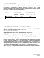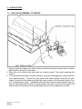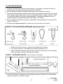
1
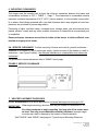
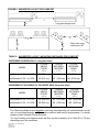
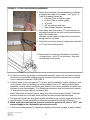
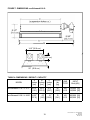
ecoSchwank-X 36, 52 IL-X 150, 200 Gas-Fired Luminous (High Intensity) Infrared Heaters INSTALLATION / OWNER’S MANUAL WARNING Improper installation, adjustment, alteration, service or maintenance can cause property damage, injury or death. Read the installation and operating and maintenance instructions thoroughly before installing or servicing this equipment. Not approved for use in any residential application. SAFETY ALERT: This heater must be installed and serviced only by a trained gas service technician. Failure to comply could result in personal injury, death, fire and/or property damage. Do not store or use gasoline or other flammable vapours and liquids in the vicinity of this or any other gas fired appliance. IF YOU SMELL GAS: Extinguish any open flame Do not attempt to light this or any other appliance Don’t touch any electrical switch, or telephone Immediately leave the area and call your gas supplier from a neighbor’s phone Follow any and all instruction from your gas supplier If your gas supplier is not available, call the fire department FIELD CONVERTIBILITY: This appliance is field convertible to LP gas. Use kit available from manufacturer. See page 14. Follow all local and national codes. INSTALLER: PRESENT THIS MANUAL TO THE END USER. Keep this manual in a secure place . Record for future reference: Model #: Serial #: (located on heater rating label) ECO-X 36-52 / IL-X 150-200 Manual IM100116 RD: MAY 2009 RL: 05A - BA NOTICE: This manual is current for this product. Occasional revision of the product Certification Standard may require changes to the product and/or this manual. This publication, or parts thereof, may not be reproduced in any form, without prior written consent from The Manufacturer. Unauthorized use or distribution of this publication is strictly prohibited. Schwank Group Schwank and InfraSave brands 5285 Bradco Boulevard Mississauga, Ontario,L4W 2A6 PO Box 988, 2 Schwank Way Waynesboro, Georgia 30830 Customer & Technical Services Phone: 877-446-3727 Fax: 866-361-0523 e-mail: [email protected] www.schwankgroup.com www.infrasave.com ECO-X 36-52 / IL-X 150-200 Manual IM100116 RD: MAY 2009 RL: 05A - BA 2 ecoSchwank-X 36, 52 & IL-X 150, 200 GAS FIRED LUMINOUS INFRA-RED HEATERS TABLE OF CONTENTS TOPIC ......... PAGE TOPIC ……...PAGE IMPORTANT INFORMATION - READ FIRST 9. GAS SUPPLY & PIPING ................................ ..14 APPLICATION ............................................. 4 GAS CONVERSION ....................................... 14 HEATER EXPANSION................................. 5 10 ELECTRICAL & THERMOSTAT ...................... 15 GAS CONNECTION............................... 5, 14 VENTING ................................................ 5, 13 11. INSTALLATION .............................................. 16] GAS VALVE ASSEMBLY TO VENTURI......... 16 ‘SMOKE’ & DISCOLORATION ................... 5 HEATER SUSPENSION .................................. 17 CLEARANCE TO COMBUSTIBLES ........... 6 Clearances Figure & Table ....................... 7 STACKING HEIGHT SIGN NEW .............. 8 DIMENSIONS & CAPACITIES ........................ 19 12. LIGHTING INSTRUCTIONS ........................... 20 13. SHUT DOWN INSTRUCTIONS ....................... 20 1. GENERAL APPLICATION ............................... 9 LABOR REQUIREMENTS ............................... 9 14. WIRING DIAGRAM - 24V THERMOSTAT ...... 21 2. INSTALLATION IN AIRCRAFT HANGARS ..... 9 15. WIRING DIAGRAM - 120V THERMOSTAT .... 22 3. INSTALLATION IN COMMERCIAL GARAGES ..................................................... 10 16. SERVICE GUIDE ............................................. 23 4. INSTALLATIONS OTHER THAN SPACE HEATING .......................................... 10 18. HIGH ALTITUDE INSTALLATION ................... 27 17. TROUBLESHOOTING GUIDE ........................ 24 ORIFICE CHART....................................... 27 5. PRE-INSTALLATION SURVEY ..................... 10 19. SEQUENCE OF OPERATION ......................... 28 6. MOUNTING CLEARANCES .......................... 11 20. START– UP / COMMISSIONING SHEET ....... 29 SERVICE CLEARANCE ................................ 11 21. OPTIONAL ACCESSORIES ........................... 31 7. HEATER PLACEMENT GUIDELINES .......... 11 22. PARTS LIST .................................................... 33 8. VENTILATION ............................................... 13 IMPORTANT WARRANTY STATEMENT ............. BACK PAGE Installer: Present this manual to the end user. Acquaint the end user with Important Information: Cover & pages 4 to 8. END USER: In particular you must be aware of ‘Clearances to Combustible’ requirements and the limitations of stacking or placing material near the heaters. Inform your safety personnel and staff of this information. 3 ECO-X 36-52 / IL-X 150-200 Manual IM100116 RD: MAY 2009 RL: 05A - BA IMPORTANT Installer: Present this manual to the end user. Acquaint the end user with Important Information: Cover & pages 4 to 8. END USER: In particular you must be aware of ‘Clearances to Combustible’ requirements and the limitations of stacking or placing material near the heaters. Make your safety personnel and staff aware of this information. WARNING Improper installation, adjustment, alteration, service or maintenance can cause property damage, injury or death. Read and understand this installation and operation manual thoroughly prior to assembly, installation, operation or service to this appliance. This heater must be installed and serviced only by a trained gas service technician. Do not store or use gasoline or other flammable vapours and liquids in the vicinity of this or any other gas fired appliance. Failure to comply could result in personal injury, death, fire and/or property damage. Do not store or use gasoline or other flammable vapours and liquids in the vicinity of this or any other gas fired appliance. This appliance may have sharp edges and corners. Wear protective clothing such as gloves and protective eye wear when servicing this or any other appliance. APPLICATION A gas-fired luminous (high intensity) radiant heater may be installed for heating of commercial / industrial non-residential spaces. It is beyond the scope of these instructions to consider all conditions that may be encountered. Installation must conform with all local building codes or, in the absence of local codes, with the National Fuel Gas Code, ANSI Z223.1/NFPA 54 in the U.S.A. or the Natural Gas and Propane Installation Code, CSA B149.1 in Canada. The latest edition Electrical Code ANSI/NFPA N0 70 in the U.S.A. and PART 1 CSA C22.1 in Canada must also be observed. Installation of a gas-fired radiant heater must conform to all heating installation design procedures including clearance to combustibles, connection to the gas and electrical supplies, and ventilation. This heater is not for installation in a Class 1 or Class 2 explosive environment, nor for any residential application. If installation of this equipment is in question, consult with local authorities having jurisdiction (Fire Marshall, labor department, insurance underwriter, or others). WARNING Revisions to codes and/or standards, may require revision to equipment and installation procedures. In case of discrepancy, the latest codes, standards, and installation manual will take priority over prior releases. IMPORTANT: DO NOT INSTALL THIS HEATER IN A STRUCTURE WITH NO INSULATION IN THE ROOF—CONDENSATION WILL OCCUR. ECO-X 36-52 / IL-X 150-200 Manual IM100116 RD: MAY 2009 RL: 05A - BA 4 WARNING Heater Expansion It is a normal condition that during heat-up and cool-down a radiant heater will expand and contract. Allowances for heater expansion must be made in the gas connection and heater suspension. Improper installation, alteration, or adjustment can result in property damage, injury or death. WARNING Gas Connection Improper installation, connection, or adjustment can result in property damage, toxic gases, asphyxiation, injury or death. Use an approved stainless steel flexible gas connector (field supplied) to connect to the gas supply to the heater in accordance with all local, state, provincial, and national codes (ANSI Z223.1/NFPA 54 in USA; B149.1 in Canada) and as indicated in this manual. WARNING Venting Inadequate venting of a heater may result in asphyxiation, carbon monoxide poisoning, injury or death. This heater is indirectly vented from the space. Venting must be in accordance with all local, state, provincial, and national codes (ANSI Z223.1/NFPA 54 in USA; B149.1 in Canada) and as indicated in this manual. Refer to Sections 11 & 12 WARNING ‘Smoke’ & Discoloration Condition During start-up, the heating of material coatings used in the production process of the heater may create a small amount of smoke during the initial period of operation. This condition is normal and temporary . Ensure that there is sufficient ventilation to adequately clear any ‘smoke’ from the space. Notify site management and safety personnel to ensure that alarm systems are not unduly activated. Under certain conditions in some locations/environments, surface discoloration may occur on the heater body where the products of combustion discharge from the heater. The discoloration is due to the deposit of ambient air borne particulate or gases within the space that have passed through combustion. The combustion of fuel gas in a clean environment will not cause any discoloration. Surface discoloration does not affect the operation or performance of the heater nor the manufacturer’s warranties. 5 ECO-X 36-52 / IL-X 150-200 Manual IM100116 RD: MAY 2009 RL: 05A - BA WARNING Clearance to Combustibles Location of flammable or explosive objects, liquids or vapors close to the heater may cause fire or explosion and result in property damage, injury or death. Do not use, store or locate flammable or explosive objects, liquids or vapors in proximity of the heater. The clearance to combustible material represents the minimum distance that must be maintained between the outer heater surface and a nearby surface. The stated clearance to combustibles represents a surface temperature of 90F° (50C°) above room temperature. It is the installer’s responsibility to ensure that building materials with a low heat tolerance which may degrade at lower temperatures are protected to prevent degradation. In locations used for the storage of combustible materials, signs must be posted to specify the maximum permissible stacking height to maintain the required clearances from the heater to the combustibles. Such signs must either be posted adjacent to the heater thermostats or in the absence of such thermostats in a conspicuous location. In addition to stored or stationary material, consideration must also be given to moveable objects such as cranes, vehicles, and overhead doors, and structural objects such as electrical and gas lines, electrical fixtures, and sprinkler heads. Heaters must be located an appropriate distance from sprinkler heads. This distance may be greater than the certified clearance to combustibles. Check the temperature rating of the sprinkler heads and locate heaters at a safe distance - in some instances the sprinkler heads may need to be replaced by higher temperature heads. It is beyond the scope of these instructions to consider all conditions that may be encountered. Consult local authorities such as the Fire Marshall, insurance carrier, or safety authorities if you are uncertain as to the safety or applicability of the proposed installation. Refer to Figure 1 and Table 1 NEXT PAGE for the certified clearances to combustibles for the appropriate model input/size. ECO-X 36-52 / IL-X 150-200 Manual IM100116 RD: MAY 2009 RL: 05A - BA 6 MOUNTING CLEARANCE TO COMBUSTIBLES NOTE: FOR AREAS USED TO STORE COMBUSTIBLE MATERIAL A ‘PEEL & STICK’ SIGN IS SUPPLIED: USE INDELIBLE MARKER TO RECORD VALUES ‘H’, ‘S’, ‘F’, & ‘B’. POST THE SIGN ADJACENT TO THE HEATER THERMOSTAT OR IN A PROMINENT LOCATION. See next page for details. FIGURE 1: MINIMUM DISTANCES TO COMBUSTIBLES - refer to Table 1 for values SUSPENDED HORIZONTALLY SUSPENDED AT 30° A A F B S S Site distance to floor = T C Max. Stack Height: ‘H’ = T - C Site distance to floor = T Max. Stack Height: ‘H’ = T - C C TABLE 1: MINIMUM CLEARANCE TO COMBUSTIBLES SUSPENDED HORIZONTALLY: Measured from outer surface of heater MODEL BELOW <C> Inches [cm] ecoSchwank-X 36 - IL-X 150 ecoSchwank-X 52 - IL-X 200 121" [307] 121" [307] SIDES TOP ENDS <S> <A> <E> Inches [cm] Inches [cm] Inches [cm] 55” [140] 55” [140] 52" [132] 52" [132] 39" [99] 39" [99] SUSPENDED AT AN ANGLE OF 30° *: Measured from outer surface of heater BELOW FRONT BACK TOP ENDS <C> <F> <B> <A> <E> Inches [cm] Inches [cm] Inches [cm] Inches [cm] Inches [cm] MODEL ecoSchwank-X 36 - IL-X 150 ecoSchwank-X 52 - IL-X 200 121" [307] 121" [307] 84" [213] 84" [213] 55” [140] 55” [140] 52" [132] 52" [132] 39" [99] 39" [99] * NOTE: Suspended between horizontal and 30°: Use the largest clearance from each column ~ See additional notes on previous & next pages ~ 7 ECO-X 36-52 / IL-X 150-200 Manual IM100116 RD: MAY 2009 RL: 05A - BA The clearance to combustible materials represents the minimum distance that must be maintained between the heater and a nearby surface. The stated clearance to combustibles represents a surface temperature of 90F° (50C°) above room temperature. It is the installer’s responsibility to ensure that building materials with a low heat tolerance which may degrade at lower temperatures are protected to prevent degradation. WARNING In locations used for the storage of combustible materials signs must be posted specifying the maximum permissible stacking height to maintain the required clearances from the heater to the combustibles. The signs must be posted either adjacent to the IR heating system thermostats or in the absence of such thermostats, in a conspicuous place. For your convenience a “peel and stick” sign is provided with this heater. Use a permanent marker to record the required dimensions on the sign. To calculate the value ‘H’ ( Maximum Material Stacking Height): Maximum Material Stacking Height: H = T (distance from heater to floor) minus C (the combustibles clearance below the heater) or H = T - C Measure the on-site distance between bottom of the heater and the floor = ‘T’ inches (cm). Refer to Table 1 to get the value ‘C’ (clearance to combustibles below heater) that corresponds to the model you are installing Subtract the clearance below the heater ‘C’ from ‘T’ to get value ‘H’ (maximum material stacking height). Enter this value ‘H’ on the sign with permanent marker. Then, for the heater model/size being installed, refer to the information in Figure 1 and Table 1 to get the values for dimensions ‘S’, ‘F’ and ‘B’ (F and B are for ‘angle mounted’ heaters only). ECO-X 36-52 / IL-X 150-200 Manual IM100116 RD: MAY 2009 RL: 05A - BA 8 Post this sign as instructed above. 1. GENERAL APPLICATION A gas-fired radiant heater may be installed for heating of commercial / industrial non-residential spaces. It is beyond the scope of these instructions to consider all conditions that may be encountered. Installation must conform with all local building codes or, in the absence of local codes, with the National Fuel Gas Code, ANSI Z223.1/NFPA 54 in the U.S.A. or the Natural Gas and Propane Installation Code, CSA B149.1 in Canada. The latest edition Electrical Code ANSI/NFPA N0 70 in the U.S.A. and PART 1 CSA C22.1 in Canada must also be observed. Installation of a gas-fired radiant heater must conform to all heating installation design procedures including clearance to combustibles, connection to the gas and electrical supplies, and ventilation. This heater is not for installation in a Class 1 or Class 2 explosive environment, nor a residence. If installation of this equipment is in question, consult with local authorities having jurisdiction (Fire Marshall, labor department, insurance underwriter, or others). Revisions to codes and/or standards, may require revision to equipment and installation procedures. In case of discrepancy, the latest codes, standards, and installation manual will take priority over prior releases. Models ecoSchwank-X 36, 52 and IL-X 150, 200 may be installed for heating of commercial / industrial non-residential indoor spaces. IMPORTANT: DO NOT INSTALL THIS HEATER IN A STRUCTURE THAT HAS NO INSULATION IN THE ROOF - CONDENSATION WILL OCCUR. This heater cannot be installed inside a degreasing plant, nor in an area where chlorine, fluorine or bromine are present. LABOR REQUIRMENTS Two persons are required to safely install this equipment. Wear gloves and other required safety protection. 2. INSTALLATION IN COMMERCIAL AIRCRAFT HANGARS Luminous (high intensity) radiant tube heaters are suitable for use in aircraft hangars when installed in accordance with the latest edition of the Standard for Aircraft Hangars, ANSI/NFPA No 409 in the USA, or the Canadian Natural Gas and Propane Installation Code, B149.1. A. A minimum clearance of 10 ft (3 m) above either the highest fuel storage compartment or the highest engine enclosure of the highest aircraft which may occupy the hangar. The clearance to the bottom of the heater shall be measured from the upper surface of either the fuel storage compartment or the engine enclosure, whichever is higher from the floor. B. A minimum clearance of 8 ft (2.4 m) must be maintained from the bottom of the heater to the floor in other sections of the aircraft hangar, such as offices and shops, which communicate with areas for servicing or storage. Refer to Table 1 for proper mounting clearances to combustibles. C. Heaters must be located so as to be protected from damage by aircraft and other objects, such as cranes and movable scaffolding. D. Heaters must be located so as to be accessible for servicing and adjustment. 9 ECO-X 36-52 / IL-X 150-200 Manual IM100116 RD: MAY 2009 RL: 05A - BA 3. INSTALLATION IN COMMERCIAL GARAGES AND PARKING STRUCTURES Luminous (high intensity) radiant heaters are suitable for use in commercial garages when installed in accordance with the latest edition of the Standard for Parking Structures, ANSI/NFPA 88A, or the Standard for Repair Garages, ANSI/NFPA No. 88B, or the Canadian Natural Gas and Propane Installation Code, B149.1. WARNING An overhead heater shall be located high enough to maintain the minimum distance to combustibles, as shown on the heater rating plate, from the heater to any vehicles parked below the heater. Overhead heaters shall be installed at least 8 ft (2.4 m) above the floor. 4. INSTALLATIONS OTHER THAN SPACE HEATING Use for process or other applications that are not space heating will void the C.S.A. certification and product warranty. Process application requires field inspection and/or certification by local authorities having jurisdiction. Process application design should be provided by local experienced process design experts. 5. PRE INSTALLATION SURVEY It is recommended that a full heating design including heat loss calculation be conducted on the structure or area to be heated. Heater sizing and placement must consider available mounting height, sources of greatest heat loss, and obstructions on the site. The certified clearances to combustibles with respect to stored material, moveable objects (cranes, vehicles, lifts, overhead doors, etc), structural components, and sprinkler system heads. Consideration must also be given to ventilation fan placement. Carefully survey the area to be heated, and for best results place heaters in the coldest area(s) and at sufficient spacing to provide radiant heat coverage. Installation must conform with all local, state, provincial and national code requirements including the current latest edition ANSI Z223.1 (NFPA 54) in the U.S.A. and B149.1 installation code in Canada, for gas burning appliances and equipment. The latest edition Electrical Code ANSI/NFPA N0 70 in the U.S.A. and PART 1 CSA C22.1 in Canada must also be observed. The heating system must have gas piping of the correct diameter, length, and arrangement to provide for the total system input. A layout drawing is necessary to calculate properly sized gas supply piping. ECO-X 36-52 / IL-X 150-200 Manual IM100116 RD: MAY 2009 RL: 05A - BA 10 6. MOUNTING CLEARANCES This heater must be mounted with at least the minimum clearances between the heater and combustibles as shown in FIG-1, TABLE 1, Page 7. The clearances to combustible material represent a surface temperature of 90 F° (50 C°) above ambient. It is the installer’s responsibility to ensure that building materials with a low heat tolerance which may degrade at lower temperatures are protected to prevent degradation. Positioning of lights, sprinkler heads, overhead doors, storage areas, gas and electrical lines, parked vehicles, cranes and any other possible obstruction or hazard must be evaluated prior to installation. Ensure adequate clearance around the air intake at the burner to allow sufficient combustion air supply to the heater. 6A. SERVICE CLEARANCE: To allow servicing of burner and controls, provide a minimum clearance of 24 inches (61 cm) from the gas supply / ignition-controls of the heater to a wall or obstruction . (see Figure 2 below) - the minimum clearances to combustibles must always be maintained. For guidelines to heater placement refer to TABLE 2 (next page). FIGURE 2: SERVICE CLEARANCE 7. HEATER PLACEMENT GUIDELINES Models ecoSchwank-X & IL-X are approved for horizontal and angle mounting up to 30°. IMPORTANT: When angle mounting, the short axis may be rotated to a maximum of 30°. For either horizontal or angle mounting, the long axis of the heater must be level. Use only non-combustible mounting hardware. Improper angle mounting can result in damage to the heater or unsafe operation. See FIGURE 3 and TABLE 2 next page for ‘Typical Layout Mounting Distances’ 11 ECO-X 36-52 / IL-X 150-200 Manual IM100116 RD: MAY 2009 RL: 05A - BA FIGURE 3: SUGGESTED LAYOUT FOR COMFORT Y Long axis always level X Z Z X Short axis may rotate up to 30° X TABLE 2: SUGGESTED LAYOUT / MOUNTING DISTANCES FOR COMFORT* SUSPENDED HORIZONTALLY: (long axis level) MODEL TYPICAL ABOVE FLOOR <X> TYPICAL BETWEEN HEATERS <Y> TYPICAL BETWEEN ROWS <Z> ecoSchwank-X 36 - IL-X 150 28’ (850 cm) 45' (1375 cm) 85' (2600 cm) ecoSchwank-X 52 - IL-X 200 30' (915 cm) 50' (1525 cm) 90' (2750 cm) SUSPENDED AT AN ANGLE 30° ON SHORT AXIS: (long axis level) MODEL TYPICAL ABOVE FLOOR <X> TYPICAL BETWEEN HEATERS <Y> TYPICAL BETWEEN ROWS <Z> ecoSchwank-X 36 - IL-X 150 26’ (800 cm) 45' (1375 cm) 100' (3050 cm) ecoSchwank-X 52 - IL-X 200 28' (850 cm) 50' (1525 cm) 100' (3050 cm) * The Mounting distances are suggested, and may vary depending on insulation/heat loss values, air movement/change, and other site conditions and comfort requirements. If in doubt, please contact Schwank Design Services. For ‘spot’ heating, the distance above the floor can be reduced by 4 to 6 feet (61 to 132 cm) depending upon site conditions. ECO-X 36-52 / IL-X 150-200 Manual IM100116 RD: MAY 2009 RL: 05A - BA 12 8. VENTILATION WARNING Inadequate venting of a heater may result in asphyxiation, carbon monoxide poisoning, injury or death. Heating system venting must be in accordance with all local, state, provincial, and national codes (ANSI Z223.1/NFPA 54 in USA; B149.1 in Canada). This heater is approved for unvented (indirect venting) application. Ensure that there is adequate ventilation to supply combustion air and to dilute the products of combustion in accordance with all local, state, provincial, and national codes. A balanced exhaust / inlet air system is required to ensure that a negative air condition is not created. See below for a summary of exhaust capacity requirements by the national codes in the U.S.A. and Canada. Air Supply: “Loose” buildings may not require any additional air supply if infiltration rates are sufficient. However, for “tighter” buildings, or if air movement is stagnant in an area, air can typically be supplied via inlet(s) with an area of 1 sq. in. per 1,000 Btuh input (22 sq cm per kW). Locate air inlet(s) up at the level of the heaters to avoid cold drafts at work level, and effectively supply combustion and dilution air to the heaters and balance the system. Heater Zoning: Exhausters are sized according to the input requirements of each controlled zone of heaters. Multiple smaller zones are usually more effective in both comfort and ventilation control than one large zone. Maximum zone size is limited by the total input that can be handled by the capacity of an exhauster, and by the proximity of the exhauster to heaters in the zone. Exhauster Location & Proximity: Exhaust must be located as high as practicable in the structure above the level of the heater(s) to effectively dilute and remove the warm (rising) products of combustion. The exhauster should be as centrally located as practicable in the zone of heaters. Schwank recommends a maximum 6:1 ratio of the horizontal distance between the exhauster and the furthest heater in a zone, to the height the heaters are mounted above the floor . For example, if heaters are mounted 20 ft above the floor, then the exhaust fan should be located no more than 120 ft from the furthest heater in the zone. Sufficient air supply must be provided. Exhauster Capacity: USA: Natural or mechanical means shall be provided to supply and exhaust at least 4ft3/min/1000Btuh (0.38m3/min/kW) Natural Gas input of installed heaters [4.5ft3/ min/1000Btuh (0..43m3/min/kW) Propane input]. Some local codes may require an interlock to a dedicated exhaust fan. Consult your local code and ANSI Z223.1 latest edition for all venting requirements and practices. Canada: It is required that the heater(s) be electrically interlocked to dedicated exhaust fan(s) by means of an Air Proving Switch. Exhaust fan(s) must be sized to create 300 cfm (8.5 cu m/min) exhaust for every 100,000 Btuh (30 kW) or any fraction thereof of total input of installed equipment. Provide combustion and ventilation air supply compatible with exhaust volume . Consult the latest edition of CSA.B149.1 Section 7.22. 13 ECO-X 36-52 / IL-X 150-200 Manual IM100116 RD: MAY 2009 RL: 05A - BA 9. GAS SUPPLY PIPING WARNING Install and connect gas lines in accordance with local, state, provincial and national codes (ANSI Z223.1/NFPA 54 in USA; B149.1 in Canada). Incorrect installation and connection of gas lines may results in fire, explosion, property damage, injury or death Do not install any gas piping or wiring in the heat zone directly above the heater. Do not subject heater controls to leak test pressures when checking the main supply piping. A. Gas piping must be sized to provide adequate input capacity to all heaters and appliances in the system and at the pressure indicated in Table 3 below. IMPORTANT: Minimum supply line pressure at the inlet to the heater regulator must not be lower than 6.0 inches of water column pressure for natural gas and 11” w.c. for propane. The gas supply pressure must be checked with all heaters in operation. B. Provide a 1/8 in (3.2 mm) NPT plugged tapping, accessible for test gauge connection, immediately upstream of the gas supply connection to the heater. C. It is recommended to install an approved flexible connector between the heater and gas piping - available as option from Schwank or from your local supplier. D. A drip-leg prior to the inlet connection to the heater must be provided in the gas line. E. On propane-fired units, a main line filter is recommended. F. Piping joint compounds must be resistant to the action of natural gas or LPG G. TEST FOR LEAKS: Apply soap suds solution to all connections and joints and if bubbles appear, leaks have been detected and must be corrected. DO NOT USE A MATCH OR OPEN FLAME OF ANY KIND TO TEST FOR LEAKS. NEVER OPERATE THE HEATER WITH LEAKING CONNECTIONS. Leak test according to local or national codes. DO NOT use pressure greater than 1/2 psig to pressure check the heater. The supply system should be checked first with heater turned “OFF” followed by another check with heater turned “ON”. WARNING GAS CONVERSION This heater may be field converted from one fuel gas to another (natural gas to or from LPG). Conversion must be accomplished with a kit available from the manufacturer. Contact your local distributor for the kit that is specific to the model installed (SEE PAGE 31). Conversion may include changing of the air restrictor as well as the orifice and gas valve spring. Follow the instructions supplied with the conversion kit. Gas conversion must only be done by a trained gas service technician, according to all local and national codes. Incorrect conversion may result in fire, explosion, property damage, injury or death ECO-X 36-52 / IL-X 150-200 Manual IM100116 RD: MAY 2009 RL: 05A - BA 14 GAS SUPPLY PRESSURE: The maximum supply pressure must be limited to 14 inches w.c. (0.51 psi). If the line pressure is above 14 inches w.c. then a separate pressure reducing regulator must be used - follow all codes. The minimum pressure at the inlet to the heater regulator must be equal to or greater than 6.0 inches w.c. for NG and 11 inches w.c. for LP. A sealed regulator is supplied with the heater which maintains the proper manifold pressure when the main burner is operating under the following pressures: TABLE 3 LINE PRESSURE ( “ w.c.) MANIFOLD PRESSURE inches w.c. AT TAP IN GAS VALVE MINIMUM MAXIMUM NATURAL GAS 6.0 14.0 5.0 PROPANE GAS 11.0 14.0 10.0 10 ELECTRICAL REQUIREMENTS AND THERMOSTAT CONTROL All electrical installations must meet local codes and the latest edition Electrical Code PART 1 CSA C22.1 in Canada and ANSI/NFPA N0 70 in the U.S.A.. TRANSFORMER SPECIFICATIONS Single heater requires 24 Volt, 60 Hz electrical transformer sized at 40 VA. Multiple heaters in a zone are powered by a single transformer. The proper transformer is 24 Volt AC, 60 Hz, sized at 40 VA for the first heater plus 20VA for each additional heater in the zone - round up the calculated value to the next higher available sized transformer. For example, four heaters in a zone require a transformer of : 1 x 40VA + 3 x 20 VA = 100 VA . It is not recommended to install more than 12 heaters per zone. PROPER WIRING POLARITY MUST BE MAINTAINED, particularly when grouping the heaters in a zone. Total wiring distances of up to 200' must use minimum 16 gauge electrical wire, and wiring distances of over 200' must use minimum 14 gauge electrical wire. The heater must be electrically grounded in accordance with local and national electrical codes. Malfunction of the heating system will result if the voltage varies by more than +10% or -10%. The heater can be controlled by a line voltage thermostat, a 24 volt thermostat or “off-on” switch. Total load of all heaters must be considered in determining the required contact rating of the controlling thermostat or switch. 15 ECO-X 36-52 / IL-X 150-200 Manual IM100116 RD: MAY 2009 RL: 05A - BA 11. INSTALLATION 11.1 GAS VALVE ASSEMBLY TO VENTURI 1. Remove valve and heater from carton. Remove the three screws from each venturi collector bell located on one end of the heater. 2. Slide valve onto collector bells and insert two vertical screws. Then install remaining four screws. 3. To avoid possible damage to wiring connection, it may be advantageous to hang heater before connecting wires. Connect two gray wires to the flame sensors located by the electrodes. Connect the two spark-plug type high tension leads to the Electronic Ignition Control. If a thermostat is used, separate the two red wires that are twisted together and connect the thermostat between them. If a thermostat is not used, connect the red wires to the positive side of the power source and the single blue wire to the negative via a switch. ECO-X 36-52 / IL-X 150-200 Manual IM100116 RD: MAY 2009 RL: 05A - BA 16 11.2 HEATER SUSPENSION A. Properly size and install ventilation as per Section 8, gas supply as outlined in Section 9, previous page, and electrical supply as per Section 10 above. B. Ensure adequate clearance around air openings into the combustion chamber C. Suspended infrared heaters shall be fixed in position independent of gas and electric supply lines. Hangers and brackets shall be of non-combustible material. Heaters subject to vibration shall be provided with vibration-isolating hangers. Suspension hardware must be of adequate capacity to support the weight of the heater - see Table 4 D. Mount heaters to structure by using non-combustible mounting hardware such as that illustrated in FIGURE 4. E. Mounting at an angle of up to 30° on short axis (long axis level): see Figure 5 FIGURE 4: TYPICAL MOUNTING HARDWARE (supplied by others) Rotate on the short axis only - long axis must always be horizontal The ‘center of gravity’ of the heater allows angle mounting up to 30° Fasten suspension hardware through holes at each end and each side of the heater body—see Figure 5 below, and Figure 6 next page FIGURE 5: SUSPENDING HEATER - see also Figure 6 next page Long axis always level S S 7/16” (8 mm) holes for suspension hardware 0° to 30° F. Observe the minimum clearances to combustibles as per the Clearance To Combustibles section and Figure 1 and Table 1 page 7. continued ... 17 ECO-X 36-52 / IL-X 150-200 Manual IM100116 RD: MAY 2009 RL: 05A - BA FIGURE 6: ATTACH SUSPENSION HARDWARE 1. Suspension Hardware: Ensure hardware is sufficient to support the weight of the heater - see Figure 7 & Table 4 for heater dimensions #10 Jack Chain or heavier gauge #2 Lion Chain or heavier gauge ‘S’ Hooks 3/8” rod with bolt and nuts Other suitable brackets / hardware 2. Insert open Jack Chain link or ‘S” hook from the outside edge through the top hole at each end and each side of the heater body. Alternate: secure chain to heater with a nut and bolt through the four top holes 3. Use pliers to secure in place by crimping the chain link or ‘S” hook into closed position. 4. Adjust length of suspension hardware for horizontal or angle mount - up to 30° on short axis - long axis must always be horizontal G. In locations used for the storage of combustible materials, signs shall be posted to specify the maximum permissible stacking height to maintain required clearances from the heater to the combustible materials. SEE PAGE 8 H. Connect heater to the main gas line. To absorb gas line expansion, heater expansion, and/ or any vibration from the building it is recommended to use a 1/2" stainless steel flexible connector correctly sized to handle the gas capacity of the heater (available as option from Schwank or your local supplier) . The flexible gas connector must be formed into a smooth ‘C’ shape from the gas supply to the heater inlet. I. Mount thermostat at desired location, away from direct infra-red rays of heater. If the thermostat is located on a cold wall, place sufficient insulation behind the thermostat. J. Test gas line for leaks by using gas pressure test and/or soap test and as per all local and national codes. Ensure gas pressure meets the requirements outlined in Section 9. K. When testing the main gas line pressure, ensure the gas shut-off valve is “OFF”, otherwise damage to the combination gas valve can result. L. Test fire the heating system by following the lighting instructions on page 19 and on heater. ECO-X 36-52 / IL-X 150-200 Manual IM100116 RD: MAY 2009 RL: 05A - BA 18 FIGURE 7: DIMENSIONS: ecoSchwank-X & IL B 14.5” (36.8 cm) 4.75” (12.1 cm) 20” (50.8 cm) TABLE 4: DIMENSIONS / WEIGHT / CAPACITY A Inches [cm] B Inches [cm] C Inches [cm] WEIGHT lbs [kg] GAS TYPE 39.75" [101] 48.5” [123.2] 36.5” [92.7] 65 [29.5] NG LPG 143,000 [42] 143,000 [42] ecoSchwank-X 26 / IL-X100 54.25" [137.8] 63” [160] 51” [129.5] 75 [34.1] NG LPG 200,000 [59] 200,000 [59] MODEL ecoSchwank-X 18 / IL-X 75 19 INPUT Btuh [kW] ECO-X 36-52 / IL-X 150-200 Manual IM100116 RD: MAY 2009 RL: 05A - BA 12. LIGHTING INSTRUCTIONS A Open the isolation valve in the main gas line and turn gas control knob on the combination gas valve to the “ON” position. B Switch on electrical circuit by turning the thermostat to the highest temperature setting. C The heater should attempt ignition and remain lit within thirty seconds. Note that the corresponding exhaust fan is operating properly. D If ignition does not occur, then cut off electrical power by turning the thermostat to off position. E Allow a 5 minute complete shutoff period before relighting the heater WARNING If heater back-fires during operation it must be turned off immediately. Indication of back-firing: A. Loud ignition noise, then followed by distinct hissing sound. B. Little or no visible burning on the ceramic tile. C. Combustion is taking place inside the burner body. Cause & remedy of back-firing: A. Improper gas pressure entering the venturi tube = test & remedy gas pressure. B. Breakage of a ceramic tile and or gasket = replace damaged part. C. Faulty sealing of the ceramic tile to the burner body, caused by breakdown of gasket material = contact your Schwank distributor. 13. SHUT DOWN INSTRUCTIONS A. Turn off electrical circuit for temporary shutdown. B. Turn off the electrical circuit, close gas stop-cock in gas supply line, and turn gas control knob to the “OFF” position for complete shut-down. ECO-X 36-52 / IL-X 150-200 Manual IM100116 RD: MAY 2009 RL: 05A - BA 20 14. ELECTRICAL WIRING DIAGRAM - 24V CONTROL H1 ….. 24 A A2 21 ECO-X 36-52 / IL-X 150-200 Manual IM100116 RD: MAY 2009 RL: 05A - BA 15. ELECTRICAL WIRING DIAGRAM - LINE VOLTAGE (120V) CONTROL H1 ….. A 24 A2 ECO-X 36-52 / IL-X 150-200 Manual IM100116 RD: MAY 2009 RL: 05A - BA 22 16. SERVICE GUIDE Conduct a maintenance inspection of a luminous heater at least annually, prior to the heating season. WARNING Improper adjustment, alteration, service or maintenance can cause property damage, injury or death. This heater must be installed and serviced only by a trained gas service technician. Procedure: 1. Inspect the exhaust fan and all ancillary devices for proper operation and test for leaks at all gas supply connections. Replace worn parts and repair deficiencies. 2. Inspect the integrity of the heater and reflectors. Repair or replace any defective parts. Clean accumulated foreign matter from the reflectors and heater body. 3. During operation: Visually inspect the ceramic burner tiles for cracks A ‘bright’ line on the tile surface indicates a crack in the tile Replace any cracked tile and seating gasket A cracked tile is typically the result of physical impact – inspect the burner body for any additional damage Visually inspect the ceramic burner tiles for blockage by accumulated dust or foreign material A dark spot on the tile surface indicates blockage of the tile. Use low pressure air (less than 20 psig) directed at the tile surface - Avoid directing air stream at the gasket material between tile and heater body. 4. Inspect the venturi tube: Remove any accumulated dust or foreign matter - use low pressure air (less than 20 psig) directed at the venturi. It is important that the flow of combustion air through the venturi not be obstructed. 5. Check the gas supply pressure at the inlet to the gas valve (1/8” NPT tap): Natural Gas: minimum 6.0” w.c. and maximum 14.0” w.c. LPG: minimum 11.0” w.c. and maximum 14.0” w.c. Remedy gas supply condition outside of these specifications. 6. Check the gas supply pressure from the gas valve to the heater manifold (1/8” NPT tap): Natural Gas: 5.0” w.c. LPG: 10” w.c. Remedy manifold pressure condition outside of this specification by adjusting the pressure spring on the gas valve Ensure that the gas valve is operating properly and that no particulate matter is fouling the seating of the valve and allowing gas leakage - replace valve if necessary. 7. Inspect operation of the electronic ignition system: Refer to I&O Manual trouble shooting guide and sections relating to the Spark Ignition and Flame Sensing. 23 ECO-X 36-52 / IL-X 150-200 Manual IM100116 RD: MAY 2009 RL: 05A - BA 17. TROUBLESHOOTING GUIDE SET THERMOSTAT TO CALL FOR HEAT IS THE HEATER BURNING? THE SYSTEM STOP. YES IS WORKING PROPERLY. NO →CHECK FOR DARK SPOTS OR LINES ON THE TILE SURFACE →’DARK’ AREAS REPRESENT CRACKS OR BLOCKAGE OF THE TILE →SEE ’SERVICE’ SECTION 15 IS THERE LINE VOLTAGE (120V) OR 24 VOLTS TO THE THERMOSTAT CONTROL? →CHECK CIRCUIT BREAKERS OR FUSE →CHECK ON/OFF SWITCH →CHECK NIGHT TIME SET BACK CONTROL →CHECK FOR PROPER GAUGE OF WIRE →(24V) CHECK CONTROL CENTER TRANSFORMER. REPLACE IF NECESSARY NO YES IS THERE VOLTAGE (120V) TO THE FAN SYSTEM? →CHECK ELECTRICAL CONNECTION FROM THERMOSTAT TO FAN MOTOR →CHECK THERMOSTAT, REPLACE IF NECESSARY NO YES NO →CHECK EXHAUST FAN MOTOR, REPLACE IF NECESSARY NO →CHECK ELECTRICALCONNECTION TO AIR PROVING SWITCH IS FAN MOTOR OPERATING? YES IS THERE 120 VOLTS TO THE AIR PROVING SWITCH? YES IS THERE 120 VOLTS TO THE TRANSFORMER? YES NO →CHECK ELECTRICAL CONNECTION FROM AIR SWITCH TO TRANSFORMER. →ENSURE AIR SWITCH IS INSTALLED PROPERLY →ENSURE AIR HOSE IS CONNECTED PROPERLY FROM AIR SWITCH TO EXHAUST FAN →CHECK AIR SWITCH, REPLACE IF NECESSARY CONT’D ECO-X 36-52 / IL-X 150-200 Manual IM100116 RD: MAY 2009 RL: 05A - BA 24 IS THERE VOLTAGE (24V) TO IGNITION CONTROL MODULE FROM TRANSFORMER ? →CHECK ELECTRICAL CONNECTION FROM TRANSFORMER TO IGNITION CONTROL MODULE. →CHECK PROPER DISTRIBUTION WIRE GAUGE →ENSURE LOW VOLTAGE WIRES ARE PROPERLY INSTALLED, WIRING POLARITY IS CRITICAL →CHECK VA RATING ON THE TRANSFORMER. 40 VA FOR 1ST HEATER + 20 VA FOR EACH ADDITIONAL HEATER IN THE ZONE. NO YES REFER TO SECTIONS 19 AND 20 BEFORE PROCEEDING →ENSURE THE IGNITER GAP IS 1/4" WIDE (6MM) →ENSURE THE FLAME SENSOR IS WITHIN 1/4” TO 1/8" ABOVE CERAMIC TILE →CHECK SPARK IGNITER CE RAMIC FOR CRACK, REPLACE SPARK IGNITER IF NECES SARY →CHECK HI-VOLTAGE WIRE C O N N E C T I O N FROM SPARK IGNITER TO IGNITION MODULE →ENSURE HIGH VOLTAGE S P A R K S ARE GENERATED ON THE IGNITION CONTROL TERMINAL BY FOLLOWING THE STEPS AS SHOWN BELOW: -SHUT OFF ELECTRICAL POWER -REMOVE THE HI-VOLTAGE WIRE ON THE IGNITION CONTROL TERMINAL IS THERE A SPARK AT IGNITION SPARK IGNITER? NO YES WARNING: BEFORE REMOVING HI-VOLTAGE WIRE, ELECTRICAL POWER TO THE SYSTEM MUST BE SHUT OFF. THIS TERMINAL CARRIES 30,000 AC VOLTS. REFER TO SECTION 20 FOR PROCEDURE CONT’D 25 ECO-X 36-52 / IL-X 150-200 Manual IM100116 RD: MAY 2009 RL: 05A - BA →CHECK ELECTRICAL WIRES FROM IGNITION IS THERE VOLTAGE FROM IGNITION CONTROL TO COMBINATION GAS VALVE? CONTROL TO COMBINATION GAS VALVE →CHECK IGNITION CONTROL, REPLACE IF NO NECESSARY YES IS GAS COMING THROUGH ORIFICE ON THE HEATER? →ENSURE ALL GAS VALVES ARE OPEN NO YES →CHECK SPARK IGNITER FOR CRACKS, DOES THE IGNITION CONTROL TERMINATE THE SPARKING PROCESS AFTER THE HEATER IS OPERATING? REPLACE SPARK IGNITER IF NECESSARY →ENSURE THE SENSING WIRE IS SECURELY CONNECTED TO THE SENSING PROBE →CLEAN THE SENSING PROBE ON THE SPARK IGNITER →ENSURE THE FLAME SENSOR IS WITHIN 1/4" ABOVE THE CERAMIC TILE →CHECK FLAME SIGNAL WITH METER, IF LOW CHANGE SENSOR →REPLACE WITH NEW IGNITION CONTROL UNIT IF OTHER CHECKS ARE OK NO YES DOES HEATER SHUT DOWN AFTER IGNITION CEASES? YES →CHECK FLAME SIGNAL USING A METER INSTALLED IN SERIES WITH SENSOR CABLE, CHECK (MICROAMPS) STRENGTH OF SIGNAL FOR 1.5uA MINIMUM NO STILL HAVING TROUBLE OPERATING THE HEATER? →IF SIGNAL IS LOW REPLACE SENSOR AND WIRE →REPEAT THE ABOVE TROUBLE SHOOTING PROCEDURES →IF THE PROBLEM PERSISTS, CONTACT YOUR SCHWANK DISTRIBUTOR. YES NO TROUBLESHOOTING COMPLETE ECO-X 36-52 / IL-X 150-200 Manual IM100116 RD: MAY 2009 RL: 05A - BA 26 18. HIGH ALTITUDE INSTALLATION This heater not to be installed at altitude above 6,800 feet. USA: The factory installed orifice for this appliance is approved for altitudes zero to 2000 feet above sea level. When installed above 2000 feet, refer to information below. Canada: The factory installed orifice for this appliance is approved for altitudes zero to 4500 feet above sea level. When installed above 4500 feet, refer to information below. When this appliance is installed above the standard altitude stipulated for the USA or Canada, the input must be de-rated by 4% for each 1000 ft above sea level. The orifice must be changed according to the chart below - ensure you search the correct model. Check with your local utility regarding the gas supply and the de-rating of this appliance. NOTE: ecoSchwank-X 36, 52 & IL-X 150, 200 EACH HEATER REQUIRES TWO ORIFICES OF THE SIZE LIST BELOW (ONE FOR EACH BURNER PANEL) FOR USE AT ALTITUDES ABOVE (FEET) 2 Orifices Required - Gas Orifice Drill Size1 / Part# MODEL USA Only USA & CANADA 0 2000 3000 4000 5000 6000 ecoSchwank-X 36 NG IL-X 150 NG 29 DMS JX-0729-DM 29 DMS JX-0729-DM 30 DMS JX-0730-DM 30 DMS JX-0730-DM 30 DMS JX-0730-DM 30 DMS JX-0730-DM ecoSchwank-X 36 LPG IL-X 150 LPG 42 DMS JX-0742-DM 42 DMS JX-0742-DM 43 DMS JX-0743-DM 43 DMS JX-0743-DM 43 DMS JX-0743-DM 44 DMS JX-0744-DM ecoSchwank-X 52 NG IL-X 200 NG 19 DMS JX-0719-DM 20 DMS JX-0720-DM 20 DMS JX-0720-DM 21 DMS JX-0721-DM 22 DMS JX-0722-DM 23 DMS JX-0723-DM ecoSchwank-X 52 LPG IL-X 200 LPG 33 DMS JX-0733-DM 35 DMS JX-0735-DM 35 DMS JX-0735-DM 36 DMS JX-0736-DM 36 DMS JX-0736-DM 37 DMS JX-0737-DM DO NOT INSTALL AT ALTITUDE ABOVE 6,800 FEET 1 Supplied Table values as per ANSI Z223.1 (NFPA 54) 27 ECO-X 36-52 / IL-X 150-200 Manual IM100116 RD: MAY 2009 RL: 05A - BA 19. SEQUENCE OF OPERATION FOR FENWAL DSI CONTROL OPERATION Upon applying power (24VAC) to 24V terminal, the control will reset, perform a self check routine, initiate full time flame sensing, flash the diagnostic LED for up to four seconds, and enter the thermostat scan state. HEAT MODE Upon call for heat from the thermostat, 24 volts is supplied to TH/W, the gas valve is energized and spark commences at both burners for the trial for ignition period (up to 24 seconds total). When flame is detected during trial for ignition, spark is shut off immediately and the gas valve remains energized. The thermostat and burner flame are constantly monitored to assure the system continues to operate properly. When the thermostat is satisfied and the demand for heat ends, the main valve is de-energized immediately. MULTI-TRY IGNITION CONTROL Should either burner fail to light, or flame is not detected during the first trial for ignition period, the gas valve is de-energized and the control goes through an inter-purge delay. The control system will follow this sequence three (3) times before lock out occurs. Recovery from lockout requires a manual reset by either resetting the thermostat or removing 24 volts for a period of 5 seconds. Allow 5 minute shutdown period before relighting the burner. MODE LED INDICATION Internal Control Failure Steady On Start up 1 flash Flame with no call for heat 2 flashes Ignition Lockout 3 flashes Valve relay lockout 4 flashes FLAME FAILURE-RE-IGNITION If the established flame signal is lost from either burner while the burners are operating, the control will respond within 0.8 seconds. After a 5 second inter-purge period, the high voltage spark will be energized for a trial ignition period (remaining time after previous trials - up to 24 seconds total) in an attempt to relight the burners. If either burner does not light the control will de-energize the gas valve. The Multi Try Ignition Control will make two attempts to relight the burners. If either burner does not relight the control will go into lockout as noted above in “Failure to light”. When flame is re-established, normal operation resumes. FLAME FAULT If at any time the main valve fails to close completely and maintain a flame, the full time flame sensing circuit will detect it and flash an error code of 2. FLAME CONDITION - FLAME CURRENT CHECK Flame current is the current which passes through the flame from the sensor to ground. The minimum flame current necessary to keep the system from lockout is .7 microamps. To measure flame current, connect an analog DC micrometer to the FC – FC+ terminals. Meter should read .7 µA or higher. If meter reads below “0” on scale, meter leads are reversed. Disconnect power and reconnect meter leads for proper polarity. ECO-X 36-52 / IL-X 150-200 Manual IM100116 RD: MAY 2009 RL: 05A - BA 28 20. COMMISSIONING REPORT THIS APPLIANCE HAS BEEN FACTORY TESTED PRIOR TO SHIPMENT. HOWEVER, IT IS NOT A “PLUG-IN” APPLIANCE AND REQUIRES FIELD ADJUSTMENT AND COMMISSIONING TO ENSURE SAFE AND EFFICIENT OPERATION. A QUALIFIED GAS SERVICE TECHNICIAN MUST COMMISSION THE APPLIANCE AND COMPLETE THE COMMISSIONING REPORT. CONFIRM THAT THE APPLIANCE IS INSTALLED ACCORDING TO ALL LOCAL AND NATIONAL CODES AND THE INSTRUCTIONS IN THIS MANUAL. ENSURE THAT SITE CONDITIONS MEET THE SPECIFICATIONS IN THIS MANUAL REGARDING: SUSPENSION CLEARANCES TO COMBUSTIBLE MATERIAL VENTING AND AIR SUPPLY ELECTRICAL SUPPLY, WIRING, AND CONNECTION GAS CONNECTION, SUPPLY AND MANIFOLD PRESSURE THIS COMMISSIONING REPORT MUST BE SUBMITTED TO OUR TECHNICAL SERVICES DEPARTMENT PRIOR TO ANY CALL FOR TECHNICAL ASSISTANCE. FAX THE COMPLETED REPORT TO 1-866-361-0523 Call Technical Services: 1-877-446-3727 INSTALLING CONTRACTOR: ……………………………………………………………. COMMISSIONING TECHNICIAN: ……………………………………………………….. ADDRESS: ……………………………………………………………. CITY: ……………………………………………………………. STATE/PROV: ……………………………………………………………. PHONE: ……………………………………………………………. CELL: ……………………………………………………………. DATE INSTALLED: …………………………… PROJECT NAME: ……………………………………………………………. PROJECT CITY: ……………………………………………………………. HEATER MODEL #: ……………………………………………………………. HEATER SERIAL #: ……………………………………………………………. 29 ECO-X 36-52 / IL-X 150-200 Manual IM100116 RD: MAY 2009 RL: 05A - BA TO BE COMPLETED BY THE LICENSED INSTALLER: HIGH INTENSITY LUMINOUS HEATER COMMISSIONING REPORT TYPE OF GAS: NG LP DOES BUILDING HAVE A NEGATIVE CONDITION: YES NO WILL HEATER BE EXPOSED TO WELDING FUMES: YES NO IS HEATER EXPOSED TO CHEMICAL OR CORROSIVE ATMOSPHERE: YES NO IS AN OPEN FLAME COMPATIBLE WITH THE INSTALLED LOCATION: YES NO MINIMUM CLEARANCES CONFORM AS PER I&O MANUAL: YES NO IF THIS IS A HIGH ALTITUDE AREA WHAT IS THE ALTITUDE ABOVE SEA LEVEL Feet SHORTAXIS AXISHORIZONTAL HORIZONTAL(LEVEL) WITH THE VENTURI ON TOP: IS HEATER LONG YES NO IS HEATER INTERLOCKED WITH AN EXHAUST FAN SYSTEM: YES NO IS FAN FAN SYSTEM SYSTEM 3CAPACITY cfm /1000OF Btuh USA; 300 HEAT cfm / 100,000 IS CFM PER (4 1000Btu/hr THE TOTAL LOAD: Btuh YES Canada) CORRECT FOR THE TOTAL HEAT LOAD: NO WILL HEATER BE AFFECTED BY OVERHEAD CRANES / VIBRATION: YES NO IS GAS SUPPLY LINE ADEQUATELY SIZED FOR SYSTEM VOLUME: YES NO HAVE GAS LINES AND BRANCHES BEEN PURGED OF AIR: YES NO THIS HEATER WAS FIELD TEST FIRED WITHOUT ANY MALFUNCTION: YES NO INLET GAS SUPPLY PRESSURE WITH HEATER OPERATING: WC" GAS VALVE OUTLET (Manifold) PRESSURE WITH HEATER OPERATING: WC" HAS THE WIRING POLARITY BEEN MAINTAINED THROUGHOUT: YES WHAT IS THE VOLTAGE READING AT THE IGNITION MODULE: NO VOLTS WHAT IS THE FLAME SIGNAL STRENGTH IN uA FROM SENSOR: uA (microamps) IS THE HEATER CONTROLLED BY A THERMOSTAT: YES NO IS THE THERMOSTAT STRATEGICALY LOCATED: YES NO TOTAL HEATERS SUPPLIED FROM ONE SINGLE TRANSFORMER: WHAT IS THE RATING OF THE TRANSFORMER IN VA: TOTAL V.A. WHAT IS THE TOTAL LENGTH OF THE LOW VOLTAGE WIRING: WHAT IS THE GAUGE OF THE LOW VOLTAGE WIRING: FEET GAUGE THIS HEATER MUST HAVE GOOD ELECTRICAL GROUNDING: 1-866-361-0523 * FAX COMPLETED FORM TO TECHNICAL SERVICES: CANADA - 905-712-8336 USA - 706-554-9390 ECO-X 36-52 / IL-X 150-200 Manual IM100116 RD: MAY 2009 RL: 05A - BA 30 21. OPTIONAL ACCESSORIES GAS CONVERSION KITS: These kits MUST be used for field conversion of heaters from one fuel to the other ecoSchwank 36 / IL 150 NG to LP LP to NG ecoSchwank 52 / IL 200 NG to LP LP to NG Complete installation instructions are supplied with the kit. Line Voltage Thermostat PART # JX-0253-XC-A JX-0252-XC-A JX-0253-XD-A JX-0252-XD-A JL-0772-XX TruTemp Thermostat Senses and averages ambient and radiant temperatures for true comfort control of IR systems Automatic unoccupied setback of 9°F (5°C) - can be overridden JM-0150-XX FOR SECURITY TO PREVENT UNAUTHORIZED OPENING: 2 - Stainless Steel Tamper Proof Screws for TruTemp Thermostat, including 1 Tool. (only one Tool is necessary for most projects) JM-0180-XX 2 - Stainless Steel Tamper Proof Screws for TruTemp Thermostat. (2 for each additional Thermostat on project) JM-0180-AA Low Voltage Digital Thermostat (24 Volts) JS-0569-WR 31 ECO-X 36-52 / IL-X 150-200 Manual IM100116 RD: MAY 2009 RL: 05A - BA Flexible Gas connector 1/2” x 24” JL-0771-XX Pressure Equalizer Venturi Cover For drafty locations (near overhead doors, etc) JO-0368-XX Control Center / Transformer Relay JM-0300-XX AT72D-40VA Transformer for single heater JL-0776-XX Transformer Size ECO-X 36-52 / IL-X 150-200 Manual IM100116 RD: MAY 2009 RL: 05A - BA Heaters Serviced 100 VA Transformer up to 4 JL-0778-XX 150VA Transformer up to 6 JL-0779-XX 200 VA Transformer up to 9 JL-0780-XX 250 va transformer up to 11 JL-0781-XX 350 VA Transformer up to 16 JL-0781-AA 500 VA Transformer up to 24 JL-0781-BB 32 22. PARTS LIST 1 NOTE: ECO 36 / IL 150 IS AN ASSEMBLY OF TWO ECO 18 / IL 75 BURNERS ECO 52 / IL 200 IS AN ASSEMBLY OF TWO ECO 26 / IL 100 BURNERS 33 ECO-X 36-52 / IL-X 150-200 Manual IM100116 RD: MAY 2009 RL: 05A - BA 22. PARTS LIST ecoSchwank-X / IL-X MODELS PART NUMBER PART DESCRIPTION ITEM 1 BURNER BODY ~ INCLUDES TILES MOUNTED IN BODY & ALL REFLECTORS JX-X025-BR ECO-X 6 / IL-X 25: BODY + Mounted TILES + REFLECTORS JX-X037-BR ECO-X 10 / IL-X 37: BODY + Mounted TILES + REFLECTORS JX-X050-BR ECO-X 13 / IL-X 50: BODY + Mounted TILES + REFLECTORS JX-X075-BR ECO-X 18 / IL-X 75: BODY + Mounted TILES + REFLECTORS JX-X100-BR ECO-X 26 / IL-X 100: BODY + Mounted TILES + REFLECTORS JX-X150-BR ECO-X 32 / IL-X 150: BODY + Mounted TILES + REFLECTORS JX-X200-BR ECO-X 52 / IL-X 200: BODY + Mounted TILES + REFLECTORS 2 MAIN BURNER ORIFICE - See chart below 3 VENTURI AERATION RESTRICTOR PLATE (AIR THROTTLE) - See chart below ORIFICE & AIR THROTTLE CHART - ecoSchwank-X / IL-X Model Gas Type -> Input (Btuh) Natural Gas Orifice Part # Air Throttle Part # Propane Gas Orifice Part # Air Throttle Part # ECO-X 6 / IL-X 25 21,500 JX-0748-DM JL-0764-XX JX-0755-DM JL-0764-XX ECO-X 10 / IL-X 37 34,000 JX-0741-DM JO-0373-CC- JX-0752-DM JO-0373-AA- ECO-X 13 / IL-X 50 50,000 JX-0731-DM JO-0373-XX- JX-0747-DM JO-0373-XX- ECO-X 18 / IL-X 75 71,500 JX-0729-DM JO-0375-XX- JX-0742-DM JO-0379-XX- ECO-X 26 / IL-X 100 100,000 JX-0719-DM None JX-0733-DM None ECO-X 36 / IL-X 150 150,000 2 x JX-0729-DM 2 x JO-0375-XX- 2 x JX-0742-DM 2 x JO-0379-XX- 2 x JX-0719-DM None 2 x JX-0733-DM None ECO-X 52 / IL-X 200 4 200,000 JX-0210-XX 5 6 ORIFICE HOLDER - ALL MODELS - ALL SIZES 1", 2" & 2.5" Pipe Nipple - Available at any supply house COMBINATION GAS VALVE JL-0701-XX ECO-X & IL-X N.G. (ALL SIZES) JL-0703-XX ECO-X & IL-X L.P. (ALL SIZES) 7 JX-0206-XX CONTROL BRACKET - ALL MODELS AND SIZES 8 DIRECT SPARK IGNITION CONTROL JX-0202-XX HONEYWELL S87C D.S.I. CONTROL JX-0202-EK REPLACEMENT KIT FOR SYNETEK 3 TRY IGNITION CONTROL - HONEYWELL S87C JX-0201-DD- DSI - FENWAL - TWO BURNER: ECO-X 36, 52 & IL-X 150, 200; Also Includes Wire Harness JX-0201-WH 10 BAFFLE ASSEMBLY - welded integral part - replace burner body if defective 11 GASKET SET JX-0245-AA ECO-X 6 & IL-X 25 JX-0245-XX ECO-X 10 & IL-X 37 JX-0246-XX ECO-X 13 & IL-X 50 + 11a JX-0247-XX ECO-X 18, 36 & IL-X 75, 150 (INCLUDES 11A) + 11a JX-0248-XX ECO-X 26, 52 & IL-X 100, 200 (INCLUDES 11A) 12 JL-0740-XX CERAMIC TILE - ALL MODELS - ALL SIZES 13 Integral tile support - welded to body - not replaceable ECO-X 36-52 / IL-X 150-200 Manual IM100116 RD: MAY 2009 RL: 05A - BA 34 22. PARTS LIST - continued ecoSchwank-X & IL-X MODELS - continued ITEM 14 15 16 PART NUMBER PART DESCRIPTION ECO-X / IL-X / TILE RETAINERS - STAINLESS STEEL - CRIMP-ON JX-0243-XX TILE RETAINER - EACH END - ALL MODELS - ALL SIZES JX-0243-XA TILE RETAINER - 10-7/8" - ECO-X 6 / IL-X 25 & ECO-X 18 & 36 / IL-X 75 & 150 JX-0243-XB TILE RETAINER - 9" - ECO-X 10 / IL-X 37 JX-0243-XC TILE RETAINER - 12-5/8" - ECO-X 13, 18, 26, 36, 52 & IL-X 50, 75, 100, 150, 200 HIGH VOLTAGE WIRE - SPARK JX-0228-XX STANDARD JX-0228-MI PROCESS (HIGH TEMPERATURE WIRE) ECO-X / ECO-MX / IL-X / IL-MX SIDE REFLECTORS (SET OF TWO) JX-0287-XA ECO-X 6 / IL-X 25 JX-0287-XE ECO-X 10 / IL-X 37 JX-0288-XE ECO-X 13 / IL-X 50 JX-0289-XE ECO-X 18 / IL-X 75; ECO-X 36 / IL-X 150 JX-0290-XE ECO-X 26 / IL-X 100; ECO-X 52 / IL-X 200 17 JX-0204-XX IGNITER SENSOR 18 JX-0285-XX IGNITER END REFLECTOR : ECO-X 6 -> 26 & IL-X 25 -> 100 IGNITER END REFLECTOR : ECO-X 36, 52 & IL-X 150, 200 JX-0286-IX19 JX-0286-XX END REFLECTOR : ECO-X 6 -> 26 & IL-X 25 -> 100 JX-0286-BX- END REFLECTOR : ECO-X 36, 52 & IL-X 150, 200 NOT SHOWN - WIRES COMPLETE WITH TERMINALS JX-0229-SR LOW VOLTAGE WIRE - SENSOR JX-0229-MI PROCESS (HIGH TEMPERATURE WIRES) JX-0229-VA LOW VOLTAGE WIRE - VALVE JX-0229-GR LOW VOLTAGE WIRE - GROUND JX-0201-WH WIRE HARNESS - FENWALL - ECO-X 36&52, IL-X 150&200 GAS CONVERSION KITS - SEE CURRENT SCHWANK PRICE LIST 35 ECO-X 36-52 / IL-X 150-200 Manual IM100116 RD: MAY 2009 RL: 05A - BA LIMITED WARRANTY CERTIFICATE GAS-FIRED INFRA-RED LUMINOUS SERIES: ECOSCHWANK ECOSCHWANK-X / IL/ IL-X SERIES SERIES The Manufacturer warrants that this product is free from defects in material or workmanship under normal use and service subject to the terms of this document. TWO YEAR WARRANTY Subject to the conditions and limitations stated herein, during the term of this limited warranty, we will supply any component part (at our option a new or repaired component part) of the heater, as defined below, excluding any labor, which the Manufacturer’s examination determines to be defective in workmanship or material for a period of two years (2 years) from the date of installation, unless otherwise specified below. This warranty applies to the heater’s original owner, and subsequent transferees and only if the unit is installed and operated in accordance with the printed instructions accompanying the unit and in compliance with all applicable installation, building codes and good trade practices. Warranty is only applicable to Schwank components, other parts are limited to their own Manufacturers warranty. (1 year) TEN YEAR WARRANTY The Manufacturer warrants the Ceramic Tiles for a period of ten years (10 years) WHAT IS NOT COVERED The Manufacturer shall not be responsible for any expenses, including service, labor, diagnosis, analysis, material or transportation charges incurred during removal or reinstallation of this product, or any of its components or parts. All labor or service charges shall be paid by the owner. This warranty does not cover heating products improperly installed, misused, exposed to or damaged by negligence, accident, corrosive or contaminating atmosphere, water, excessive thermal shock, impact, abrasion, normal wear due to use, alteration or operation contrary to the owner’s manual or if the serial number has been altered, defaced or removed. This warranty shall not apply if the input to the heating product exceeds by more than 2% of the rated input on the rating plate. The Manufacturer shall not be liable for any default or delay in performance by its warranty caused by any contingency beyond its control, including war, government restrictions, or restraints, strikes, fire, flood, acts of God, or short or reduced supply of raw materials or products. WARRANTY PROCEDURE To establish the installation date for any purpose under this Limited Warranty, you must retain the original records that can establish the installation date of your unit. If you do not provide such documents, the start date of the term of this Limited Warranty will be based upon the date of unit manufacture, plus thirty (30) days. Failure to maintain the equipment through regular annual service maintenance by a qualified service technician shall void the warranty. LIMITATIONS AND EXCLUSIONS This document contains all warranties made by the Manufacturer and may not be varied, altered or extended by any person. There are no promises, or agreements extending from the Manufacture other than the statements contained herein. THIS WARRANTY IS IN LIEU OF ALL WARRANTIES EXPRESSED OR IMPLIED, TO THE EXTENT AUTHORIZED BY THE LAWS OF THE JURISDICTION, INCLUDING SPECIFICALLY THE WARRANTIES OR MERCHANTIBILITY OF FITNESS FOR A PARTICULAR PURPOSE. It is understood and agreed that the Manufacturer’s obligation hereunder is limited to repairing or replacing parts determined to be defective as stated above. In no event shall the Manufacturer be responsible for any alleged personal injuries or other special, incidental or consequential damages. As to property damages, contract, tort or other claim the Manufacturer’s responsibility shall not exceed the purchase priced paid for the product. All replacement parts will be warranted for the unused portion of the warranty coverage period remaining on the applicable unit. Some Authorities do not allow certain warranty exclusions or limitations on how long a warranty lasts or the exclusions or limitations of incidental or consequential damages. In such cases, the above limitations or exclusions may not apply to you and are not intended to do so where prohibited by law. This warranty gives you specific legal rights. You may also have other rights which vary by each jurisdiction. 5285 BRADCO BLVD. MISSISSAUGA, ON, L4W 2A6 2 SCHWANK WAY, WAYNESBORO, GEORGIA. 30830-8336 SCHWANK INFRASAVE ECO-X 36-52 / IL-X 150-200 Manual IM100116 RD: MAY 2009 RL: 05A - BA Ph: 905-712-4766 Fax: 905-712-8336 Ph: 1-866– INFRASV (463 7278) Fax: 1-866-724 –9265 36 GP-DECQ-CX-03B ECO / IL WARRANTY March 2006 RL: 3B KH