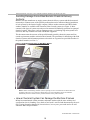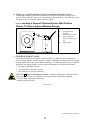
1
Published Manual Number/ECN: MAI36VXXBE/2011092A
• Publishing System: TPAS
• Access date: 2/21/2011
• Document ECN's: Latest Available
Installation—
36021C4E, V5J, V7J
36026V5J, V7J, V7W,
42026V6J, V6W
42030V6J Washer-Extractors
PELLERIN MILNOR CORPORATION
POST OFFICE BOX 400, KENNER, LOUISIANA 70063-0400, U.S.A.
Please Read
About the Manual Identifying Information on the Cover—The front cover displays
pertinent identifying information for this manual. Most important, are the published manual
number (part number) /ECN (date code). Generally, when a replacement manual is furnished, it
will have the same published manual number, but the latest available ECN. This provides the user
with the latest information applicable to his machine. Similarly all documents comprising the
manual will be the latest available as of the date the manual was printed, even though older ECN
dates for those documents may be listed in the table of contents.
When communicating with the Milnor factory regarding this manual, please also provide the
other identifying information shown on the cover, including the publishing system, access date,
and whether the document ECN’s are the latest available or exact.
Best Available Information—This manual contains the most accurate and complete
information available when Milnor shipped your machine/software. Products are occasionally
released with the best available documentation, even though the device identification (model
numbers, etc.) on the documentation does not explicitly include the delivered model. In such
cases, use the documentation provided.
Although unlikely, incorrect manuals may have been shipped with your machine. If you believe
you received the wrong manuals, or if you need specific information about any aspect of your
machine not addressed in the provided documentation, contact the Milnor Customer Service
group.
References to Yellow Troubleshooting Pages—This manual may contain references
to “yellow pages.” Although the pages containing trouble-shooting procedures are no longer
printed on yellow paper, troubleshooting instructions, if any, will be contained in the easily
located “Troubleshooting” section. See the table of contents.
Trademarks of Pellerin Milnor Corporation—The following terms, some of which
may be used in this publication, are trademarks of Pellerin Milnor Corporation:
CBW®
E-P Express®
E-P OneTouch®
E-P Plus®
Gear Guardian®
Mentor®
Mildata®
Milnet®
Milnor®
MultiTrac™
Staph-Guard®
Visionex™
Trademarks of Other Companies—The following terms, some of which may be used in
this publication, are trademarks of their respective companies:
Acronis®
Atlas 2000®
IBM®
Microsoft Windows 2000®
Microsoft Office XP®
Microsoft Windows NT®
Yaskawa®
Microsoft Access®
Microsoft Windows XP®
Comments and Suggestions
Help us to improve this manual by sending your comments to:
Pellerin Milnor Corporation
Attn: Technical Publications
P. O. Box 400
Kenner, LA 70063-0400
Fax: (504) 469-1849
Siemens®
Seagate Crystal Reports®
Table of Contents
for MAI36VXXBE/2011092A
36021C4E, V5J, V7J 36026V5J, V7J, V7W, 42026V6J, V6W 42030V6J Washer-Extractors
Page
Description
Document/ECN
1
3
4
5
10
About This Manual
Limited Standard Warranty
How to Get the Necessary Repair Components
Safety—Rigid Washer Extractors
About the Forces Transmitted by Milnor® Washerextractors
Understanding the Tag Guidelines
Avoiding Damage from Allied Remote Chemical
Delivery Systems
MHI36QXXAE/2007086A
12
16
21
22
26
29
31
33
34
35
36
37
39
41
42
43
44
45
46
47
BMP720097/2008272A
BIUUUD19/20081231
BIUUUS27RU/20051111
BIWUUI02/20001108
BIUUUI02RQ/20110221
BIWUUI03/20030306
Section 1: Installation
Handling and Setting Procedures for CPE, NPE,
Qxx and Vxx Washer-Extractors
Service Connections
MSIN0206AE/2000304V
BIRQVI01AA/20050228
Section 2: Dimensional Drawings
Dimensional Drawing - 36021C4E
Dimensional Drawing - 36021V5J
Dimensional Drawing - 36021V5J (Options)
Dimensional Drawing - 36026V5J
Dimensional Drawing - 36026V5J (Options)
Dimensional Drawing - Pedestal Base 36021/36026V5J
Dimensional Drawing - 36021V7J,V7W
Dimensional Drawing - 36026V7J, V7W
Dimensional Drawing - 36026V7J, V7W Options
Dimensional Drawing - 42026V6J, V6W
Dimensional Drawing - 42026V6J, V6W Options
Dimensional Drawing - 42030V6J
Dimensional Drawing - 42030V6J Options
Dimensional Drawing - Pedestal Base 3621/26V7J,
4226/30V6J
BD3621C4BE/2010163D
BD3621V5BE/2010163D
BD3621V5BB/2008446D
BD3626V5DE/2010163D
BD3626V5DB/2008446D
BD36V5BSBE/2010163D
BD3621V7CE/2007463D
BD3626V7CE/2007463D
BD3626V7CB/2003272D
BD4226V6CE/2007463D
BD4226V6CB/2006412D
BD4230V6AE/2007463D
BD4230V6AB/2006466D
BD42V6BSAE/2007463D
MHI36QXXAE/2007086A (1 of 1)
ABOUT THIS MANUAL
Scope—This instruction manual is intended to provide facility requirements and machine
installation procedures for all Milnor 36021, 36026, 42026 and 42030 model rigid mount
washer-extractors. See the safety manual for safety instructions before installing, servicing, or
operating this machine. See the service manual for preventive maintenance, service procedures,
and mechanical parts identification. See the operator guide for operator instructions. See the
reference manual for programming, operating, and troubleshooting instructions.
Manual Number/Date Code (When To Discard or Save)—The manual
number/date code is located on the inside front cover, upper right corner just above the manual
name. Whenever the manual is reprinted with new information, part of this number changes. If
the date code after the “/” changes, the new version applies to all machines covered by the
old version, but is improved— thus the old version can be discarded. If the manual number
before the “/” changes, the new manual covers only new machines. Example: Discard
MATMODELAE/8739CV when MATMODELAE/8739DV is received (minor improvements).
Also, discard MATMODELAE/8739DV when MATMODELAE/8746AV is received (major
improvements). But keep MATMODELAE/8746FV when MATMODELBE/8815AV is
received, since the new manual no longer applies to machines originally shipped with the old
manual.
Documents and Change Bars—The individual documents comprising this manual use the
same revision criteria as the manual. Text documents also display change bars. Example: When
sectionMSOP0599AE/9135BV becomes MSOP0599AE/9135CV, change bars with the letter
“C” appear next to all changes for this revision. For a major rewrite (e.g.,
MSOP0599AE/9226AV), all change bars are deleted.
For Assistance—Please call:
Pellerin Milnor Corporation
Attn: Service Department
P. O. Box 400
Kenner, LA 70063-0400
Phone:(504) 467-9591
Fax:(504) 467-9777
1
2
PELLERIN MILNOR CORPORATION
LIMITED STANDARD WARRANTY
We warrant to the original purchaser that MILNOR machines including electronic
hardware/software (hereafter referred to as “equipment”), will be free from defects in material and
workmanship for a period of one year from the date of shipment (unless the time period is specifically
extended for certain parts pursuant to a specific MILNOR published extended warranty) from our
factory with no operating hour limitation. This warranty is contingent upon the equipment being
installed, operated and serviced as specified in the operating manual supplied with the equipment,
and operated under normal conditions by competent operators.
Providing we receive written notification of a warranted defect within 30 days of its discovery, we
will at our option repair or replace the defective part or parts, FOB our factory. We retain the right to
require inspection of the parts claimed defective in our factory prior to repairing or replacing same.
We will not be responsible, or in any way liable, for unauthorized repairs or service to our equipment,
and this warranty shall be void if the equipment is tampered with, modified, or abused, used for
purposes not intended in the design and construction of the machine, or is repaired or altered in any
way without MILNOR's written consent.
Parts damaged by exposure to weather, to aggressive water, or to chemical attack are not covered by
this warranty. For parts which require routine replacement due to normal wear such as gaskets,
contact points, brake and clutch linings, belts, hoses, and similar parts the warranty time period is 90
days.
We reserve the right to make changes in the design and/or construction of our equipment (including
purchased components) without obligation to change any equipment previously supplied.
ANY SALE OR FURNISHING OF ANY EQUIPMENT BY MILNOR IS MADE ONLY UPON
THE EXPRESS UNDERSTANDING THAT MILNOR MAKES NO EXPRESSED OR IMPLIED
WARRANTIES OF MERCHANTABILITY OR FITNESS FOR ANY PARTICULAR USE OR
PURPOSE OR ANY OTHER WARRANTY IMPLIED BY LAW INCLUDING BUT NOT
LIMITED TO REDHIBITION. MILNOR WILL NOT BE RESPONSIBLE FOR ANY COSTS OR
DAMAGES ACTUALLY INCURRED OR REQUIRED AS A RESULT OF: THE FAILURE OF
ANY OTHER PERSON OR ENTITY TO PERFORM ITS RESPONSIBILITIES, FIRE OR
OTHER HAZARD, ACCIDENT, IMPROPER STORAGE, MIS-USE, NEGLECT, POWER OR
ENVIRONMENTAL CONTROL MALFUNCTIONS, DAMAGE FROM LIQUIDS, OR ANY
OTHER CAUSE BEYOND THE NORMAL RANGE OF USE. REGARDLESS OF HOW
CAUSED, IN NO EVENT SHALL MILNOR BE LIABLE FOR SPECIAL, INDIRECT,
PUNITIVE, LIQUIDATED, OR CONSEQUENTIAL COSTS OR DAMAGES, OR ANY COSTS
OR DAMAGES WHATSOEVER WHICH EXCEED THE PRICE PAID TO MILNOR FOR THE
EQUIPMENT IT SELLS OR FURNISHES.
THE PROVISIONS ON THIS PAGE REPRESENT THE ONLY WARRANTY FROM MILNOR
AND NO OTHER WARRANTY OR CONDITIONS, STATUTORY OR OTHERWISE, SHALL
BE IMPLIED.
WE NEITHER ASSUME, NOR AUTHORIZE ANY EMPLOYEE OR OTHER PERSON TO
ASSUME FOR US, ANY OTHER RESPONSIBILITY AND/OR LIABILITY IN CONNECTION
WITH THE SALE OR FURNISHING OF OUR EQUIPMENT TOANY BUYER.
BMP720097/2008272A
3
How to Get the Necessary Repair Components
BIUUUD19 (Published) Book specs- Dates: 20081231 / 20081231 / 20081231 Lang: ENG01 Applic: UUU
How to Get the Necessary Repair Components
This document uses Simplified Technical English.
Learn more at http://www.asd-ste100.org.
You can get components to repair your machine from the approved supplier where you got this
machine. Your supplier will usually have the necessary components in stock. You can also get
components from the Milnor® factory.
Tell the supplier the machine model and serial number and this data for each necessary component:
• The component number from this manual
• The component name if known
• The necessary quantity
• The necessary transportation requirements
• If the component is an electrical component, give the schematic number if known.
• If the component is a motor or an electrical control, give the nameplate data from the used
component.
To write to the Milnor factory:
Pellerin Milnor Corporation
Post Office Box 400
Kenner, LA 70063-0400
UNITED STATES
Telephone: 504-467-2787
Fax: 504-469-9777
Email: [email protected]
— End of BIUUUD19 —
PELLERIN MILNOR CORPORATION
4
Safety—Rigid Washer Extractors
BIUUUS27 (Published) Book specs- Dates: 20051111 / 20051111 / 20060322 Lang: ENG01 Applic: RUU
Safety—Rigid Washer Extractors
1.
General Safety Requirements—Vital Information for
Management Personnel [Document BIUUUS04]
Incorrect installation, neglected preventive maintenance, abuse, and/or improper repairs, or
changes to the machine can cause unsafe operation and personal injuries, such as multiple
fractures, amputations, or death. The owner or his selected representative (owner/user) is
responsible for understanding and ensuring the proper operation and maintenance of the machine.
The owner/user must familiarize himself with the contents of all machine instruction manuals.
The owner/user should direct any questions about these instructions to a Milnor® dealer or the
Milnor® Service department.
Most regulatory authorities (including OSHA in the USA and CE in Europe) hold the owner/user
ultimately responsible for maintaining a safe working environment. Therefore, the owner/user
must do or ensure the following:
• recognize all foreseeable safety hazards within his facility and take actions to protect his
personnel, equipment, and facility;
• work equipment is suitable, properly adapted, can be used without risks to health or safety,
and is adequately maintained;
• where specific hazards are likely to be involved, access to the equipment is restricted to those
employees given the task of using it;
• only specifically designated workers carry out repairs, modifications, maintenance, or
servicing;
• information, instruction, and training is provided;
• workers and/or their representatives are consulted.
Work equipment must comply with the requirements listed below. The owner/user must verify
that installation and maintenance of equipment is performed in such a way as to support these
requirements:
• control devices must be visible, identifiable, and marked; be located outside dangerous zones;
and not give rise to a hazard due to unintentional operation;
• control systems must be safe and breakdown/damage must not result in danger;
• work equipment is to be stabilized;
• protection against rupture or disintegration of work equipment;
• guarding, to prevent access to danger zones or to stop movements of dangerous parts before
the danger zones are reached. Guards to be robust; not give rise to any additional hazards; not
be easily removed or rendered inoperative; situated at a sufficient distance from the danger
zone; not restrict view of operating cycle; allow fitting, replacing, or maintenance by
restricting access to relevant area and without removal of guard/protection device;
• suitable lighting for working and maintenance areas;
• maintenance to be possible when work equipment is shut down. If not possible, then
protection measures to be carried out outside danger zones;
• work equipment must be appropriate for preventing the risk of fire or overheating; discharges
of gas, dust, liquid, vapor, other substances; explosion of the equipment or substances in it.
PELLERIN MILNOR CORPORATION
5
Safety—Rigid Washer Extractors
1.1.
Laundry Facility—Provide a supporting floor that is strong and rigid enough to support–with
a reasonable safety factor and without undue or objectionable deflection–the weight of the fully
loaded machine and the forces transmitted by it during operation. Provide sufficient clearance for
machine movement. Provide any safety guards, fences, restraints, devices, and verbal and/or
posted restrictions necessary to prevent personnel, machines, or other moving machinery from
accessing the machine or its path. Provide adequate ventilation to carry away heat and vapors.
Ensure service connections to installed machines meet local and national safety standards,
especially regarding the electrical disconnect (see the National Electric Code). Prominently post
safety information, including signs showing the source of electrical disconnect.
1.2.
Personnel—Inform personnel about hazard avoidance and the importance of care and
common sense. Provide personnel with the safety and operating instructions that apply to them.
Verify that personnel use proper safety and operating procedures. Verify that personnel
understand and abide by the warnings on the machine and precautions in the instruction manuals.
1.3.
Safety Devices—Ensure that no one eliminates or disables any safety device on the machine
or in the facility. Do not allow machine to be used with any missing guard, cover, panel or door.
Service any failing or malfunctioning device before operating the machine.
1.4.
Hazard Information—Important information on hazards is provided on the machine safety
placards, in the Safety Guide, and throughout the other machine manuals. Placards must be kept
clean so that the information is not obscured. They must be replaced immediately if lost or
damaged. The Safety Guide and other machine manuals must be available at all times to
the appropriate personnel. See the machine service manual for safety placard part numbers.
Contact the Milnor Parts department for replacement placards or manuals.
1.5.
2.
Maintenance—Ensure the machine is inspected and serviced in accordance with the norms of
good practice and with the preventive maintenance schedule. Replace belts, pulleys, brake
shoes/disks, clutch plates/tires, rollers, seals, alignment guides, etc. before they are severely
worn. Immediately investigate any evidence of impending failure and make needed repairs (e.g.,
cylinder, shell, or frame cracks; drive components such as motors, gear boxes, bearings, etc.,
whining, grinding, smoking, or becoming abnormally hot; bending or cracking of cylinder, shell,
frame, etc.; leaking seals, hoses, valves, etc.) Do not permit service or maintenance by
unqualified personnel.
Safety Alert Messages—Internal Electrical and Mechanical
Hazards [Document BIUUUS11]
The following are instructions about hazards inside the machine and in electrical enclosures.
WARNING 1 : Electrocution and Electrical Burn Hazards—Contact with electric power
can kill or seriously injure you. Electric power is present inside the cabinetry unless the main
machine power disconnect is off.
• Do not unlock or open electric box doors.
• Do not remove guards, covers, or panels.
• Do not reach into the machine housing or frame.
• Keep yourself and others off of machine.
• Know the location of the main machine disconnect and use it in an emergency to remove
all electric power from the machine.
PELLERIN MILNOR CORPORATION
6
Safety—Rigid Washer Extractors
WARNING 2 : Entangle and Crush Hazards—Contact with moving components normally
isolated by guards, covers, and panels, can entangle and crush your limbs. These components
move automatically.
• Do not remove guards, covers, or panels.
• Do not reach into the machine housing or frame.
• Keep yourself and others off of machine.
• Know the location of all emergency stop switches, pull cords, and/or kick plates and use
them in an emergency to stop machine motion.
3.
Safety Alert Messages—Cylinder and Processing Hazards
[Document BIUUUS13]
The following are instructions about hazards related to the cylinder and laundering process.
DANGER 3 : Entangle and Sever Hazards—Contact with goods being processed can
cause the goods to wrap around your body or limbs and dismember you. The goods are normally
isolated by the locked cylinder door.
• Do not attempt to open the door or reach into the cylinder until the cylinder is stopped.
• Do not touch goods inside or hanging partially outside the turning cylinder.
• Do not operate the machine with a malfunctioning door interlock.
• Know the location of all emergency stop switches, pull cords, and/or kick plates and use
them in an emergency to stop machine motion.
• Know the location of the main machine disconnect and use it in an emergency to remove
all electric power from the machine.
WARNING 4 : Crush Hazards—Contact with the turning cylinder can crush your limbs. The
cylinder will repel any object you try to stop it with, possibly causing the object to strike or stab
you. The turning cylinder is normally isolated by the locked cylinder door.
• Do not attempt to open the door or reach into the cylinder until the cylinder is stopped.
• Do not place any object in the turning cylinder.
• Do not operate the machine with a malfunctioning door interlock.
WARNING 5 : Confined Space Hazards—Confinement in the cylinder can kill or injure
you. Hazards include but are not limited to panic, burns, poisoning, suffocation, heat prostration,
biological contamination, electrocution, and crushing.
• Do not attempt unauthorized servicing, repairs, or modification.
WARNING 6 : Explosion and Fire Hazards—Flammable substances can explode or ignite
in the cylinder, drain trough, or sewer. The machine is designed for washing with water, not any
other solvent. Processing can cause solvent-containing goods to give off flammable vapors.
• Do not use flammable solvents in processing.
• Do not process goods containing flammable substances. Consult with your local fire
department/public safety office and all insurance providers.
PELLERIN MILNOR CORPORATION
7
Safety—Rigid Washer Extractors
4.
4.1.
4.1.1.
Safety Alert Messages—Unsafe Conditions [Document BIUUUS14]
Damage and Malfunction Hazards
Hazards Resulting from Inoperative Safety Devices
DANGER 7 : Entangle and Sever Hazards—Cylinder door interlock—Operating the
machine with a malfunctioning door interlock can permit opening the door when the cylinder is
turning and/or starting the cycle with the door open, exposing the turning cylinder.
• Do not operate the machine with any evidence of damage or malfunction.
WARNING 8 : Multiple Hazards—Operating the machine with an inoperative safety device
can kill or injure personnel, damage or destroy the machine, damage property, and/or void the
warranty.
• Do not tamper with or disable any safety device or operate the machine with a
malfunctioning safety device. Request authorized service.
WARNING 9 : Electrocution and Electrical Burn Hazards—Electric box doors—
Operating the machine with any electric box door unlocked can expose high voltage conductors
inside the box.
• Do not unlock or open electric box doors.
WARNING 10 : Entangle and Crush Hazards—Guards, covers, and panels—Operating
the machine with any guard, cover, or panel removed exposes moving components.
• Do not remove guards, covers, or panels.
4.1.2.
Hazards Resulting from Damaged Mechanical Devices
WARNING 11 : Multiple Hazards—Operating a damaged machine can kill or injure
personnel, further damage or destroy the machine, damage property, and/or void the warranty.
• Do not operate a damaged or malfunctioning machine. Request authorized service.
WARNING 12 : Explosion Hazards—Cylinder—A damaged cylinder can rip apart during
extraction, puncturing the shell and discharging metal fragments at high speed.
• Do not operate the machine with any evidence of damage or malfunction.
WARNING 13 : Explosion Hazards—Clutch and speed switch (multiple motor
machines)—A damaged clutch or speed switch can permit the low speed motor to engage during
extract. This will over-speed the motor and pulleys and can cause them to rip apart, discharging
metal fragments at high speed.
• Stop the machine immediately if any of these conditions occur: • abnormal whining sound
during extract • skidding sound as extract ends • clutches remain engaged or re-engage
during extract
PELLERIN MILNOR CORPORATION
8
Safety—Rigid Washer Extractors
4.2.
4.2.1.
Careless Use Hazards
Careless Operation Hazards—Vital Information for Operator Personnel (see also
operator hazards throughout manual)
WARNING 14 : Multiple Hazards—Careless operator actions can kill or injure personnel,
damage or destroy the machine, damage property, and/or void the warranty.
• Do not tamper with or disable any safety device or operate the machine with a
malfunctioning safety device. Request authorized service.
• Do not operate a damaged or malfunctioning machine. Request authorized service.
• Do not attempt unauthorized servicing, repairs, or modification.
• Do not use the machine in any manner contrary to the factory instructions.
• Use the machine only for its customary and intended purpose.
• Understand the consequences of operating manually.
4.2.2.
Careless Servicing Hazards—Vital Information for Service Personnel (see also
service hazards throughout manuals)
WARNING 15 : Electrocution and Electrical Burn Hazards—Contact with electric
power can kill or seriously injure you. Electric power is present inside the cabinetry unless the
main machine power disconnect is off.
• Do not service the machine unless qualified and authorized. You must clearly understand
the hazards and how to avoid them.
• Abide by the current OSHA lockout/tagout standard when lockout/tagout is called for in
the service instructions. Outside the USA, abide by the OSHA standard in the absence of
any other overriding standard.
WARNING 16 : Entangle and Crush Hazards—Contact with moving components
normally isolated by guards, covers, and panels, can entangle and crush your limbs. These
components move automatically.
• Do not service the machine unless qualified and authorized. You must clearly understand
the hazards and how to avoid them.
• Abide by the current OSHA lockout/tagout standard when lockout/tagout is called for in
the service instructions. Outside the USA, abide by the OSHA standard in the absence of
any other overriding standard.
WARNING 17 : Confined Space Hazards—Confinement in the cylinder can kill or injure
you. Hazards include but are not limited to panic, burns, poisoning, suffocation, heat prostration,
biological contamination, electrocution, and crushing.
• Do not enter the cylinder until it has been thoroughly purged, flushed, drained, cooled,
and immobilized.
— End of BIUUUS27 —
PELLERIN MILNOR CORPORATION
9
BIWUUI02 (Published) Book specs- Dates: 20001108 / 20001108 / 20100609 Lang: ENG01 Applic: WUU
About the Forces Transmitted by Milnor® Washer-extractors
During washing and extracting, all washer-extractors transmit both static and dynamic (cyclic)
forces to the floor, foundation, or any other supporting structure. During washing, the impact of
the goods as they drop imparts forces which are quite difficult to quantify. Size for size, both
rigid and flexibly-mounted machines transmit approximately the same forces during washing.
During extracting, rigid machines transmit forces up to 30 times greater than equivalent flexiblymounted models. The actual magnitude of these forces vary according to several factors:
• machine size,
• final extraction speed,
• amount, condition, and type of goods being processed,
• the liquor level and chemical conditions in the bath preceding extraction, and
• other miscellaneous factors.
Estimates of the maximum force normally encountered are available for each Milnor® model and
size upon request. Floor or foundation sizes shown on any Milnor® document are only for ongrade situations based only on previous experience without implying any warranty, obligation, or
responsibility on our part.
1.
Rigid Machines
Size for size, rigid washer-extractors naturally require a stronger, more rigid floor, foundation, or
other supporting structure than flexibly-mounted models. If the supporting soil under the slab is
itself strong and rigid enough and has not subsided to leave the floor slab suspended without
support, on grade installations can often be made directly to an existing floor slab if it has enough
strength and rigidity to safely withstand our published forces without transmitting undue
vibration. If the subsoil has subsided, or if the floor slab itself has insufficient strength and
rigidity, a deeper foundation, poured as to become monolithic with the floor slab, may be
required. Support pilings may even be required if the subsoil itself is “springy” (i.e., if its
resonant frequency is near the operating speed of the machine). Above-grade installations of rigid
machines also require a sufficiently strong and rigid floor or other supporting structure as
described below.
2.
Flexibly-mounted Machines
Size for size, flexibly-mounted machines generally do not require as strong a floor, foundation, or
other supporting structure as do rigid machines. However, a floor or other supporting structure
having sufficient strength and rigidity, as described in Section 3, is nonetheless vitally important
for these models as well.
3.
How Strong and Rigid?
Many building codes in the U.S.A. specify that laundry floors must have a minimum live load
capacity of 150 pounds per square foot (732 kilograms per square meter). However, even
compliance with this or any other standard does not necessarily guarantee sufficient rigidity. In
any event, it is the sole responsibility of the owner/user to assure that the floor and/or any other
supporting structure exceeds not only all applicable building codes, but also that the floor and/or
any other supporting structure for each washer-extractor or group of washer-extractors actually
has sufficient strength and rigidity, plus a reasonable factor of safety for both, to support the
weight of all the fully loaded machine(s) including the weight of the water and goods, and
including the published 360º rotating sinusoidal RMS forces that are transmitted by the
machine(s). Moreover, the floor, foundation, or other supporting structure must have sufficient
PELLERIN MILNOR CORPORATION
10
About the Forces Transmitted by Milnor® Washer-extractors
rigidity (i.e., a natural or resonant frequency many times greater than the machine speed with a
reasonable factor of safety); otherwise, the mentioned 360º rotating sinusoidal RMS forces can be
multiplied and magnified many times. It is especially important to consider all potential vibration
problems that might occur due to all possible combinations of forcing frequencies (rotating
speeds) of the machine(s) compared to the natural frequencies of the floor and/or any other
supporting structure(s). A qualified soil and/or structural engineer must be engaged for this
purpose.
Figure 1: How Rotating Forces Act on the Foundation
Typical Machine
Legend
A.
B.
C.
Direction of force
Load
Rotation (Frequency = RPM / 60)
.
Figure 1 above is intended to depict both on-grade and above-grade installations and is equally
applicable to flexibly-mounted washer-extractors, as well as to rigid models installed either
directly on a floor slab or on a foundation poured integrally with the slab. Current machine data is
available from Milnor® upon request. All data is subject to change without notice and may have
changed since last printed. It is the sole responsibility of every potential owner to obtain written
confirmation that any data furnished by Milnor® applies for the model(s) and serial number(s) of
the specific machines.
— End of BIWUUI02 —
PELLERIN MILNOR CORPORATION
11
BIUUUI02RQ (Published) Book specs- Dates: 20110221 / 20110221 / 20110221 Lang: ENG01 Applic: RQV 36021C4E
Understanding the Tag Guidelines for the Models Listed Below
36021V5J
42030V6J
36021V7J
36021C4E
36026V5J
36026V7J
36026V7W
42026V6J
42026V6W
Several installation guidelines and precautions are displayed symbolically, on tags placed at the
appropriate locations on the machine. Some are tie-on and others are adhesive tags. Tie-on tags
and white, adhesive tags may be removed after installation. Yellow adhesive tags must remain on
the machine.
PELLERIN MILNOR CORPORATION
12
Understanding the Tag Guidelines for the Models Listed Below
Most tags contain only symbols (no words). A few are worded. The explanations below, start
with the tag part number (displayed on the tag). If a tag contains no words, the meaning of the tag
is explained below. If the tag contains words, the explanation below simply repeats the wording.
Display or Action
Explanation
Read the manual before proceeding. This symbol appears on
most tags. The machine ships with a complete set of manuals.
The safety, installation, and electrical schematic manuals are
particularly important to installers.
B2TAG88005: This carefully built product was tested and
inspected to meet Milnor performance and quality standards by
B2TAG93013: This bearing housing was lubricated at the
Milnor factory before shipment. (This tag not used on 42" V
models.)
B2TAG94078: Do not forklift here; do not jack here; do not step
here—whichever applies.
B2TAG94081: Motor must rotate in this direction. On single
motor washer-extractors and centrifugal extractors, the drive
motor must turn in this direction during draining and extraction.
This tag is usually wrapped around a motor housing. If the motor
turns in the opposite direction when the machine is first tested,
the electrical hookup is incorrect and must be reversed as
explained in the schematic manual.
B2TAG94097: The cylinder must rotate counterclockwise
during draining and extraction (spin) when viewed from here
(rear of machine). Otherwise, reverse the electric power
connections, as explained in the schematic manual.
B2TAG94099: Do not strike the shell door when fork-lifting.
This can cause the door to leak.
PELLERIN MILNOR CORPORATION
13
Display or Action
Explanation
B2T2001013: Hot water connection.
B2T2001014: Cold water connection.
B2T2001015: Reuse (third) water connection.
B2T2001016: Flushing water connection. This is the water that
goes into the supply compartment or pumped chemical manifold
to flush chemicals into the machine.
B2T2001028: Look for tags inside the machine. These tags may
identify shipping restraints to be removed or components to be
installed. Do not start the machine until these actions are
completed.
B2T2002013: Do not start the machine until shipping restraints
are removed. This tag will appear on the outside of the machine
to alert you to the presence of internal shipping restraints. A tag
will also appear on the restraint to help identify it. Most, but not
all shipping restraints display the color red. Some shipping
restraints are also safety stands. Do not discard these.
B2T2003001: Hold the side of the connection stationary with a
wrench as you tighten the connection with another wrench.
Otherwise, you may twist components, such as valves, damaging
them.
PELLERIN MILNOR CORPORATION
14
Understanding the Tag Guidelines for the Models Listed Below
Display or Action
Explanation
B2T2003002: CAUTION: Equipment and Textile Damage
Hazards—Chemicals leaked into the machine, particularly when
it is idle, can destroy machine components and textiles left in the
machine.
Ensure the chemical system prevents dribbling, siphoning, or any
other unintentional release of chemicals.
Inspect regularly for proper operation and evidence of damage.
Consult Milnor document BIWUUI03 “Avoiding Damage from
Allied Remote Chemical Delivery Systems”.
B2T2004027: Steam connection (optional)
B2T2006012: Retain the motor mount spring adjustment sleeve
provided with certain machine models. This sleeve is used to
increase drive belt tension as the belt wears. Instructions are
provided in document BIRQUM01 "Preventive Maintenance" in
the service manual.
— End of BIUUUI02 —
PELLERIN MILNOR CORPORATION
15
BIWUUI03 (Published) Book specs- Dates: 20030306 / 20030306 / 20030306 Lang: ENG01 Applic: WUU
Avoiding Damage From Allied Remote Chemical Delivery
Systems
Milnor® does not manufacture or supply remote chemical delivery systems and this document is
meant only to illustrate some of the possible problems that can be minimized during installation
of such systems by the chemical supply company. Milnor washer-extractors and CBW® batch
washers (tunnels) are available with convenient inlets for such systems (see Figure 1). Most
common of the types of systems currently used in commercial laundering operations are pumped
chemical systems. Other types, such as constant pressure, re-circulating ring main systems have
also been, and may continue to be used with Milnor equipment.
This document warns about some of the possible hazards posed by chemical systems and lists
certain requirements needed to minimize those hazards. The procedures for interfacing with allied
chemical systems and information pertinent to chemical use in general are provided elsewhere in
the product manuals (see Note 1).
Figure 1: Pumped Chemical Inlets on CBW Batch Washer
Note 1: Misuse of laundering chemicals (such as injecting excessive concentrations of chlorine bleach or
permitting acid sours to react with hypo chlorite) due to incorrect formulation can also be hazardous.
Information pertinent to chemical use is provided elsewhere in the product manuals.
1.
How a Chemical System Can Damage the Machine It Serves
Milnor has manufactured washer-extractors and tunnel washers with the same stainless steel
specification since its founding. Every batch of steel used is certified and documented by the steel
mill. Testing of samples damaged by corrosion have, in every case, proven the steel to be well
within the AISI 304 specification.
PELLERIN MILNOR CORPORATION
16
Avoiding Damage From Allied Remote Chemical Delivery Systems
Chemical products commonly found in the laundry industry, when used in established dosages
and proper operating parameters, under the auspices of an experienced chemical specialist, should
produce satisfactory results, with no consequential detrimental effects. The industry has published
standards in Riggs and Sherrill, “Textile Laundering Technology”. However, the stainless steel
can be damaged and even destroyed by abnormal contact with chlorine bleach, hydrofluosilicic
acid and other commonly used chemicals, as will occur if chemicals are unintentionally leaked
into the machine, particularly when it is no longer in use and especially when machine surfaces
are dry.
Some chemical systems have been found to permit chemicals to dribble from the supply lines, or
worse, to siphon from the supply tank into the machine, during operation and long after the
system is shut down—as after working hours and during weekends. If this occurs, deterioration
(rusting) of the stainless steel and damage to any textiles therein will inevitably result. If this
condition goes undetected, machine damage is likely to be catastrophic. No machine is
immune to such damage.
CAUTION 1 : Equipment and Textile Damage Hazards—Chemicals leaked into the
machine, particularly when it is idle can destroy machine components and textiles left in the
machine. Pellerin Milnor Corporation accepts absolutely no responsibility for damage to its
equipment or to textiles therein from abnormal contact with chemicals.
• Ensure that the chemical system prevents unintentional release of chemicals.
• Inspect regularly for proper operation and evidence of damage.
2.
Requirements for Chemical Systems Used With Milnor Machines
It is the responsibility of the chemical system manufacturer and supplier to ensure that their
system is safe for personnel and equipment. Some important points are described below.
2.1.
Ensure the System Cannot Siphon.—The supply system must be designed to
counteract any siphoning that could occur as a result of having a sealed supply line between the
bottom of the chemical tank and the internal machine connection at the drain trough. As shown in
the Figure 2 examples, if the pump (P) and/or the valving does not provide positive closure and
there is no vacuum breaker protection, siphoning is likely to occur. In each of the Figure 2
illustrations, the volume of chemical in the tank above the siphon level (S), and indicated by
shading, will flow into the machine.
PELLERIN MILNOR CORPORATION
17
Figure 2: Siphoning
From the Chemical Tank into the Machine
Examples
Legend
P.
S.
T.
2.2.
Pump
Siphon level. Shading indicates the chemical delivery line and tank content that can siphon into
the machine.
Chemical tank
Ensure the Chemical Lines Cannot Dribble—The pumped chemical system may
provide a means of positively closing the chemical line at the pump location, but not at the
injection site. Hence, any concentrated chemical that remains in the injection line between the
pump and the machine is free to flow into the machine. Some examples of this are shown in
Figure 3.
PELLERIN MILNOR CORPORATION
18
Avoiding Damage From Allied Remote Chemical Delivery Systems
Figure 3: Dribbling
From Chemical Supply Line Into Machine
(assumes positive closure at the pump)
Examples
Legend
D.
P.
T.
3.
Portion of supply line, the contents of which can dribble into the machine
Pump
Chemical tank
Design and Installation Recommendations
It is the responsibility of the chemical system manufacturer and supplier to use whatever
measures are necessary to ensure that their system is safe for personnel and equipment. The
following are some of the possible methods the manufacturer or supplier may wish to use, as
appropriate.
3.1.
Siphoning: Positively close the line.—If the pump does not provide positive closure
when the system is off, employ a shutoff valve in the line to serve this purpose.
3.2.
Siphoning: Break the siphon.—Provide an air gap or vacuum breaker in the chemical
delivery line. This must be located above the “full” line of the tank.
3.3.
Dribbling: Flush the entire chemical delivery line.—If any concentrated chemical
that remains in the injection line between the pump and the machine is free to flow into the
machine, employ a system that flushes the entire line between the pump and the injection point
with fresh water after each injection.
PELLERIN MILNOR CORPORATION
19
3.4.
Dribbling: Locate the entire chemical line below the machine inlet.—
Assuming the chemical system does not retain any line pressure and that the pump provides
positive closure when the system is off, locate the entire chemical delivery line below the level of
the chemical inlet. An example of this is shown in Figure 4.
Figure 4: Locating
a Pumped Chemical System With Positive
Closure To Protect Against Machine Damage
Example of Correct Placement
Legend
I.
L.
P.
T.
4.
Chemical inlet on
machine
Chemical delivery line
Pump with positive
closure when system is
off
Chemical tank
Guarding Against Leaks
All personnel who may work with the chemical system (e.g., chemical system manufacturer,
chemical system supplier, chemical supplier, operator, maintenance personnel) should be vigilant
in observing for leaks in the system. When connecting, or reconnecting chemical lines, whether at
installation, after taking samples, or when replacing components, at a minimum ensure that:
1. the proper components are used,
2. all connections are the proper fit, and
3. all components are securely connected.
CAUTION 2 : Injury and Damage Hazards—Chemicals leaking from a chemical system
may be corrosive or toxic. Such chemicals can injure personnel and damage equipment.
• Use care when connecting chemical lines.
• Inspect regularly for leaks.
— End of BIWUUI03 —
PELLERIN MILNOR CORPORATION
20
Section
Installation
21
1
MSIN0206AE/2000304V
È ANDLING AND SETTING PROCEDURES
H
FOR CPE, NPE, Qxx and Vxx WASHER-EXTRACTORS
Handling Precautions
Ê
1. Remove the protective coverings (leaving the machine on shipping skids) and carefully examine for possible
shipping damage. If machine is damaged, notify the transportation company immediately.
NOTE: Once the machine is given to the carrier for delivery, it is the sole responsibility of the carrier to
ensure that no damage occurs in transit. In addition to readily apparent damage, carriers are liable for concealed damage. Do not hesitate to file a claim with the carrier if the machine is damaged in any way
during shipment. Milnor® will be glad to assist you in filing your claim, but is not responsible for any
shipping damage to the machine once it has been delivered to the carrier in good condition.
2. Permanent lifting rings are provided on some rigid mount machines. Always use these rings for crane lifting.
For machines without permanent lifting rings, consult Milnor® for instructions if crane lifting is required.
3. Use skids with the forklift. If possible, leave the machine on the shipping skids until it is about to be placed in
its final position. Once the skids are removed, take care in placing forks under the machine. Do not allow
the forks to come in contact with valves, piping, motors, etc., located under the machine.
4. Never push, pull, or exert pressure on any components which protrude from the machine frame (shell front,
door, supply injector, electric boxes, controls, belt guards, conduits, inlet piping, etc.).
5. Ensure that the shell door is closed and secured.
6. After installation and before operation, remove the tie wrap that secures the vibration safety switch (located in
the electric control box).
Operational Requirements
Ë
1. Allow sufficient ventilation for heat and vapors of normal operation to dissipate.
2. Provide easy access to controls. Operators must be able to reach and view all status lights, machine controls,
and any additional controls associated with the machine (e.g., electrical power connections, water and steam
shut-offs, etc.).
Foundation Requirements—The machine must be anchored in accordance with the dimensional drawing.
Ë
The floor and/or all other support components must have sufficient strength (and rigidity with due consideration for
the natural or resonant frequency thereof) to withstand the fully loaded weight of the machine, including the wet
goods and any repeated sinusoidal (rotating) forces generated during its operation. Determining the suitability of
floors, foundations, and other supporting structures normally requires analysis by a qualified structural engineer.
See “ABOUT THE FORCES TRANSMITTED BY MILNOR® WASHER-EXTRACTORS” (see Table of Contents) for more information.
Anchoring Requirements
Ê
Machines must be securely anchored to an adequate foundation. Anchor bolt locations and foundation specifications are provided on the dimensional drawing (see Table of Contents). However, never install anchor bolts
firmly in the foundation using only the dimensional drawing or template. Approximate anchor bolt locations
may be determined from a foundation template (standard equipment on some machines, optional on others). Recommended anchor bolt installation (see dimensional drawing) calls for each anchor bolt to be set in a pipe sleeve.
The foundation template or dimensional drawing will only locate the foundation bolts accurately enough that the
play of the bolt within the pipe sleeve permits the machine to fit anchor bolts. If another bolt installation procedure is used, do not install the anchor bolts until the machine is on site and bolt locations can be determined.
Consult Milnor® if any obstruction prevents the installation of any anchor bolt. Anchor bolts cannot be indiscriminately omitted.
Site Requirements
Ê
STRIKE AND MACHINE DAMAGE HAZARDS—A machine can “rip” away from
position on foundation if the machine is not anchored and grouted in strict accordance with the dimensional drawing and setting instructions provided in
this manual. Damage resulting from improper installation is not covered by war
Space Requirements
Ë
1. All openings and corridors through which equipment must pass during installation must be large enough to accommodate the width and the height of the machine (as shown on the dimensional drawing). It is occasionally possible to reduce the overall dimensions by removing piping or other special modifications. Consult
Milnor® for additional information.
ranty.
2. Sufficient clearance must be provided for normal operation and maintenance procedures.
☞ Properly install anchor bolts at ALL anchor bolt holes on the machine.
22
☞ Strictly follow setting instructions and dimensional drawing guidelines when anchoring
and setting this machine.
MSIN0206AE/2000304V
(1 of 2)
È ANDLING AND SETTING PROCEDURES
H
FOR CPE, NPE, Qxx and Vxx WASHER-EXTRACTORS
Handling Precautions
Ê
1. Remove the protective coverings (leaving the machine on shipping skids) and carefully examine for possible
shipping damage. If machine is damaged, notify the transportation company immediately.
NOTE: Once the machine is given to the carrier for delivery, it is the sole responsibility of the carrier to
ensure that no damage occurs in transit. In addition to readily apparent damage, carriers are liable for concealed damage. Do not hesitate to file a claim with the carrier if the machine is damaged in any way
during shipment. Milnor® will be glad to assist you in filing your claim, but is not responsible for any
shipping damage to the machine once it has been delivered to the carrier in good condition.
2. Permanent lifting rings are provided on some rigid mount machines. Always use these rings for crane lifting.
For machines without permanent lifting rings, consult Milnor® for instructions if crane lifting is required.
3. Use skids with the forklift. If possible, leave the machine on the shipping skids until it is about to be placed in
its final position. Once the skids are removed, take care in placing forks under the machine. Do not allow
the forks to come in contact with valves, piping, motors, etc., located under the machine.
4. Never push, pull, or exert pressure on any components which protrude from the machine frame (shell front,
door, supply injector, electric boxes, controls, belt guards, conduits, inlet piping, etc.).
5. Ensure that the shell door is closed and secured.
6. After installation and before operation, remove the tie wrap that secures the vibration safety switch (located in
the electric control box).
Operational Requirements
Ë
1. Allow sufficient ventilation for heat and vapors of normal operation to dissipate.
2. Provide easy access to controls. Operators must be able to reach and view all status lights, machine controls,
and any additional controls associated with the machine (e.g., electrical power connections, water and steam
shut-offs, etc.).
Foundation Requirements—The machine must be anchored in accordance with the dimensional drawing.
Ë
The floor and/or all other support components must have sufficient strength (and rigidity with due consideration for
the natural or resonant frequency thereof) to withstand the fully loaded weight of the machine, including the wet
goods and any repeated sinusoidal (rotating) forces generated during its operation. Determining the suitability of
floors, foundations, and other supporting structures normally requires analysis by a qualified structural engineer.
See “ABOUT THE FORCES TRANSMITTED BY MILNOR® WASHER-EXTRACTORS” (see Table of Contents) for more information.
Anchoring Requirements
Ê
Machines must be securely anchored to an adequate foundation. Anchor bolt locations and foundation specifications are provided on the dimensional drawing (see Table of Contents). However, never install anchor bolts
firmly in the foundation using only the dimensional drawing or template. Approximate anchor bolt locations
may be determined from a foundation template (standard equipment on some machines, optional on others). Recommended anchor bolt installation (see dimensional drawing) calls for each anchor bolt to be set in a pipe sleeve.
The foundation template or dimensional drawing will only locate the foundation bolts accurately enough that the
play of the bolt within the pipe sleeve permits the machine to fit anchor bolts. If another bolt installation procedure is used, do not install the anchor bolts until the machine is on site and bolt locations can be determined.
Consult Milnor® if any obstruction prevents the installation of any anchor bolt. Anchor bolts cannot be indiscriminately omitted.
Site Requirements
Ê
STRIKE AND MACHINE DAMAGE HAZARDS—A machine can “rip” away from
position on foundation if the machine is not anchored and grouted in strict accordance with the dimensional drawing and setting instructions provided in
this manual. Damage resulting from improper installation is not covered by war
Space Requirements
Ë
1. All openings and corridors through which equipment must pass during installation must be large enough to accommodate the width and the height of the machine (as shown on the dimensional drawing). It is occasionally possible to reduce the overall dimensions by removing piping or other special modifications. Consult
Milnor® for additional information.
ranty.
2. Sufficient clearance must be provided for normal operation and maintenance procedures.
☞ Properly install anchor bolts at ALL anchor bolt holes on the machine.
☞ Strictly follow setting instructions and dimensional drawing guidelines when anchoring
and setting this machine.
23
Setting Procedures
Ê
See FIGURE 1 during the following procedures:
Grout must displace total clearance between base plates and existing foundation floor.
☞ Voids must not exist!
1. With the machine near the final location, unbolt the
shipping skids. Observing all precautions, lift the machine off its skids and apply a light coat of grease to
the underside of the right and left side base plates (so
machine can be lifted off of the grout to remove temporary blocking). Lower machine onto temporary
blocking as shown in FIGURE 1. Install anchor
bolts, taking care to align the bolts with the base
plates to avoid bolt thread damage.
2. Determine that the minimum clearance between
each base plate and floor is as specified (see dimensional drawing). Use a carpenter’s level to determine if the machine is level. If necessary, level the
machine from right to left and front to back by shimming at temporary blocking.
☞ If the grout (after mixing) is too thin (causing it to flow from under the base plates) install
temporary cardboard framing around the plates to retain the grout until it cures.
☞ If the grout (after mixing) is of proper consistency, pack or trowel it in by hand.
1. After the grout has cured completely, raise the machine sufficiently to remove all temporary blocking and
shims. Be careful to avoid disturbing or damaging grout.
2. Tighten all fasteners until they contact the top of the base plate.
3. Tighten all fasteners evenly, using only one-quarter turn on each fastener before moving to the next one.
While tightening, frequently skip from front to back and right to left to insure uniform tension. After tightening all fasteners, check each fastener at least twice.
(Qxx shown)
Block at
three points
ÎFIGURE 1 (MSIN0206AE)
ÎBlocking Up Rigid Mount Washer-Extractors
MACHINE DAMAGE AND MALFUNCTION HAZARDS—Never tighten anchor bolt fasteners
before grouting.
☞ Place temporary blocking at the three locations shown in FIGURE 1, not at
four locations to avoid a “teeter-totter” condition.
☞ Tightening anchor bolt fasteners onto spacers (without grout) twists the machine frame
and causes cylinder misalignment.
Preparing to Grout
Ê
All machines are designed to be grouted under the full length of the right and left side base plates (except the
portion that falls over the drain sump). Grout prevents the anchor bolts from distorting the frame when the fasteners
are tightened. Total area under each base plate must be completely filled with grout. Voids under base plates can
magnify vibration, causing unsatisfactory operation. Use only industrial strength non-shrinking grout. Permanently
install the foundation template (if supplied) under the machine as a vapor barrier if the machine is installed over a
drain trough (see the dimensional drawing for additional information). After determining the final position of the
machine, apply grout between the existing foundation floor and base plates, (if utilizing template, see dimensional
drawing for details) while observing the following considerations:
24
Setting Procedures
Ê
See FIGURE 1 during the following procedures:
Grout must displace total clearance between base plates and existing foundation floor.
☞ Voids must not exist!
1. With the machine near the final location, unbolt the
shipping skids. Observing all precautions, lift the machine off its skids and apply a light coat of grease to
the underside of the right and left side base plates (so
machine can be lifted off of the grout to remove temporary blocking). Lower machine onto temporary
blocking as shown in FIGURE 1. Install anchor
bolts, taking care to align the bolts with the base
plates to avoid bolt thread damage.
2. Determine that the minimum clearance between
each base plate and floor is as specified (see dimensional drawing). Use a carpenter’s level to determine if the machine is level. If necessary, level the
machine from right to left and front to back by shimming at temporary blocking.
☞ If the grout (after mixing) is too thin (causing it to flow from under the base plates) install
temporary cardboard framing around the plates to retain the grout until it cures.
☞ If the grout (after mixing) is of proper consistency, pack or trowel it in by hand.
1. After the grout has cured completely, raise the machine sufficiently to remove all temporary blocking and
shims. Be careful to avoid disturbing or damaging grout.
2. Tighten all fasteners until they contact the top of the base plate.
3. Tighten all fasteners evenly, using only one-quarter turn on each fastener before moving to the next one.
While tightening, frequently skip from front to back and right to left to insure uniform tension. After tightening all fasteners, check each fastener at least twice.
(Qxx shown)
Block at
three points
ÎFIGURE 1 (MSIN0206AE)
ÎBlocking Up Rigid Mount Washer-Extractors
MACHINE DAMAGE AND MALFUNCTION HAZARDS—Never tighten anchor bolt fasteners
before grouting.
☞ Place temporary blocking at the three locations shown in FIGURE 1, not at
four locations to avoid a “teeter-totter” condition.
☞ Tightening anchor bolt fasteners onto spacers (without grout) twists the machine frame
and causes cylinder misalignment.
Preparing to Grout
Ê
All machines are designed to be grouted under the full length of the right and left side base plates (except the
portion that falls over the drain sump). Grout prevents the anchor bolts from distorting the frame when the fasteners
are tightened. Total area under each base plate must be completely filled with grout. Voids under base plates can
magnify vibration, causing unsatisfactory operation. Use only industrial strength non-shrinking grout. Permanently
install the foundation template (if supplied) under the machine as a vapor barrier if the machine is installed over a
drain trough (see the dimensional drawing for additional information). After determining the final position of the
machine, apply grout between the existing foundation floor and base plates, (if utilizing template, see dimensional
drawing for details) while observing the following considerations:
25
Service Connections
BIRQVI01 (Published) Book specs- Dates: 20050228 / 20050228 / 20050228 Lang: ENG01 Applic: RQV
Service Connections
1.
General
Required service connections, (depending on machine model and optional features) are as
follows:
1. Piped inlets and outlets (cold water, hot water, flush water, third water, direct steam,
compressed air, liquid supply, and drain to sewer). The sizes and locations of piped inlets and
outlets are shown on the dimensional drawing for your machine.
2. Electrical power connections.
2.
Requirements for Piped Connections
Notice 1 : Machine Damage—Valve bodies will be ruined if twisted and distorted.
• Hold the connection side of the valve with a wrench when connecting plumbing.
1. Inlet pressures must be within the minimum/maximum range specified. Pressure outside of
the specified range may cause the machine to operate inefficiently or malfunction and may
damage machine components.
2. Thoroughly flush all water lines before making connections.
3. We recommend installing 40 mesh strainers or filters in front of the cold, hot and third water
valves.
4. When connecting water and steam inlets, always install unions and shut off valves at the
point of connection to permit removal of the machine components for servicing, when
necessary.
CAUTION 2 : Machine Damage Hazards—Pumped chemical systems, if not properly
installed, can cause corrosion damage.
• See the reference manual for precautions and additional information before making any
chemical connections.
3.
Piped Inlet Specifications
Table 1: Piped Inlets
Connection
Description
Source Requirements
Piping Specifications, Comments
Water valves
36026VxJ - 3/4" NPT @ 10 - 75 psi
42026V6J - 1-1/4" NPT @ 10 - 75 psi
42026V6J only - 1/4" NPT @ 80 - 110 psi
Pipe material per plumbing code
36026V6J - 3/4" NPT @ 30 -115 psi
1/4" NPT (optional) @ 30 - 115 psi
3/8" - 1/2" @ 10 - 75 psi
Pipe material per plumbing code
Pipe material per plumbing code
Flexible tubing as specified by the
chemical supplier
Compressed air
(optional)
Steam inlet
Steam inlet
Liquid supply inlets
Pipe material per plumbing code
PELLERIN MILNOR CORPORATION
26
Service Connections
4.
Piped Outlet Specifications
Piped outlet requirements are as follows (see dimensional drawing for connection sizes and
locations):
Table 2: Outlets
Connection Description
Destination
Piping Specifications
36026VxJ and 42026V6J Drain
3" pipe socket joint, drain to
sewer
Rubber hose, PVC or other
approved material per plumbing
code
5.
Power Connections and Precautions
WARNING 3 : Electrocution and Electrical Burn Hazards—Contact with high voltage
will electrocute or burn you. Power switches on the machine and the control box do not eliminate
these hazards. High voltage is present at the machine unless the main machine power disconnect
is off.
• Do not service machine unless qualified and authorized.
Notice 4 : Machine Damage—Voltage fluctuations of more than 10% above or below the
specified voltage for your machine can damage electrical components, especially motors.
• Any such conditions should be corrected prior to commissioning your machine.
The customer must furnish a remotely mounted disconnect switch with lag type fuses or circuit
breakers, and wiring between the electrical service box and the junction box on the machine. The
sizes of these fuses and wires, along with the motor fuses supplied with the machine, depend on
the machine voltage. See the fuse and wire sizing information in the External Fuse and Wire Size
manual and on the machine nameplate. See dimensional drawings in this manual for electrical
connection locations.
1. Electrical connections must be made by a competent electrician.
2. See fuse and wire sizing information in the External Fuse and Wire Size manual and on the
machine nameplate. If the wire runs more than 50 feet, increase by one wire size for each
additional 50 feet.
3. Only use Bussman Fusatron FRN (up to 250V), FRS (up to 600V) or similar lag fuses, the
nameplate fuse sizes must not be applied to standard fuses.
4. Stinger leg, if any, must be connected to terminal L3, never to terminals L1 or L2.
5. Make power and liquid supply electrical connections within junction boxes on the rear of the
machine.
6. Verify motor rotation (Figure 1). See the operating and trouble shooting manual for more
information. If the cylinder turns in the wrong direction, interchange the wires connected to
L1 and L2. Never move L3 under any circumstances. All motors are phased for proper
rotation. Never attempt to reconnect motors or the motor control devices.
7. Machine is shipped set for 240 volt operation from the factory (Figure 2). If the supply
voltage is 208 volts, then open the electrical enclosure, and place the line voltage switch in
the 208 volt position.
PELLERIN MILNOR CORPORATION
27
Service Connections
Figure 1: Correct Rotation During
Drain and Extract (when viewing
front of machine)
6.
Figure 2: Line Voltage Switch Set for 240 Volt
Operation
Remove Shipping Restraints
Remove all shipping restraints (usually marked in red). Restraints may be located behind access
panels. Restraints may include vibration switch and motor restraints.
Figure 3: Motor Restraint
7.
Figure 4: Typical Vibration Switch
showing restraint in place
Check Cylinder Surface
Check the perforated cylinder for smoothness. Milnor will not accept responsibility for the
cylinder finish after the machine is placed in service.
— End of BIRQVI01 —
PELLERIN MILNOR CORPORATION
28
Section
Dimensional Drawings
29
2
30
31
33
34
35
36
37
39
41
42
43
44
45
46
47