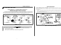
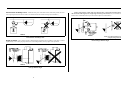
1
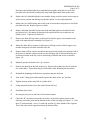
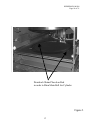
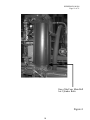
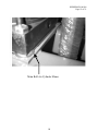
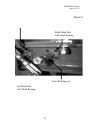
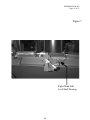
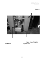
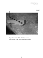
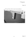
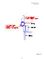
Published Manual Number/ECN: HURSPK0025/99503N
• Publishing System: TPAS
• Access date: 03/06/03
• Document ECN's: Latest Available
Kit Instruction—
KURSPK0025
KURSPK0026
PELLERIN MILNOR CORPORATION
POST OFFICE BOX 400, KENNER, LOUISIANA 70063-0400, U.S.A.
Please Read
About the Manual Identifying Information on the Cover
The front cover displays pertinent identifying information for this manual. Most important, are
the published manual number (part number) /ECN (date code). Generally, when a replacement
manual is furnished, it will have the same published manual number, but the latest available ECN.
This provides the user with the latest information applicable to his machine. Similarly all
documents comprising the manual will be the latest available as of the date the manual was
printed, even though older ECN dates for those documents may be listed in the table of
contents.
When communicating with the Milnor factory regarding this manual, please also provide the
other identifying information shown on the cover, including the publishing system, access date,
and whether the document ECN’s are the latest available or exact.
References to Yellow Troubleshooting Pages
This manual may contain references to “yellow pages.” Although the pages containing
troubleshooting procedures are no longer printed on yellow paper, troubleshooting instructions, if
any, will be contained in the easily located “Troubleshooting” chapter or section. See the table of
contents.
Trademarks of Pellerin Milnor Corporation
The following, some of which may be used in this manual, are trademarks of Pellerin Milnor
Corporation:
Ampsaver®
Autolint®
Auto-Purge®
Autovac
CBW®
Dye-Extractor®
Dyextractor®
E-P Express®
E-P OneTouch®
E-P Plus®
Gear Guardian®
Hands-Off®
Hydro-Cushion®
Mildata®
Milnet®
Milnor®
Miltrac
Miltron
Comments and Suggestions
Help us to improve this manual by sending your comments to:
Pellerin Milnor Corporation
Attn: Technical Publications
P. O. Box 400
Kenner, LA 70063-0400
Fax: (504) 469-1849
Staph-Guard®
System 4®
System 7®
Totaltrol®
MSSM0116AE/8809BV
B
SETTING LIMIT SWITCHES
È
Travel of Rotary Lever or Plunger—Set switch and target so that after the switch contacts close (as deË
Limit Switches—Including Microswitches—
Ê
Will Be Damaged If Over-actuated!
Any limit switch will be damaged if it bottoms out forcefully. This can bend the rotary shaft or damage
internal components and may cause the switch to stick in one position either permanently or intermittently. Be
aware that an intermittently sticking switch can be mistaken for a malfunctioning microprocessor!
FIGURE 1a
Rotary Lever Switch
B
Setting Switches
Ê
FIGURE 1b
Plunger Switch
FIGURE 1c
180° Roller
Plunger
FIGURE 1d
90° Roller Plunger
Switch
ÎFIGURE 1 (MSSM0116AE)
ÎLimit Switch Types
B
Limit switches must function properly to ensure the safe operation of the machine.
☞ Inspect switches regularly.
☞ Never operate a machine with a malfunctioning limit switch.
1
termined by an ohmmeter), the lever or plunger will then move approximately half of its additional available travel
(see FIGURE 2).
NOTE: It is impossible to determine by feel, sound, or experience at what point the switch contacts make.
The only reliable method is to use an ohmmeter. Switches may also be bench-tested, and the plunger or
rotary shaft scribed to mark this point.
FIGURE 2a
Rotary Lever
FIGURE 2b
Plunger Switches
(Roller Plunger Switch Shown)
ÎFIGURE 2 (MSSM0116AE)
ÎWhere Lever or Plunger Should Stop
MSSM0116AE/8809BV (1 of 2)
B
SETTING LIMIT SWITCHES
È
Travel of Rotary Lever or Plunger—Set switch and target so that after the switch contacts close (as deË
Limit Switches—Including Microswitches—
Ê
Will Be Damaged If Over-actuated!
Any limit switch will be damaged if it bottoms out forcefully. This can bend the rotary shaft or damage
internal components and may cause the switch to stick in one position either permanently or intermittently. Be
aware that an intermittently sticking switch can be mistaken for a malfunctioning microprocessor!
FIGURE 1a
Rotary Lever Switch
FIGURE 1b
Plunger Switch
B
Setting Switches
Ê
FIGURE 1c
180° Roller
Plunger
FIGURE 1d
90° Roller Plunger
Switch
ÎFIGURE 1 (MSSM0116AE)
ÎLimit Switch Types
termined by an ohmmeter), the lever or plunger will then move approximately half of its additional available travel
(see FIGURE 2).
NOTE: It is impossible to determine by feel, sound, or experience at what point the switch contacts make.
The only reliable method is to use an ohmmeter. Switches may also be bench-tested, and the plunger or
rotary shaft scribed to mark this point.
FIGURE 2a
Rotary Lever
FIGURE 2b
Plunger Switches
(Roller Plunger Switch Shown)
ÎFIGURE 2 (MSSM0116AE)
ÎWhere Lever or Plunger Should Stop
B
Limit switches must function properly to ensure the safe operation of the machine.
☞ Inspect switches regularly.
☞ Never operate a machine with a malfunctioning limit switch.
2
Free Position of Rotary Lever—Attach the rotary lever to the shaft so that, in the free position, the lever
Ë
is at a right angle to the direction of relative movement between the switch and target (see FIGURE 3).
RIGHT!
With a roller plunger switch, make sure that the roller rotates in the direction that will accommodate
the movement of the target (not at a right angle to the target movement). Also, be sure that a replacement switch
has the roller oriented the same way as the switch it replaces (see FIGURE 5).
RIGHT!
Î IGURE 3 (MSSM0116AE)
F
ÎFree Position of Rotary Lever
Angle of Switch—Set a plunger switch so that the target and plunger move parallel to each other. It will be
Ë
approximately correct when properly installed on its mounting bracket, but may require fine adjustment.
RIGHT!
ÎFIGURE 4 (MSSM0116AE)
ÎPlunger Switch Angle
3
Roller can’t absorb sideways movement
of target (wrong switch used).
ÎFIGURE 5 (MSSM0116AE)
ÎRoller Plunger Switch Angle
Free Position of Rotary Lever—Attach the rotary lever to the shaft so that, in the free position, the lever
Ë
is at a right angle to the direction of relative movement between the switch and target (see FIGURE 3).
RIGHT!
With a roller plunger switch, make sure that the roller rotates in the direction that will accommodate
the movement of the target (not at a right angle to the target movement). Also, be sure that a replacement switch
has the roller oriented the same way as the switch it replaces (see FIGURE 5).
RIGHT!
Î IGURE 3 (MSSM0116AE)
F
ÎFree Position of Rotary Lever
Angle of Switch—Set a plunger switch so that the target and plunger move parallel to each other. It will be
Ë
approximately correct when properly installed on its mounting bracket, but may require fine adjustment.
Roller can’t absorb sideways movement
of target (wrong switch used).
ÎFIGURE 5 (MSSM0116AE)
ÎRoller Plunger Switch Angle
RIGHT!
ÎFIGURE 4 (MSSM0116AE)
ÎPlunger Switch Angle
4
MSOP0922AE/9805AV
PRESS SAFETY FOR INSTALLATION AND SERVICE
È
Ê eneral Safety Requirements
G
(specific warnings, next page and throughout manual)
Incorrect installation, neglected preventive maintenance, abuse, and/or improper repairs or changes to
the machine can cause unsafe operation and personal injuries, such as multiple fractures, amputations, or
death. The owner or his selected representative (owner/user) is responsible for understanding and ensuring
the proper operation and maintenance of the machine. The owner/user must familiarize himself with the
contents of all machine instruction manuals. The owner/user should direct any questions about these instructions to a Milnor® dealer or the Milnor® Service department. Most regulatory authorities (including OSHA
in the USA) hold the owner/user ultimately responsible for maintaining a safe working environment. Therefore, the owner/user must do the following:
•
•
•
•
recognize all foreseeable safety hazards within his facility and take actions to protect his personnel,
equipment, and facility
require that personnel are familiar with all functional and safety aspects of the machine
ensure safety devices installed on the machine are in place and properly maintained
ensure all machine parts and assemblies are properly maintained.
Laundry Facility—Provide a supporting floor that is strong and rigid enough to support--with a reaË
sonable safety factor and without undue or objectionable deflection--the weight of the fully loaded machine
and the forces transmitted by it during operation. (For washer-extractors, see “ABOUT THE FORCES
TRANSMITTED BY MILNOR® WASHER-EXTRACTORS.”) Provide sufficient clearance for machine
movement. Provide any safety guards, fences, restraints, devices, and verbal and/or posted restrictions necessary to prevent personnel, machines, or other moving machinery from accessing the machine or its path.
Provide adequate ventilation to carry away heat and vapors. Ensure service connections to installed machines meet local and national safety standards, especially regarding the electrical disconnect (see the National Electric Code). Prominently post safety information, including signs showing the source of electrical
disconnect.
Personnel—Inform personnel about hazard avoidance and the importance of care and common sense.
Ë
Provide personnel with the safety and operating instructions that apply to them. Verify that personnel use
proper safety and operating procedures. Verify that that personnel understand and abide by point-of-hazard
tags on the machine and procedure-specific precautions in the instruction manuals.
Safety Devices—Ensure that no one eliminates or disables any safety device on the machine or in the
Ë
facility. Do not allow machine to be used with any missing guard or cover. Service any failing or malfunctioning device before operating the machine.
Maintenance—Ensure the machine is inspected and serviced in accordance with the norms of good
Ë
practice and with the preventive maintenance schedule. Replace belts, pulleys, brake shoes/disks, clutch
plates/tires, rollers, seals, alignment guides, etc. before they are severely worn. Immediately investigate any
evidence of impending failure and make needed repairs (e.g., cylinder, shell, or frame cracks; drive components such as motors, gear boxes, bearings, etc., whining, grinding, smoking, or becoming abnormally hot;
bending or cracking of cylinder, shell, frame, etc.; leaking seals, hoses, valves, etc.) Do not permit service
or maintenance by unqualified personnel.
Danger From a Descending Press Main Bell
Ê
CRUSH HAZARD—Descending main bell will crush anyone under it. Bell
can descend even with power off.
☞ NEVER crawl or reach under the press main bell.
☞ Lock OFF and tag out power and secure factory-supplied safety supports in place
before crawling or reaching under the bell to perform service or maintenance.
☞ ALWAYS ensure all personnel are clear of the press and receiving conveyor before returning power to either machine for service or maintenance.
Danger From Exposed Electrical Components
Ê
COLLISION, CRUSHING, AND PINCH HAZARDS—Serious bodily injury or
death can result to personnel in proximity to machinery/systems that
traverse, elevate, extend, pivot, and/or tilt. The following mandatory minimum safety requirements must be installed with the machinery system:
☞ Safety fence inclosing machine movement areas,
SHOCK HAZARD—Contact with high voltage inside electrical boxes or
from other exposed electrical components can kill or seriously injure
you.
☞ Lockable electric interlocks on all gates, properly interfaced as shown on machine schematics, to disable machine movement when any gate is opened,
☞ Lock OFF and tag out power at wall disconnect before opening any
electrical control boxes.
☞ Signs to alert personnel to these hazards, placed prominently around the fenced
area.
☞ ALWAYS employ the services of a licensed, qualified electrician when troubleshooting the electrical system.
☞ Local codes may require additional precautions.
5
MSOP0922AE/9805AV (1 of 2)
PRESS SAFETY FOR INSTALLATION AND SERVICE
È
Ê eneral Safety Requirements
G
(specific warnings, next page and throughout manual)
Incorrect installation, neglected preventive maintenance, abuse, and/or improper repairs or changes to
the machine can cause unsafe operation and personal injuries, such as multiple fractures, amputations, or
death. The owner or his selected representative (owner/user) is responsible for understanding and ensuring
the proper operation and maintenance of the machine. The owner/user must familiarize himself with the
contents of all machine instruction manuals. The owner/user should direct any questions about these instructions to a Milnor® dealer or the Milnor® Service department. Most regulatory authorities (including OSHA
in the USA) hold the owner/user ultimately responsible for maintaining a safe working environment. Therefore, the owner/user must do the following:
•
•
•
•
recognize all foreseeable safety hazards within his facility and take actions to protect his personnel,
equipment, and facility
require that personnel are familiar with all functional and safety aspects of the machine
ensure safety devices installed on the machine are in place and properly maintained
ensure all machine parts and assemblies are properly maintained.
Laundry Facility—Provide a supporting floor that is strong and rigid enough to support--with a reaË
sonable safety factor and without undue or objectionable deflection--the weight of the fully loaded machine
and the forces transmitted by it during operation. (For washer-extractors, see “ABOUT THE FORCES
TRANSMITTED BY MILNOR® WASHER-EXTRACTORS.”) Provide sufficient clearance for machine
movement. Provide any safety guards, fences, restraints, devices, and verbal and/or posted restrictions necessary to prevent personnel, machines, or other moving machinery from accessing the machine or its path.
Provide adequate ventilation to carry away heat and vapors. Ensure service connections to installed machines meet local and national safety standards, especially regarding the electrical disconnect (see the National Electric Code). Prominently post safety information, including signs showing the source of electrical
disconnect.
Personnel—Inform personnel about hazard avoidance and the importance of care and common sense.
Ë
Provide personnel with the safety and operating instructions that apply to them. Verify that personnel use
proper safety and operating procedures. Verify that that personnel understand and abide by point-of-hazard
tags on the machine and procedure-specific precautions in the instruction manuals.
Safety Devices—Ensure that no one eliminates or disables any safety device on the machine or in the
Ë
facility. Do not allow machine to be used with any missing guard or cover. Service any failing or malfunctioning device before operating the machine.
Maintenance—Ensure the machine is inspected and serviced in accordance with the norms of good
Ë
practice and with the preventive maintenance schedule. Replace belts, pulleys, brake shoes/disks, clutch
plates/tires, rollers, seals, alignment guides, etc. before they are severely worn. Immediately investigate any
evidence of impending failure and make needed repairs (e.g., cylinder, shell, or frame cracks; drive components such as motors, gear boxes, bearings, etc., whining, grinding, smoking, or becoming abnormally hot;
bending or cracking of cylinder, shell, frame, etc.; leaking seals, hoses, valves, etc.) Do not permit service
or maintenance by unqualified personnel.
Danger From a Descending Press Main Bell
Ê
CRUSH HAZARD—Descending main bell will crush anyone under it. Bell
can descend even with power off.
☞ NEVER crawl or reach under the press main bell.
☞ Lock OFF and tag out power and secure factory-supplied safety supports in place
before crawling or reaching under the bell to perform service or maintenance.
☞ ALWAYS ensure all personnel are clear of the press and receiving conveyor before returning power to either machine for service or maintenance.
Danger From Exposed Electrical Components
Ê
COLLISION, CRUSHING, AND PINCH HAZARDS—Serious bodily injury or
death can result to personnel in proximity to machinery/systems that
traverse, elevate, extend, pivot, and/or tilt. The following mandatory minimum safety requirements must be installed with the machinery system:
☞ Safety fence inclosing machine movement areas,
SHOCK HAZARD—Contact with high voltage inside electrical boxes or
from other exposed electrical components can kill or seriously injure
you.
☞ Lockable electric interlocks on all gates, properly interfaced as shown on machine schematics, to disable machine movement when any gate is opened,
☞ Lock OFF and tag out power at wall disconnect before opening any
electrical control boxes.
☞ Signs to alert personnel to these hazards, placed prominently around the fenced
area.
☞ ALWAYS employ the services of a licensed, qualified electrician when troubleshooting the electrical system.
☞ Local codes may require additional precautions.
6
7
☞ ALWAYS ensure all personnel are clear of press and receiving conveyor before
returning power to either machine.
☞ DO NOT stand or walk on the receiving conveyor or belt at the press discharge
end when performing service or maintenance.
☞ Lock OFF and tag out power at wall disconnect before servicing the receiving
conveyor or press.
FALL HAZARD—The receiving conveyor starts without warning. Standing or walking on the conveyor may cause you to fall or be entangled in
or struck by moving system devices.
Danger From Moving Conveyor
Ê
☞ DO NOT climb on press unless press power is locked OFF and tagged out.
☞ ALWAYS ensure all personnel are clear of the press and the receiving conveyor
and all press side doors are closed and guards are in place before returning
power to either machine.
☞ NEVER touch or reach into assemblies in or above press frame unless
power is locked OFF and tagged out, and then only for maintenance.
CRUSH HAZARD—Devices in and above the press move without warning
and can entangle, crush, or sever limbs on contact.
Danger From an Operating Press
Ê
HURSPK0026/00186
Page 1 of 21
INSTRUCTIONS FOR 50 KILO AND 60 KILO PRESS SHIM RETRO-FIT
These instructions are for adding shims under the main bell air cylinder on 50 kilo and 60 kilo
presses. Before beginning to add shims below the air cylinder, it is necessary to familiarize
yourself with all safety precautions in the equipment's manuals; please observe all safety
precautions. It is also imperative that these instructions, including the attached drawing
are read and understood before beginning the retrofit. While working on any equipment,
tag and lockout the power. Also, inventory the parts received with the kit.
Please read through these instructions thoroughly before beginning implementation of the
shims to the main bell air cylinder.
Some of the tools, which will be needed to perform this product enhancement, are as follows:
SAE size wrenches, Allen wrenches, lineup pin, and assorted hand tools.
MILNOR will provide installation labor costs for placing shims and replacing the up-lock
assembly. We anticipate this labor not to exceed 10 man-hours per machine, i.e. one man at ten
hours or two men at five hours each for a total of ten hours per retrofit.
INSTRUCTIONS:
We recommend that a qualified maintenance employee or dealer personnel perform this
product enhancement.
1.
Using a permanent marker, trace the outline of the main bell air cylinder onto the upper
cross-member. This will give an outline for centering the main bell air cylinder onto the
upper cross-member at the completion of the project (See Figure 1).
2.
Operate the dome from the up position to the down position. As the dome makes contact
with the bed, check to see if the dome meets the bed flush or side touches the bed first
(the dome is cocked in relation to the bed).
3.
Remove the diaphragm from the dome (See Milnor Membrane Press SERVICE Manual).
4.
Manually operate the dome to the down position.
5.
Loosen the bolts on the coupling, which joins the air cylinder shaft to the top of the dome
downlock hub assembly (See Figure 2).
6.
Remove this coupling from the shaft.
7.
Place the 12 bolt-hole coupler shim on top of the dome downlock hub assembly (with
bolt holes properly aligned).
8
HURSPK0026/00186
Page 2 of 21
8.
Replace the coupling onto the shaft on top of the 12 bolt-hole coupler shim.
9.
Evenly torque the bolts of the coupling to 25 foot pounds (33.9 Newton meters) (using
the cross torque method starting with the four bolts at the split of the coupling).
10.
Manually operate the dome to the up position.
11.
Loosen the bolts which holds the main bell air cylinder to the upper cross-member (see
Figure 1). This should be done with the dome in the "up" position. DO NOT
completely remove bolts from air cylinder base. The bolts should be loosened so that
there is at least a 0.5 inch (13 millimeter) gap between the nut and the upper crossmember frame.
12.
Take one 0.046" (1.1684mm) downlock shim (the thinnest shim in the kit) and one
0.056" (1.4224mm) downlock shim (the second to thinnest shim in the kit) and stack
them together. Make two sets of downlock shim stacks
13.
Place one set of the downlock shim stacks on the right-hand side of the bed so that the
dome will sit on the shims instead of the bed when lowered. Place the second set of
shims on the left-hand side of the bed (See Figure 3).
14.
The dome should then be manually operated to the "down" position so that it is resting on
the shims on the bed (this will give a 0.102" (2.5908mm) clearance between the bed and
the dome).
15.
When the dome is in the down position, there should be a gap between the bottom of the
air cylinder and the upper cross-member - if a gap exists, the gap should be approximately
1/4" (6.35mm).
16.
Make sure that all of the nuts and bolts from the main bell air cylinder and upper cross
member are loosened enough so that they are not holding the air cylinder down.
17.
Measure the gap between the upper cross member and the main bell air cylinder on all
four corners of the air cylinder.
18.
Determine which corner of the air cylinder has the largest gap between it and the upper
cross member.
19.
With the dome in the “down” position, tag and lockout the power.
20.
Locate the corner of the air cylinder, which has the largest gap between it and the upper
cross member. Remove this nut and bolt from the main bell air cylinder base where it is
connected to the upper cross-member (See Figure 4).
9
HURSPK0026/00186
Page 3 of 21
21.
Slide as many large shims in the gap between the base and cross-member as possible. If a
gap remains between the large shims and the main bell air cylinder, slide as many smaller
shims between the large shim and the base of the air cylinder to fill the remaining gap.
The last shim may be a tight fit between the other shims and the base of the air cylinder,
so that you may have to tap the shim into place.
22.
Remove the stack of shims from underneath the air cylinder. If step (7) of these
instructions was implemented then add two more of the thin shims (0.025" / 0.635mm) to
the current stack of shims. Use this stack of shims to make three more identical shim
stacks.
23.
Untag the machine and raise the dome to the “up” position.
24.
Add one additional 0.056" (1.4224mm) shim to each of the two sets of shims on the press
bed (Refer to Step 12).
25.
Lower the dome to the “down” position.
26.
With the dome in the “down” position, tag and lockout the power.
27.
Remove one of the four nuts and bolts from the main bell air cylinder base where it is
connected to the upper cross-member (See Figure 4).
28.
Slide one of the four air cylinder shim stacks from Step (22) in between the air cylinder
and the upper cross member so that the shim stack lines up with the bolt hole. After the
shim stack is in place, place a new longer bolt (included in the kit) through the upper
cross member hole, the shims, and the air cylinder. Put the lock washer onto the bolt.
Hand tighten the nut onto the bolt (See Figure 5).
29.
Repeat steps (27) and (28) for the remaining three bolts of the air cylinder base.
30.
Visually check if the uplock brackets are closing fully. If the brackets cannot fully close,
then proceed to step (22). If the brackets can close fully then proceed to step (41).
31.
When facing the main bell air cylinder from the discharge side of the press, remove the
pin from the uplock bracket clevis that is connected to the right-hand uplock assembly
bracket. (See Figure 6)
32.
Loosen the “bracket clamping bolt” on the right-hand uplock assembly bracket. Do not
remove the contact switches from the bracket. Next remove the right-hand lock shaft nut
and remove the right-hand bracket (See Figure 6).
33.
Remove the spacers on the right-hand lock shaft between the up lock shaft bolt and the
upper lock shaft bearing. Note the order of the spacers, they need to be replaced in
the same order that they were removed (See Figure 7). Remove the right-hand up lock
10
HURSPK0026/00186
Page 4 of 21
34.
shaft bearing from the upper cross-member (See Figure 8).
Loosen the two bolts that join the shaft-lock to the right-hand uplock jaw. Note the
position of the uplock so that it can be reinstalled in the same position. Mark the spacers
that are between the two bearings so that they may be reinstalled in the same place from
which they were removed. Carefully remove the lock shaft, through the hole created by
the removed bearing, while holding the uplock and the spacers on both sides of the
uplock (See Figure 9).
35.
Remove the bolts holding the uplock and shaft-lock together (See Figure 9). Discard the
old uplock and replace with the new shorter uplock provided in the kit. File off the paint
on the inside of the square hole on the sides of the new uplock jaw (See Figure 10).
Reconnect the uplock and shaft-lock together using the new lock-nuts provided in the kit
and the existing bolts (only hand tighten these bolts at this time).
36.
Replace the right-hand uplock shaft through the cross-member, being careful to put the
correct spacers in the correct position and making sure that the uplock is in its original
centered position.
37.
Replace the right-hand uplock shaft bearing and re-bolt to the cross-member using the
new lock-bolts provided in the kit. Replace spacers on shaft between the bearing and
lock-nut.
38.
Replace right-hand assembly bracket onto shaft and hand tighten right-hand uplock shaft
lock bolt (provided in kit). Reconnect the bracket to the uplock bracket clevis. Tighten
lock shaft bolt.
39.
Remove the pins from the clevis connected to the left-hand assembly bracket (air cylinder
clevis and uplock bracket clevis) (See Figure 6).
40.
Loosen the “bracket clamping bolt” on the left-hand uplock assembly bracket. Next
remove the left-hand lock shaft nut and remove the left-hand bracket (See Figure 6).
41.
Remove the spacers on the left-hand lock shaft between the upper lock shaft nut and the
upper lock shaft bearing. Keep these spacers separate, the spacers need to be
replaced in the same order that they were removed (See Figure 7). Remove the lefthand upper lock shaft bearing from the upper cross-member (See Figure 7).
42.
Loosen the two bolts that join the shaft-lock to the left-hand uplock jaw. Note the
position of the uplock so that it can be reinstalled in the same position. Carefully remove
the left-hand lock shaft, from the removed bearing side, while holding the left-hand
uplock jaw and the spacers on both sides of the uplock jaw (See Figure 9).
43.
Remove the bolts holding the left-hand uplock jaw and shaft-lock together (See Figure 9).
Discard the old uplock and replace with the new uplock provided in the kit. File off the
paint on the inside of the square hole on the sides of the uplock (See Figure 10).
11
HURSPK0026/00186
Page 5 of 21
Reconnect the left-hand uplock jaw and shaft-lock together using the new lock-nuts
provided in the kit and the existing bolts (only hand tighten these bolts at this time).
44.
Replace the lock shaft through the cross-member, being careful to put the correct spacers
in the correct position and making sure that the uplock is in its original position.
45.
Replace the lock shaft bearing and re-bolt to the cross-member using the new lock-bolts
provided in the kit. Replace spacers on shaft.
46.
Replace left-hand assembly bracket onto shaft and hand tighten lock shaft lock bolt
(provided in kit). Reconnect the bracket to the uplock bracket clevis and to the air
cylinder clevis. Tighten lock shaft bolt.
47.
Remove the dome full-up contact switch bracket from the upper cross-member to the
right of the uplock bracket assembly (See Figure 11).
48.
Rotate the dome full-up contact switch bracket 180 degrees and re-bolt to upper crossmember using new lock bolts included in the kit.
49.
Remove dome full-up contact switch from the bracket and re-bolt to the opposite side of
the bracket so that the contact switch is on the discharge side of the bracket using new
lock bolts included in the kit (Correct Positioning of bracket and switch is shown in
Figure 12).
50.
Manually operate the dome to the “up” position.
51.
Remove the shims from the bed of the press. Replace these shims into the kit with the
rest of the shims. These shims may be needed later when shimming the downlocks.
52.
Reinstall the diaphragm with the new expansion ring into the dome.
53.
Turn on the 2-Stage press and manually operate the dome to the “up” position.
54.
Tighten the nuts on the main bell air cylinder bolts.
55.
Using manual functions, lower the main bell onto the bed.
56.
Extend the down locks.
57.
De-energize press power and lock off at main disconnect.
58.
Check the “B” clearance between the top surface of the lock segment closest to the
discharge end of the press and the bottom surface of the lock ring (see Figure 13). Take
three (3) measurements - one (1) at each end, and one (1) in the middle of the segment.
This is the most critical segment and must be shimmed first.
12
HURSPK0026/00186
Page 6 of 21
59.
Repeat step (49) for the other lock segments. Record all measurements - they will be
used in determining the thickness of the required shims. (Even if most of the
measurements are within the specified range, each lock segment will still have to be
shimmed. This is because any changes to the shimming of the lock ring above any one
segment will affect the “B” clearances of the other segments.)
60.
Re-energize the press. Using manual functions, retract the downlocks. When the
downlocks are fully retracted, de-energize the press and lock power off at main
disconnect.
61.
Loosen all nine (9) bolts that secure the lock ring to the main bell (twelve (12) bolts for
the 60 Kg press), but do not remove. Loosen enough so that there is approximately 2" (13
mm) of gap between the ring and the main bell (See Figure 14).
62.
Remove the three (3) bolts from the lock ring, which are common to the shim set closest
to the discharge end. Remove the shim set that was previously installed and retain for
future use (See Figure 14).
63.
Measure the thickness of the shim set that was just removed. Refer back to the
measurements taken in steps 49 and 50.
64.
Calculate the required shim set thickness by determining (using the original clearance
measurements) how much must be added (or subtracted) from the original shim set
thickness to bring the “B” clearance into the specified range. (If shims were added
between the main bell air cylinder and the upper cross member, then you will need to
remove some thickness on the downlock ring shims.)
EXAMPLE
After replacing a main bell air cylinder, 0.015" (0.38 mm) of extra shimming had to be added
between the cylinder and the machine upper cross member. The readings taken on the down lock
closest to the discharge end of the press are 0.002" (0.05 mm), 0.007" (0.18 mm), and 0.005"
(0.13 mm). In order to bring the “B” measurement back into the proper range, it is necessary in
this case to subtract between 0.003" (0.08 mm) and 0.023" (0.58 mm) of shim.
Thus, we can safely subtract 0.015" from the shim thickness, and this should result in new “B”
clearances of 0.018" (0.46 mm), 0.022" (0.56 mm), and 0.012" (0.30 mm).
65.
Install the new shim segment between the lock ring and the dome and reinstall the three
bolts previously removed but don’t tighten them. All bolts will be tightened when all
shim segments are installed (See Figure 14).
66.
Repeat the previous operations for the remaining shim segments. When calculating shim
thickness for the other lock segments, it is important to make sure that the calculated
13
HURSPK0026/00186
Page 7 of 21
clearances (that is, the clearances which should result when the new shim thickness is
added or subtracted from the readings obtained earlier) are within the permissible range.
67.
When all shim segments have been installed, tighten all bolts (nine for the 50 Kg press,
twelve for the 60 Kg press).
68.
Energize the press. Using manual functions, cycle the downlocks from the retracted
position to the extended position and back a few times.
69.
Extend the downlocks, de-energize the press, and lock power off at the main disconnect.
70.
Check and verify the “B” clearances (see Figure 13) are within the permissible range. If
necessary, readjust the shims as directed in previous steps. If there is a major variation
which results in some or all of the measurements being out of the permissible range, and
the proper clearances cannot be achieved through shimming, contact the MILNOR
service department or your MILNOR dealer.
71.
Energize the press. Manually operate the press to make sure that everything is
functioning properly.
Please follow the attached MILNOR directions on how to adjust the contact switches for
the uplocks and dome full-up.
If you have any questions regarding the method of handling of this issue, please contact
Technical Support at 504-467-9591, ext.276.
14
HURSPK0026/00186
Page 8 of 21
Main Bell Air
Cylinder Bolts
Trace Outline of Main Bell Air Cylinder Base on Upper Cross Member
Figure 1
15
HURSPK0026/00186
Page 9 of 21
Torque
To
25 ft-lb
(33.9 Nm)
Main Dome Coupling
Figure 2
16
HURSPK0026/00186
Page 10 of 21
Downlock Shims Placed on Bed
in order to Shim Main Bell Air Cylinder
Figure 3
17
HURSPK0026/00186
Page 11 of 21
One of the Four Main Bell
Air Cylinder Bolts
Figure 4
18
HURSPK0026/00186
Page 12 of 21
Main Bell Air Cylinder Shims
19
HURSPK0026/00186
Page 13 of 21
Figure 5
Air
Cylinder
Clevis
Uplock
Bracket
Clevis
Bracket
Clamping
Bolt
Left-Hand Uplock
Assembly Bracket
Right-Hand Uplock
Uplock Shaft
Assembly Bracket
Nut and Bolt
20
HURSPK0026/00186
Page 14 of 21
Figure 6
Right-Hand Side
Lock Shaft Bearing
Lock Shaft Spacers
Left-Hand Side
Lock Shaft Bearing
21
HURSPK0026/00186
Page 15 of 21
Figure 7
Right-Hand Side
Lock Shaft Bearing
22
HURSPK0026/00186
Page 16 of 21
Figure 8
Upper Cross-Member
Uplock Jaw
Shaft Lock
23
HURSPK0026/00186
Page 17 of 21
Figure 9
Square Holes in the Side of the Uplock Jaw
(File Paint off of the Inside surface of the Holes)
24
HURSPK0026/00186
Page 18 of 21
Figure 10
Old Setup of Dome Full-Up Contact Switch and Bracket
25
Figure 11
HURSPK0026/00186
Page 19 of 21
New Positioning of Dome Full-Up Contact Switch and Bracket
Dome Full-Up Contact Switch Bracket
Dome Full-Up Contact Switch
Figure 12
26
HURSPK0026/00186
Page 20 of 21
Figure 13
27
HURSPK0026/00186
Page 21 of 21
Location of Downlock Shims
Lock Ring Bolts
Figure 14
28


![English-T series-NOVA-User manual-F [兼容模式]](http://vs1.manualzilla.com/store/data/005791006_1-acba31ea472695c25db426bea2198a0f-150x150.png)