1
Published Manual Number: MTCJXR01
• Specified Date: 20070531
• As-of Date: 20070531
• Access Date: 20070531
• Custom: n/a
• Applicability: CJX
• Language Code: ENG01, Purpose: publication, Format: 1colA
Technical Reference—
Operating,
Programming, and
Troubleshooting the E-P
Express® Controller
PELLERIN MILNOR CORPORATION
POST OFFICE BOX 400, KENNER, LOUISIANA 70063 - 0400, U.S.A.
Applicable Milnor® products by model number:
30010G5X
30015G5X
30015T5X
30022T5X
MWR18X4-
Preface
Preface
BICJXK01 (Published) Book specs- Dates: 20070531 / 20070531 / 20070531 Lang: ENG01 Applic: CJX
i. About this Manual
i. 1.
Scope
This manual provides commissioning, programming, operating, and troubleshooting instructions
for Milnor® washer-extractors using the E-P Express® microprocessor control system. See the
installation manual for information on machine installation procedures and mechanical
requirements. See the service manual for preventive maintenance, service procedures, and
mechanical parts identification. See the schematic manual for electrical parts identification and
electrical troubleshooting instructions.
i. 2.
Best Available Information [Document BIUUUD17]
This manual contains the most accurate and complete information available when Milnor shipped
your machine/software. Products are occasionally released with the best available documentation,
even though the device identification (model numbers, etc.) on the documentation does not
explicitly include the delivered model. In such cases, use the documentation provided.
Although unlikely, incorrect manuals may have shipped with your machine. If you believe you
received the wrong manuals, or if you need specific information about any aspect of your machine
not addressed in the provided documentation, contact the Milnor Customer Service group.
i. 3.
The Normal Display at Start-up
The start-up display sequence for E-P Express® machines is described in document BICJHO01,
entitled “Running a Formula.” Use the table of contents for this manual to locate this document.
i. 4.
How to Identify this Manual and its Included Documents [Document
BIUUUD13]
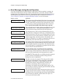
A complete identification of this manual or any document in this manual must include all
specifications shown on the front cover, as defined below:
Published manual number—Primary identification number for the manual or any variation of it.
Specified date—The approximate date of introduction of the product or product change this
manual covers.
As-of date—When a manual for an old product is generated, any new information about the old
product developed up to this date will be included in the manual.
Access date—The date the manual was generated (assembled and formatted).
Applicability—Code(s) that represent a group of machines this manual applies to and/or actual
model numbers of applicable machines. The complete list of applicable models is provided
inside the front cover. If “not used” appears here, this is not a product manual, but has another
purpose such as to provide administrative procedures.
PELLERIN MILNOR CORPORATION
Preface
Language Code—A code representing the specific language and dialect of this manual. “Eng01”
identifies the language/dialect of the manual as United States English.
When referring to any document used in this manual (as identified by an eight-character document
number such as BIUUUD13 at the start of the document), a complete identification of the
document must include all specifications shown on the front cover, except substituting the
document number for the published manual number.
i. 5.
i. 5.1.
Trademarks [Document BIUUUD14]
Trademarks of Pellerin Milnor Corporation—The following terms, some of which may
be used in this publication, are trademarks of Pellerin Milnor Corporation:
Table 1: Trademarks
i. 5.2.
CBW®
E-P OneTouch®
Mentor®
Milnet®
Staph-Guard®
E-P Express®
E-P Plus®
Gear Guardian®
Mildata®
Milnor®
MultiTrac™
Visionex™
Trademarks of Other Companies—The following terms, some of which may be used in
this publication, are trademarks of their respective companies:
Table 2: Trademarks
Acronis®
IBM®
Microsoft Office
XP®
Microsoft Access®
Siemens®
Atlas 2000®
Microsoft Windows
2000®
Microsoft Windows
NT®
Microsoft Windows
XP®
Seagate Crystal
Reports®
Yaskawa®
— End of BICJXK01 —
PELLERIN MILNOR CORPORATION
Table of Contents
Table of Contents
Sections
Figures, Tables, and Supplements
Preface
i. About this Manual (Document BICJXK01)
i.1. Scope
i.2. Best Available Information (Document BIUUUD17)
i.3. The Normal Display at Start-up
i.4. How to Identify this Manual and its Included Documents
(Document BIUUUD13)
i.5. Trademarks (Document BIUUUD14)
i.5.1. Trademarks of Pellerin Milnor Corporation
i.5.2. Trademarks of Other Companies
Table 1: Trademarks
Table 2: Trademarks
Table of Contents
Chapter 1. Commissioning
1.1. Important Owner/User Information (Document BIRHUK01)
1.1.1. Ensure Safety of All Laundry Personnel
1.1.2. Customize Data
1.1.2.1. When to Customize Data
1.1.2.2. What Customizing Requires
1.1.2.3. Data Accessibility
1.1.2.4. If Data Becomes Corrupted
Table 3: Data Use and Alteration
1.2. About the Forces Transmitted by Washer-extractors
(Document BIWUUI02)
1.2.1. Foundation Considerations
1.2.2. How Strong and Rigid?
Figure 1: How Rotating Forces Act on the
Foundation
Figure 2: How Rotating Forces Act on the
Foundation
1.3. Important Instructions for Pumped Chemical Inlets
(Document BIWUUI01)
1.3.1. How Pumped Chemical Systems can Internally Damage the Supplement 1: Preventing Dribbling by
Washer-extractor
Purging Chemical Lines
1.3.2. Locating Chemical System Components to Reduce the Risk Figure 3: Proper Routing of Chemical
of Internal Damage
Tubing
1.3.3. Preventing Leaks Which Can Injure Personnel and Cause
Figure 4: Rear-mounted Water and Liquid
External Damage
Supply Injector
1.4. Electrical Connections for Liquid Chemical Systems
(Document BICEUI01)
Supplement 2: Maximizing Chemical
Injection Precision
PELLERIN MILNOR CORPORATION
Table of Contents
Sections
Figures, Tables, and Supplements
1.4.1. Pump Signal Connections
Table 4: Chemical Injection Signals
Figure 5: Pump Signal Connections
Figure 6: Timer Stop Connections
1.4.2. Timer Stop Connections
Chapter 2. Programming
2.1. Controls on E-P Express® Washer-extractors
(Document
Figure 7: E-P Express Control Panel
BICJHC01)
2.1.1. Control Functions During Normal Operation
2.1.2. Control Functions During Manual Operation
2.1.3. Control Functions During Programming
2.2. Selecting an Industry Formula Set
(Document BICJHC02)
Figure 8: Location of DIP Switches
Table 5: DIP Switch Settings for Industry
Configurations
2.3. Programming the E-P Express® Control (Document BICJXP01)
2.3.1. How to Avoid Data Loss
2.3.2. How to Return to Run Mode
2.3.3. How to Add or Change a Formula
2.3.3.1. Quick Reference for E-P Express Programming
2.3.3.2. Moving through the Operations and Decisions
2.3.3.3. How to Create a New Formula
2.3.3.4. How to Delete a Formula
2.3.3.5. How to Change a Formula
2.3.3.5.1. How to Insert or Delete a Step in an Existing
Formula
2.3.3.5.2. Inserting a Step
2.3.3.5.3. Deleting a Step
2.3.3.5.4. How to Save Changes
2.3.3.6. The Step Decisions
2.3.3.6.1. TT = Step Type
Table 6: Summary of Step Types
2.3.3.6.2. MMQ = Step Time
2.3.3.6.3. C = Chemicals
2.3.4. How to Configure the Controller
2.3.4.1. Moving through the Configure Screens
2.3.4.2. The Configure Decisions
2.3.5. Restoring the Standard Formulas
2.3.6. Data Transfer (Option 4)
PELLERIN MILNOR CORPORATION
(Document BICJUP01)
(Document BICJUP13)
Table 7: Chemical Signals and Supplies
Supplement 3: About Chemical Injection
with the E-P Express Controller
Figure 9: Procedure for Restoring Standard
Formulas
Table 8: Controllers Capable of
Transferring Memory
Figure 10: Controls Identification on Serial
Memory Storage Device
Table of Contents
Sections
Figures, Tables, and Supplements
2.3.6.1. Establishing the Required Connections
2.3.6.2. Saving Data from the Machine to the Storage Device or
a Second Machine
2.3.6.3. Restoring Saved Data to the Machine from the Storage
Device or Another Machine
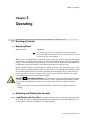
Chapter 3. Operating
3.1. Running a Formula (Document BICJHO01)
3.1.1. Applying Power
3.1.2. Selecting and Starting the Formula
3.1.2.1. Load Machine and Close Door
3.1.2.2. Selecting a Formula
3.1.3. Unloading the Machine
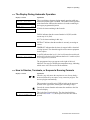
3.1.4. The Display During Automatic Operation
3.1.5. How to Shorten, Terminate, or Suspend a Running Formula
3.1.6. How to Restart after Power Loss
3.1.7. How the Flush Valve Works
3.2. Viewing and Clearing the Formula Count Accumulator
(Document BICJUD01)
Chapter 4. Testing and Troubleshooting
4.1. Error Messages (Document BICJHT01)
4.1.1. Error Messages at Power Up
4.1.2. Error Messages during Normal Operation
4.2. The E-P Express® Manual Menu (Document BICJHT03)
4.2.1. The Manual Menu
4.2.1.1. Components
4.2.1.2. How to Access the Manual Menu
4.2.1.3. How to Return to the Run Mode from the Manual Menu
4.2.2. Determining the Software Version
4.2.3. Viewing Microprocessor Inputs
Table 9: E-P Express Inputs
4.2.4. Actuating Microprocessor Outputs
Table 10: E-P Express Outputs
4.2.5. Testing and Verifying the DIP Switch Settings
Figure 11: Processor Board
Table 11: Interpretation of Test DIP Switch
Display
4.2.6. Viewing Inputs and Outputs while Machine is Operating
Chapter 5. Supplemental Information
5.1. The E-P Express® Hardware
5.1.1. Keyswitches
(Document BICJUF01)
PELLERIN MILNOR CORPORATION
Table of Contents
Sections
Figures, Tables, and Supplements
5.1.1.1. Run/Program Keyswitch
5.1.1.2. Automatic/Test Keyswitch
5.1.2. Display
5.1.3. Power Supply
5.1.4. CPU Processor Board
5.1.5. Outputs
5.1.6. Option Outputs
5.1.7. Analog to Digital Convertor
5.1.8. Temperature Probe
5.1.9. Pressure Sensor
5.2. Serial Memory Storage Device Applications
(Document
BICUDC01)
5.3. Construction of External Serial Link Cables
Figure 12: Serial Memory Storage Device
Figure 13: Rear View of Circuit Board
Table 12: DIP Switch Positions for Use
with E-P Plus and E-P Express
Machines (External Transmit Button
Required)
(Document
BICWUC01)
5.3.1. Pin Identification
5.3.2. How to Wire the Cables
5.3.2.1. Cable Specifications
5.3.2.2. Connecting Two or More Machines for
Machine-to-machine Transfer
5.3.2.3. Connecting a Machine to a Serial Memory Storage
Device
PELLERIN MILNOR CORPORATION
Figure 14: 9-Pin DIN Connector Pin
Identification (from wire entry side of
connectors)
Table 13: External Serial Link Pin
Assignments
Figure 15: Wiring Diagram for Cable to
Connect Two or More Machines
Figure 16: Wiring Diagram for Cable to
Connect a Machine to a Serial Memory
Storage Device
Chapter 1. Commissioning
Chapter 1
Commissioning
BIRHUK01 (Published) Book specs- Dates: 20070531 / 20070531 / 20070531 Lang: ENG01 Applic: CJX
1.1. Important Owner/User Information
The following two procedures must be completed before this machine is placed in service:
1. Ensure the safety of all laundry personnel.
2. Customize the data contained in the memory of the machine (configuration, formulas, and
productivity/formula accumulator data).
1.1.1.
Ensure Safety of All Laundry Personnel
Ensure that all personnel who will operate or maintain this machine read the safety manual before
permitting them to access the machine. Ensure that all user manuals are available to the appropriate
personnel and that all precautions explained in all applicable manuals are observed.
1.1.2.
Customize Data
Customizing the data includes verifying that the controller is configured for the particular
application, modifying certain wash programs if necessary for optimum productivity, and verifying
that the formula count accumulator is cleared so the formula count will be accurate.
1.1.2.1.
When to Customize Data
•
•
•
•
•
When commissioning the machine
When required by error message
After replacing the microprocessor board
After upgrading the software
After adding or removing optional equipment
1.1.2.2.
What Customizing Requires—Verify configuration. Program formulas and clear
productivity data, if applicable. See the programming and operating sections in this manual for
instructions.
1.1.2.3.
Data Accessibility—Configuration and formula data can only be altered while the keyswitch
is in the Program position (data is protected by the keyswitch). Productivity data, because it is
accumulated in the Run mode, cannot be protected by the keyswitch and is accessible to anyone.
Data is accessible to the extent described in Table 3.
PELLERIN MILNOR CORPORATION
Chapter 1. Commissioning
Table 3: Data Use and Alteration
Data Type
How Data can be Used and Altered
Configuration Data
Formula Data
Productivity Data
Data can be read and written over
Data can be read, written over (added to/changed) and cleared
Data can be read and cleared
1.1.2.4.
If Data Becomes Corrupted—If the microprocessor senses that data is unusable or
unreliable, an error message will appear—usually at power-up—possibly preventing machine
operation. The consequences and appropriate actions for each error message are explained in the
troubleshooting instructions. Follow these instructions exactly to ensure that corrupt data is
completely eliminated and replaced with valid data. Failure to do so may result in unsafe operation
or machine damage.
— End of BIRHUK01 —
BIWUUI02 (Published) Book specs- Dates: 20070531 / 20070531 / 20070531 Lang: ENG01 Applic: CJX
1.2. About the Forces Transmitted by Washer-extractors
During washing and extracting, all washer-extractors transmit both static and dynamic (cyclic)
forces to the floor, foundation, or any other supporting structure. During washing, the impact of the
goods as they drop imparts forces which are quite difficult to quantify. Size for size, both rigid and
flexibly-mounted machines transmit approximately the same forces during washing. During
extracting, rigid machines transmit forces up to 30 times greater than equivalent flexibly-mounted
models. The actual magnitude of these forces vary according to several factors:
• machine size,
• final extraction speed,
• amount, condition, and type of goods being processed,
• the liquor level and chemical conditions in the bath preceding extraction, and
• other miscellaneous factors.
Estimates of the maximum force normally encountered are available for each model and size upon
request. Floor or foundation sizes shown on any Milnor® document are only for on-grade situations
based only on previous experience without implying any warranty, obligation, or responsibility on
our part.
1.2.1.
Foundation Considerations
Size for size, rigid washer-extractors naturally require a stronger, more rigid floor, foundation, or
other supporting structure than flexibly-mounted models. If the supporting soil under the slab is
itself strong and rigid enough and has not subsided to leave the floor slab suspended without
support, on grade installations can often be made directly to an existing floor slab if it has enough
strength and rigidity to safely withstand our published forces without transmitting undue vibration.
If the subsoil has subsided, or if the floor slab itself has insufficient strength and rigidity, a deeper
foundation, poured as to become monolithic with the floor slab, may be required. Support pilings
may even be required if the subsoil itself is “springy” (i.e., if its resonant frequency is near the
operating speed of the machine). Above-grade installations of rigid machines also require a
sufficiently strong and rigid floor or other supporting structure as described below.
1.2.2.
How Strong and Rigid?
Many building codes in the U.S.A. specify that laundry floors must have a minimum live load
capacity of 150 pounds per square foot (732 kilograms per square meter). However, even
PELLERIN MILNOR CORPORATION
Chapter 1. Commissioning
compliance with this or any other standard does not necessarily guarantee sufficient rigidity. In any
event, it is the sole responsibility of the owner/user to assure that the floor and/or any other
supporting structure exceeds not only all applicable building codes, but also that the floor and/or
any other supporting structure for each washer-extractor or group of washer-extractors actually has
sufficient strength and rigidity, plus a reasonable factor of safety for both, to support the weight of
all the fully loaded machine(s) including the weight of the water and goods, and including the
published 360-degree rotating sinusoidal RMS forces that are transmitted by the machine(s).
Moreover, the floor, foundation, or other supporting structure must have sufficient rigidity (i.e., a
natural or resonant frequency many times greater than the machine speed with a reasonable factor
of safety); otherwise, the mentioned 360-degree rotating sinusoidal RMS forces can be multiplied
and magnified many times. It is especially important to consider all potential vibration problems
that might occur due to all possible combinations of forcing frequencies (rotating speeds) of the
machine(s) compared to the natural frequencies of the floor and/or any other supporting structure(s).
A qualified soil and/or structural engineer must be engaged for this purpose.
Figure 1: How Rotating Forces Act on the Foundation
Typical Rigid Machine
Legend
A.
B.
C.
Direction of force
Load
Rotation (Frequency = RPM / 60)
.
Figure 2: How Rotating Forces Act on the Foundation
Typical Rigid-mount Cabinet Machine
Legend
A.
B.
C.
Direction of force
Load
Rotation (Frequency = RPM / 60)
.
PELLERIN MILNOR CORPORATION
Chapter 1. Commissioning
The figure(s) above depict(s) both on-grade and above-grade installations as well as models
installed directly on a floor slab or on a foundation poured integrally with the slab. Current machine
data is available from Milnor® upon request. All data is subject to change without notice and may
have changed since last printed. It is the sole responsibility of every potential owner to obtain
written confirmation that any data furnished by Milnor® applies for the model(s) and serial
number(s) of the specific machines.
— End of BIWUUI02 —
BIWUUI01 (Published) Book specs- Dates: 20070531 / 20070531 / 20070531 Lang: ENG01 Applic: CJX
1.3. Important Instructions for Pumped Chemical Inlets
1.3.1.
How Pumped Chemical Systems can Internally Damage the
Washer-extractor
Many pumped liquid chemical systems dribble concentrated chemicals out of the injection tubes
when the system is not used for relatively long periods of time—as after working hours and during
weekends. This puts highly concentrated corrosive chemicals in direct contact with dry stainless
steel surfaces, and often directly on any textiles left in the machine. Chemical deterioration
(rusting) of the stainless steel and damage to the textiles is the inevitable result.
Pellerin Milnor Corporation accepts absolutely no responsibility whatsoever for damage to its
equipment or to any textiles therein when concentrated chemicals dribble out of the injection
tubes onto any part of the machine or its contents.
Supplement 1
Preventing Dribbling by Purging Chemical Lines
Although the injection site is flushed by washer agitation on some models and after each injection
on other models to aid the injection process, this flushing provides absolutely no protection
against harmful dribble which occurs later—when the machine is no longer in use.
One foolproof solution for “dribbling” is to completely purge the appropriate chemical injection
tube with fresh water after every injection, so that only fresh water (which cannot cause a
problem) can dribble out.
Obviously, it is the sole responsibility of the pump and/or chemical supplier (not the machine
manufacturer) to furnish such a flushing device. (We understand that such flushing type chemical
injection systems—both for retrofit to existing systems and for new installations—are now
offered by others.)
1.3.2.
Locating Chemical System Components to Reduce the Risk of
Internal Damage
If the tubes, pumps, and chemical tanks are kept well below the injection point, the likelihood of
“after-hours dribbling” is reduced, but not totally eliminated.
We therefore urge that tubes from any non-flushing pumped chemical system be connected as
shown in Figure 3. Although fresh-water flushing the just-used tubes after each injection would be
better, we believe routing the tubes as indicated will probably minimize the dribbling effect about
as much as possible without flushing. Never permit tanks, pumps, or any portion of the tubes to be
higher than the injection point. If loops in the injection tubes are employed, make sure the entire
loop is well below the injection point.
PELLERIN MILNOR CORPORATION
Chapter 1. Commissioning
Figure 3: Proper Routing of Chemical Tubing
Note 1: As shown in Figure 3, all tanks, pumps, and tubing must be lower than the injection point on the
machine and must not dribble chemicals into the machine, nor leak chemicals externally onto any portion of
the machine or its surroundings.
1.3.3.
Preventing Leaks Which Can Injure Personnel and Cause
External Damage
Any ports on the inlet are plugged at the Milnor® factory. When replacing plugs with fittings or
when reinstalling plugs, always use the sealant furnished (LocTite® RTV Silicone Adhesive or
equivalent). Use properly sized hose barbs, always use clamps, and check for leaks. Use the hose
barbs furnished with your machine only if they provide the proper fit for the tubes employed.
Ensure that excessive pressures cannot build up that might burst or disconnect tubing. Instruct the
operator to monitor for leaks and report any occurences.
When calibrating injections, it is permissible to remove tubes from barbed fittings to take samples.
However, always check for leaks after installing tubes and clamps. A preferable method for
sampling is to install a three-way valve, or two two-way valves and a tee fitting, onto each injection
tube.
WARNING 1 : Avoid chemical burns and corrosion—Concentrated liquid chemicals
leaking from a chemical system can burn skin and eyes, cause other types of injury or illness, and
corrode machine components.
• Ensure that excessive pressures cannot build up which might burst or disconnect a chemical
delivery tube.
• Ensure that there are no external chemical leaks when the system is installed or calibrated.
• Periodically check the system for leaks during operation.
CAUTION 2 : Avoid corrosion and textile damage—Chemicals dribbling into the machine
when it is idle will corrode machine components and damage any textiles left in the machine.
• If possible, use a system that flushes the entire chemical delivery tube after each injection.
• If a non-flushing system is used, install tanks, pumps, and tubing below the injection point
on the machine, such that chemicals travel to the machine at an upward angle.
CAUTION 3 : Avoid explosions—Certain chemicals will react chemically when combined.
Consult with your chemical supplier representative about the safe use of chemicals.
PELLERIN MILNOR CORPORATION
Chapter 1. Commissioning
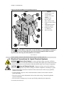
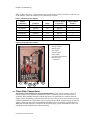
Figure 4: Rear-mounted Water and Liquid Supply Injector
Figure
Legend
1.
2.
3.
4.
5.
6.
7.
8.
9.
Assembly for 36- and
42-inch models
Assembly for 30-inch
models
Cold water inlet
Hot water inlet
Water outlet into shell
Chemical outlet into drain
sump
3/8-inch NPT chemical
connection (typical)
Flushing water inlet
(1/2-inch hose)
Water inlet mouth
.
Notice 4 : Pellerin Milnor Corporation accepts absolutely no responsibility for damage to
its equipment or to any textiles therein when concentrated chemicals dribble out of the
injection tubes onto any part of the machine or its contents.
— End of BIWUUI01 —
BICEUI01 (Published) Book specs- Dates: 20070531 / 20070531 / 20070531 Lang: ENG01 Applic: CJX
1.4. Electrical Connections for Liquid Chemical Systems
WARNING 5 : Electric Shock Hazard—Contact with high voltage electricity will kill or
seriously injure you. Even when the machine is not running, three-phase power and control circuit
power are still present at several locations within the cabinet and at some electrical components.
CAUTION 6 : Injury and Damage Hazards—Improper wiring can cause the machine to
malfunction, risking injury to personnel, damage to machine components, and damage to goods.
• Electrical and piping connections described in this section must be made only by qualified,
authorized personnel.
• Lock off and tag out power at the external disconnect switches for the washer-extractor
before proceeding.
• Do not rely merely on the information in this section when wiring. Consult all applicable
electrical schematics.
• Do not reroute or rearrange any wires not specifically permitted by this instruction.
PELLERIN MILNOR CORPORATION
Chapter 1. Commissioning
• Do not connect a common wire to ground. Use the common terminal furnished.
CAUTION 7 : Risk of Poor or Inconsistent Wash Quality—Injection times of less than 10
seconds are discouraged because fine adjustments are not possible, and factors such as pump lag
time may cause significant variations in the amount of chemical delivered.
• Size pumps or valves small enough for adequate control (i.e., for longer injection times).
• Use two pumps or valves to inject a small or large quantity of the same chemical, if
required.
Supplement 2
Maximizing Chemical Injection Precision
Injection of a consistent amount of chemical is important in controlling wash quality and using
chemicals economically. When chemicals are injected by units of time, as is done with most
washer-extractors, injections of short duration can be imprecise because of two reasons:
• Fine adjustments to the delivered quantity are not possible. For example, if an injection of
three seconds is extended by one second, the quantity delivered is theoretically increased by
more than 30 percent. However, if an injection of 20 seconds is increased by one second, the
theoretical quantity is increased by only five percent.
• Variations in the time between the start of the chemical signal and the start of the chemical
delivery into the machine can cause significant differences in the quantity of chemical
injected. In this case, if a pump starts more slowly some times than others, or if the delivery
tubes are partially empty at the start of the inject period, the quantity of chemical delivered
may vary significantly. As an example, assume a peristaltic pump moves chemical along the
delivery tube at a rate of three feet per second. If the delivery tube is empty for three feet
along its length, then one second of the injection time is spent injecting air rather than
chemical. If the programmed injection time is only three seconds, then one third of the
desired chemical is not being delivered. However, if the programmed injection time is 20
seconds, the chemical delivery is only five percent less than desired.
Increasing the programmed injection time makes any variation less significant. Use pumps
and/or valves sized to allow inject times of at least 10 seconds. If injection times for a specific
chemical vary widely from one formula to another, consider using two pumps or valves for the
same chemical. Actuate one pump for injecting small quantities, and use both pumps or valves
for larger quantities.
1.4.1.
Pump Signal Connections
The E-P Express® controller closes certain relay contacts when chemicals are desired and to flush
the chemical system after each injection. These signals are alternating current at the control circuit
voltage and cannot be made potential-free. Any device driven by this signal can draw up to 37
milliamperes.
Note 2: The manifold flush signal is effective only if the chemical supply system provided by others is
properly designed and connected to a flushing water source.
CAUTION 8 : Component Damage Hazard—Board components will burn out and require
board replacement if devices driven by inject signals do not meet the above electrical
specifications. Pumps usually draw a higher current than specified above, and will cause board
damage.
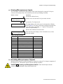
This machine provides signals for five chemicals and a manifold flush. Table 4 contains the
connection details for these signals. All chemical signal connections are available on terminal strip
PELLERIN MILNOR CORPORATION
Chapter 1. Commissioning
TBS, as shown in Figure 5. This terminal strip is located in the electrical enclosure on the left rear
of the machine, where the machine power connections are made.
Table 4: Chemical Injection Signals
Signal
Component
Chemical
Relay
Processor Board
Connection
TBS Terminal
Number
Chemical 1
Chemical 2
Chemical 3
Chemical 4
Chemical 5
Manifold Flush
Detergent
Bleach
Sour
Softener
Starch
none
K2
K5
K4
K3
K1
K9
M5-3, 1
M5-6, 1
M5-5, 1
M5-4, 1
M5-2, 1
M3-5, 1
1
2
3
4
5
6
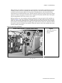
Figure 5: Pump Signal Connections
Electrical Connections Enclosure
Legend
1.
2.
3.
4.
5.
6.
7.
Detergent signal
Bleach signal
Sour signal
Softener signal
Starch signal
Chemical signal common
Machine power
connections
.
1.4.2.
Timer Stop Connections
This feature is not available on coin-operated machines. Timer stop is a feature of the E-P
Express control which stops the machine timer while a certain input to the microprocessor is
grounded. When multiple machines without this feature are connected to a common chemical
supply system, the quantity of chemical injected can vary widely if two or more machines request
chemical simultaneously. When timer stop is properly wired with the chemical supply system, the
supply system stops the timers in certain linked machines when one machine requests chemical.
When the chemical injection is completed, the chemical supply system terminates the timer stop
command, and the stopped timers resume counting.
PELLERIN MILNOR CORPORATION
Chapter 1. Commissioning
When the timer in a machine is stopped, the current formula event continues until the timer resumes
counting. If water valves are open when the timer stops, they will close when the desired level is
reached. Chemical injection signals will stop after the designated time, but the manifold flush
signal will not occur until the timer starts. All other actions (cylinder reversing, extract speed, drain
speed, etc.) that are in progress when the timer is stopped will continue until the timer starts again
and the programmed time for the current event expires.
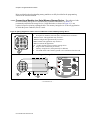
Milnor provides two wires terminated with butt connectors in the rear console of the machine, as
shown in Figure 6. One wire originates electrically from pin 6 of M5 on the processor board. The
other wire is electrically identical to pin 16 of M6 on the processor board. For timer stop to operate,
the chemical system should include a normally open contact between these two connectors. When
the contact is open, the machine runs normally. When the contact is closed, the machine timer stops
until the contact opens again.
Figure 6: Timer Stop Connections
Inside of Rear Console (T_E shown, others similar)
Legend
A.
B.
C.
Timer stop connections
Processor board
Inverter
.
— End of BICEUI01 —
PELLERIN MILNOR CORPORATION
Chapter 2. Programming
Chapter 2
Programming
BICJHC01 (Published) Book specs- Dates: 20070531 / 20070531 / 20070531 Lang: ENG01 Applic: CJX
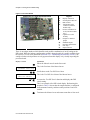
2.1. Controls on E-P Express® Washer-extractors
The controls on these Milnor® washer-extractors are predominantly membrane push-buttons, some
of which include indicator lights. Other controls include a keyswitch and a mechanical button to
unlatch the door. Some of these controls serve different functions in the three operational modes of
the machine. The function of each control in the normal, manual, and programming modes of this
machine is described in detail in this document.
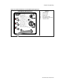
Figure 7: E-P Express Control Panel
Typical Panel
Legend
1.
2.
3.
4.
5.
6.
7.
8.
9.
10.
11.
12.
Start button
Terminate button
Manual mode button
Operator signal light
Signal cancel button
Next button
Display
Scroll up button
Scroll down button
Door unlock button
Run/program keyswitch
Run indicator light
.
2.1.1.
Control Functions During Normal Operation
Normal operation is the state of the machine when the machine control circuit is energized. The
machine may be either idle (waiting to run a formula) or running. If the machine is idle, the
message on the display will begin with “Run Formula” and include a formula number on the second
line.
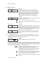
1. Press the Start button (\) to initiate the selected wash formula. The formula begins if power is
available at the machine and the loading door is closed. When the Start button is held depressed
while the Scroll Up button is pressed, the machine displays the status of the microprocessor
inputs for troubleshooting.
PELLERIN MILNOR CORPORATION
Chapter 2. Programming
2. The Terminate button (z) cancels all remaining steps in any running formula and initiates the
shutdown procedure for the machine. Formulas ended in this manner cannot be resumed.
3. The Manual mode button (`) has no effect while a formula is running. Pressing this button
when the display says “Run Formula xx” initiates manual mode, where the controls function as
described in Section 2.1.2 “Control Functions During Manual Operation”.
4. The Operator signal light, in the upper left corner of the Signal cancel button (x), is a visual
indicator that operator attention is required. This light is illuminated simultaneously with the
sounding of the operator signal buzzer.
5. Press the Signal cancel button (x) to silence the operator signal buzzer which sounds when a
formula completes normally. Also, if a signal is programmed with a chemical injection in any
formula, this button must be pressed to indicate that the chemical has been added and to resume
operation.
6. The Next button (y) is not used during normal operation.
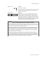
7. The display on these machines is a vacuum fluorescent type displaying two lines of twenty
characters each.
8. The Scroll up button (v) functions in much the same manner as the Scroll down button
described above. Press this button to display the next higher numbered formula in memory. For
troubleshooting, hold the Manual button and press the Scroll up button to view the status of the
first 12 outputs. Hold the Start button and press the Scroll up button to view the status of the
microprocessor inputs.
9. When selecting a specific formula to run, press the Scroll Down button (w) to display the next
lower numbered formula in memory. Press this button with the lowest formula displayed
(Formula 01) to select the highest numbered available formula (maximum of 30 formulas). For
troubleshooting, hold the Manual button and press the Scroll Down button to view the status of
the second 12 outputs.
10. The Door unlock button (') releases the door lock, allowing the latch on the door to operate.
Hold this button depressed and press firmly on the door latch lever to open the door for load
and unloading.
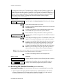
11. The Run/program keyswitch must be in the Run position (R) unless the machine is being
configured or programmed. All control descriptions listed under Section 2.1.1 “Control
Functions During Normal Operation” are based on the keyswitch being in the Run position.
Refer to Section 2.1.3 for descriptions of how the controls operate with the keyswitch in the
Program position (P).
12. The Run Indicator light, in the upper left corner of the Start button, is illuminated when a
formula is started by pressing \. If the operator terminates the formula before it runs to
completion (with z), the light goes off when any coast time expires and the door is unlocked.
If the formula runs to completion, the light goes off when the coast time following the final
extract step expires.
2.1.2.
Control Functions During Manual Operation
Manual operation is used primarily for troubleshooting the machine by activating outputs and
viewing inputs.
1. The Start button (\), when pressed while the Manual button is held down, activates the
selected menu function. Depress the Start and Manual buttons simultaneously to view the
software date code. For other manual menus, release the Start button when the menu appears
on the display.
2. The Terminate button (z) cancels manual mode and returns the controller to the normal
operation or programming mode, depending on the setting of the Run/Program keyswitch. Any
outputs that were manually actuated while in manual mode are turned off.
PELLERIN MILNOR CORPORATION
Chapter 2. Programming
3.
4.
5.
6.
7.
8.
9.
10.
11.
12.
2.1.3.
Use the Manual button (`) to enter manual mode when the machine is idle.
The Operator Signal light does not operate when the controller is in manual mode.
The Signal Cancel button (x) has no function in manual mode.
The Next button (y) has no function in manual mode.
In the Manual menu, the display presents user prompts and selected information. The software
date code and machine configuration are displayed; inputs and outputs and their respective
statuses are shown in those modes. Other menu selections display DIP switch settings, as well
as temperature and level testing information.
The Scroll Up button (v) displays the next higher numbered mode in the manual menu. For
example, pressing this button once will scroll from the Software Date Code mode to the Test
Inputs mode.
At the manual menu, the Scroll Down button (w) displays the available menu items in reverse
numeric order.
The Door unlock button (') unlocks the door latch. The function of this button is the same
whether the machine is in normal operating mode or manual mode.
The Run/Program keyswitch has no effect on how the manual mode operates. However, the
status of the switch (either + or –) is displayed in field F in the Test Inputs menu.
The Run Indicator light is not activated during manual operation.
Control Functions During Programming
The programming mode is used to modify the actions performed in a wash formula or to create new
wash formulas.
1. The Start button (\) is used in combination with the Next button (y) or the Terminate button
(z) to delete or insert a step in a wash formula, respectively.
2. The Terminate button (z) returns the user to the main programming menu (top line of display
reads Program X Menu) from the Add/Change Formula and the Standard Formulas menus.
The Terminate button has no effect after the Configure menu has been accessed, or after any
parameter of any formula has been accessed in the Add/Change Formula menu.
3. The Manual button is not used in the programming mode.
4. The Operator Signal light is not used in the programming mode.
5. The Signal Cancel button is not used in programming.
6. Use the Next button (y) to confirm any choice and move to the next decision in the sequence.
7. The display presents the programming menus and choices within those menus, including all
configuration and formula parameters.
8. The Scroll Up button (v) scrolls the available choices upward from the lowest available
number.
9. Use the Scroll Down button (w) to change the selected programming parameter to the next
lower-numbered choice.
10. The Door unlock button (') has no function in programming mode.
11. The Run/Program keyswitch allows programming when set to P. The Program menu
includes selections for adding and changing wash formulas, configuring the controller, and
restoring the standard formulas provided with the machine. The keyswitch must be set to the
Run position (R) for normal machine operation, as described in Section 2.1.1 “Control
Functions During Normal Operation”.
PELLERIN MILNOR CORPORATION
Chapter 2. Programming
12. The Run Indicator light is not actuated during programming.
— End of BICJHC01 —
BICJHC02 (Published) Book specs- Dates: 20070531 / 20070531 / 20070531 Lang: ENG01 Applic: CJX
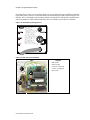
2.2. Selecting an Industry Formula Set
The Milnor® factory configures each E-P Express® washer-extractor controller for the industry
specified by the purchaser when the machine is ordered. The configuration process consists of
setting the DIP switches on the processor board and may include installing the appropriate industry
nameplate on some models. At the owner's discretion, the DIP switch settings controlling the
available formulas may be changed in the field, and new industry nameplates may be obtained from
your dealer or the Milnor® parts department.
To change industry configuration, turn the machine off. Then lock off and tag out power to the
machine at the wall disconnect before accessing the processor board.
DANGER 9 : Electrocution hazard—Contact with electric power can kill or seriously injure
you. Electric power is present inside the cabinetry unless the main machine power disconnect is
off.
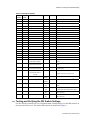
The location of the DIP switches on the microprocessor board are shown in Figure 8, as are
examples of the on and off positions. Set the switches to the desired configuration according to
Table 5. Turn the machine on; the display will show the current configuration.
CAUTION 10 : Risk of improper configuration—On some machines, the processor board is
installed in the control box so that the labels printed on the DIP switch appear inverted.
• Do not assume that the switch is right side up. Always reference the labels (OFF, ON, 1, 2,
etc.) printed on the switch when setting DIP switches.
Figure 8: Location of DIP Switches
Processor Board
Legend
A.
B.
1.
2.
3.
4.
DIP switch
Board identification area
OFF
ON
ON
OFF
DIP Switch (Partial View)
.
PELLERIN MILNOR CORPORATION
Chapter 2. Programming
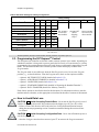
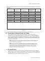
Table 5: DIP Switch Settings for Industry Configurations
Switch Settings
Industry Configuration
S1
S2
S3
S4
S5
S6
S7
S8
Correctional Facilities
ON
ON
ON
ON
OFF
ON
ON
ON
Hotels and Motels
On
Athletic Laundries
ON
OFF
ON
ON
These switches
prevents/Off
This
switch
is
OFF OFF
ON
ON
Healthcare Facilities
not used in
allows
are not used in
ON
ON
OFF
ON these models.
Restaurants
skipping
these models.
steps.*
Commercial Laundries
OFF
ON
OFF
ON
ON
OFF OFF
ON
Shirt Laundries
OFF OFF OFF
ON
Offshore Laundries
Fire-Fighter
ON
ON
ON
OFF
* Setting S6 off enables the operator to cancel any step in progress except a drain before an extract.
— End of BICJHC02 —
BICJXP01 (Published) Book specs- Dates: 20070531 / 20070531 / 20070531 Lang: ENG01 Applic: CJX
2.3. Programming the E-P Express® Control
The microprocessor controller used in this washer extractor operates in two modes, depending on
whether the machine is being used to process goods (the Run mode or Formula menu) or is being
programmed with operating characteristics to be used when a wash formula is started (the Program
mode). This document describes the available operator actions and display feedback in the
Program mode.
The Program mode is accessible only when the Run/Program keyswitch is set to the Program
position (P), as described below. From the Program menu, there are four options available:
• Option 0: OK TURN KEY TO RUN (detailed in Section 2.3.2)
• Option 1: ADD/CHANGE FORMULA (detailed in Section 2.3.3)
• Option 2: CONFIGURE (detailed in Section 2.3.4)
• Option 3: STANDARD FORMULAS (detailed in “Restoring the Standard Formulas”)
• Option 4: DATA TRANSFER (detailed in “Memory Transfer”)
Each of these options is described in detail in this document. For information on how to start the
machine and run a formula, see the appropriate section listed in the table of contents of this manual.
2.3.1.
How to Avoid Data Loss
CAUTION 11 : Avoid Corrupting Formula Data—Never turn the Run/Program keyswitch
from the Program position to the Run position unless the display says OK Turn Key to Run.
• Failure to follow this direction will result in the loss of all formula modifications entered
during the current programming session. Formulas not modified during this session will not
be affected.
CAUTION 12 : Avoid Corrupting Configuration Data—Never shut off machine power to
exit the Program mode.
• Once the Configure menu has been accessed, press \ to return to the Program menu and
PELLERIN MILNOR CORPORATION
Chapter 2. Programming
save all changes before turning off machine power.
Use the following procedures to clear corrupted formula and configuration memory and restore
valid data.
Display or Action
Explanation
CHECKSUM ERROR
TURN KEY TO PROGRAM
P
Clears all memory and accesses the first configuration decision.
First configure decision.
LANGUAGE ?
0=ENGLISH 0
2.3.2.
This display indicates that all memory will be cleared. The
machine controller must be reconfigured and any new
formulas or modifications to standard formulas must be
re-programmed.
How to Return to Run Mode
Option 0 allows for a safe return from the Program mode to the Formula menu, preserving any
changes that were made during the programming session and maintaining the integrity of
programming and configuration data.
Display or Action
Explanation
PROGRAM 0 MENU
OK TURN KEY TO RUN
P
This is Option 0 of the Program menu. From this display, return
to the Formula menu or select another available menu option.
Returns to Run mode (Formula menu)
or
v/w
2.3.3.
Scrolls the available choices in the Program menu.
How to Add or Change a Formula
Washer extractors with the Milnor® E-P Express® control system have the capacity for up to 30
unique wash formulas. The space for these formulas is allocated in memory whether or not the
formulas are actually used.
The user interface employs similar procedures for creating a new formula and for changing an
existing formula. Both procedures are detailed below, in Section 2.3.3.3 and Section 2.3.3.5. The
control system will inform the person programming the machine whether the selected formula has
already been programmed.
2.3.3.1.
Quick Reference for E-P Express Programming—This part of this document briefly
describes how to program a wash formula. For a more detailed description of navigating through
the programming capabilities of this controller, see Section 2.3.3.2. More information on creating
and deleting formulas is in Section 2.3.3.3 and Section 2.3.3.4, respectively. Section 2.3.3.5
describes how to modify an existing formula, and Section 2.3.3.6 explains each programming
decision.
1. Apply power to the machine.
2. After the normal power-up display and start-up safety delay, turn the Run/Program keyswitch
to the Program position (P).
3. Scroll (v / w) to ADD/CHANGE FORMULA and press the Next button (y) to confirm your
choice.
PELLERIN MILNOR CORPORATION
Chapter 2. Programming
4. Scroll (v / w) to an unused formula number (01 through 30) to add a new formula. The cursor
will flash on “CHANGE.”
5. Press the Next button (y) to confirm your choice.
6. Select the type of step (TT) from the available options (00 through 14).
Tip:
At this point, you can delete the formula by setting the type of step for Step 01 to “00.”
7. Press the Next button (y) to confirm your choice and advance to the next decision (MMQ).
8. Scroll the first (tens) digit to the desired value, then press the Next button (y) to confirm your
choice and advance to the next digit.
9. Scroll the second (units) digit to the desired value, then press the Next button (y) to confirm
your choice and advance to the next digit.
10. Scroll the third (quarter-minutes) digit to the desired value, then press the Next button (y) to
confirm your choice and advance to the next decision.
11. For chemical injection in any bath step, use the scroll buttons (v / w) to enable or disable each
chemical. Enable a chemical for injection by setting its value to 1; disable a chemical by setting
its value to 0. Press the Next button (y) after each chemical selection to confirm your choice
and advance to the next chemical.
Tip:
Press the terminate button (z) to cancel the current choice and move the cursor to the previous
decision.
12. Repeat this procedure for each step in the formula.
13. After the last desired step in the formula (usually an extract), add a step of type 00 to mark the
end of the formula. The controller returns to the Add/Change Formula menu.
2.3.3.2.
Moving through the Operations and Decisions—Each step is completely
programmed on a single display:
Display or Action
F14 TT MMQ C:12345
S01 00
PELLERIN MILNOR CORPORATION
Explanation
In this example, “F14” at the left end of the display represents the
formula number. “S01” below it represents the step number
within that formula. When programming a formula position (e.g.,
Formula 14) for the first time, the TT field (type of step) will
always be 00 (end formula) until you change it to another valid
type of step.
Chapter 2. Programming
2.3.3.3.
How to Create a New Formula—Creating a new formula with the E-P Plus® controller
entails adding and defining steps in one of the blank formula slots.
Display or Action
Explanation
PROGRAM 1 MENU
ADD/CHANGE FORMULA
y
w/v
Formula 23 is available for adding because it does not currently
exist.
ADD/CHANGE FORMULA
07 FORMULA NUMBER 07
Formula 07 is available for changing because it already exists.
Accesses the selected formula for programming. Valid formula
numbers are 01 through 30.
Formula 07, Step 01 selected for programming.
F07 TT MMQ C:12345
S01 00
How to Delete a Formula
Display or Action
Explanation
Delete an existing formula by making step 01 an End Formula
step. Set the TT value for step 01 of the formula to 00.
F03 TT MMQ C:12345
S01 00
2.3.3.5.1.
Scrolls the available formula numbers. If the selected formula
number hasn't already been programmed, it is selected for add. If
the number has already been programmed, it is selected for
change, as shown in the following two displays.
ADD/CHANGE FORMULA
23 FORMULA NUMBER 23
y
2.3.3.5.
Accesses the formula list for selection of a formula number to
change or create.
This is the Add/Change Formula display. From this display, either
back up to the Program menu, or begin creating or changing a
formula.
ADD/CHANGE FORMULA
00 RETURN TO MENU
2.3.3.4.
This is Option 1 of the Program menu. From this display, either
access a formula by number to change or create, or select another
available menu option.
How to Change a Formula
How to Insert or Delete a Step in an Existing Formula
Display or Action
Explanation
When there is no cursor blinking on the display, steps can be
reviewed, added or deleted.
F03 TT MMQ C:12345
S01 06 070
11000
\
START+NEXT/TERM TO
INS/DELETE THIS STEP
y/z
Provides a help screen for inserting and deleting steps, as shown
below.
This is the help screen for inserting and deleting steps. Steps can
only be inserted or deleted while the help screen is present, i.e.,
the \ button is depressed.
Insert or delete steps if the Insert/Delete Step help screen is
visible.
PELLERIN MILNOR CORPORATION
Chapter 2. Programming
2.3.3.5.2.
Inserting a Step
Display or Action
Explanation
\+y
Duplicates the selected step to the next numerical position. If this
is Step 01, the duplicated step becomes Step 02 and all the
following steps move to the next higher numerical position.
Duplication of End Formula or Extract steps is prevented by the
controller.
F03 TT MMQ C:12345
S01 NEW STEP01 DUPED
2.3.3.5.3.
This display indicates that the new step has been created as a copy
of the previous step. Chemicals and injection times are not copied
into the new step.
Deleting a Step
Display or Action
Explanation
\+z
Deletes the selected step. The next step becomes the current step
by assuming the number of the step that was just deleted. All
following steps move one number lower.
Deletion of End Formula is prevented in all cases. A Bath step can
not be deleted if it falls between two Extract steps.
This display indicates that the selected step has been deleted from
the wash formula.
03 TT MMQ C:12345
01 STEP DELETED
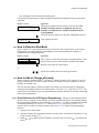
2.3.3.5.4.
How to Save Changes—The control automatically saves the changes when you answer “Yes”
to “End Formula #xx?”
Display or Action
Explanation
Fxx TT TYPE OF STEP
Sxx 00 End Formula
y
END FORMULA #xx ?
0 NO [1=YES]
2.3.3.6.
2.3.3.6.1.
Step type 00 indicates that the formula is finished.
Accepts the selected step type (00 = End Formula) and prompts
for confirmation to end the formula.
Confirmation display for end of formula. Select “0 NO” by
pressing yto continue programming this formula. Select “1
YES” by pressing w then y to save this formula and return to the
menu system.
The Step Decisions
TT = Step Type
Display or Action
F12 TT MMQ C:12345
S01 03 SPLIT SOAK
PELLERIN MILNOR CORPORATION
Explanation
This is an example of a formula programming display with the
Step type field selected. There are 15 types of steps available for
programming, although every step type is not available in every
condition. For example, an extract operation can never be the first
step in a formula nor immediately follow another extract. Press w
or v to scroll to the desired step type, then press y to choose the
selected step type and move to the step time decision.
Chapter 2. Programming
2.3.3.6.1.1.
End of formula (TT=00)—This is the last step of any formula. When you program an End of
formula step by entering 00 End of formula and pressing y, the controller saves the programmed
formula and returns to the Add/Change Formula screen.
2.3.3.6.1.2.
Soak (TT=01, 02, or 03)—Soaking serves to expose the goods to water and any included
chemicals without mechanical action which might damage certain textiles. In this machine, all
soak baths are performed at high water level and the selected waters (hot, cold, or split). Any
chemicals may be injected.
The step timer begins counting when high level is achieved and continues for the programmed
amount of time. When the step time expires, the controller commands the motor to turn the cylinder
clockwise for four seconds at wash speed, then to accelerate to drain speed. A few seconds after the
cylinder reaches drain speed, the drain opens. The next step begins after the fixed drain time and
coast time expire. Coast time is not counted if the next step is an extract.
01=Hot soak—Use hot soaks to maximize the activity of the injected chemicals when there is little
or no chance of stains being set by the high temperature. Temperatures above 120 degrees
Fahrenheit (49 degrees Celsius) usually make the removal of protein-based soils more difficult.
02=Cold soak—Use cold soak steps for goods that contain protein stains. The low temperature is
usually less effective than higher temperatures at activating certain chemicals, but the chance of
setting stains is much lower.
03=Split soak—If the temperature of incoming hot water alone is higher than 120 degrees
Fahrenheit (49 degrees Celsius), soaking with both hot and cold water simultaneously will
remove more soil than a cold flush. A split soak is also less likely to set protein stains than a hot
soak if the temperature of the split fill is consistently lower than 120 degrees Fahrenheit.
2.3.3.6.1.3.
Flush (TT=04, 05, or 06)—A flush is usually used early in a formula, prior to bleaching, to
dilute and remove debris and loose soil before chemicals are added. Flushes are also used to raise or
lower the temperature of the goods. Machines with the E-P Express® controller conduct all flushes
at high water level with the programmed waters (hot, cold, or split). Any chemicals may be
injected, although this is not common.
For any flush operation on the E-P Express® controller, the step timer begins counting when high
level is achieved and continues for the programmed time. The cylinder reverses at wash speed
while the step timer is counting down. When the step time expires, the controller commands the
motor to turn the cylinder clockwise for four seconds at wash speed, then to accelerate to drain
speed. A few seconds after the cylinder reaches drain speed, the drain opens. The next step begins
after the fixed drain time and coast time expire. Coast time is not counted if the step about to begin
is an extract.
04=Hot flush—Use hot flushes to remove the maximum amount of debris and loose soil when
there is little or no chance of stains being set by the high temperature. Temperatures above 120
degrees Fahrenheit (49 degrees Celsius) usually make the removal of protein-based soils more
difficult.
05=Cold flush—Use one or more cold flush steps to remove debris and loose soil from goods that
might contain protein stains before adding detergent. The low temperature is likely to be less
effective than higher temperatures at removing certain types of soil, but the chance of setting
stains is much lower.
06=Split flush—If the temperature of incoming hot water is higher than 120 degrees Fahrenheit
(49 degrees Celsius), flushing with both hot and cold water simultaneously will remove more
soil than a cold flush. A split flush is also less likely to set protein stains than a hot flush if the
temperature of the split fill is consistently lower than 120 degrees Fahrenheit.
2.3.3.6.1.4.
Wash (TT=07, 08, or 09)—Wash steps include break, suds, bleach suds, and carryover
PELLERIN MILNOR CORPORATION
Chapter 2. Programming
operations, and occur after the final flush if one or more flushes are used. All wash steps
programmed with this controller use low water level. The first step to introduce chemicals to the
machine cylinder is usually called a break and includes the injection of alkali and detergent. Suds
and bleach suds steps follow the break step.
Carryover steps use the chemicals retained in the goods after draining the previous step to prolong
chemical contact at a higher temperature without introducing more chemicals. The drain prior to a
carryover step also removes suspended soil and reduces bath alkalinity for better bleaching.
07=Hot wash—This step type causes the machine to fill exclusively through the hot water valve.
Generally, the bath temperature should be as hot as is practical for suds baths, with some
considerations. While higher temperatures increase the effect of detergents, there is a risk of
setting certain stains if they were not sufficiently removed with earlier, cooler baths. High bath
temperatures may also introduce creases into some synthetic fabrics by heating the fibers above
the temperature at which they become plastic. When this happens, rapid cooling will often set
the creases beyond the ability of other equipment to remove them. For the best effect, introduce
chlorine bleach when the bath temperature is about 150 degrees Fahrenheit (66 degrees Celsius).
Bleaching with chlorine at temperatures above 160 degrees Fahrenheit (71 degrees Celsius) is
likely to damage fibers.
08=Cold wash—This step type uses only water at or near the temperature at which it entered the
plant. In especially warm climates, this water may be at or above the temperature achieved by
using split water in other areas. Program a cold wash any time the split water temperature might
cause undesired results, including wrinkles or fiber damage.
09=Split wash—This type of step fills the machine by fully opening both the hot and cold water
valves simultaneously. This results in the fastest possible fill and a bath temperature that is
satisfactory for many applications. While certain factors such as pressure differences between
hot and cold water supplies cannot be predicted, the approximate temperature of split water will
be one half of the total of both the hot and cold water temperatures.
2.3.3.6.1.5.
Rinse (TT=10, 11, or 12)—Bath operations between the bleach step and the finish step are
usually called rinses. Rinses serve to remove the last of the loosened soil and most of the chemicals
from the goods. In machines with the E-P Express® controller, rinse steps are always performed
at high water level and the programmed temperature. This controller also allows the injection of
any desired chemicals during rinse operations.
10=Hot rinse—Rinsing with hot water removes more detergent and other chemicals from the
goods than a cold or split rinse, but also may have many of the same adverse affects as a hot
wash. Consider the temperature of the hot water supply and the goods being laundered when
programming this type of step.
11=Cold rinse—Use a cold rinse to remove most of the remaining chemicals from the goods
without the energy cost of hot water. Keep in mind, however, that a cold bath immediately
following a hot bath may thermoset creases in some synthetic fabrics.
12=Split rinse—Because both the hot and cold water valves are open for a split rinse, the fill time
is approximately half of the time required for either a hot or cold rinse. Also, there is less chance
for fabrics to crease than with a hot rinse, and more remaining soil and chemicals are removed
than with a cold rinse.
2.3.3.6.1.6.
Finish (TT=13)—The finish operation is usually the final bath operation of the wash formula.
This controller allows the injection of any chemical, with sour, starch, and softener being the most
common. The bath level is always low, and the water temperature is almost always cold. In
locations where the incoming cold water is so cold that chemicals do not mix readily with the
water, the machine can be configured to fill all finish steps with split water.
2.3.3.6.1.7.
Extract (TT=14)—Extract operations are used between bath steps to remove water, chemicals,
PELLERIN MILNOR CORPORATION
Chapter 2. Programming
and suspended soil; and as the final operation in a formula to remove water for faster drying.
2.3.3.6.1.8.
Quick Reference for Step Types
Table 6: Summary of Step Types
Step Name
Flush
Wash
Rinse
Finish
Extract
0
0
0
0
0
0
0
0
0
0
1
1
1
Temperature
Basket Motion
Basket Speed
N/A
N/A
N/A
Hot
None
None
Cold
Split
Hot
Wash speed
Reversing
Cold
Split
Hot
Wash speed
Reversing
Cold
Split
Hot
Wash speed
Reversing
Cold
Split
Cold (see
1 3
Wash speed
Reversing
Note)
1 4
N/A
Clockwise
Extract speed
A configuration decision allows the filling of finish steps for all
Note:
formulas with either cold or split water.
End of Formula
Soak
TT Code
0
1
2
3
4
5
6
7
8
9
0
1
2
PELLERIN MILNOR CORPORATION
Chapter 2. Programming
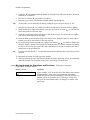
2.3.3.6.2.
MMQ = Step Time
Display or Action
Explanation
F12 TT MMQ C:12345
S01 06 032 03:30
Typical programming display for step time. When the wash
formula is running, the step timer begins counting from 00:00
when level is achieved for a bath step, or when the controller
commands extract speed. The timer causes the current step to end
when the programmed time elapses. Time is programmed in
minutes, minutes, and quarter-minutes, with a maximum
programmable time for each step of 633 (63 minutes and 45
seconds).
F12 TT MMQ C:12345
S01 06 020 00:00
First digit of step time field selected to change. v increases value
of this digit; w decreases value.
y
Accepts value for this digit and selects next digit.
z
Cancels the current selection and moves the cursor to the previous
selection.
Display or Action
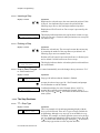
2.3.3.6.3.
Explanation
F12 TT MMQ C:12345
S01 06 080 08:00
Typical display after pressing y to accept “0” as the first minutes
digit, then pressing w two times and y once to select “8” as the
second minutes digit. The controller is waiting for user input for
quarter-minutes. The programmed time in minutes and seconds is
displayed next to the programming fields.
F12 TT MMQ C:12345
S01 06 081 08:15
Select the number of quarter-minutes desired, then press y to
accept the desired step time and begin programming chemical
injections.
C = Chemicals—All types of steps other than extract and end of formula allow chemical
injection. The duration of the injection signal for each chemical is 30 seconds unless chemical 1 is
configured for another value as described in Section 2.3.4.2.
Display or Action
Explanation
Typical programming display for chemical injection.
F12 TT MMQ C:12345
S03 06 081
00000
The E-P Express® controller provides five separate injection signals and one manifold flush signal.
Consult the person responsible for connecting the chemical supply system to the machine (usually
the chemical supplier) for information on which chemical is connected to each signal. Record the
chemical connection information in Table 7 for future reference.
v/w
Toggles the selected chemical signal between 0 (off) and 1 (on).
In each step all programmed chemicals are signalled
simultaneously when the desired level is achieved. The chemical
manifold flush signal activates 20 seconds after the chemical
injection signal ends, and continues for 30 seconds.
y
Accepts the current on/off status for the selected chemical signal
and advances to the next signal. After programming chemical 5,
this action advances to the next step in the formula.
z
Cancels the current selection and moves the cursor to the previous
decision.
PELLERIN MILNOR CORPORATION
Chapter 2. Programming
Table 7: Chemical Signals and Supplies
Chemical Signal
(from display)
Chemical Name
1
2
3
4
5
2.3.4.
(usually detergent)
(usually bleach)
(usually sour)
(usually softener)
(usually starch)
How to Configure the Controller
Because the microprocessor control system used in this machine is capable of multiple languages
and operating with many different chemical injection systems, each machine must be configured.
This configuration informs the microprocessor of what language to use for displaying operator
information and the duration of the inject time for chemical one.
CAUTION 13 : Configure Data may be Lost—If the controller loses power either
accidentally or intentionally while in the Configure mode, all configuration data may be corrupted.
Reconfigure the controller at installation and any time a memory error is detected.
2.3.4.1.
Moving through the Configure Screens
Display or Action
Explanation
This display indicates that the controller is in Program mode with
the Configure menu selected for access.
PROGRAM 2 MENU
CONFIGURE
y
LANGUAGE ?
0=ENGLISH
0
CHEM 1 INJ TIME: SSS
FORMULA 01
030
Accesses the Configure menu and displays the first configuration
decision.
The language option that appears here may vary according to how
the controller was last configured.
The value that appears here may vary according to how the
controller was last configured. These values are always reset to 30
seconds whenever the standard formulas are restored, as described
in “Restoring the Standard Formulas” (see table of contents).
y
Accepts the displayed selection.
z
Accepts the displayed selection and reverts to the previous
configure decision.
PELLERIN MILNOR CORPORATION
Chapter 2. Programming
2.3.4.2.
The Configure Decisions
Display or Action
Explanation
LANGUAGE ?
0=ENGLISH
0
w/v
Display of Language configuration decision. The language
chosen here controls all programming and operational prompts on
the machine display.
Scrolls the available languages, listed below.
0 = English
1 = Spanish
2 = French
3 = German
4 = Dutch
5 = Italian
6 = Portuguese
y
COLD OR SPLIT FINISH
0=COLD [1=SPLIT]
0
v or w
y
TIME TO DRAIN
MIN=030 MAX=255
SSS
060
Accepts the selected value for the current decision and advances
the cursor to the next decision. This action is required for each
configuration decision.
As described in Section 2.3.3.6.1.6, the finish step for all formulas
can be configured to fill with either cold water or split water (both
hot and cold). If you find that finish chemicals, especially starch,
don't mix well with cold water, set this decision to fill all finish
steps with both hot and cold water. The split fill decision is more
commonly used in cold climates.
Toggles the selection between “0=COLD” and “1=SPLIT.”
Accepts the current selection and advances to the next configure
decision.
When the machine must be installed where draining is
accomplished through solid piping instead of a drain trough,
additional time may be required to completely drain the water
from the machine. This decision sets the time after the drain opens
until the controller signals the inverter to accelerate to extract
speed. If low level is still achieved when this time expires, an error
stating “Too Long to Drain” is displayed. The minimum value is
30 seconds; the maximum value is 255 seconds (4:15).
CAUTION 14 : Motor damage and inverter fault hazard—The motor may be damaged
and/or the inverter may trip frequently if the drain time is not long enough to allow most of the free
water to exit the machine before extract begins.
• Factory testing has found that a drain time of 60 seconds provides some margin of safety for
a machine that drains freely into an open trough. Increase drain time if the machine drains
into an enclosed pipe, especially if that same pipe might simultaneously drain additional
machines.
PELLERIN MILNOR CORPORATION
Chapter 2. Programming
Display or Action
Explanation
v or w
y
Display or Action
CHEM 1 INJ TIME: SSS
FORMULA 01
030
Scrolls the selected digit.
Accepts the currently selected digit and advances to the next digit.
Advances to the next configure decision if pressed when the
rightmost digit is selected.
Explanation
Display of Chem 1 inject time configuration decision. Some
chemical systems use the duration of the chemical 1 injection
signal to determine which wash formula is running. Only the
injection time for chemical 1 is configurable; all other chemical
signals are fixed at 30 seconds. By default, Chem 1 inject time for
each formula is 30 seconds until changed. The minimum value is
1 second; the maximum value is 255 seconds (4:15).
Supplement 3
About Chemical Injection with the E-P Express Controller
The normal duration for all chemical injection signals from this controller is 30 seconds.
This period often allows delivery of the desired amount of chemical when pump sizes and other
factors are used to control chemical volume more precisely.
Installations requiring more precise chemical metering may use programmable chemical supply
systems (provided by others) to select chemical amounts according to the washer-extractor
formula. Typically these chemical systems use the duration of the washer-extractor injection
signal for Chemical 1 to determine which formula is running, then select the corresponding
chemical program for that wash formula.
When the chemical supply system determines the wash formula and selects the appropriate
chemical program for quantities, the chemical system still needs to know when to inject each
chemical. The chemical system monitors the washer-extractor controller for chemical signals in
each step calling for chemicals. When the washer-extractor requests a specific chemical, the
chemical supply system injects the programmed quantity of that chemical.
PELLERIN MILNOR CORPORATION
Chapter 2. Programming
For example, the E-P Express® controller may be configured so the Chemical 1 signal is five
seconds in formula 01, ten seconds in formula 02, and 15 seconds in formula 03. When the
washer-extractor controller signals for Chemical 1 to be injected, the Chemical 1 output relay is
turned on for the configured duration. The chemical injection system then determines which
formula the washer-extractor is running and selects the chemical injection program
corresponding to the wash formula.
Display or Action
Explanation
CHEM 1 INJ TIME: SSS
FORMULA 01
030
v/w
Typical display with formula number field selected for change.
Scrolls the formula number up or down.
y
Accepts the selected formula number and moves the cursor to the
injection time field.
z
Accepts the current digit of the formula number and moves the
cursor back to the previous decision (Time to Drain).
\
Writes all data to memory and returns to the Program menu.
CHEM 1 INJ TIME: SSS
FORMULA 04
030
v/w
Typical display with the first digit of the time field for formula 4
selected.
Scrolls the selected digit up or down. The maximum value for any
signal is 255 seconds; the minimum value is 000 (no injection).
y
Accepts the current digit of the inject time and moves the cursor
forward to the next digit. When the third digit is selected, the
cursor advances to the formula number for the next formula.
z
Accepts the current digit of the inject time and moves the cursor
back to the previous digit. If the first digit of the inject time is
selected, the previous decision (Time to Drain) is displayed.
Note 3: All inject times return to the default value of 30 seconds any time the standard formulas are restored
to memory. The procedure for restoring standard formulas is described below.
\
Display or Action
Accepts the current digit and saves all configure data.
Explanation
Appears while the controller writes all configure data to memory.
***PLEASE WAIT***
PROGRAM 2 MENU
CONFIGURE
2.3.5.
Indicates that all configure data was successfully written to
memory. Select another program menu option to continue.
Restoring the Standard Formulas [Document BICJUP01]
Programming mode 3 allows the owner/operator with access to a programming key to perform
either of these two actions:
1. Option 0 replaces all existing formulas with the factory default formulas for the selected
industry configuration. This selection replaces formulas 1 through 10 with the standard
industry formulas and removes all data from formulas 11 through 30.
PELLERIN MILNOR CORPORATION
Chapter 2. Programming
2. Option 1 replaces only formulas 1 through 10 with the standard industry formulas. This leaves
any user-programmed data in formulas 11 through 30 intact.
CAUTION 15 : Avoid Data Loss—Other than the two methods described above, it is not
possible to selectively delete field-modified or field-programmed formulas with this programming
mode. This mode erases all field-programmed formulas 1 through 10 or 1 through 30 as specified.
For selective deletions and modifications, use Program mode 1 (Add/Change Formula).
CAUTION 16 : Avoid Chemical Damage to Goods—The injection time for Chemical 1 is
30 seconds for all default formulas. This may prevent certain chemical supply systems from
properly detecting which formula is running, or cause the injection time for chemical 1 to be longer
than intended.
• Always verify the Chemical 1 injection time for each formula after restoring the standard
formulas.
PELLERIN MILNOR CORPORATION
Chapter 2. Programming
Figure 9: Procedure for Restoring Standard Formulas
Process Flow Chart
Legend
1
4
2
3
13
5
6
9.
10.
11.
7
12.
13.
14.
15.
3
14
4
8
3
9
4
15
10
11
12
.
PELLERIN MILNOR CORPORATION
1.
2.
3.
4.
5.
6.
7.
8.
Start
Restore standard formulas?
Yes
No
Enable Program menu
Select Program Mode 3
Enable Program Mode 3
Clear formulas 11 through
30?
Select Default 30 Formulas
Confirm selection
Standard formulas written
to memory
Return to Run menu
Terminate process
Abandon operation?
Select Default 10 Formulas
Chapter 2. Programming
The remainder of this document details the procedure for restoring the industry standard formulas
on models employing the Milnor® E-P Express® controller.
Display or Action
Explanation
PROGRAM 0 MENU
OK TURN KEY TO RUN
v/w
Scrolls available choices (0 through 3) in the Program menu.
This is Option 3 of the Program menu.
PROGRAM 3 MENU
STANDARD FORMULAS
y
Accesses the Standard Formulas option of the Program menu.
CORRECTIONAL LAUNDRY
0 DEFAULT 30 FORMULA
Option 0 (Default 30 Formulas) of the Standard Formula menu
effectively deletes all 30 formulas, then replaces formulas 1
through 10 with the factory-supplied standard formulas for the
configured industry. Formulas 11 through 30 are replaced with
blank formulas.
CORRECTIONAL LAUNDRY
1 DEFAULT 10 FORMULA
Option 1 (Default 10 Formulas) deletes only formulas 1 through
10 and replaces them with the factory-supplied standard formulas
for the configured industry. Formulas 11 through 30 are not
modifed with this selection.
v/w
z
y
CORRECTIONAL LAUNDRY
** PLEASE WAIT **
PROGRAM 3 MENU
STANDARD FORMULAS
v/w
PROGRAM 0 MENU
OK TURN KEY TO RUN
Ry
RUN FORMULA
00 OK TO POWER OFF
Scrolls the available choices (0 Default 30 Formulas or 1 Default
10 Formulas).
Cancels this procedure without changing or deleting any
formulas.
If the procedure is cancelled, the display returns to Option 3 of the
Program menu.
PROGRAM 3 MENU
STANDARD FORMULAS
2.3.6.
This is Option 0 of the Program menu. From this display, either
return to Run mode or select another menu item.
From either option 0 or option 1, defaults the selected set of
formulas: 1 through 30, or 1 through 10.
Appears for approximately five seconds as the standard formulas
are written to memory.
Replaces the previous display when the process is completed.
Scroll to Program menu item 0 before exiting Program mode.
This is Program menu item 0. It's now safe to turn the
Run/Program keyswitch to the Run position.
Returns to Formula menu.
Formula menu; run a formula or shut down the machine.
Data Transfer (Option 4) [Document BICJUP13]
Certain Milnor® controllers described in this manual can transfer memory between the machine
and a Milnor serial memory storage device or between two machines. Refer to Table 8 to determine
the hardware and software requirements for memory transfer. See Section 5.3. “Construction of
External Serial Link Cables” for inter-machine cable specifications and assembly instructions.
PELLERIN MILNOR CORPORATION
Chapter 2. Programming
Table 8: Controllers Capable of Transferring Memory
Machine
Controller
Typical Machine
Models
E-P Express
E-P Express
Gear Guardian
30015T_X, 30022T_X
E-P Plus
30015V_J, 36026V_J,
42026V_J
30015H_J, 30022H_J
30022X_J
Controller Software
Later Than
Processor Board Later
Than
WUEPXPRSA/22004
WUT5XGGA/22GGF
08BH18EPYT REV. K
WUV7J1B/2200K
WUH7J1A/2200E
all versions
08BH18EPDT REV. K
CAUTION 17 : Configuration data will be overwritten.—When transferring data from one
machine to another, the formulas and configuration data of the Master machine will be written to
the Slave machine. Partial memory transfer is not possible.
• Record all configure data from the Slave machine before beginning the download,
especially “Offset Height.” Restore this value to the Slave machine after the download is
finished.
• For best results both machines in a machine-to-machine transfer must be identical models
with identical options and controller software, and industry configuration (e.g., 36026V6J
with steam, hot and cold water; software version WUV7J1B/2200K; and configured for
Commercial Laundry facilities).
Notice 18 : For data transfer to succeed, the processor boards on all included washer-extractors
must have the Milnor part number specified in Table 8 with the specified software installed.
• The Milnor part number for the processor board appears on a white sticker near the Milnor
logo on the processor board.
• The revision level of the processor board is white lettering stamped directly on the green
circuit board, located below the part number sticker. Look for “REV. K.”
• The processor board software version appears on a white label affixed to one of the large
integrated circuit components on the processor board.
PELLERIN MILNOR CORPORATION
Chapter 2. Programming
Figure 10: Controls Identification on Serial Memory Storage Device
Serial Memory Storage Device
Legend
A.
B.
C.
D.
E.
F.
Transmit light
Receive light
Ready light
Data transfer cable
Clear Memory keyswitch
Transmit button
.
PELLERIN MILNOR CORPORATION
Chapter 2. Programming
2.3.6.1.
Establishing the Required Connections
Display or Action
Explanation
Turn off power to the machine before connecting the serial
memory storage device or connecting the two machines together.
Connect the storage device to the machine, or the two machines
together, using the 9-pin round connector.
Apply power to the machine(s). The storage device receives
power through the connector from the power supply in the
machine.
Turn the key on the storage device to Clear Memory, then return
the key to the normal vertical position. This process is handled
automatically when transferring from one machine to another.
The Ready light on the storage device will remain off until the
clearing process is complete. The clearing process is fully
automatic and requires no user action beyond turning the key to
Clear Memory and returning it to the normal position.
When the Ready light comes on again (after about 45 seconds),
the storage device is ready to accept data from the machine
controller.
CAUTION 19 : Ensure Data Integrity—Clear the memory storage device before saving data
to it.
• The memory storage device will hold all programming and configuration data for one
machine, and can be re-used many times. However, this device will only accept new data
when it's empty.
• Attempts to save data to a storage device that has not been cleared will fail, even if the
procedure appears successful.
When the Run Program display appears, switch from Run mode
to Program mode.
RUN PROGRAM
00 OK TO POWER OFF
P
PROGRAM 0 MENU
OK TURN KEY TO RUN
w
PROGRAM 4 MENU
DATA TRANSFER
PELLERIN MILNOR CORPORATION
Turn the Run/Program keyswitch on the machine controller(s)
from the Run position to the Program position.
Controller display when the Run/Program keyswitch is set to P
(Program position).
Scroll down in the Program menu to Data Transfer. If two
machines are connected together, this is required at both
machines.
This is the Data Transfer menu selection. Follow the procedure in
Section 2.3.6.2 for making a copy of good data from the machine
controller. Refer to Section 2.3.6.3 for instructions on restoring
previously saved data from the storage device (or another
machine) to the machine controller, as might be required after
changing the processor board.
Chapter 2. Programming
2.3.6.2.
Saving Data from the Machine to the Storage Device or a Second Machine
Display or Action
Explanation
y
Confirms selection and advances to the Data Transfer menu.
DOWN LOAD DEVICES
0 MACHINE<==>MACHINE
This is the Data Download sub-menu. Select the desired type of
data transfer here.
DATA TRANSFER
0 SLAVE
There are two selections available in the Data Transfer menu:
0=Slave and 1=Master.
v
For saving information to the data storage device or another
machine, select 1=Master at the machine controller. If two
machines are connected, establish the one which will receive the
data as the slave, and the sending machine as the master.
The machine controller is set as the Master device, making the
storage device the slave.
DATA TRANSFER
1 MASTER
Note 4: The Master device is always the sender and controls when the data transfer starts. The Slave device
is always the receiver and should be established and waiting for data before the Master device is confirmed.
Notice 20 : Do not send data to the memory storage device until the storage device is cleared and
ready to receive. The Ready light must be on when transfer begins or the stored data will not be
valid.
y
PLEASE WAIT
AC35
TRANSFERRING DATA
Confirms selection of the machine controller as the Master and
immediately begins the transfer. All receiving (slave) machines
must be established before the master machine is designated.
While the data transfer is occurring, the four digits at the top right
of the display scroll rapidly as the machine controller sends data.
The Receive light on the storage device illuminates when the data
transfer begins, indicating that it is receiving data. The display on
the slave machine scrolls quickly as data is accepted.
Note 5: Transfer times may vary somewhat, but the average is about 75 seconds.
COMPLETED
0000
TRANSFERRING DATA
This display indicates that the machine controller delivered the
data to the storage device.
The Receive light on the storage device goes off when the transfer
successfully ends. If all three lights on the storage device begin
blinking at any time during the transfer, the data being received by
the storage device is invalid. Clear the memory in the storage
device and perform the transfer again.
PELLERIN MILNOR CORPORATION
Chapter 2. Programming
Display or Action
Explanation
CAUTION 21 : Data Corruption Hazard—If the machine controller indicates that the data
transfer is complete but the Receive light on the data storage device is still illuminated, invalid data
is stored in the storage device.
• Do not rely on the data in the storage device unless the machine controller indicated that the
transfer completed, AND the Receive light on the storage device turned off automatically.
• Do not restore data from the storage device to the machine if the data is invalid. Restoring
invalid data from the storage device to the machine controller will overwrite any formulas
that have been changed or created since the data was last stored. These formulas can not be
recovered.
z
Acknowledges that the data transfer is complete and returns to the
Program menu.
Data Transfer menu display. Scroll to Program menu item 0, then
turn the Run/Program keyswitch to the Run position.
PROGRAM 4 MENU
DATA TRANSFER
v
PROGRAM 0 MENU
OK TURN KEY TO RUN
R
RUN PROGRAM
00 OK TO POWER OFF
Scroll the Program menu selections.
From item 0 of the Program menu, return to normal operating
mode.
Return to normal operating mode. Press y if necessary to confirm
that the key is at Run.
The Run Program display appears to indicate that it is safe to turn
the machine off.
Turn off power to the machine(s).
Disconnect the memory storage device, remove the key, and put
both in secure locations. For two machines, remove the
connecting cable.
PELLERIN MILNOR CORPORATION
Chapter 2. Programming
2.3.6.3.
Restoring Saved Data to the Machine from the Storage Device or Another
Machine
Display or Action
Explanation
Turn off power to the machine(s) before connecting the serial
memory storage device.
Connect the storage device to the machine using the 9-pin round
connector. For two machines, use a serial cable constructed as
described in Section 5.3. “Construction of External Serial Link
Cables”.
Apply power to the machine(s). The storage device receives
power through the connector from the power supply in the
machine.
When the Run Program display appears, switch from Run mode
to Program mode.
RUN PROGRAM
00 OK TO POWER OFF
P
PROGRAM 0 MENU
OK TURN KEY TO RUN
w
Turn the Run/Program keyswitch on the machine controller(s)
from the Run position to the Program position.
Controller display when the Run/Program keyswitch is set to P
(Program position).
Scroll down in the Program menu to Data Transfer.
This is the Data Transfer menu selection. Follow the procedure in
Section 2.3.6.2 for making a copy of good data from the machine
controller.
PROGRAM 4 MENU
DATA TRANSFER
y
Display or Action
Confirms selection and advances to the Data Transfer menu.
Explanation
The machine controller is set as the Slave device, making the
storage device the Master. The Master device always controls
when the data transfer starts and sends the data to the slave
device. If transferring data from one machine to another, the slave
machine will receive the data sent from the master.
DATA TRANSFER
0 SLAVE
y
DATA TRANSFER
** PLEASE WAIT **
PLEASE WAIT
0000
RECEIVING DATA
Confirms the selection of the machine controller as the Slave
device.
Appears for three seconds as the machine controller prepares
machine memory to accept data from the storage device. When
this display appears, all memory in the machine controller is
cleared.
This display indicates that the machine controller is polling the
data storage device for incoming data. The four characters at the
right end of the top line show the memory location currently being
written. These characters remain at “0000” until the transfer
begins.
Press the Transmit button on the data storage device or confirm
the Master setting on the sending machine to begin the transfer.
PELLERIN MILNOR CORPORATION
Chapter 2. Programming
Display or Action
Explanation
As soon as the Transmit button on the data storage device is
pressed (or y on the master machine), the storage device begins
sending a continuous data stream to the slave machine controller.
The machine display shows the progress of this display in the four
characters on the top line. The transfer is complete when the
display shows “FFFF.”
The Transmit light on the data storage device turns off when the
transfer completes.
E-PXPRESS/TxX SYSTEM
CORRECTIONAL LAUNDRY
Appears for about one half second as the machine controller
updates all memory.
CONFIG CHKSUM 1234
FORMULA CHKSUM 4321
Appears briefly (about one half second) as the machine controller
verifies that the checksums calculated for the downloaded data
match the checksums sent by the data storage device.
COMPLETED
This display indicates that the data received by the machine
controller matches exactly the data sent by the storage device. The
data transfer was successful.
0000
z
Acknowledge that the data transfer is complete and returns to the
Program menu.
Data Transfer menu display. Scroll to Program menu item 0, then
turn the Run/Program keyswitch to the Run position.
PROGRAM 4 MENU
DATA TRANSFER
v
PROGRAM 0 MENU
OK TURN KEY TO RUN
R
RUN PROGRAM
00 OK TO POWER OFF
Scroll the Program menu selections.
From item 0 of the Program menu, return to normal operating
mode.
Return to normal operating mode. Press y if necessary to confirm
that the key is at Run.
The Run Program display appears to indicate that it is safe to turn
the machine off.
Turn off power to the machine(s).
Disconnect the memory storage device, remove the key, and put
both in secure locations.
— End of BICJXP01 —
PELLERIN MILNOR CORPORATION
Chapter 3. Operating
Chapter 3
Operating
BICJHO01 (Published) Book specs- Dates: 20070531 / 20070531 / 20070531 Lang: ENG01 Applic: CJX
3.1. Running a Formula
3.1.1.
Applying Power
Display or Action
Explanation
R
The Run/Program keyswitch must be set to the Run position
before the main wall disconnect (fuse or circuit breaker) is closed
to provide power to the machine.
When power is first applied to the machine, the display shows the software copyright information,
machine name, and the checksum number. The checksum number changes with any programming
change. To detect unauthorized programming, record the checksum at the end of each authorized
programming session and compare it to the checksum displayed at each power up.
Milnor® washer extractors with E-P Express® controls do not use a speed sensing device to verify
that the basket has stopped rotating. Therefore, when power is first applied to the machine, at least
80 seconds must elapse before any further operations can be attempted. This provides sufficient
time for the basket to coast to a complete stop if power was lost while the machine was in high
speed extract and restored before the basket stopped.
DANGER 22 : Entanglement Hazard—The linen inside or hanging partially outside a turning
cylinder can suddenly wrap around your hand, arm, or body. The inertia of the spinning cylinder
can cause the entangled linen to twist off or sever body parts. You can be killed or seriously
injured.
• Never put any part of your body inside this machine or touch the linen while the machine is
turning.
3.1.2.
3.1.2.1.
Selecting and Starting the Formula
Load Machine and Close Door—Load the machine to the rated capacity and securely close
the loading door. Review Determining Load Size (the related section in document BIWUUO01, or
see the table of contents) for guidelines on loading machines.
PELLERIN MILNOR CORPORATION
Chapter 3. Operating
3.1.2.2.
Selecting a Formula
Display or Action
Explanation
This is the Run Formula display. From this display, the operator
can disconnect power from the machine without risking damage
to electronic parts, or he can select a formula to run, as described
below.
RUN FORMULA
00 OK TO POWER OFF
v
indexes forward through the 30 formulas.
w
indexes backward through the 30 formulas.
RUN FORMULA
07 FORMULA NUMBER 07
\
starts the machine with the selected formula.
indicates that the formula selected for running has not been
programmed or is not available. This display appears for three
seconds.
RUN FORMULA
DOES NOT EXIST
3.1.3.
Example display: Formula 07 selected for running.
Unloading the Machine
How a formula ends may depend on whether the formula finishes without interruption or is
terminated manually.
DANGER 23 : Entanglement Hazard—The linen inside or hanging partially outside a turning
cylinder can suddenly wrap around your hand, arm, or body. The inertia of the spinning cylinder
can cause the entangled linen to twist off or sever body parts. You can be killed or seriously
injured.
• Never put any part of your body inside this machine or touch the linen while the machine is
turning.
When a formula ends normally or is terminated, the door remains locked while the cylinder coasts
to a stop. The door unlocks 80 seconds after the formula ends.
Display or Action
Explanation
display during the coast period when a formula ends.
UNLOCKING THE DOOR
** PLEASE WAIT **
At the end of the coast time, the operator alarm sounds.
WAITING TO UNLOAD
U
x
PELLERIN MILNOR CORPORATION
Silences the operator alarm. The door unlocks, and the machine
may be unloaded.
Chapter 3. Operating
3.1.4.
The Display During Automatic Operation
Display or Action
Explanation
23:04 STEP# 01 02:37
CHEM 1+2
025
These two displays alternate during normal operation while any
chemical injection signal is enabled. The number on the right end
of the bottom line indicates the number of seconds remaining in
the longest programmed injection.
23:04
23:04 is the time remaining in the formula.
23:04 F02S01 02:37
L=A1/D1 Hot Wash
F02S01
02:37
F02S01 indicates that the current formula is 02 (F02) and the
current step is 01 (S01).
02:37 is the time remaining in this step.
23:04 EXTRACT
02:37
EXTRACT indicates that the machine is currently executing an
extract.
TIMEHALT indicates that the timer is stopped while a chemical
is being injected. The chemical supplier must connect equipment
for this option.
L=A0/D2
L=A0/D2 indicates that level 1 (low level) has not been achieved,
and level 2 is desired. A1/D2 indicates that level 1 is achieved, but
level 2 (high level) is desired.
Hot Rinse
The programmed step type appears to the right of the level
indicator. The step type includes the temperature range, indicating
which water valves are used to fill the machine.
3.1.5.
How to Shorten, Terminate, or Suspend a Running Formula
Display or Action
Explanation
y+\
Cancels a step. Advances the step timer to zero for any bath, a
drain not followed by an extract, or any extract in progress. The
next step begins automatically.
This operation is possible only if DIP switch 6 on the processor
board is in the off position, allowing the cancelling of steps.
z
RUN FORMULA
00 OK TO POWER OFF
Cancels the current formula and returns the machine to the Run
Formula display.
This is the Run Formula display. The door interlock delay,
described in Section 3.1.3, must expire before the door can be
opened.
PELLERIN MILNOR CORPORATION
Chapter 3. Operating
3.1.6.
How to Restart after Power Loss
The E-P Express® control remembers the formula and step it was executing if power fails or if the
wall disconnect is turned off while the machine is operating in automatic mode.
Display or Action
Explanation
PRESS START TO RUN
STEP xx - FORMULA yy
\
On most machine models, this display appears when power is
restored. The formula and step which were in progress when
power was interrupted are shown.
Resumes the formula at the displayed formula and step. If the
outage occured in a bath step, level must again be satisfied, even if
it wasalready satisfied before power was lost. Any commanded
chemicals will be injected again.
If the outage occured during a drain, that step will be repeated,
then followed by the next commanded step.
If the outage occured during an extract step, the previous bath will
be repeated before the extract step begins.
z
3.1.7.
Terminates the formula in progress.
How the Flush Valve Works
The E-P Express® controller provides an output signal that activates the flush valve for 20 to 30
seconds 15 seconds after the last chemical injection for each bath ends. If a bath is shortened or
terminated before or while this valve is energized, the flush valve will be turned off. Shortening or
terminating a bath may prevent the flush valve from activating.
— End of BICJHO01 —
BICJUD01 (Published) Book specs- Dates: 20070531 / 20070531 / 20070531 Lang: ENG01 Applic: CJX
3.2. Viewing and Clearing the Formula Count Accumulator
The microprocessor controller increments a discrete counter for each formula near the end of the
formula. This count is maintained until the counter is cleared. The maximum number of times a
formula can be counted before resetting the accumulator is 999, after which the count will remain at
999 until cleared. The count for each formula can only be viewed and/or cleared while the machine
is in the Run mode but not running a formula (machine is idle).
CAUTION 24 : Avoid Corrupted Accumulator Data—The accumulated data can be
corrupted or become inaccurate if power is lost for an extended period of time, the maximum count
of 999 is reached, or the memory is corrupted by electrical interference.
• Apply power to the machine for at least 15 seconds every 48 hours to retain the formula
count. See “Important Owner/User Information” for more detailed information.
• To help ensure an accurate count, record the value and clear each accumulator before it
reaches 999 counts.
• If the display shows “Accumulator Error,” the count for all formulas must be cleared. See
the document on error messages for more information.
PELLERIN MILNOR CORPORATION
Chapter 3. Operating
Display or Action
Explanation
This is the normal display at power-up.
RUN FORMULA
00 OK TO POWER OFF
w/ v
Selects a formula by indexing forward/backward through the
formula numbers (01-30).
With any formula selected,
y
RUN FORMULA
038
05 FORMULA NUMBER 05
y+z
Displays the count in the upper right corner of the display.
This example shows that 38 loads were processed with formula 05
since the counter was reset.
Clears the count for the selected formula.
— End of BICJUD01 —
PELLERIN MILNOR CORPORATION
Chapter 4. Testing and Troubleshooting
Chapter 4
Testing and Troubleshooting
PELLERIN MILNOR CORPORATION
Chapter 4. Testing and Troubleshooting
BICJHT01 (Published) Book specs- Dates: 20070531 / 20070531 / 20070531 Lang: ENG01 Applic: CJX
4.1. Error Messages
4.1.1.
Error Messages at Power Up
If an error message appears during power up, the error must be cleared before the machine can be
run or programmed.
Display or Action
Explanation
The microprocessor performs a memory check each time the
machine is turned on. This error message appears if the
microprocessor detects that the accumulator data is corrupt, in
which case all accumulators must be reset to zero.
ACCUMULATOR ERROR
TERMINATE TO CLEAR
z
CHECKSUM ERROR,
TURN KEY TO PROGRAM
Resets all accumulators and clears the error message. See
“Viewing and Clearing the Formula Count Accumulator” (see
Table of Contents) for more information.
Appears if there is illegal data in the configuration, formula, or
industry memory areas. Use the following procedure to clear this
error.
1. Reconfigure the machine according to the configuration information in “Programming the E-P
Express® Control” (see Table of Contents).
2. Reinstall the standard (default) formulas according to the default formula loading procedure in
“Programming the E-P Express® Control”.
3. Reprogram any lost wash formulas according to “Programming the E-P Express® Control”.
MEMORY: FLASH
IS NOT TALKING
This message appears when the microprocessor cannot read from
the flash memory.
1. Lock off and tag out power to the machine.
2. Replace flash memory. Contact the Milnor® factory to ensure that the replacement memory is
the most current version for your machine.
3. Restore power to machine.
4. Reconfigure the machine according to the configuration information in “Programming the E-P
Express® Control” (see Table of Contents).
5. Reinstall the standard (default) formulas according to the default formula loading procedure in
“Programming the E-P Express® Control”.
6. Reprogram lost wash formulas according to “Programming the E-P Express® Control”.
PELLERIN MILNOR CORPORATION
Chapter 4. Testing and Troubleshooting
4.1.2.
Error Messages during Normal Operation
If an error message appears on the bottom line of the display while the machine is running, the
timer shown on the top line will stop counting. When the error is corrected, the timer resumes
counting down. To troubleshoot most errors, suspend the formula in progress and turn power off.
Do not terminate the formula if it is to be resumed after the error is corrected. See Section 3.1.5
“How to Shorten, Terminate, or Suspend a Running Formula” for more information.
Display or Action
DOOR NOT CLOSED
Explanation
This error message indicates that the door input is not made while
the machine is running. Verify that the door is closed, then check
the door switch and its connection to the microprocessor. Press
\ if necessary to resume operation after the error is corrected.
Never operate this machine while this message is present.
CHECK LEVEL SWITCH
The level switch may be faulty, perhaps reporting that level 2 was
achieved before level 1. Check the pressure transducer, or the
level switch and its input connection to the microprocessor.
LEVELS STILL MADE
The microprocessor is still receiving information that a level is
made just before or during an extract step, or immediately before
the fill for a bath step. This error is self-clearing when level is lost.
TOO LONG TO FILL
Time to fill to level exceeded 10 minutes. Check the water valves,
strainers, supply lines, and water pressure. The machine will
continue to fill until level is reached, at which time the error will
automatically clear and normal operation will resume.
TOO LONG TO DRAIN
EXTERNAL FAULT
The machine did not drain properly in the allotted drain time. This
self-correcting error will clear when the water level in the basket
is low enough to begin the next operation. The drain time before
this message appears is controlled by a configure decision. See the
related section in document BICJUC01.
On most machines, this error indicates that the programmed
chemical injection failed, usually because the chemical supply
system is empty. When chemicals are added and can be injected,
this error clears automatically, allowing operation to resume.
On 48040F7J/F7B models, this error indicates that the bearing air
pressure is below the minimum required to help protect the
bearing from water contamination.
THREE WIRE DISABLED
The three-wire relay de-energized. This relay provides control
circuit power to the machine. Once energized by momentarily
depressing the Start button, it is held energized by its own
normally open contacts, along with motor overloads, door
interlocks, etc. Should any of these contacts open even
momentarily, the machine stops and this display appears. This
error can only be cleared by depressing the Start button, and only
then if the error has been cleared.
INVERTER FAULT
This error message appears if the microprocessor does not receive
an input from the inverter within 14 seconds of the beginning of
the formula. After 14 seconds without an inverter input, the timer
stops, the basket is stationary, and the drain valve opens. To
recover, press the Next key (y).
PELLERIN MILNOR CORPORATION
Chapter 4. Testing and Troubleshooting
Display or Action
VIBRATION SW TRIPPED
RECOVERY SEQUENCE
Explanation
When the vibration switch closes, the timer stops. After 45 to 85
seconds, the basket reverses at wash speed as the cylinder fills
with water. When low level is achieved, the cylinder reverses for
one additional minute at wash speed, then accelerates to extract
speed.
— End of BICJHT01 —
BICJHT03 (Published) Book specs- Dates: 20070531 / 20070531 / 20070531 Lang: ENG01 Applic: CJX
4.2. The E-P Express® Manual Menu
4.2.1.
4.2.1.1.
The Manual Menu
Components—The Manual menu contains these selections:
1. Software Date Code—a display of the software type and date code, both of which are fixed in
the software; and the industry type, which is determined by setting the DIP switches on the
processor board.
2. Test Inputs—allows viewing of microprocessor inputs for testing when a formula is not
running. Devices, including the door latch and the level transducer, provide signals to the
microprocessor by grounding certain inputs. The status of these inputs can be monitored in this
mode, and changes to the input status will appear instantaneously. Refer to Section 4.2.6 to
view the status of inputs while the machine is operating.
3. Test Outputs—allows the actuation of outputs for testing when a formula is not running.
Outputs are signals from the microprocessor to other devices, such as chemical pumps and
motor contactors. Refer to Section 4.2.6 to view the status of outputs while the machine is
operating.
4. Test DIP Switch—displays a hexadecimal number which is unique for each possible setting of
the DIP switch. This number can be used with the appropriate tables to determine the industry
configuration of the machine, as well as whether the machine is configured to allow the
operator to skip certain steps during automatic operation.
PELLERIN MILNOR CORPORATION
Chapter 4. Testing and Troubleshooting
4.2.1.2.
How to Access the Manual Menu
Display or Action
Explanation
The machine must be idle (power on, but not running a formula)
before the Manual menu can be accessed. Also, the Run/Program
keyswitch must be at the Run position (R).
RUN FORMULA
00 OK TO POWER OFF
`
MANUAL MENU
1 SOFTWARE DATE CODE
v/w
z
Scrolls forward/backward through the available modes of the
Manual menu.
Returns to the Run mode.
How to Return to the Run Mode from the Manual Menu
Display or Action
Explanation
`
MANUAL MENU
1 SOFTWARE DATE CODE
z
Enters the Manual menu from Run mode.
This is the Manual menu display.
Exits the Manual menu to the Run mode.
This is the Run mode display. Select a formula to run, or turn off
machine power.
RUN FORMULA
00 OK TO POWER OFF
4.2.2.
Reverse type indicates blinking cursor position. Select one of the
Manual menu modes or return to the Run mode, as described
below.
Run mode selected; control is awaiting selection of a valid
formula number. The formula number that was selected when the
Manual menu was accessed appears on the display.
RUN FORMULA
00 OK TO POWER OFF
4.2.1.3.
Accesses the Manual menu.
Determining the Software Version
Display or Action
Explanation
`
MANUAL MENU
1 SOFTWARE DATE CODE
`+\
Accesses the Manual menu.
Manual menu accessed and Software date code mode selected.
Hold both buttons depressed to view the software date code and
machine configuration information, as shown below.
E-P EXPRESS/T 21001
HEALTHCARE LAUNDRY
Machine style (/T = T_X), software date code (21001), and
configuration (Healthcare Laundry).
RUN FORMULA
xx FORMULA NUMBER xx
Run mode display is restored when the ` + \ button
combination is released.
PELLERIN MILNOR CORPORATION
Chapter 4. Testing and Troubleshooting
4.2.3.
Viewing Microprocessor Inputs
The on/off state of each input to the microprocessor can be displayed by using the Test Inputs
selection of the Manual menu. The machine must be idle (not running a formula).
Display or Action
Explanation
`
Accesses the Manual menu.
Manual menu accessed and Test Inputs mode selected.
MANUAL MENU
2 TEST INPUTS
`+\
ABCDEFGHIJKLMNOP (-)
+--++----+----+- OFF
z
Accesses the Test Inputs mode.
The input display code on the top row corresponds to a display
code in Table 9. The status of the input is displayed beneath each
code. If the input is grounded, a “+” appears. Non-grounded
inputs are represented by “–”.
Restores the controller to the Run mode.
This is the Run mode display. Select a formula to run, or shut
down the machine.
RUN FORMULA
00 OK TO POWER OFF
Table 9: E-P Express Inputs
4.2.4.
Display Code
Input Name
Connector-Pin
A
Door closed
M6-1
B
Low water level
M6-9
C
Vibration switch tripped
M6-2
D
Input from Inverter
M6-10
E
High water level
M6-3
F
Keyswitch in Program position
M6-11
G
not used
M6-4
H
Halt—external fault
M6-12
I
Halt—bath time
M6-5
J
not used
M6-13
J
Door open desired
M6-13
K
not used
M6-6
L
not used
M6-14
Actuating Microprocessor Outputs
Machine functions may be tested individually or in groups by using the Test Outputs component of
the Manual menu. The machine must be idle (not running a formula).
DANGER 25 : Crushing and Entanglement Hazard—Bare manual outputs actuate
washer-extractor mechanisms. Keep all personnel clear.
PELLERIN MILNOR CORPORATION
Chapter 4. Testing and Troubleshooting
Display or Action
Explanation
`
Accesses the Manual menu.
This is the Manual menu display with the Test Outputs component
selected.
MANUAL MENU
3 TEST OUTPUTS
`+\
TEST OUTPUTS
01 INJECT CHEMICAL 5
v/w
Accesses the output testing selection.
This is the Output testing display.
Indexes forward and backward through the output names, as
shown in Table 10.
Example display with output in place to be selected and
subsequently actuated.
TEST OUTPUTS
07 COLD WATER VALVE
\
Accesses the selected output for actuation. All outputs are initially
disabled when accessed.
Example display with output accessed and disabled.
COLD WATER VALVE
0=OFF 1=ON
0
\
COLD WATER VALVE
0=OFF 1=ON
1
\
COLD WATER VALVE
0=OFF 1=ON
0
v
HOT WATER VALVE
0=OFF 1=ON
0
z
RUN FORMULA
00 OK TO POWER OFF
PELLERIN MILNOR CORPORATION
Enables the output (turns the output on).
Example display with output enabled. The cold water valve is
open.
If the output was already on, this keystroke turns it off.
Example display with output disabled. The cold water valve is
closed.
Disables (turns off) the output if it was previously enabled, and
advances to the next output.
Display after pressing v to advance to the next output.
Disables the output if it was enabled, then returns to the Run
mode.
Display of Run mode.
Chapter 4. Testing and Troubleshooting
Table 10: E-P Express Outputs
Output Page-Co
Number
lumn
4.2.5.
Description
Device
MTA
Consequences of Actuation
1
0-a
Inject chemical 5
K1
5-2/5-11
Operates inject device for chemical 5
2
0-b
Inject chemical 1
K2
5-3/5-1
Operates inject device for chemical 1
3
0-c
Inject chemical 4
K3
5-4/5-1
Operates inject device for chemical 4
4
0-d
Inject chemical 3
K4
5-5/5-1
Operates inject device for chemical 3
5
0-e
Inject chemical 2
K5
5-6/5-1
Operates inject device for chemical 2
6
0-f
Hot water valve
K6
3-2/3-1
Opens valve
7
0-g
Cold water valve
K7
3-3/3-1
Opens valve
8
0-h
Drain solenoid
K8
3-4/3-1
Closes drain
9
0-i
Flush valve
K9
3-5/3-1
Opens flush valve
10
0-j
not used
K10
3-6/3-1
11
0-k
not used
K11
3-7/3-1
12
1-a
not used
K12
3-8/3-1
13
1-b
not used
K13
3-9/3-1
14
1-c
not used
K14
3-10/3-1
15
1-d
not used
K15
3-11/3-1
16
1-e
not used
K16
3-13/3-14
16
1-e
Door lock
K16
3-13/3-14
17
1-f
Unlock door
K17
3-15/3-16 Energizes door latch to unlocked position
18
1-g
not used
K18
3-18/3-17
19
1-h
Extract speed (use only
with empty cylinder)
K19
3-19/3-17
Locks door and turns cylinder at extract
speed.
20
1-i
Distribution (drain) speed
(Door must be closed)
K20
3-20/3-17
Locks door and turns cylinder at drain
speed.
21
1-j
Clockwise wash speed
(Door must be closed)
K21
3-21/3-17
Locks door and turns cylinder clockwise
at wash speed.
22
1-k
Counter-clockwise wash
speed (Door must be
closed)
K22
3-22/3-17
Locks door and turns cylinder
counter-clockwise at wash speed.
23
0
Buzz signal
Signal on
board
none
Sounds operator alarm
24
0
Run light
Light on
board
none
Turns on light in Start button (\)
25
0
Reversing wash speed
Functional
test
none
Locks door and reverses cylinder at wash
speed.
26
0
High extract speed
Functional
test
none
Locks door and turns cylinder clockwise
at wash speed, then high extract speed.
27
0
Fill to level 1
Functional
test
none
Locks door, closes drain, fills to level 1
with cold water.
28
0
Fill to level 2
Functional
test
none
Locks door, closes drain, fills to level 2
with cold water.
Testing and Verifying the DIP Switch Settings
For all E-P Express models, the set of default formulas is determined by how the DIP switches on
the processor board are set. The bank of DIP switches is identified in Figure 11.
PELLERIN MILNOR CORPORATION
Chapter 4. Testing and Troubleshooting
Figure 11: Processor Board
Photograph of Typical Processor Board
Legend
A.
B.
C.
D.
E.
F.
G.
.
H.
I.
J.
K.
Display connectors
Switch panel connector
DIP switches
Temperature probe
connector (E-P Plus
models only)
Pressure transducer for
level (E-P Plus models
only)
Capacitor to retain
memory
Outputs to chemical
pumps
Standard outputs
Operator signal buzzer
CPU chip
Input connector
There is one unique number which identifies each possible combination of on/off settings at the
DIP switch. While the industry configuration (switch 1 through switch 4) is readily available from
the Software version mode (described in Section 4.2.2 “Determining the Software Version”), the
settings of other switch positions are only apparent from this display or by visually inspecting the
processor board.
Display or Action
Explanation
`
MANUAL MENU
1 SOFTWARE DATE CODE
w, w
Enters the Manual menu from the Run mode.
This is the first item of the Manual menu.
Scrolls down to the Test DIP Switch item.
This is the Test DIP Switch item of the Manual menu.
MANUAL MENU
4 TEST DIP SWITCH
`+\
Accesses the Test DIP Switch function and displays the DIP
switch setting.
This is an example of the DIP switch display. Referencing this
number in Table 11 shows that the sample machine is configured
for Restaurants Laundry, and that switch positions 5 and 6 are
enabled.
052
z
PELLERIN MILNOR CORPORATION
Terminates the Manual menu and returns controller to Run mode.
Chapter 4. Testing and Troubleshooting
Table 11: Interpretation of Test DIP Switch Display
4.2.6.
Industry
Configuration
Standard
Display Value
Value if
Position 5 is
ON
Value if
Position 6 is
ON
Value if Both
Positions 5
and 6 are ON
Correctional
Hotel/Motel
Athletic
Healthcare
Restaurants
Commercial
Shirt Laundry
Offshore
Fire-Fighter
0
1
2
3
4
5
6
7
8
16
17
18
19
20
21
22
23
24
32
33
34
35
36
37
38
39
40
48
49
50
51
52
53
54
55
56
Viewing Inputs and Outputs while Machine is Operating
While the machine must be idle to actuate outputs, inputs and outputs can be viewed (but not turned
on or off) while the machine is operating.
Display or Action
Explanation
23:04 F02S01 02:37
L=A1/D1 Hot Wash
\+v
This is a typical display while the machine is running a formula.
displays the inputs. A plus sign (+) indicates the input is
grounded, while a minus sign (–) indicates the input is not
grounded.
typical display of input status while the machine is running. Refer
to Table 10 to determine which input is represented by each
character on the display.
ABCDEFGHIJK
+++-------`+v
displays the first 11 outputs (Page 0). A plus sign (+) indicates the
output is actuated, while a minus sign (–) indicates the output is
turned off.
`+w
displays the last 11 outputs (Page 1).
PAGE abcdefghijk
0
-+----+----
typical display of first page of outputs (Page 0) while the machine
is running. Refer to Table 10 to determine the component
represented by each character on Page 0 and Page 1.
— End of BICJHT03 —
PELLERIN MILNOR CORPORATION
Chapter 5. Supplemental Information
Chapter 5
Supplemental Information
BICJUF01 (Published) Book specs- Dates: 20070531 / 20070531 / 20070531 Lang: ENG01 Applic: CJX
5.1. The E-P Express® Hardware
The Milnor® E-P Express® microprocessor control is designed specifically for Milnor®
washer-extractors. Along with certain external electromechanical relay logic and sensing devices,
it controls all machine and system functions. Not every Milnor® microprocessor system includes
all the following components.
5.1.1.
5.1.1.1.
5.1.1.2.
Keyswitches
Run/Program Keyswitch—This keyswitch allows controlling who has the necessary access
to modify wash formulas. Formulas can be modified only when this switch is turned from the Run
position (R) to the Program position (P). To safeguard wash formulas, keep this key in a secure
place with restricted personnel access.
Automatic/Test Keyswitch—E-P Express models are not equipped with an Automatic/Test
keyswitch.
5.1.2.
Display
Machines with the E-P Express® control use a vacuum fluorescent display consisting of two lines
of 20 characters each. This type of display is easily identified by green characters on a black
background when operating, or a nearly black background when not operating.
5.1.3.
Power Supply
The power supply serves to provide a regulated specific voltage to the processor board and certain
auxiliary boards and devices. It converts control circuit alternating current voltage to +12 volts
direct current, –12 volts direct current, and +5 volts direct current. The power supply is switchable
between 120 volts and 240 volts alternating current input voltage.
Although the +12VDC and –12VDC are not adjustable, the +5VDC is rather sensitive and the
power supply must be adjusted so the actual voltage at the processor board is between 5.04VDC
and 5.06VDC as measured by an accurate digital voltmeter. If this voltage is not within the stated
range, the machine is likely to malfunction.
5.1.4.
CPU Processor Board
The central processing unit (CPU) processes data received from the various inputs, stores
information, and responds to each pushbutton entry with the appropriate action. Data is stored in
PELLERIN MILNOR CORPORATION
Chapter 5. Supplemental Information
one or more of the following types of memory chips on the CPU board, depending on the machine
model.
SRAM—Static Random Access Memory stores the accumulator (formula count) data as long as
the machine has power, or via a capacitor for approximately 24 hours with power off. This type
of component is also used to retain the last formula and step in progress when power is turned
off at the machine while a formula is running. SRAM is used in all E-P Plus® and E-P Express®
controllers.
Flash Memory—Similar to EEPROM memory in function, flash memory can be electrically
erased and reprogrammed, but is faster and can retain more data than EEPROM memory. Flash
memory is used on processor boards for F_J, H_J, X_J, and V_J models, as well as all E-P
Express® models. The two flash memory chips reside in sockets IC2 and IC12. The chip in
socket IC12 contains operating instructions and the complete set of industry standard formulas.
As software updates are made available, the owner/operator may choose to replace this chip.
The chip in socket IC2 holds the industry formulas and user changes to those formulas, as well
as machine configuration data. The chip in socket IC2 will not normally need replacing for
software updates.
5.1.5.
Outputs
Depending on the processor board, output relays may be either socket-mounted to a separate output
board, or permanently soldered to the processor board.
Machines in the E-P Express® model lines use the 188 processor board with output relays soldered
to the processor board. These relays are SPST (single pole, single throw) with contacts capable of
faithfully conducting a maximum of 25VA. The output voltage is usually 220/240VAC.
WARNING 26 : Avoid damage to electronic boards—Although the relays on 188
processor boards are capable of handling higher loads, failure to restrict current loads to the values
stated above may cause traces on the processor board to fail, thus destroying the board.
5.1.6.
Option Outputs
E-P Express® models are not equipped with option outputs.
5.1.7.
Analog to Digital Convertor
An analog to digital convertor is not necessary on E-P Express® models, which do not use analog
signals for temperature or level.
5.1.8.
Temperature Probe
Temperature control is not offered on E-P Express® models.
5.1.9.
Pressure Sensor
E-P Express® models employ electro-mechanical pressure switches to detect the water level in the
cylinder.
— End of BICJUF01 —
BICUDC01 (Published) Book specs- Dates: 20070531 / 20070531 / 20070531 Lang: ENG01 Applic: CJX
5.2. Serial Memory Storage Device Applications
A serial memory storage device similar to one shown below can be used to store machine
configuration and formula data for most current models of Milnor® machines. DIP switches inside
PELLERIN MILNOR CORPORATION
Chapter 5. Supplemental Information
the storage device allow you to configure the device to accept data from several different machine
types and software versions. Use this document to determine the proper DIP switch setting for your
machine. After verifying the switch settings, label the storage device with the date, machine name,
and serial number to avoid confusion when the device is needed to restore data to a machine.
Figure 12: Serial Memory Storage Device
Figure 13: Rear View of Circuit Board
View
Legend
1.
2.
3.
4.
.
PELLERIN MILNOR CORPORATION
DIP switch
Software chip
Location of Transmit
button, if equipped
Key switch
Chapter 5. Supplemental Information
Table 12: DIP Switch Positions for Use with E-P Plus and E-P Express Machines (External Transmit Button
Required)
Processor Board
Part Number
Processor Board
Revision Code
Storage Device
Software and
Revision
30015HxJ and 30022HxJ Models
K
WUH7JA/2200E
WUNTIA/00008
VxJ Models
K
WUV7J1B/2200K
WUNTIA/00008
30015T5X and 30022T5X Models
K
WUEPXPRSA/22004 WUNTIA/00008
All E-P Express Gear Guardian Models
K
WUT5XGGA/22GGF WUNTIA/00008
08BH18EPDT
08BH18EPDT
08BH18EPYT
08BH18EPYT
Key:
A
B
C
D
E
Machine Software
and Revision
DIP Switch
Setting
E
E
E
E
All switch positions OFF
Position 4 ON; all others OFF
Position 5 ON; all others OFF
Positions 1 and 5 ON; all others OFF
Positions 4 and 5 ON; all others OFF
— End of BICUDC01 —
BICWUC01 (Published) Book specs- Dates: 20070531 / 20070531 / 20070531 Lang: ENG01 Applic: CJX
5.3. Construction of External Serial Link Cables
This document provides information for on-site fabrication of certain types of serial
communication cables. Programmable data can be transferred between compatible machines or
between a machine and a Milnor serial memory storage device (see Note 8), using the download
cables described in Section 5.3.2.2 and Section 5.3.2.3 respectively. These cable(s) connect to the
cabinet-mounted 9-pin DIN type receptacle shown in Figure 14 and may be installed temporarily or
permanently, as appropriate.
Note 7: The currently approved printers and printer configuration settings are provided in the related section
in document BICWUI01. A pre-assembled machine-to-printer cable similar to the cable described here, is
available from Milnor (P/N 10YMK2PNTR).
Note 8: The Milnor serial memory storage device (also known as a download box) contains nonvolatile
memory to hold a back-up copy of the programming and configuration data for one machine. This data is
transferred between the machine and the memory storage device via the DIN receptacle on the machine. Two
models are currently available: KXMIC00507 and KXMIC00508. The already wired cable and DIN
connector are included as part of the memory storage device. Consult the Milnor Service department to
determine the correct device for a particular application.
5.3.1.
Pin Identification
Figure 14 illustrates the DIN receptacle (which uses male pins) and the mating plug (which uses
female pin sockets), each viewed from the wire entry side. The receptacle is normally installed and
wired at the Milnor factory. The plug and female pin sockets for customer use are provided in a bag
inside the electric box. Table 13 shows the function of each pin.
PELLERIN MILNOR CORPORATION
Chapter 5. Supplemental Information
Figure 14: 9-Pin DIN Connector Pin Identification (from wire entry side of connectors)
Receptacle (uses male pins)
Plug (uses female pin sockets)
Legend
A.
B.
Pin numbers molded into parts
Heavy white lines terminated with dots indicate pins normally connected together at the Milnor
factory
.
Table 13: External Serial Link Pin Assignments
Receptacle Wiring (inside
electrical enclosure)
Pin
Number
1
2
3
4
5
6
9
Function
Wire Number
Color Code
Serial low
DLL
Blue and black
Serial high
DLH
Blue and red
Clear to send (not used on these models)
CTS
Blue and orange
2G
Blue and white
TXD
Blue and orange
V1
Blue
Electronic ground
7
Transmit data (not used on these models)
8
+5 volts DC (used for serial memory storage
device only)
CAUTION 27 : Risk of damage to electronic components—Pin 8 is only used to supply
+5VDC power to the download box and will damage components in both devices if not properly
connected
• Never connect pin 8 to any other pin in the connector, a printer, or another machine.
5.3.2.
How to Wire the Cables
Because the DIN receptacle is wired to support different functions and because the data transferred
across these cables can be corrupted by electrical noise, follow these instructions carefully.
PELLERIN MILNOR CORPORATION
Chapter 5. Supplemental Information
5.3.2.1.
Cable Specifications—Multi-conductor shielded cable that meets the following minimum
requirements must be used in the applications covered herein. Conforming cable may be purchased
from Milnor (P/N 09V300A04S) or purchased from another source:
• Jacket: 600VAC insulation
• Shielding: braided, tinned copper, minimum 85 percent coverage
• Four conductors with these specifications:
» Conductive material: Tinned copper, 20 AWG
» Insulation: 300VAC, color coded
» Preferred colors: red, black, green and white
5.3.2.2.
Connecting Two or More Machines for Machine-to-machine Transfer—Figure
15 shows how to wire a cable to connect a bank of identical machines (the Figure 15 example
shows connections for four machines) so that data programmed on one machine in the group can be
downloaded to all other machines simultaneously. This cable is referred to as a daisy chain because
it runs in segments from machine to machine, connecting all machines in the group.
Figure 15: Wiring Diagram for Cable to Connect Two or More Machines
Receptacle On Each Machine
Legend
A.
Receptacle on machine (with male pins). Pin functions are as
follows:
1&2. Serial low
3&4. Serial high
6&9. Ground
5&7. Not used in this application
8. Not used in this application. See caution statement 27 .
B.
Plug on cable (with female pin sockets)
C.
Connect together each segment of shield so that it has
continuity across entire daisy chain.
D.
Connect together each segment of an unused conductor so that
it has continuity across entire daisy chain.
E.
Tie shield and spare conductor(s) on one end of daisy chain to
ground. Leave unconnected on other end of daisy chain.
Cable Wiring
.
The internal connections on each receptacle (machine) between pins 1 and 2, 3 and 4, and 6 and 9
make it easier to wire the cable because it is not necessary to jumper these pins together on the cable.
However, this also means that every plug on the daisy chain must be plugged into a receptacle.
Otherwise, the serial low, serial high, and ground conductors will not have continuity across the
entire daisy chain and some machines will not receive data.
PELLERIN MILNOR CORPORATION
Chapter 5. Supplemental Information
Rules and details about downloading among machines are fully described in the programming
section of the reference manual.
5.3.2.3.
Connecting a Machine to a Serial Memory Storage Device—The cable used with
the serial memory storage device (download box) available from Milnor, see Note 8, is
permanently attached to the storage device. Cable fabrication, as shown in Figure 16, is not
required except for replacing a damaged cable. The memory storage device is the only application
in which the power conductor (Pin 8) is used.
Figure 16: Wiring Diagram for Cable to Connect a Machine to a Serial Memory Storage Device
Receptacle
Legend
A.
Receptacle on machine (with male pins). Pin functions are as follows:
1&2. Serial low. This application only uses Pin 1.
3&4. Serial high. This application only uses Pin 3.
6&9. Ground. This application only uses Pin 9.
5&7. Not used in this application.
8. +5VDC. Provides power to memory storage device.
B.
Plug on cable (with female pin sockets)
C.
Memory storage device (front panel may be different)
D.
Tie shield on this end of cable to ground. Leave unconnected on other end.
Plug and Storage Device
.
— End of BICWUC01 —
PELLERIN MILNOR CORPORATION