1
MODEL SPK300L
TW INTERCOM SYSTEM
PORTABLE SPEAKER USER STATION
9300-3505-00 Rev G 09/2007
PROPRIETARY NOTICE
RETURN SHIPPING INSTRUCTIONS
The product information and design disclosed herein were originated by
and are the property of Telex Communications, Inc. Telex reserves all
patent, proprietary design, manufacturing, reproduction, use and sales
rights thereto, and to any article disclosed therein, except to the extent
rights are expressly granted to others.
Customer Service Department
Telex Communications, Inc. (Lincoln, NE)
Telephone: 402-467-5321
Fax: 402-467-3279
Factory Service: 800-553-5992
COPYRIGHT NOTICE
Copyright 2006 by Telex Communications, Inc. All rights reserved.
Reproduction, in whole or in part, without prior written permission from
Telex is prohibited.
WARRANTY NOTICE
See the enclosed warranty card for further details.
CUSTOMER SUPPORT
Technical questions should be directed to:
Customer Service Department
RTS/Telex Communications, Inc.
12000 Portland Avenue South
Burnsville, MN 55337 USA
Telephone: 800-392-3497
Fax: 800-323-0498
Factory Service: 800-553-5992
Please include a note in the box which supplies the company name,
address, phone number, a person to contact regarding the repair, the type
and quantity of equipment, a description of the problem and the serial
number(s).
Shipping to the Manufacturer
All shipments of product should be made via UPS Ground, prepaid (you
may request from Factory Service a different shipment method). Any
shipment upgrades will be paid by the customer. The equipment should
be shipped in the original packing carton. If the original carton is not
available, use any suitable container that is rigid and of adequate size. If
a substitute container is used, the equipment should be wrapped in paper
and surrounded with at least four (4) inches of excelsior or similar
shock-absorbing material. All shipments must be sent to the following
address and must include the Proof of Purchase for warranty repair.
Upon completion of any repair the equipment will be returned via
United Parcel Service or specified shipper, collect.
Factory Service Department
Telex Communications, Inc.
8601 Cornhusker Hwy.
Lincoln, NE 68507 U.S.A.
Attn: Service
This package should include the following:
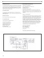
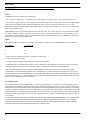
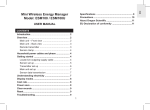
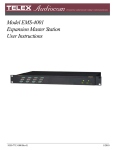
FIGURE 1.
ii
TW System Concept Block Diagram
CHAPTER 1
Introduction
DESCRIPTION
The Model SPK300L, a Portable Speaker User Station, is a component used in the TW INTERCOM SYSTEM. Each User
Station is a communications unit along a multi-unit conference bus.
Figure 1, “TW System Concept Block Diagram,” on page ii, shows User Station interconnection, and User Station connection
to the system power supply.
User Station interconnection can be: 1) centrally wired, with each cable coming from a central point, or 2) distributed, where
all the user stations are looped together from one to another, or 3) a combination of both. The centrally wired interconnection
not only reduces interchannel crosstalk, but also allows for easier expansion into an assignable channel, multi-channel system.
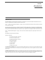
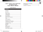
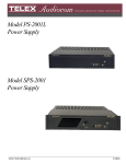
Figure 1, “SPK300L Block Diagram,” on page 3, shows user station functional components, input/output connections, and
controls.
The SPK300L User Station has the following
functional components:
•a microphone preamplifier with limiter
•an electronic microphone switch
•a "bilateral current source" line driver
•a listen volume control
•a headphone amplifier
•a speaker amplifier
•a speaker switch
•a channel selector switch
The Microphone Preamplifier/limiter converts the small microphone signal to a strong line level signal conditions the signal
strength from loud and soft talkers to be almost the same sends the signal to the line via the microphone switch and a "bilateral
current source".
The Bilateral Current Source adds signal, via the channel select switch, to the line without affecting any signals already on
the line. The bilateral current source also extracts the listen signal from the line and sends it to the headphone amplifier via the
volume control. Some of the user's own voice signal ("sidetone") is also fed to the headphone amplifier.
1
Introduction
The Channel Selector Switch selects the channel on which the user will talk and listen. The headphone amplifier output
drives the user's headphones.
The Volume Control also feeds the speaker amplifier via the speaker switch and the speaker dim network.
The User Station Voltage Regulator takes power from channel 1, regardless of the channel selector switch setting (exception:
local power option units). The regulator not only supplies regulated power to the user station, but also prevents unwanted
interaction between the user station and the intercom line which is supplying the power. Because the regulator takes power
from channel 1, channel 2 can be expanded into many channels by using a switch and, for each channel, a separate wire and a
termination network consisting of a 200 ohm resistor and a 10 microfarad capacitor in series. (See the Application Diagrams in
the TW Intercom Systems Technical Manual).
A TW System Power Supply terminates a line with 200 ohms.
Operational Controls
The SPK300L User Station has the following controls, described and shown in Section 3:
•Channel Select Switch
•Latching-action Microphone ON-OFF toggle switch.
•Momentary-action Microphone ON-OFF pushbutton switch.
•Speaker/Headphone Volume Control
•Call Switch /indicator
•Speaker ON/OFF switch
•Sidetone Adjustment
Connection, Inputs and Outputs
The SPK300L User Station has four input/output connectors:
•Dynamic Microphone type headset or handset
•Carbon Microphone type headset or handset
•Line Input (ties the station to the intercom line
•Loop/extension (allows another station to access the line through the first station. Also called loop-through.
2
Specifications
FIGURE 1.
SPK300L Block Diagram
Specifications
OPERATING DISTANCES
Audio Line
Voltage
1 volt, peak (0 dBm voltage-equivalent)
Average
Speech Level
Range
-20 dBV to -10 dBV
Absolute
Maximum
Speech Level
3 volts, peak (linear limit)
Audio Line
Impedance,
Nominal
200 50 ohms, 75 Hz to 20 kHz
System will continue to operate from 50 ohms to 300
ohms.
Maximum DC
limit
5,000 ft distance along cable, power supply to single
station #22 gauge wire - DC voltage drop limitation.
Maximum AC
limit
10,000 ft. dry pair, power supply at each end, #22 gauge
wire
System
Capacitance
0.3 microgarads (cumulative effect of 10,000 ft. of
maximum cable at 30 picofarads/foot)
USER STATIONS SPECIFICATIONS
Input DC
voltage
20 to 35 volts DC, operating from -200 to +36 volts DC
without damage.
DC Current
Quiescent, 10 to 40 milliamps
50 milliamps, typical (w/25 ohms headphones)
75 milliamps, typical (w/25 ohms headphones + lights)
100 milliamps, typical (w/8 ohm speaker)
Impedance
Across Line
10,000 ohms typical; 2,000 ohms worst case dynamic
operation
Ambient
Temperature
Range
Operating 0° C to 60° C (0° F to 140° F)
Storage -55° C to 125° C (-67° F to 257° F)
Noise
Contribution
to 200 ohm
Line
One unit: -75 dBu
Ten unit: -67 dBu
Imput
Impedance *
470 ohms
Source
Impedance*
200 ohms, nominal
Maximum
Input Level
150 millivolts
Voltage Gain
54 dB
Frequency
Response
100 Hz to 10,000 Hz, 3 dB
SYSTEM DC CURRENT
Nominal
32 volts DC
Operational
Range
18 to 35 volts DC
Steady state
without
damage
-1.5 volts to 36 volts DC
Transient
200 volts, 8 milliseconds or less (after this time, power
supply and user station fuses will open).
System DC
Current
MICROPHONE PREAMPLIFIER
Quiescent
(per station)
10 to 40 milliamps
Dynamic (per
station)
50 milliamps (w/25 ohm headphones)
70 milliamps (w/25 ohm headphones and lights)
100 milliamps (w/8 ohm speaker)
Start-Up
Current
1.25 amperes, 50 units, all kinds
Fault Current
4.0 amperes, power supply at voltage >12 volts
1.0 amperes, power supply at voltage <12 volts
3
Introduction
Limiter Range
50 dB
Carbon Mic
Excitation
Current
10 milliamps, nominal
CURRENT SOURCE
Transfer Ratio
5 milliamps/1.5 volts
Output
5 milliamps into 200 ohms
Overall
Voltage Gain
24 dB
Overall
Voltage Gain
9 volts peak-to-peak into 25 ohms
Output Power
Headset Station: 1/2 watt into 25 ohms
Speaker Station: 2 watts into 8 ohms
Frequency
Response
150 Hz to 8000 Hz, 3 dB
Headphone
Impedance
Range
25 to 600 ohms
Sidetone
Adjustment
Range
20 dB to full ON
Signaling
Frequency
20,000 kHz 3dB
Flashing Rate
3Hz 2 Hz
HEADPHONE AMPLIFIER
CALL LIGHT
DIMENSION
3.468” H x 1.5” W x 3.0” D (13.21 x 3.81 x 7.62 centimeters)
4
CHAPTER 2
INSTALLATION
MECHANICAL INSTALLATION
The Model SPK300L Portable Speaker User Station is 4.0 inches (101.6 mm) high X 8.0 inches (203.2 mm) wide X 8.0 inches
(203.2 mm) deep. Additional depth should be allowed for the rear panel XLR-type line connectors. When installing this unit,
allow space for control access, cabling and servicing. Provide space for: cabling service loops, reaching XLR-type connector
lock releases, and headset connector/cables. If the headset connector is remotely located, allow space between this cable and
interference sources such as video/TV monitors, power supplies and equipment with internal power supplies. There are no
ventilation requirements.
Headset Requirements
Dynamic microphone headset type:
•50 to 1000 ohm microphone
•25 to 1000 ohm headphone(s)
High efficiency headphones are recommended because less line current is required from the power supply. Use headphones
with an impedance of 25 ohms or greater. Low impedance 8 ohm headphones are not recommended. Headphones with good
acoustic isolation (20 to 40dB) improve communication in high ambient noise environments, and allow the user to use the
headphones at a less tiring, lower volume.
In the headset connecting cable, prevent coupling between the microphone and headphone leads by using a shielded, twisted
pair for the microphone, and a separate, twisted pair for the headphones. Do not allow headphone ground to contact microphone ground or shield. Tie the shield to microphone ground or "mic low". The headset cable can be made longer when the
microphone and headphone pairs are physically separated. The wider the separation, the longer the cable length which may be
used. Estimated maximum usable headphone cable lengths are as follows:
Single cable,
Two shielded twisted pair
10 ft. (3 m).
Dual ribbed cable,
Two shielded twisted pair:
30 ft. (9 m).
5
INSTALLATION
ELECTRICAL
Power
The SPK300L receives electrical power from either:
(1) a system power supply (26 to 32 volts DC on line connector pins 2 (+) and 1 (com) (1 or two channel operation); or
(2) a local power supply option (14 to 26 volts DC). A user station requires 18 to 33 volts to be a 10,000 ohm bridging impedance across the powering line, but the station can otherwise operate (as in the local power option) from 12 to 33 volts.
When using a local power supply option, each channel requires a 200 ohm load. See Figure 1-1. It is necessary to do this only
once for each channel string.
Model SPK300L current requirements range from 30 to 100 mA; Since, in (1), above, the power and communications signals
may share conductors, it may be necessary to overcome power losses by increasing conductor size over long runs (over 1/2
mile (804 m)). Typical operating distance for one SPK300L station is 1/2 mile (.80 km), and for one SPK300L, 1/3 mile (0.53
km) using a normal # 22 AWG conductor size.
Signal
The required number of conductors to interconnect user stations is as follows (For standard unbalanced TW user stations):
# of Channels
# of Conductors
1
2*
1
3 **
2
3 ***
*Using a TW power supply (and possibly operating on a TW system).
**Using a non-TW power supply.
***Using a TW power supply and operating on a TW two channel system.
Use shielded cable to interconnect user stations in areas of possible electrical interference, (areas such as those near: digital
equipment, high current primary power conductors ("mains"), transformers, transmitters, and lamp dimmers).
Most two channel applications may use either standard microphone cable (for convenience) or two-twisted-pair cable
(considerably less expensive than microphone cable). Standard wire size for the TW Intercom System is #22 gauge wire for
interconnection. For permanent installations it is recommended that each channel should have individually shielded twisted
pair of at least #22 gauge wire, such as Belden #8723 for 2 channels. Connect the shield to system common but do not tie the
shield to chassis, earth or connector shell ground.
Crosstalk Control
In the TW Intercom System all channels share a common circuit ground return. Crosstalk due to common ground resistance
can be lowered by reducing the common ground resistance. Reduction of ground resistance can occur as a side benefit of using
shielded cable, since the shield drains can be tied together and electrically parallel the circuit ground. Another way of lowering
resistive crosstalk is to "homerun" all interconnecting cables to a central or "home" location. In this configuration, the ground
path is short and the corresponding ground resistance is small. Crosstalk due to mutual capacitance occurs when the signal on
one wire of a twisted pair couples into the other wire. Separating the two conductors with a shield greatly reduces the capacitive crosstalk.
To reduce both capacitive and resistive crosstalk and to afford a degree of RF and electrostatic shielding, use a cable which has
a shielded twisted pair for each channel. Each pair consists of a conductor for the channel, a conductor for circuit ground
return and a shield around the two conductors. The shield is accessed via a drain conductor. This drain conductor and the
shield can augment the circuit grounds and thus lower the ground resistance.
6
USER STATION CONNECTIONS
Routing the TW Intercom System cables along the same
ductways and pathways as power cabling can increase the
noise and hum levels.
Moisture / Contamination Protection
When using equipment in the rain, always protect the equipment with plastic covers----also, make sure all cable connectors are lifted out of the mud or snow and protected with
plastic bags. Water, mud and snow in connectors can cause
considerable audible noise.
Pin 3 - Channel 2
XLR-4-31/32 types (for three-Channels)
Pin 1 - Channel 1
Pin 2 - Channel 2
Pin 3 - Channel 3
Pin 4 - Common (low side of line)
Hum Prevention
Prevent inducing hum into the system by not locating user
stations near hum sources such as power transformers, electrical switch panels, lamp dimmers or TV cameras. When the
microphone switch is turned on, the dynamic microphone
acts as a sensitive antenna for hum sources.
USER STATION CONNECTIONS
Dynamic Microphone headset connector:
XLR-4-31 type receptacle (J1)
Input level: -55 dbu nominal
Output level to headphone: 10 volts peak-to-peak open
circuit.
Pin 1 - Microphone low
Pin 2 - Microphone high
Pin 3 - Headphone low
Pin 4 - Headphone high
Carbon Microphone headset connector:
Standard 1/4" Phone Jack (J2)
Input level: -15 dbu nominal
Output to Headphone: 10 volts peak-to-peak open circuit.
Tip - Carbon Microphone
Ring - Headphone
Sleeve - Common/ground
Line input connectors: (J3/J4)
XLR-3-31/32 types (for two-channels)
Pin 1 - Common (low side of line)
Pin 2 - Channel 1
7
INSTALLATION
8
CHAPTER 3
OPERATION
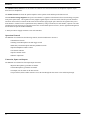
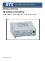
Operating Controls
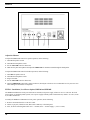
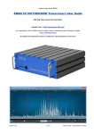
The table below lists the Model SPK300L operating controls. The reference numbers in the table correspond to the circled
numbers in Figure 3-1.
TABLE 1. Model
SPK300L Operating Controls
REF NO.
NAME
DESCRIPTION
1
Channel Select Switch
Selects one of two channels (standard) or one of three channels (optional). The Call
Light Option transmitter and receiver operate on the channel selected by this switch.
The Channel Select Switch is omitted in the Single Channel (SC) option.
2
Mic ON/OFF Toggle
A latching action switch. Turning ON the microphone slightly “dims” or attenuates
the speaker.
3
Mic ON/OFF Pushbutton
A momentary action pushbutton switch. Not standard with the Call Light Option.
Turning ON the microphone here also slightly “dims” or attenuates the speaker.
4
Volume
A speaker / headphone volume control. May be dual control for the Duel Listen (DL)
or Program (E) Option.
CAUTION: Always turn this control all the way couter-clockwise (to the left)
before plugging in the headset.
5
Call Light Indicator
This switch / indicator appears only on the user stations with the Switch “Call
Light” option. When depressed, this switch adds a 20 kilohertz signal to the TW
intercom line on the same channel that the Channel Select Switch has been set. This
signal activates the Call Light Receiver on all user stations which are switched to the
same channel.
This switch:
6
Speaker ON / OFF
1. turns the speaker on
2. disables the headset microphone
3. enables the panel
7
Sidetone
The screwdriver adjusted SIDETONE control sets the “sidetone” level during
headset operation and sets the “balance” nulling during speaker / panel microphone
operation.
9
OPERATION
6
FIGURE 1.
2
1
4
7
3
&
5
SPK300L Reference View
Adjust the Sidetone
To adjust the SIDETONE control for speaker operation, do the following:
1.
Turn ON the speaker switch.
2.
Turn ON the microphone switch.
3.
Set the VOLUME control to about 50%
4.
Hum into the panel microphone and adjust the SIDETONE for minimum sound through the loudspeaker.
To adjust the SIDETONE control for headset operation, do the following:
1.
Turn OFF the speaker switch.
2.
Turn ON the microphone switch.
3.
Plug in a headset.
4.
Set the VOLUME control to about 50%.
5.
Turn the SIDETONE control fully counter-clockwise, then adjust it clockwise for a comfortable level of your own voice
while talking into the headset. microphone.
EN5541 - Installation, Local Power Option, RMS300 and SPK300L
The RMS300 and SPK 300 can be powered from an external (local) power supply of between 18 to 33 volts DC. the local
power option, as supplied by RTS Systems, uses a power supply assembly (RTS # 9020-4425-00), which is 117 VAC, 60 Hz
in, 24 VDC 400 mA out.
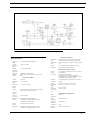
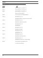
To modify the RMS300 or SPK300L for local power operation, do the following:
1.
Remove diode D26 from the CC300 P.C. board.
2.
Add J6, 4-pin jack (Calrad #30-454, RTS # 2013-0005-00), to the back panel.
3.
Wire, as shown in the diagram below. Pin 1 = common, Pin 2 = external supply + (18 to 33 VDC).
10
Operating Controls
4.
Wire PG, 4-pin plug (Calrad #30-453, RTS # 2013-0016-00) to the external supply: Pin 1 = common,
Pin 2 = external supply +.
5.
Plug P6 into J6 on the RMS300 or SPK300L back panel.
NOTE: If using RTS local power option kit 9002-5541-00, the external supply will already be wired to P6. Obsolete products
have been discontinued and are no longer available for purchase.
4
1
3
2
J6
Local Power
(Back Panel)
#22 AWG Wire
Remove D26
CC 300 P.C. Board
FIGURE 2.
CC300 P.C. Board modifications.
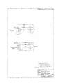
When a system is constructed using locally powered user stations, it is essential that all channels are terminated with a 200
ohm system termination. System terminations (see diagram below) include:
An RTS System TW power supply *
• A discrete 200 ohm resistor for each locally supplied channel
• When application of a D.C. voltage is expected or possible, a 10 microfarad / 50 Volt capacitor in series with the 200 ohm
resistor for each locally supplied channel.
FIGURE 3.
Power Supply diagram
*Examples of RTS System power supplies are:
PS8, PS10, PS15, PS20, PS30, PS31, PS50, and PS60.
11
OPERATION
12
CHAPTER 4
DRAWINGS
13
DRAWINGS
Model SPK300L
Number
TitleS
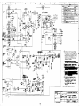
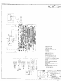
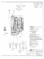
D2712
Schematic Diagram, CC300, page 1 of 3
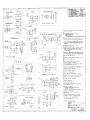
SD2712
Schematic Diagram, CC300, page 2 of 3
SD2712
Schematic Diagram, CC300, page 3 of 3
Wiring for External Microphones
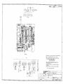
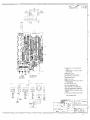
SD3585
Servicing Diagram, Model RMS300/SPK300L,
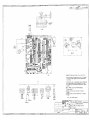
WD2712
Wiring Diagram, pg. 1 of 7
SPK/RMS300 Standard -L Option and Local Power Option
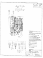
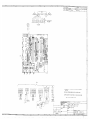
WD2712
Wiring Diagram, pg. 2 of 7
SPK/RMS300 3CH and 3CH-L Options
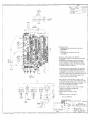
WD2712
Wiring Diagram, pg. 3 of 7
SPK/RMS300-DL
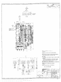
WD2712
Wiring Diagram, pg. 4 of 7
SPK/RMS300, FB Option
WD2712
Wiring Diagram, pg. 5 of 7
SPK/RMS300-DL-3CH
WD2712
Wiring Diagram, pg. 6 of 7
SPK/RMS300 Program Input Option
WD2712
Wiring Diagram, pg. 7 of 7
SPK/RMS300 DL (Dual Listen) - E (Program Input)
SD3487
Servicing Diagram, Light Signaling Circuit
CC-28, Phase III configuration
14