1
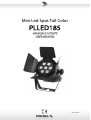
Mini Led Spot Full Color
PLLED185
MANUALE UTENTE
USER MANUAL
1
Rev. 02-03/12
Indice
1. Introduzione
4
1.1 Contenuto della confezione
1.2 Istruzioni per l'apertura dell'imballo
1.3 Alimentazione
1.4 Istruzioni di sicurezza
2. Introduzione
4
4
4
4
5
2.1 Caratteristiche
2.2 Canali DMX
5
5
3. Setup
5
3.1 Sostituzione fusibile
3.2 Collegamento di più apparecchi
3.3 Conversione tra un connettore 3 poli e 5 poli
3.4 Creazione di una catena DMX
3.5 Collegamento Master / Slave
3.6 Installazione
4. Istruzioni operative
5
5
6
6
6
6
7
4.1 Pannello di controllo
4.2 Menu
4.3 Configurazione
4.4 Canali DMX
7
7
9
9
5. Caratteristiche tecniche
9
2
Table of contents
1. Preface
10
1.1 Packing list
1.2 Unpacking instructions
1.3 AC Power
1.4 Safety instructions
10
10
10
10
2. Introduction
11
2.1 Features
2.2 DMX channel
11
11
3. Setup
11
3.1 Fuse replacement
3.2 Fixture linking
3.3 3-Pin to 5-Pin conversion chart
3.4 Setting up a DMX serial data link
3.5 Master/Slave fixture linking
3.6 Orientation
11
11
12
12
12
12
4. Operating instructions
13
4.1 Navigating the control panel
4.2 Menu map
4.3 User configurations
4.4 DMX channel values
13
13
15
15
5. Technical specifications
15
3
1. Introduzione
1.1 Contenuto della confezione
Proiettore
Alimentazione
Manuale d’uso
1
1
1
1.2 Istruzioni per l’apertura dell’imballo
Appena ricevuto il prodotto, rimuovere l’imballo e controllare il contenuto assicurandosi
che tutto sia presente all’interno e che sia in buone condizioni.
Informare il venditore o il corriere se alcune parti sono danneggiate o se il cartone
presenta segni di manomissione. Non buttare l’imballo in caso si debba rispedire il
prodotto, per evitare che a causa di un imballo non idoneo il prodotto possa danneggiarsi
durante il trasporto.
1.3 Alimentazione
Per individuare la corretta tensione di alimentazione controllare le indicazioni stampate
sul pannello posteriore o far riferimento alle caratteristiche tecniche.
L’apparecchio deve essere collegato direttamente alla rete o attraverso un interruttore
ON/OFF; mai attraverso un variatore di tensione (es. dimmer), anche se esso soddisfa le
caratteristiche di alimentazione del proiettore.
Verificare inoltre la corretta alimentazione di rete.
Attenzione! Verificare la corretta alimentazione di rete per il proiettore.
Se la tensione di rete non rispetta quella indicate, possono verificarsi danni
all’apparecchio.
Il proiettore deve essere collegato ad un appropriato circuito di terra.
1.4 Istruzioni di sicurezza
Leggere attentamente il presente manuale. Esso include informazioni importanti
riguardo l’installazione, l’uso e la manutenzione di questo prodotto.
Assicurarsi che la tensione di rete sia la stessa di quanto indicato sul prodotto.
Non utilizzare il proiettore se il cavo di alimentazione è danneggiato o tagliato.
Non rimuovere o tagliare il collegamento di terra. Esso è utilizzato per ridurre i rischi di
scossa elettrica.
Scollegare dalla rete elettrica prima di effettuare qualsiasi operazione (es connessione
DMX).
Non rimuovere i coperchi in nessun caso. All’interno non ci sono elementi su cui fare
manutenzione.
Non utilizzare mai il proiettore se i coperchi sono rimossi.
Non collegare mai questo apparecchio ad un’unità dimmer.
Assicurare al proiettore un’adeguata ventilazione.
Garantire uno spazio di almeno 15 cm tra il proiettore e qualsiasi altra superficie.
Non utilizzare il proiettore se presenta segni di danneggianento.
Durante lunghi periodi di non utilizzo disconnettere il proiettore dalla rete elettrica.
Installare il prodotto sempre su una superficie o sostegno sicuri.
I cavi di alimentazione devono essere disposti in modo che non possano essere
calpestati o schiacciati da oggetti posti sopra o contro, prestando particolare attenzione
4
al punto di uscita dall'apparecchio.
Il proiettore va pulito secondo le indicazioni riportate dal costruttore (vedere il capitolo
Pulizia).
Il proiettore deve essere posizionato lontano da qualsiasi sorgente di calore, incluso gli
amplificatori.
L’apparecchio deve essere riparato da personale qualificato nei casi in cui:
A. il cavo di alimentazione o la spina siano danneggiati
B. oggetti solidi e soprattutto liquidi siano caduti sopra o all’interno del proiettore
C. il proiettore sia stato esposto a pioggia o acqua
D. il proiettore non sembra funzionare in condizioni normali o manifesta un evidente calo
di prestazioni.
2. Introduzione
2.1 Caratteristiche
Multi color
Strobo colori
Dimmer 0-100%
Controllo DMX-512
Microfono interno
Master / Slave
Modalità multi canale
2.2 Canali DMX
Canale
Funzione
1
2
3
4
5
6
7
8
DIMMER
ROSSO
VERDE
BLU
SEQUENZA 7 COLORI
DISSOLVENZA COLORI
STROBO
MODALITA’ MUSICALE
3. Set up
Disconnettere l’alimentazione prima di sostituire il fusibile. Rimpiazzare sempre
con un fusibile dalle stesse caratteristiche.
Alimentazione: prima di collegare l’apparecchio assicurarsi che l’alimentazione del luogo
sia adeguata a quanto riportato sull’apparecchio.
3.1 Sostituzione fusibile
Con un cacciavite piatto rimuovere il fusibile danneggiato e rimpiazzarlo con uno
identico. Inserire il nuovo fusibile e riconnettere l’alimentazione.
3.2 Collegamento di più apparecchi
E’ necessario un collegamento di tipo DMX per utilizzare uno o più proiettori in uno show,
5
attraverso un controller DMX o un semplice collegamento master / slave.
A seconda del numero di canali o del canale DMX assegnato, è possibile calcolare il
numero massimo di proiettori collegabili.
La lunghezza massima della catena DMX non deve superare i 500 m.
Il numero massimo di proiettori raccomandati in ogni catena è 32.
Per collegare più apparecchi in catena, bisogna avere a disposizione dei cavi DMX, se si
preferisce creare da soli tali cavi, utilizzare un adeguato cavo schermato da interferenze
elettromagnetiche
3.3 Conversione tra un connettore 3 poli e 5 poli
Utilizzando un controller DMX con uscita 5 poli è necessario un adattatore da 5 a 3 poli.
Nella figura seguente sono indicati i collegamenti
Collegamento DMX
Femmina DMX (vista posteriore)
Maschio DMX (vista posteriore)
1- Terra
2- Segnale (-)
3- Segnale (+)
4- Non connesso
5- Non connesso
3.4 Creazione di una catena DMX
collegare il primo proiettore al controller DMX, collegare i proiettori successivi in catena
come indicato nella figura.
3.5 Collegamento Master/Slave
1. Connettere il connettore maschio a tre poli all'uscita femmina a tre poli
sull'apparecchio
2. Connettere la terminazione del cavo femmina a tre poli all'ingresso dell'apparecchio
successivo (connettore maschio). Procedere allo stesso modo con gli apparecchi
successivi.
3.6 Installazione
questo apparecchio può essere installato in qualsiasi posizione purché sia garantita
un'adeguata ventilazione della stanza.
6
4. Istruzioni operative
4.1 Pannello di controllo
Accedere alle funzioni del pannello di controllo utilizzando i quattro pulsanti posti sotto al
display.
Quando è selezionata una funzione nel menù il display visualizzerà immediatamente la
prima opzione disponibile. per selezionare premere <ENTER>.
Premere il pulsante <MENU> ripetutamente fino a raggiungere la funzione desiderata.
Utilizzare i pulsanti <UP> e <DOWN> per navigare all'interno delle opzioni del menù.
Premere <ENTER> per selezionare la funzione del menù visualizzata o per abilitare le
opzioni di menù. Per tornare al menù precedente senza effettuare cambiamenti, premere
il pulsante <MENU>.
4.2 Menù
per ottimizzare le performance di questo prodotto leggere attentamente il presente
manuale per familiarizzare con i comandi principali dell'apparecchio. Queste istruzioni
contengono importanti informazioni di sicurezza riguardo l'uso e la manutenzione del
proiettore. Si raccomanda di tenere il manuale insieme all'apparecchio per eventuali usi
futuri.
7
(Menu principale)
|_____________ (1° livello)
(2° livello)
|_____________
Add (Indirizzo DMX)
|_____________ A.001
|_____________ ……
|_____________ A.512
FLAS (Impostazioni strobo)
|_____________ Frgb (regolazione della velocità strobo)
|_____________
F0XX
|_____________
FrXX (Regolazione intensità rosso)
|_____________
FgXX (Regolazione intensità verde)
|_____________
FbXX (Regolazione intensità blu)
FL0- (regolazione tempo dissolvenza)
|_____________ F0XX
CHAS (regolazione tempo cambio colori)
|_____________ C0XX
SOUN (Modalità musicale)
|_____________ SOU1 (modalità musicale strobo)
|_____________
S1XX
|_____________ SOU2 (modalità musicale cambio colori modo 1)
|_____________
S2XX
|_____________ SOU3 (modalità musicale cambio colori modo 2)
|_____________
S3XX
Lrgb (regolazione intensità R, G, B)
|_____________ LrXX (Regolazione intensità rosso)
|_____________ LgXX (Regolazione intensità verde)
|_____________ LbXX (Regolazione intensità blu)
SLA- (modalità Master o Slave)
|_____________ SL00 slave
|_____________ SL01 master
8
4.3 Configurazione
Indirizzamento DMX
1. Premere il pulsante <MENU> finché non compare la scritta Addr, quindi premere
<ENTER>
2. Verranno visualizzati dei numeri che rappresentano l'indirizzo attuale. Premere <UP>
e <DOWN> fino a raggiungere l'indirizzo desiderato.
3. Premere <ENTER> per confermare.
SLA modalità MASTER / SLAVE:
1.SL00 modalità slave
2.SL01 modalità master
SOUN modalità musicale:
1. SOU1 modalità musicale strobo (da 1 a 10)
2. SOU2 modalità musicale cambio colori (da 1 a 10)
ecc.
Modalità DMX
Questa modalità permette di controllare il proiettore attraverso un controller DMX.
La modalità standard di funzionamento dell'apparecchio è DMX.
4.4 Canali DMX
Canale
1
2
3
4
5
6
7
8
Valore
0 - 255
0 - 255
0 - 255
0 - 255
0 - 255
0 - 255
0 - 255
0 - 255
5. Dati tecnici
MODEL
Alimentazione
Potenza assorbita:
LED
Peso
Dimensioni
Funzione
Dimmer
Rosso
Verde
Blu
Sequenza 7 colori + velocità (da 105 a 255)
Dissolvenza colori
Strobo
Modalità musicale
PLLED185
110V- 240V / 50-60Hz
25W
7 x 3W RGB full color
3,5Kg
230(H) x 230(W) x 450(L) mm
9
1. Preface
1.1 Packing list
Par Light
Power-line
User Manual
1 pcs
1 base
1pcs
1.2 Unpacking instructions
On receiving a fixture, carefully unpack the carton, check the contents to ensure that all
parts are presented, and have been received in a good condition. Notify the shipper
immediately and retain packing material for inspection if any parts appear damaged from
shipping or the carton itself shows, sign of mishandling. Save the carton and all packing
materials. In the event that a fixture must be returned to the factory , it is important that
the fixture be returned in the original factory box and packing.
1.3 AC Power
To determine the power requirements for a particular fixture, see the label affixed to the
back plate of the fixture or refer to the fixtures specifications chart. A fixture listed current
rating is its average current draw under normal conditions. All fixtures must be directly
powered off a switched circuit and cannot be run off a rheostat (variable resistor) or
dimmer circuit, even if the rheostat or dimmer source voltage matches the fixtures
requirement. Check the fixture or device carefully to make sure that if a voltage selection
switch exists that it sets to the correct line voltage you will use.
Warning! Verify that the voltage select switch on your unit matches the line
voltage applied. Damage to your fixture may result if the line voltage applied
does not match the voltage indicated on the voltage selector switch. All fixtures
must be connected to circuits with a suitable Earth ground.
1.4 Safety instructions
Please read these instructions, it includes important information about the
installation, usage and maintenance of this product.
Be sure that the local power outlet match that of the required voltage for your unit.
Do not attempt to operate this unit if the power cord has been frayed or broken. Do not
attempt to remove or break off the ground prong from the electrical cord. This prong is
used to reduce the risk of electrical shock and fire in case of an internal short.
Disconnect from main power before making any type of connection.
Do not remove the cover under any conditions. There are no user serviceable parts
inside.
Never operate this unit when it's cover is removed.
Never plug this unit in to a dimmer pack.
Always be sure to mount this unit in an area that will allow proper ventilation.
Allow about 6 inch (15cm) between this device and a wall.
Do not attempt to operate this unit, if it becomes damaged.
During long periods of non-use, disconnect the unit's main power.
Always mount this unit in safe and stable matter.
Power-supply cords should be routed so that they are not likely to be walked on or
pinched by items placed upon or against them, paying particular attention to the point
they exit from the unit.
10
Cleaning -The fixture should be cleaned only as recommended by the manufacturer. See
Cleaning for details.
Heat -The appliance should be situated away from heat sources such as radiators, heat
registers, stoves, or other appliances (including amplifiers) that produce heat.
The fixture should be serviced by qualified service personnel when:
A. The power-supply cord or the plug has been damaged.
B. Objects have fallen, or liquid has been spilling to the appliance.
C. The appliance has been exposed to rain or water.
D. The appliance does not appear to operate normally or exhibits a marked change in
performance.
2. Introduction
2.1 Features
Multi-Colors
Color Strobe
Electronic Dimming 0-100%
Built in Microphone
DMX-512 Control
Auto/Master & Slave synchronization
Multi-channel mode
Dip switch to choose menu
2.2 DMX Channel
Channel
Function
1
2
3
4
5
6
7
8
DIMMER
RED
GREEN
BLUE
7 COLOR CHANGES
COLOR SHADE
STROBE
SOUND ACTIVATED
3. Set up
Disconnect the power cord before replacing a fuse and always replace with the
same type fuse.
Power Supply: Before plugging your unit in, be sure the source voltage in your area
matches the required voltage for your fixture.
3.1 Fuse replacement
With a flat head screwdriver wedge the fuse hold out of its housing. Remove the
damaged fuse from its holder and replace with exact same type fuse. Insert the fuse
holder back in its place and reconnect power.
3.2 Fixture linking
You will need a serial data link to run light show of one or more fixtures using a DMX-512
11
controller or to run synchronized on two or more fixtures set to a master/slave operating
mode. The combined number of channels required by all the fixtures on a serial data link
determines the number of fixtures the data link can support.
Maximum recommended serial data link distance:500 meters(1640ft).
Maximum recommended number of fixtures on a serial data link:32 fixtures.
Data cabling
To link fixtures together you must obtain data cables. If you choose to create your own
cable please use data-grade cables that can carry a high quality signal and are less
prone to electromagnetic interference.
3.3 3-Pin to 5-Pin conversion chart
Note! If you use a controller with a 5 pin DMX output connector. you will need to use a
5pin to 3 pin adapter.
The chart below details a proper cable conversion:
3.4 Setting up a DMX serial data link
at first link the first light and DMX control through XLR-connection signal cable, then
connect the light in series as the follow
3.5 Master/Slave fixture linking
1.Connect the (male) 3 pin connector side of the DMX cable to the output (female)3pin
connector of the first fixture.2.Connect the end of the cable coming from the first fixture
which will have a (female)3 pin connector to the input connector of the next fixture
consisting of a (male) 3 pin connector. Then, proceed to connect from the output as
stated above to the input of the following fixture and so on.
3.6 orientation
This fixture may be mounted in any position provided there is adequate room for
ventilation.
12
4. Operating instructions
4.1 Navigating the control panel
Access control panel functions using the four panel buttons located directly under the
Display.
When a menu function is selected, the display will show immediately the first available
option for the selected menu function. To select a menu item, press<ENTER>.
Press the <MENU> button repeatedly until you reach the desired menu function. Use the
<UP> and <DOWN> buttons to navigate the menu options. Press the <ENTER> button
to select the menu function currently displayed, or to enable a menu option. To return to
the previous option or menu without changing the value, press the <MENU> button.
4.2 Menu map
To optimize the performance of this product, please read these operating instructions
carefully to familiarize you with the basic operations of this unit. These instructions
contain important safety information regarding the use and maintenance of this unit.
Please keep this manual with the unit, for future reference.
13
(Main menu)
st
|_____________ (1 class option)
|_____________
(2rd class option)
Add (Address code setting)
|_____________ A.001
|_____________ ……
|_____________ A.512
FLAS (Strobe setting)
|_____________ Frgb(the total speed of strobe to be adjusted)
|_____________
F0XX
|_____________
FrXX (To adjust red brightness seperately)
|_____________
FgXX (To adjust green brightness seperately)
|_____________
FbXX (To adjust blue brightness seperately)
FL0- (the interval time of adjusting the color shade)
|_____________ F0XX
CHAS (the interval time of adjusting the color change)
|_____________ C0XX
SOUN (Sound control)
|_____________ SOU1 (sound control of strobe)
|_____________
S1XX
|_____________ SOU2 (sound control of color change mode 1)
|_____________
S2XX
|_____________ SOU3 (sound control of color change mode 2)
|_____________
S3XX
Lrgb (Adjust separately r,g,b Led brightness)
|_____________ LrXX (To adjust red brightness seperately)
|_____________ LgXX (To adjust green brightness seperately)
|_____________ LbXX (To adjust blue brightness seperately)
SLA- (Set master or slave)
|_____________ SL00 slave
|_____________ SL01 master
14
4.3 User configurations
Addr-DMX Address Setting via control board
1. Tap the MENU button until Addr is displayed, press ENTER.
2. X will now be displayed, X represents the displayed address. Press the UP or DOWN
buttons to find your desired address.
3. Press ENTER to confirm, and then press and hold the MENU button for at least three
seconds to assign.
SLA Master-Slave online mode:
1. SL00: slave mode
2. SL01: master mode
SOUN Soundactive:
1. SOU1: sound control of strobe
2. SOU2: sound control of color change
Etc.
DMX mode
This mode allows the unit to be controlled by any universal DMX controller.
The default mode for the fixture is DMX, as follows
4.4 DMX channel values
Channel
1
2
3
4
5
6
7
8
Value
0 - 255
0 - 255
0 - 255
0 - 255
0 - 255
0 - 255
0 - 255
0 - 255
5. Technical data
Model
Voltage
Power consumption:
LED
Weight
Dimensions
Function
Dimmer
Red
Green
Blue
7 color change + speed (from 105 to 255)
Color shade
Strobe
Sound activated
PLLED185
110V- 240V / 50-60Hz
25W
7 x 3W RGB full color
3,5Kgs
230(H) x 230(W) x 450(L) mm
15
Proel S.p.A.
Via alla Ruenia 37/43
64027 Sant'Omero (TE) ITALY
Tel. +39 0861 81241
Fax. +39 0861 887862
Mail: [email protected]
Web: www.proel.com
16