1
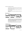
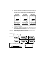
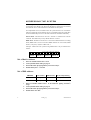
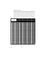
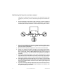
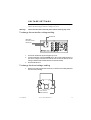
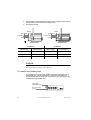
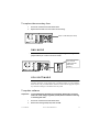
P/N 35000050, Rev. B. © 1996 - 1999 Martin Professional A/S, Denmark
RoboColor III
user manu al
INTRODUCTION
Congratulations on your choice of the RoboColor III system, designed and
manufactured by Martin Professional. The RoboColor III is a high performance,
automated color changing system, providing exciting possibilities for lighting
designers in many applications. The rugged construction combined with the
choice of high quality components ensures that your RoboColor III system will
perform reliably for many years to come.
SAFETY PRECAUTIONS
The RoboColor III is NOT for domestic use.
• Read user manual before use.
• For protection against dangerous electric shock, always ground (earth) the system
electrically, use only a source of AC power that complies with local building and
electrical codes, and do not expose the system to rain or moisture.
• Disconnect the system from AC power before removing any cover or part.
• Disconnect the system from AC power if the lamp blows. Allow the heads to cool
for 15 minutes before installing a new lamp.
• Do not illuminate surfaces within 30 cm (12 inches) of the heads.
• Do not place filters or other objects over the lenses.
• Keep all combustible materials (for example fabric, wood, paper) at least 30 cm
(12 inches) away from the heads. Keep flammable materials well away from the
heads.
• Provide a minimum clearance of 10 cm (4 inches) around the fans and air vents.
• Do not operate the system if the ambient temperature exceeds 40° C (104° F).
• When suspending the system above ground level, verify that the structure can
hold at least 10 times the weight of all installed devices, and secure the fixtures
with approved safety cables. Block access below the work area whenever
installing or removing the system.
• For protection against dangerous UV radiation, never operate the system with
missing and/or damaged covers or lenses, and do not stare into the light. Replace
any broken or cracked component immediately.
• Refer all service to a qualified technician.
2
Introduction
RoboColor III
SETTING U P
The RoboColor III system consists of the RoboColor III heads, which are the
color changing spotlights, and the RoboColor III controller, which drives the
heads. You can connect up to four heads to one controller.
Important!
Do NOT connect RoboColor III heads directly to the mains supply.
Connect them only to a RoboColor III controller.
UNPACKING
The RoboColor III system includes the following items:
•
•
•
•
•
•
RoboColor III heads with Martin 150 W Metal Halide discharge lamps
Mounting bracket
Fittings for mounting bracket (two lever handles and two metal washers)
RoboColor III controller
5 meter XLR-XLR cable
User manual
PREPARING HEADS
Secure the mount ing bracket
•
The mounting bracket is already fitted onto the head. Secure it with the two
metal washers and lever handles supplied.
First, fit the metal
washer.
Then, secure
the lever handle.
User Manual
Setting Up
3
Check volt age set t ing
Important!
The voltage setting of the heads must match your local AC mains
supply.
The RoboColor III head is supplied in a 50 Hz or 60 Hz version. It is not possible
to rewire from 50 Hz to 60 Hz, or vice versa.
•
The factory setting is printed on a label on the back of the head. Check the
setting against the table below and rewire if necessary, following the
instructions on page 15.
50 Hz Model
60 Hz Model
Mains supply
Ballast tapping
Mains supply
Ballast tapping
210V - 235V
230V
200V - 215V
210V
235V - 245V
240V
215V - 225V
220V
245V - 255V
250V
225V - 235V
230V
PREPARING THE CONTROLLER
Inst al l a mains pl ug
Warning!
For protection from dangerous electric shock, the fixture must
be grounded (earthed). The AC mains supply shall be have a
fuse or circuit breaker, and ground-fault protection.
The controller may be supplied without a plug on the mains cable. You will have
to fit a plug that conforms to your local mains outlet before you can connect the
unit to AC power. The double insulated mains cable contains three wires.
4
1
Connect the BROWN wire to the LIVE pin.
2
Connect the BLUE wire to the NEUTRAL pin.
3
Connect the YELLOW/GREEN wire to the EARTH pin.
Wire
Pin
Marking
Screw color (US)
brown
live
“L”
yellow or brass
blue
neutral
“N”
yellow/green
ground
Setting Up
silver
green
RoboColor III
Check volt age sett ing
Important!
The controller’s voltage setting must match your local mains supply.
The factory setting is printed on a label on the back of the controller. Check the
setting against the table below and rewire if necessary, following the instructions
on page 15.
Mains Supply
Transformer Setting
210 - 240V
230V
240 - 255V
250V
CONNECTING THE SYSTEM
You can use any DMX or Martin lighting controller to operate the RoboColor III
system. Control data is transmitted from the lighting controller via XLR data
cables to the data input on the RoboColor III controller. The RoboColor III
controller’s data output sends the data further to additional units: up to 32
RoboColor III systems can be connected on the same data link.
The RoboColor III can also be operated without a lighting controller in standalone mode. In this mode, the system runs built-in sequences that are
automatically or music triggered depending on the mode selected. A special
master/slave feature allows several RoboColor III systems to synchronize (via the
data link) in stand-alone mode. These features are further described later.
Connect the RoboColor I II cont roller to t he heads
The motor and lamp cables of each head must be connected to the RoboColor III
controller. Connect each pair of cables to sockets of the same group (1, 2, 3 or 4)
on the RoboColor III controller as shown below.
Important!
User Manual
To avoid damaging the controller, make sure that it is disconnected
from AC power before connecting the heads.
Setting Up
5
Connect the lighting cont roller
Once all heads have been connected to the RoboColor III controller, connect the
RoboColor III controller to the lighting controller. The procedure is the same for a
Martin RS-485 or DMX 512 controller, but you may need a 5-to-3-pin adapter
cable if using a DMX 512 controller.
1
Connect the data output on your lighting controller to the data input on the
RoboColor III controller.
MARTIN CONTROLLER: Use the XLR-XLR or DSUB-XLR cable supplied with
the controller.
Martin Lighting Controller
with 3 pin XLR output.
3 pin XLR male:
Pin 1: GND (screen)
Pin 2: Signal (+)
Pin 3: Signal (-)
3 pin XLR female:
Pin 1: GND (screen)
Pin 2: Signal (+)
Pin 3: Signal (-)
RoboColor III Controller
with 3 pin XLR in and output.
DMX CONTROLLER: Most DMX controllers have 5-pin XLR sockets for data
output. Use a 5-pin to 3-pin phase-reversing adaptor, such as P/N 11820003,
as shown below. This adaptor connects pin 2 on one end to pin 3 on the other
end, and vice versa, to correct the difference in polarity between the
RoboColor III system and the DMX controller.
Note: The RoboColor III controller also has an option to swap the XLR pin
connections, making phase-reversing cables unnecessary. See page 18.
DMX Lighting Controller
with standard 5 pin XLR output.
5 pin XLR male:
Pin 1: GND (screen)
Pin 2: Signal (-)
Pin 3: Signal (+)
Pin 4: N/C
Pin 5: N/C
6
3 pin XLR female:
Pin 1: GND (screen)
Pin 2: Signal (+)
Pin 3: Signal (-)
RoboColor III Controller
with 3 pin XLR in and output.
Setting Up
RoboColor III
2
Connect the data output of the first RoboColor III controller to the data input
of the next device. Use the XLR-XLR cable supplied when connecting to
another RoboColor III controller or fixture with Martin polarity (pin 3 cold).
Use a phase-reversing cable when connecting to a DMX device (pin 3 hot).
3-pin to 3-pin
Phase-Reversing
Cable
3-pin to 5-pin
Phase-Reversing
Cable
Connections
Connections
5-pin to 3-pin
Phase-Reversing
Cable
Connections
Male
Female
Male
Female
Male
Female
1
2
3
1
2
3
1
2
3
1
2
3
4
5
1
2
3
4
5
1
2
3
P/N 11820006
P/N 11820002
P/N 11820003
3
Continue the link this way, connecting output to input (daisy-chaining), until
all units are linked together.
4
Finally, insert a male XLR termination plug in the output socket of the last
Ω resistor between pin 2
unit on the link. Use a 3 pin XLR male plug with a 120Ω
and 3 (supplied with all Martin controllers).
Important!
Failure to use a termination plug can cause communication errors
between the lighting controller and the units.
Lighting controller
RoboColor III controllers
Use 3 pin XLR/XLR data cables to connect
the units. Pin 1 = screen, pin 2 = signal (+),
pin 3 = signal (-).
User Manual
Setting Up
Insert a termination
plug in the last unit
on the data link.
7
ADDRESSING THE SYSTEM
When using the RoboColor III with a lighting controller, you must set the DIPswitch to the start channel, also known as the address, which is the first channel
the controller uses to send instructions to the RoboColor III system.
For independent control, each RoboColor III system must have its own address
and non-overlapping control channels. If two or more RoboColor III systems have
the same address they will receive the same instructions and behave identically.
Martin mode: The RoboColor III uses 1 channel to communicate with the
controller. The address may be any channel between 1 and 32.
DMX mode: The RoboColor III uses 5 consecutive DMX channels in tracking
mode (DMX mode 1) and 6 consecutive DMX channels in vector mode (DMX
mode 2). The factory default is DMX mode 1.
1
2
3
4
5
6
7
8
9
10
11
12
13
14
15
16
17
18
19
20
Example: 4 RoboColor III systems using DMX mode 1 may be addressed as
follows:
System 1
System 2
Address: 1 Address: 6
System 3
Address: 11
System 4
Address: 16
Set a Mart in address
1
Select an available address from 1 to 32.
2
Look up the DIP-switch setting on page 9.
3
Set the DIP-switch by flipping ON the pins found in step 2.
4
Set DIP-switch pins 7 - 10 to OFF.
Set a DMX address
DMX Mode
Color Control
DMX Channels
PL113 Jumper Setting
1
Tracking
5 Channels
No Jumper
Tracking/Vector
6 Channels
Pin 1 and 2
2
8
default
1
Select an available address from 1 to 507 within the lighting controller’s
range.
2
Look up the DIP-switch setting on page 9.
3
Set the DIP-switch by flipping ON the pins found in step 2.
4
Set DIP-switch 10 to OFF.
Setting Up
RoboColor III
DIP-SWITCH TABLE
This table shows DIP-switch settings for channels 1- 511. To find a setting, locate
the channel in the table. Follow the row to the left to find the settings for pins 1
through 5; follow the column to the top to find the settings for pins 6 through 9. A
“0” indicates the pin is turned off and a “1” indicates the pin is turned on. Pin 10
is always switched OFF when using the RoboColor III with a lighting controller.
Example: The table shows the setting for channel 212 is 00101 for pins 1 - 5 and
0110 for pins 6 - 9. Pins 3, 5, 7, and 8 are set to on; pins 1, 2, 4, 6, 9, and 10 are
set to off.
',306ZLWFK#6HWWLQJ
&4
3
4
3
4
3
4
3
4
3
4
3
4
3
4
3
4
3
4
3
4
3
4
3
4
3
4
3
4
3
4
3
4
3# #2))
4# #21
&5 &6 &7
3 3 3
3 3 3
4 3 3
4 3 3
3 4 3
3 4 3
4 4 3
4 4 3
3 3 4
3 3 4
4 3 4
4 3 4
3 4 4
3 4 4
4 4 4
4 4 4
3 3 3
3 3 3
4 3 3
4 3 3
3 4 3
3 4 3
4 4 3
4 4 3
3 3 4
3 3 4
4 3 4
4 3 4
3 4 4
3 4 4
4 4 4
4 4 4
User Manual
&8
3
3
3
3
3
3
3
3
3
3
3
3
3
3
3
3
4
4
4
4
4
4
4
4
4
4
4
4
4
4
4
4
&<
&;
&:
&9
3
3
3
3
3
3
3
4
3
3
4
3
3
3
4
4
3
4
3
3
3
4
3
4
3
4
4
3
3
4
4
4
4
3
3
3
4
3
3
4
4
3
4
3
4
3
4
4
4
4
3
3
4
4
3
4
4
4
4
3
4
4
4
4
4
5
6
7
8
9
:
;
<
43
44
45
46
47
48
49
4:
4;
4<
53
54
55
56
57
58
59
5:
5;
5<
63
64
65
66
67
68
69
6:
6;
6<
73
74
75
76
77
78
79
7:
7;
7<
83
84
85
86
87
88
89
8:
8;
8<
93
94
95
96
97
98
99
9:
9;
9<
:3
:4
:5
:6
:7
:8
:9
::
:;
:<
;3
;4
;5
;6
;7
;8
;9
;:
;;
;<
<3
<4
<5
<6
<7
<8
<9
<:
<;
<<
433
434
435
436
437
438
439
43:
43;
43<
443
444
445
446
447
448
449
44:
44;
44<
453
454
455
456
457
458
459
45:
45;
45<
463
464
465
466
467
468
469
46:
46;
46<
473
474
475
476
477
478
479
47:
47;
47<
483
484
485
486
487
488
489
48:
48;
48<
493
494
495
496
497
498
499
49:
49;
49<
4:3
4:4
4:5
4:6
4:7
4:8
4:9
4::
4:;
4:<
4;3
4;4
4;5
4;6
4;7
4;8
4;9
4;:
4;;
4;<
4<3
4<4
4<5
4<6
4<7
4<8
4<9
4<:
4<;
4<<
533
534
535
536
537
538
539
53:
53;
53<
543
544
545
546
547
548
549
54:
54;
54<
553
554
555
556
557
558
559
55:
55;
55<
563
564
565
566
567
568
569
56:
56;
56<
573
574
575
576
577
578
579
57:
57;
57<
583
584
585
586
587
588
589
58:
58;
58<
593
594
595
596
597
598
599
59:
59;
59<
5:3
5:4
5:5
5:6
5:7
5:8
5:9
5::
5:;
5:<
5;3
5;4
5;5
5;6
5;7
5;8
5;9
5;:
5;;
5;<
5<3
5<4
5<5
5<6
5<7
5<8
5<9
5<:
5<;
5<<
633
634
635
636
637
638
639
63:
63;
63<
643
644
645
646
647
648
649
64:
64;
64<
653
654
655
656
657
658
659
65:
65;
65<
663
664
665
666
667
668
669
66:
66;
66<
673
674
675
676
677
678
679
67:
67;
67<
683
684
685
686
687
688
689
68:
68;
68<
693
694
695
696
697
698
699
69:
69;
69<
6:3
6:4
6:5
6:6
6:7
6:8
6:9
6::
6:;
6:<
6;3
6;4
6;5
6;6
6;7
6;8
6;9
6;:
6;;
6;<
6<3
6<4
6<5
6<6
6<7
6<8
6<9
6<:
6<;
6<<
733
734
735
736
737
738
739
73:
73;
73<
743
744
745
746
747
748
749
74:
74;
74<
753
754
755
756
757
758
759
75:
75;
75<
763
764
765
766
767
768
769
76:
76;
76<
773
774
775
776
777
778
779
77:
77;
77<
783
784
785
786
787
788
789
78:
78;
78<
793
794
795
796
797
798
799
79:
79;
79<
7:3
7:4
7:5
7:6
7:7
7:8
7:9
7::
7:;
7:<
7;3
7;4
7;5
7;6
7;7
7;8
7;9
7;:
7;;
7;<
7<3
7<4
7<5
7<6
7<7
7<8
7<9
7<:
7<;
7<<
833
834
835
836
837
838
839
83:
83;
83<
843
844
Setting Up
9
SWITCHING ON
Having connected and addressed all units, you may now start operating these
from the lighting controller. The RoboColor III controller does not have a power
switch, hence the unit is switched ON when mains power is applied.
N O T E : After switching on, the RoboColor III controller defaults to autodetection mode in order to determine whether a Martin RS-485 or DMX 512
controller is connected. To ensure correct protocol auto-detection, switch the
lighting controller on before switching on the RoboColor III controller.
If you are using a Martin controller then please refer to the controller’s manual for
further instructions. If you are using a DMX 512 controller then please refer to the
DMX 512 protocol listed in appendix A. All remotely controllable functions are
briefly described starting on page 11.
MASTER/SLAVE OPERATION
Master/slave stand-alone operation means that you can have one RoboColor III
system (master system) acting as a controller when set to stand-alone mode.
Additional systems (slave systems), which all need to have DIP-switch setting 1
(i.e. switch 1 = ON), can then be connected as if the master system were a normal
lighting controller. All RoboColor III system will then perform the same
programs fully synchronized. To ensure error free communication between the
master and the slave systems you will have to insert a female XLR termination
plug (120Ω) in the free input socket of the master system and a male XLR
termination plug (120Ω) in the free output socket of the last slave system on the
data link.
See page 20 for stand-alone DIP-switch settings.
Important!
Set one, and only one, RoboColor III system to stand-alone mode,
otherwise damage may occur to the units.
FOCUS
When the heads are in their final positions and powered on, you can adjust the
focus objective to achieve a sharp beam.
10
Setting Up
RoboColor III
CONTROLLABLE F UNCTIONS
This section briefly describes the various functions that can be remotely
controlled via the serial data input on the RoboColor III system.
BLACKOUT
The default position of the color wheel is the blackout position. This means that
no light is emitted from the unit until the wheel is moved from this position.
COLORS
Each RoboColor III head has 11 dichroic colors plus white, all placed on a color
wheel. You can select these colors individually on any of the heads.
COLOR SPLIT EFFECTS
By placing the color wheel between two adjacent colors, color split effects can be
achieved.
COLOR SCROLLING
When switching from one color to another you can reduce the speed to emphasize
the scrolling effect.
COLOR STROBE
Strobe between two adjacent colors is achieved by first selecting a color and then
activating the strobe. The color wheel will then strobe between the color selected
and the next color on the wheel. E.G. to make a black/white strobe, select the
blackout position on the color wheel and activate the strobe. You can adjust the
strobe rate to a desired frequency.
STAND-ALONE
The built-in stand-alone programs can be activated from the controller.
User Manual
Controllable Functions
11
SERVICE
AND
MAINTENANCE
GENERAL MAINTENANCE
Warning!
Disconnect the system from AC power before removing any
cover.
To ensure optimum performance from the RoboColor III system, it is important to
keep the heads clean. Dirty lenses and filters reduce the brightness and diffuse the
beam. A fan blocked by dust may provoke overheating and cause the thermostat
to cut out the lamp intermittently. Thanks to the mechanical construction of the
RoboColor III, maintenance and cleaning can be done easily and requires no
special tools.
The RoboColor III controller should not require any maintenance.
Clean the opt ics
1
To access the optical components
inside head, remove the screws as
shown and then lift and remove
the bottom cover.
2
Use only a clean, soft and lint-free
cloth to clean the color filters. You
may need to wet the cloth in a nonaggressive glass cleaning liquid if
the filters are greasy. Use th e
same cl oth to cl ean the focus
objective.
Remove the 4 screws.
Clean the cooling fan
Then lift and remove the cover.
•
12
For adequate cooling of the
head, the fan must be free of
dust. Clean the fan if the air
flow seams to be reduced.
The fan is located at the top of
the unit as per the following
figure. It is easiest to clean
the fan using compressed air.
Service and Maintenance
Use compressed air
to clean the fan.
RoboColor III
LAMP REPLACEMENT
Warning!
Disconnect the fixture from AC power before removing any cover.
To reduce the risk of the lamp shattering, never exceed the average lamp life,
listed below, by more than 25%. Disconnect the system from AC power if the
lamp blows. Allow the heads to cool for 15 minutes before installing a new lamp.
The RoboColor III comes with the Martin 150 W Metal Halide lamp installed.
The Osram HTI 150 and GE CSS 150 may be used as well. Installing any other
lamp may damage the fixture.
Martin 150 W
Metal Halide
P/N
Osram HTI 150
GE CSS 150
97010107
97010108
97010104
Average Life
2000 h
750 h
1000 h
Color Temp.
5000K
6500K
5000K
Output
900 lm
1200 lm
900 lm
To change the lamp
1
Remove the 3 thumbscrews that
secure the access plate of the lamp
socket assembly at the rear of the
head and withdraw the lamp socket
assembly.
2
Remove the old lamp from the
socket.
Remove
screws.
3
Holding the new lamp in a clean cloth
(do not touch the glass), carefully
insert it firmly and squarely into the
lamp socket.
Withdraw lamp socket assembly.
4
If your fingers touch the glass, clean the bulb with a clean, lint-free cloth
wetted with alcohol.
5
Replace the lamp-socket assembly and tighten the thumbscrews.
Do not touch the
glass
Hold only by the
ceramic base.
User Manual
Service and Maintenance
13
Opti mizing the lamp f or maximum output
The lamps are adjusted at the factory, however, fine adjustment of the lamp
assembly may be necessary to achieve maximum light output and a minimum hotspot.
14
1
The lamp housing access plate is held in place by 3 screws. Another 3
screws, shown below, are used to adjust the lamp-holder. Turning these
clockwise pulls the lamp towards the rear of the lamp housing and vice versa.
2
Select the 'Lamp Adjustment' DIP-switch setting by switching ON DIP-switch
number 8 and 10, and apply power to the system. After finishing the reset the
heads will produce white beams.
3
Move the head so the spot is projected on a flat surface. Focus the beam.
4
If there is an off-center “hot spot,” the lamp is not centered in the reflector.
Pull the hot spot into the center of the field with small adjustments of one or
more of the screws. Note: the Martin Metal Halide lamp is nearly as large as
the reflector opening - very little side to side adjustment is possible or
necessary.
5
If the light is significantly brighter in the center of the field than it is at the
edge, the lamp is too far forward in the reflector. Pull the lamp in by turning all
three screws clockwise 1/4-turn at a time until the light is evenly distributed.
6
If the light is brighter around the edge than it is in the center, or if light output
is low, the lamp is too far back in the reflector. “Push” the lamp out by turning
the screws counterclockwise 1/4-turn at a time until the light is bright and
evenly distributed.
7
If you have made large sideways adjustments, disconnect the fixture from AC
power, allow it to cool, and remove the lamp assembly to ensure that the lamp
is still placed squarely in the socket.
Service and Maintenance
RoboColor III
VOLTAGE SETTINGS
It is essential that the voltage and frequency setting of your RoboColor III system
matches the mains supply. Otherwise damage may occur.
Warning!
Disconnect the fixture from AC power before removing any cover.
To change the controller vol tage sett ing
Transformer
NEUTRAL.
Do NOT remove
BLUE wire.
230V
250V
1
Access the transformer by removing the top cover.
2
On the transformer, move the BROWN wire to the correct voltage terminal. If
the mains voltage is between 210 and 240 volt use the 230 volt tap. If the
voltage is between 240 and 255 volt then use the 250 volt tap.
3
Re-assemble the unit.
To change the head vol tage sett ing
1
Remove 6 screws from the back of the unit, as shown, and carefully withdraw
the entire rear assembly.
First, remove
these 6 screws.
User Manual
Service and Maintenance
15
2
On the ballast, move the BLACK wire to the correct voltage terminal. Use the
following table to select the correct voltage setting.
3
Re-assemble the unit.
Ballast
Ballast
230V/50Hz
210V/60Hz
240V/50Hz
220V/60Hz
250V/50Hz
230V/60Hz
60 Hz Version
50 Hz Version
50 Hz Model
60 Hz Model
Mains supply
Ballast tapping
Mains supply
Ballast tapping
210V - 235V
230V
200V - 215V
210V
235V - 245V
240V
215V - 225V
220V
245V - 255V
250V
225V - 235V
230V
FUSES
Should the RoboColor III system cease to work it may be due to a blown fuse.
This section describes how to replace the fuses.
To replace the pri mary fuse
•
The primary fuse is located inside the IEC mains input socket at the rear of
the controller. Use a small screwdriver to pry open the fuse holder and
replace the fuse with one of the same size and rating. The fuse rating is also
printed on the serial number label.
Mains fuse
6.3AT/250V (slow
IEC mains input
socket.
16
Service and Maintenance
RoboColor III
To replace the secondary f use
1
Access the circuit board as described earlier.
2
Replace the fuse with one of the same size and rating.
F202, 3.15AT/250V (slow blow)
DMX MODE
•
You can switch between DMX modes 1 and 2 by setting or removing the
jumper between pin 1 and 2 on PL113 as shown.
PL113
1
Set jumper between
pin 1 and 2 to
enable extended
DMX mode
(mode 2).
CPU SOFTWARE
The RoboColor III control software can be updated when new features become
available. Software can be supplied by your Martin dealer as P/N 62122026.
Please check with your Martin dealer to find out if the software upgrade requires
any mechanical changes to the RoboColor III system.
To update sof tware
Important!
To avoid damaging the CPU by electrostatic discharges, touch the
heat sink of the voltage regulator (IC102) before and when removing
or inserting the CPU.
1
Access the circuit board as described earlier.
2
Remove the existing CPU (IC101) from the PCB.
User Manual
Service and Maintenance
17
3
Place the new CPU in the IC socket, ensuring that all pins enter the socket
correctly, and that the CPU is correctly oriented. Then press it firmly into the
socket.
Heat sink of IC102.
CPU (IC101).
XLR PIN-OUT
If the RoboColor III is operated via a DMX controller, you can change the XLR
pin-out to eliminate the need for phase-reversing cables. This can be done inside
the RoboColor III controller by moving two jumpers as shown below.
Reversed:
- 3
2 +
Pin 2 = Pin 3 = +
Non-Reversed
- 3
2 +
Pin 2 = +
Pin 3 = -
Jumpers for swapping
+ and - signals on
data in and output.
18
Service and Maintenance
RoboColor III
DMX PROTOCOL
DMX channel
Mode 1
Mode 2
1
2-5
(Head 1 - 4)
-
User Manual
6
Value
Function
0 - 74
75 - 138
139 - 170
171 - 202
203 - 255
Strobe, Stand-Alone, Reset
No function
Strobe on (Fast Æ Slow)
Remote Stand-alone auto-trigger
Remote Stand-alone music-trigger
Reset
0 - 15
16 - 30
31- 45
46 - 60
61 - 75
76 - 90
91 - 105
106 - 120
121 - 135
136 - 150
151 - 165
166 - 180
Color Wheel (Head 1, 2, 3, 4)
Blackout Æ White
White Æ Color 1
Color 1 Æ Color 2
Color 2 Æ Color 3
Color 3 Æ Color 4
Color 4 Æ Color 5
Color 5 Æ Color 6
Color 6 Æ Color 7
Color 7 Æ Color 8
Color 8 Æ Color 9
Color 9 Æ Color 10
Color 10 Æ Color 11
181 - 184
185 - 189
190 - 194
195 - 199
200 - 204
205 - 209
210 - 214
215 - 219
220 - 224
225 - 229
230 - 234
235 - 239
240 - 255
Color Wheel “Snaps” (Head 1 - 4)
Color 11
Color 10
Color 9
Color 8
Color 7
Color 6
Color 5
Color 4
Color 3
Color 2
Color 1
White
Blackout
0
1 - 255
Color Speed
Tracking
Speed (fast Æ slow)
DMX Protocol
19
STAND-ALONE SEQUENCES
The following table provides a description of the stand-alone sequences selectable
via the DIP-switch.
DIP-Switches ON
Step
All
Protocol auto-detect (DMX512 / Martin RS-485)
2, 10
Stand Alone Sequence - Auto-trigger
1, 2, 10
Stand Alone Sequence - Music-trigger
2, 3, 10
Stand Alone Sequence - Auto-trigger (Head 1 - 4 same color)
1, 2, 3, 10
Stand Alone Sequence - Music-trigger (Head 1 - 4 same color)
8, 10
Lamp Adjust (color = white)
(1), 5, 10
Adjustment sequence #1
Toggle DIP-switch #1 to
advance through sequence.
1
Color Adjust Position #1
2
Color Adjust Position #2
4, 10
LED Chase - Auto-trigger
1, 4, 10
LED Chase - Music-trigger
20
Description
Stand-alone Sequences
RoboColor III
TROUBLESHOOTING
Problem
Probable cause(s)
Suggested remedy
None of the RoboColor IIIs
respond to the lighting
controller.
The lighting controller is
disconnected from the data link.
Connect the lighting controller.
Use of incorrect cable between
the controller and the first
RoboColor III system on the
data link.
If using a DMX controller with
standard 5-pin output socket,
remember to use a 5 to 3-pin
adapter cable that swaps pin 2
and 3, between the lighting
controller and the first
RoboColor III system on the
data link.
Bad data link connection.
Check connections/cables in the
data link and correct
accordingly.
Data link not terminated with
termination plug.
Insert termination plug in the
last unit on the data link.
Incorrectly addressing (DIPswitch setting) of the RoboColor
III controller.
Ensure that all lights are
addressed in compliance with
the lighting controller
configuration.
One or more RoboColor III
controllers are set to stand-alone
mode, thus transmitting on the
link.
Set the DIP-switch on the
RoboColor III controller to the
correct address.
There is no power to the
RoboColor IIIs.
Apply power.
The RoboColor III controllers
have failed in the protocol autodetection.
Switch off the RoboColor III
controllers and then back on
again. In general, switch on the
lighting controller before the
RoboColor III controllers.
One of the units on the link is
defective and disturbs data
transmission.
By-pass one unit at a time until
normal operation is regained.
Do this by unplugging the XLR
in and out connectors and then
connect them directly together.
One or more of the RoboColor
IIIs does not respond to the
lighting controller or responds
erratically.
User Manual
Troubleshooting
21
Problem
Probable cause(s)
Suggested remedy
No light emission from some or
all RoboColor III heads.
The lamp is on but the color
wheel is on blackout position.
Change color via lighting
controller.
No lamp inserted.
Insert lamp.
Malfunctioning lamp.
Replace lamp.
No lamp strike due to too low
mains
voltage.
Measure mains voltage and
check against ballast and
transformer tappings. Correct
tappings if necessary.
Head cables not connected to
RoboColor III controller.
Connect cables. Remember to
switch off the RoboColor III
controller first.
The RoboColor III system
appears to be completely dead
(no reset when switching on).
Mains fuse blown.
Replace mains fuse.
PCB fuse(s) blown.
Replace PCB fuse(s).
Lamp is cutting out
intermittently.
Ambient temperature is too
high.
Reduce room temperature.
Fan speed is reduced due to fan
covered by dirt and dust.
Clean fan.
Incorrect ballast and transformer
tappings.
Measure mains voltage and
check against ballast and
transformer tappings. Correct
tappings if necessary.
22
Troubleshooting
RoboColor III
SPECIFICATIONS
ELECTRICAL DATA (SYSTEM WITH 4 HEADS)
• Power consumption: .....................................................................................680 W
• Current consumption: ......................................................... 3.7 A @ 230 V / 50Hz
• Power factor:.......................................................................................................0.8
COMPATIBLE LAMPS
• Martin 150 W Metal Halide............................................................. P/N 97010107
• Osram HTI 150 ................................................................................ P/N 97010108
• GE CSS 150..................................................................................... P/N 97010104
PHOTOMETRIC DATA
• Beam angle (standard): ...................................................................................... 17°
• Beam angle (optional): ...................................................................................... 25°
THERMAL DATA
• Max ambient temperature: ............................................................................ 40° C
MECHANICAL DATA
• Weight (single RoboColor III head): ................................................... 6 kg (13 lb)
208 m m
8.2 "
267 m m
1 0.5"
1 65 m m
6 .5"
∅11 m m
1 90 m m
7.5"
3 00m m
11.8 "
User Manual
Specifications
23
0DUWLQ#3URIHVVLRQDO#$26
Olof Palmes Allé 18
8200 Aarhus N Denmark
www.martin.dk
Tel.: +45 8740 0000