1
Digi Connect® Family and
ConnectPort™ TS Family
User’s Guide
Digi Connect Family Products:
Digi Connect SP
Digi Connect Wi-SP
Digi Connect ME
Digi Connect ME 4 MB
Digi Connect Wi-ME
Digi Connect EM
Digi Connect Wi-EM
Digi Connect ES 4/8 SB
Digi Connect ES 4/8 SB with Switch
Digi ConnectPort TS Products:
ConnectPort TS 4x4
ConnectPort TS 4x2
ConnectPort TS W
ConnectPort TS 8
ConnectPort TS 8 MEI
ConnectPort TS 16
90000565_L
©Digi International Inc. 2010. All Rights Reserved.
The Digi logo, Digi Connect, iDigi, ConnectPort, Digi SureLink, Digi Dialserv NetSilicon,
NET+Works, NET+OS, NET+, are trademarks or registered trademarks of Digi International, Inc.
All other trademarks mentioned in this document are the property of their respective owners.
Information in this document is subject to change without notice and does not represent a
commitment on the part of Digi International.
Digi provides this document “as is,” without warranty of any kind, either expressed or implied,
including, but not limited to, the implied warranties of fitness or merchantability for a particular
purpose. Digi may make improvements and/or changes in this manual or in the product(s) and/or
the program(s) described in this manual at any time.
This product could include technical inaccuracies or typographical errors. Changes are periodically
made to the information herein; these changes may be incorporated in new editions of the
publication.
2
Contents
Contents........................................................................................................................................................................................3
About this guide...........................................................................................................................................................................7
Purpose ................................................................................................................................................................................7
Audience..............................................................................................................................................................................7
Scope ...................................................................................................................................................................................7
Where to find more information..........................................................................................................................................7
Digi contact information .....................................................................................................................................................8
Chapter 1: Introduction............................................................................................................................................................9
Important Safety Information ..............................................................................................................................................9
The Digi Connect Family ..................................................................................................................................................10
Digi Connect SP™ ..................................................................................................................................................10
Digi Connect Wi-SP™............................................................................................................................................10
Digi Connect ME™.................................................................................................................................................10
Digi Connect Wi-ME™ ..........................................................................................................................................11
Digi Connect EM™.................................................................................................................................................11
Digi Connect Wi-EM™ ..........................................................................................................................................12
Digi Connect™ ES 4/8 SB and Digi Connect 4/8 SB with Switch ........................................................................12
Digi ConnectPort™ TS products ............................................................................................................................13
Digi ConnectPort TS 4x4 products .........................................................................................................................13
Features .............................................................................................................................................................................14
User interfaces.........................................................................................................................................................14
Quick reference for configuring features ................................................................................................................15
Hardware features ...................................................................................................................................................20
Network interface features ......................................................................................................................................20
Configurable network services................................................................................................................................20
IP protocol support ..................................................................................................................................................21
RealPort software ....................................................................................................................................................25
Alarms .....................................................................................................................................................................25
Modem emulation ...................................................................................................................................................25
Security features in Digi devices.............................................................................................................................26
Configuration management .....................................................................................................................................27
Customization capabilities ......................................................................................................................................27
Supported connections and data paths in Digi devices .....................................................................................................28
Network services .....................................................................................................................................................28
Network/serial clients..............................................................................................................................................30
Interfaces for configuring, monitoring, and administering Digi devices ..........................................................................31
Configuration capabilities .......................................................................................................................................31
3
Configuration interfaces ..........................................................................................................................................31
Monitoring capabilities and interfaces ....................................................................................................................40
Device administration .............................................................................................................................................41
Chapter 2: Hardware installation..........................................................................................................................................42
Rack mounting (ConnectPort TS 16 only) ........................................................................................................................43
Installation ...............................................................................................................................................................43
Safety and installation considerations .....................................................................................................................44
Chapter 3: Configure Digi devices.........................................................................................................................................45
Default IP address and methods for assigning an IP address ............................................................................................46
Assign an IP address using the Digi Device Setup Wizard.....................................................................................47
Configure an IP address using DHCP .....................................................................................................................48
Configure an IP address using Auto-IP...................................................................................................................48
Configure an IP address from the command-line interface.....................................................................................49
IP addresses and the iDigi Platform ........................................................................................................................49
Test the IP address configuration ............................................................................................................................49
Configuration through the iDigi Platform .........................................................................................................................50
Create an Account on iDigi.com .............................................................................................................................50
Add the Digi device to the idigi.com Device List...................................................................................................51
iDigi Platform views for configuring and managing Digi devices .........................................................................53
Configuration through the Digi Device Setup Wizard ......................................................................................................56
Discover the device .................................................................................................................................................56
Network settings......................................................................................................................................................56
Port profiles .............................................................................................................................................................56
Verify configuration settings...................................................................................................................................57
Save settings ............................................................................................................................................................57
Finish the wizard and select next action..................................................................................................................57
To further configure the Digi device.......................................................................................................................57
Configuration through the web interface...........................................................................................................................58
Open the web interface............................................................................................................................................58
Organization of the web interface ...........................................................................................................................60
Change the IP address from the web interface, as needed ......................................................................................63
Network configuration settings ...............................................................................................................................64
Serial port settings ...................................................................................................................................................84
GPIO pins ................................................................................................................................................................93
Alarms .....................................................................................................................................................................95
System settings ........................................................................................................................................................99
Remote management settings................................................................................................................................105
User settings ..........................................................................................................................................................110
Applications ..........................................................................................................................................................116
Alternative configuration options for Digi Connect Wi-SP ............................................................................................123
4
Configuration through the Java applet interface .............................................................................................................126
Accessing the Java applet interface.......................................................................................................................126
Differences between web and Java applet interfaces ............................................................................................126
System requirements .............................................................................................................................................126
The Home page .....................................................................................................................................................127
Network settings....................................................................................................................................................129
Serial ports.............................................................................................................................................................129
GPIO pins ..............................................................................................................................................................129
Alarms ...................................................................................................................................................................130
Security features ....................................................................................................................................................130
Configuration through the command line .......................................................................................................................131
Access the command line ......................................................................................................................................131
Verify device support of commands .....................................................................................................................131
Configuration through Simple Network Management Protocol (SNMP).......................................................................134
Batch capabilities for configuring multiple devices........................................................................................................134
Chapter 4: Monitor and manage Digi devices ....................................................................................................................135
Monitoring capabilities from the iDigi Platform.............................................................................................................136
Monitoring capabilities in the web and Java applet interfaces........................................................................................137
Display system information ..................................................................................................................................137
Manage connections and services .........................................................................................................................145
Monitoring capabilities from the command line .............................................................................................................146
Commands for displaying device information and statistics ................................................................................146
Commands for managing connections and sessions .............................................................................................148
Monitoring Capabilities from SNMP ..............................................................................................................................149
Chapter 5: Digi device administration ................................................................................................................................150
Administration from the web interface ...........................................................................................................................150
File management ...................................................................................................................................................151
X.509 Certificate/Key Management .....................................................................................................................152
Backup/restore device configurations ...................................................................................................................155
Update firmware and Boot/POST Code................................................................................................................155
Restore a device configuration to factory defaults................................................................................................156
Display system information ..................................................................................................................................159
Activate Find Me LED ..........................................................................................................................................159
Reboot the Digi device ..........................................................................................................................................159
Enable/disable access to network services ............................................................................................................159
Administration from the Java applet interface ................................................................................................................160
Backup/restore device configurations ...................................................................................................................160
Restore device configuration to factory defaults...................................................................................................160
Display system information ..................................................................................................................................161
Reboot the Digi device ..........................................................................................................................................161
5
Enable/disable access to network services ............................................................................................................161
Administration from the command-line interface ...........................................................................................................162
Chapter 6: Latency Tuning ..................................................................................................................................................163
What is Latency? .............................................................................................................................................................163
Recommended Process for Deterministic Ethernet/IP Performance...............................................................................163
Best-case scenario for achieving deterministic Ethernet/IP networking behavior................................................163
Step 1: Determine the characteristics of your application...............................................................................................164
Step 2: Determine the latency budget and type of latency ..............................................................................................164
Step 3: Optimize the physical layer.................................................................................................................................164
Step 4: Optimize the network and transport layers .........................................................................................................165
Command options for optimizing network and transport layers...........................................................................166
Considerations for using latency-related command options .................................................................................167
Step 5: Optimize the application layer ............................................................................................................................167
Chapter 7: Specifications and certifications .......................................................................................................................168
Hardware specifications ..................................................................................................................................................169
See hardware references for some Connect Family product specifications..........................................................169
Digi Connect ES specifications.............................................................................................................................169
ConnectPort TS 8 specifications ...........................................................................................................................170
ConnectPort TS 16 specifications .........................................................................................................................171
ConnectPort TS 4x4 and ConnectPort TS 4x2 specifications...............................................................................172
Wireless networking features ..........................................................................................................................................173
Regulatory information and certifications.......................................................................................................................175
RF exposure statement ..........................................................................................................................................175
FCC certifications and regulatory information (USA only)..................................................................................175
Industry Canada (IC) certifications .......................................................................................................................176
.International EMC (Electromagnetic Emissions/Immunity/Safety) standards ....................................................177
Chapter 8: Troubleshooting .................................................................................................................................................178
Troubleshooting Resources .............................................................................................................................................178
System status LEDs.........................................................................................................................................................179
Digi Connect Family LEDs...................................................................................................................................179
ConnectPort TS Family Products ..........................................................................................................................186
Glossary ....................................................................................................................................................................................194
6
About this guide
Purpose
This guide describes and shows how to configure, monitor, and administer Digi devices.
Audience
This guide is intended for those responsible for setting up Digi devices. It assumes some
familiarity with networking concepts and protocols. A glossary is provided with definitions for
networking terms and features discussed in the content.
Scope
This guide focuses on configuration, monitoring, and administration of Digi devices. It does not
cover hardware details beyond a certain level, application development, or customization of Digi
devices.
Where to find more information
In addition to this guide, find additional product and feature information in the these documents:
Online help and tutorials in the web interface for the Digi device
Digi Connect Hardware Reference Guides
Digi Connect ES Device Server Hardware Setup Guide
Quick Start Guides
RealPort® Installation Guide
Digi Connect Family Customization and Integration Guide
iDigi tutorials and user’s guides
Release Notes
Cabling Guides
Product information available on the Digi website, www.digi.com, and Digi's support
site at www.digi.com/support, including, Support Forums, Knowledge Base, Data
sheets/product briefs, application/solution guides, and carrier-specific documents
Python developer Wiki
7
Integration documentation: For customers who purchase the Digi Connect Integration
Kit for product customization, the Integration Kit includes such resources as
development board schematics for module products, firmware release notes, hardware
reference manuals, specifications, and documentation for the sample applications. For
more information, see the document Getting Started with Digi Connect included with the
Integration Kit and accessed from the Start menu (Start > Digi Connect > Getting
Started with Digi Connect).
Digi contact information
For more information about Digi products, or for customer service and technical support, contact
Digi International.
To Contact Digi International
by:
Use:
Mail
Digi International
11001 Bren Road East
Minnetonka, MN 55343
U.S.A.
World Wide Web:
http://www.digi.com/support/
email
http://www.digi.com/contactus/email.jsp/
Telephone (U.S.)
(952) 912-3444 or (877) 912-3444
Telephone (other locations)
+1 (952) 912-3444 or (877) 912-3444
8
Introduction
Introduction
C
H
A
P
T
E
R
1
This chapter introduces Digi devices and their product families, types of connections and data
paths in which Digi devices can be used, and the interface options available for configuring,
monitoring, and administering Digi devices.
Important Safety Information
To avoid contact with electrical current:
Never install electrical wiring during an electrical storm.
Never install an Ethernet connection in wet locations unless that connector is
specifically designed for wet locations.
Use caution when installing or modifying lines.
Use a screwdriver and other tools with insulated handles.
Wear safety glasses or goggles.
Do not place Ethernet wiring or connections in any conduit, outlet or junction box
containing electrical wiring.
Installation of inside wire may bring you close to electrical wire, conduit, terminals and
other electrical facilities. Extreme caution must be used to avoid electrical shock from
such facilities. Avoid contact with all such facilities.
Ethernet wiring must be at least 6 feet from bare power wiring or lightning rods and
associated wires, and at least 6 inches from other wire (antenna wires, doorbell wires,
wires from transformers to neon signs), steam or hot water pipes, and heating ducts.
Do not place an Ethernet connection where it would allow a person to use an Ethernet
device while in a bathtub, shower, swimming pool, or similar hazardous location.
Protectors and grounding wire placed by the service provider must not be connected to,
removed, or modified by the customer.
Do not touch uninsulated Ethernet wiring if lightning is likely!
External Wiring: Any external communications wiring installed needs to be constructed
to all relevant electrical codes. In the United States this is the National Electrical Code
Article 800. Contact a licensed electrician for details.
9
Introduction
The Digi Connect Family
Digi Connect Family products include:
Digi Connect SP™
The Digi Connect SP (Single Port) device server is the ideal platform for custom web- and
network-enabled embedded applications. Combining Digi and NetSilicon technology, it eliminates
the hardware design effort and delivers a true device networking solution that is powerful enough
to meet future performance requirements.
Built on leading NetSilicon 32-bit NET+ARM technology, the Digi Connect SP device server
provides a powerful off-the-shelf hardware platform for embedded web- and network applications
with a seamless migration path to embedded modules and a fully integrated NetSilicon system-onchip solution using the award-winning family of Ethernet-enabled NET+ARM microprocessors.
Digi Connect Wi-SP™
The Digi Connect Wi-SP (Wireless Single Port) device server is a secure 802.11b wireless network
solution. Combining Digi and NetSilicon technology, configuration is simple without complex
integration tools. The compact hardware design delivers a powerful networking solution to meet
performance requirements.
Built on leading NetSilicon 32-bit NET+ARM technology, the Digi Connect Wi-SP device server
provides a powerful off-the-shelf hardware platform for embedded web- and network applications
with a seamless migration path to embedded modules and a fully integrated NetSilicon system-onchip solution using the award-winning family of Ethernet-enabled NET+ARM microprocessors.
Digi Connect ME™
The Digi Connect ME (Micro Embedded) device server enables manufacturers to keep pace with
ever-evolving networking technology by easily adding web-enabled network connectivity to
existing products. This network connectivity is provided without the added complexities of
extensive hardware and software integration, and at a fraction of the time and cost that would be
required to develop a custom solution.
Built on leading 32-bit ARM technology using the network-attached NetSilicon NS7520
microprocessor, the Digi Connect ME combines true plug-and-play functionality with the freedom
and flexibility of complete product customization options. These options are based on the
NetSilicon NET+Works development platform. This platform offers a seamless migration path to a
fully integrated NetSilicon system-on-chip solution.
The Digi Connect ME Integration Kit is available to help customize the look-and-feel of the device
interface.
10
Introduction
Digi Connect Wi-ME™
The Digi Connect Wi-ME (Wireless Micro Embedded) is a fully customizable and secure 802.11b
wireless device server. It is based on the common platform design approach of the Digi Connect
family of embedded products, which minimizes design risk and reduces time to market by
allowing customers to easily accommodate both wired and wireless network functionality in a
single future-proof product design.
The Digi Connect Wi-ME device server is pin-compatible with the Digi Connect ME, and makes
fully transparent 802.11b integration possible without the traditional complexities of hardware and
software integration work.
Built on leading NetSilicon 32-bit NET+ARM technology, the Digi Connect Wi-ME embedded
module offers a seamless migration path to a fully integrated NetSilicon system-on-chip solution.
It combines true plug-and-play functionality with the freedom and flexibility of complete software
customization using the proven NetSilicon NET+Works development platform.
The Digi Connect Wi-ME Integration Kit is available to help customize the look-and-feel of the
device interface.
Digi Connect EM™
The Digi Connect EM (Embedded Module) device server delivers true web-enabled device
networking that is easy and cost-effective to implement, while being powerful enough to meet
future performance needs.
Built on leading 32-bit ARM technology using the network-attached NetSilicon NS7520
microprocessor and featuring a wide variety of connectivity options, the Digi Connect EM
provides the freedom and flexibility of complete custom product development.
The Digi Connect EM Integration Kit is available to help customize the look-and-feel of the device
interface.
11
Introduction
Digi Connect Wi-EM™
The Digi Connect Wi-EM (Wireless Embedded Module) device server is a fully customizable and
secure 802.11b wireless embedded module that provides integration flexibility in a variety of
connection options. Based on the common platform design approach of the Digi Connect family of
embedded products, the Digi Connect Wi-EM minimizes design risk and reduces time to market by
allowing customers to easily accommodate both wired and wireless network functionality in a
single future-proof product design.
The Digi Connect Wi-EM wireless embedded module is pin-compatible with the Digi Connect
EM, and makes fully transparent 802.11b integration possible without the traditional complexities
of hardware and software integration work.
Built on leading NetSilicon 32-bit NET+ARM technology, the Digi Connect Wi-EM combines
true plug-and-play functionality with the freedom and flexibility of complete software
customization using the proven NetSilicon NET+Works development platform, and offers a
seamless migration path to a fully integrated NetSilicon system-on-chip solution.
The Digi Connect Wi-EM Integration Kit is available to help customize the look-and-feel of the
device interface.
Digi Connect™ ES 4/8 SB and Digi Connect 4/8 SB with Switch
Digi Connect ES provides mission-critical serial over Ethernet connectivity. It is the first IEC
60601/EN60601 compliant device of its kind and consists of four or eight galvanic isolated RS-232
serial ports, with a 10/100 Mbps network interface and, for Digi Connect ES 4/8 SB with Switch, a
four-port Ethernet switch. Applications include providing Ethernet connections from serial devices
such as ventilators, EKGs, patient monitoring systems, infusion pumps and glucose meters to the
central data management system.
Galvanic isolation provides extended electrical safety. There is no electrical path for current to
earth ground, ensuring no electrical shock when making physical contact with the Digi Connect
ES. There is no electrical path from port to port, ensuring a ground fault will not affect the
operation of the Digi Connect ES or the operation of any device connected to it.
Digi’s patented RealPort technology makes it possible to establish a connection between the host
and a networked serial device by creating a local COM or TTY port on the host computer.
Incoming/outgoing and Telnet sessions on each port give system administrators a high level of
control over networked serial devices.
12
Introduction
Digi ConnectPort™ TS products
Digi ConnectPort TS (Terminal Server) products provide serial over Ethernet connectivity for
applications today and into the future. They support IPv4 and IPv6 Ethernet protocols. The Digi
ConnectPort TS 8 MEI product is the same size as the Digi ConnectPort TS 8 (RS-232 only) and is
the smallest 8-port device with a Multiple Electrical Interface (MEI) in the industry.
Digi ConnectPort TS 4x4 products
ConnectPort TS 4x4 and 4x2 products are device server products that not only provide serial over
Ethernet connectivity, but additional Ethernet ports allow this product to act as an Ethernet switch
in conjunction with a serial port server. The 4x4 has 4 Ethernet ports and the 4x2 has 2 Ethernet
ports. Both products have 4 RS-232 serial ports. Applications include medical, utilities, industrial
automation, banking, retail, traffic as well as many more. The Python development environment
gives users the power to create custom applications to run on the device. Simple configuration
management is available through the web browser, command-line interface; in addition, the iDigi
platform allows for easy setup, configuration, reporting and monitors of large installations.
13
Introduction
Features
This is an overview of key features in Digi devices. Software features are covered in more detail in
the next three chapters. Hardware specifications and are covered in Chapter 7, "Specifications and
certifications".
User interfaces
There are several user interfaces for configuring and monitoring Digi devices, including the
following. Some of these user interfaces can be customized.
The iDigi Platform
The Digi Device Setup Wizard, a wizard-based tool for assigning an IP address to a Digi
device, minimally configuring it, and installing RealPort software on a PC or server.
A web-based interface for configuring, monitoring, and administering Digi devices.
An optional Java-applet interface.
A command-line interface available via local serial port, telnet or SSH.
Configuration through Remote Command Interface (RCI) over the serial port.
Simple Network Management Protocol (SNMP).
14
Introduction
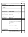
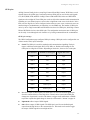
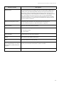
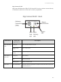
Quick reference for configuring features
This guide primarily focuses on configuring, monitoring, and administering Digi devices from the
web interface. This table provides a quick reference for configuring features and performing
device tasks, and where to find the features and settings in the web interface and this guide. Click
the page number in the Page column to jump to instructions on configuring or using the feature.
Some features are configurable from the command line interface only. In those cases, the
commands that configure the feature are noted. The command descriptions are in the Digi Connect
Family Command Reference.
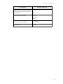
Feature/task
Path to feature in the web interface
See page
Administration/Configuration management:
Administration > File Management
See also the Digi Connect Family Customization and Integration Guide for
information on uploading and downloading files used to customized a Digi
device’s look-and-feel.
151
Python
Applications > Python
116
Backup/restore
Administration > Backup/Restore
155
Update
Administration > Update Firmware
155
Reset
Administration > Factory Default Settings
156
System
Administration > System Information
159
Administration > Reboot
159
Alarms
Configuration > Alarms
95
Autoconnection: automatically
connect a user to a server or network
device
Configuration > Serial Ports > port > Profile Settings > TCP Sockets >
Automatically establish TCP connections
86
File management: uploading and
downloading files, such as applet
files, and custom splash screens.
program file
management.
a configuration
from a TFTP server on the
network
firmware
configuration to factory
defaults
information, including
device identifiers and statistics
Reboot
the Digi device
15
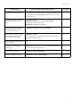
Introduction
Feature/task
Path to feature in the web interface
See page
Connection management:
Management > Serial Ports
145
Management > Connections > Active System Connections
145
Configuration > Network > Advanced Network Settings
82
Ekahau Client™ device-location
software
Applications > Ekahau Client
120
Ethernet settings
Configuration > Network > Advanced Network Settings
82
General Purpose Input/Output (GPIO)
pins
Configuration > GPIO
93
Event logging for the Digi device
Management > Event Logging
145
Help on configuring features
Help button on each page.
Host name for a device
Configuration > Network > Advanced Network Settings > Host Name
82
Industrial Automation (IA)
Configuration > Serial Ports > Select Port Profile > Industrial
Automation
The Industrial Automation port profile should address most configuration
scenarios. To fine-tune your IA settings, use the “set ia” command from the
command line. See the set ia command description in the Digi Connect
Family Command Reference.
For additional information on configuring Industrial Automation, see this
web site:
http://www.digi.com/support/ia
122
IP address settings
Configuration > Network > IP Settings
Configuration > Network > Advanced Settings
46, 66, 82
IP filtering / access control
Configuration > Network > IP Filtering Settings
77
IP forwarding: Network Address
Translation (NAT) and port
forwarding configuration/static routes
Configuration > Network > IP Forwarding Settings
78
Modem emulation
Configuration > Serial Ports > Port Profile Settings >
Modem Emulation
See the Connect Family Command Reference for modem emulation
commands.
88
Manage
serial port connections
Manage
active system
connections
Domain Name System (DNS):
DNS
Client
16
Introduction
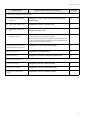
Feature/task
Path to feature in the web interface
See page
Multiple Electrical Interface (MEI)
Currently available in ConnectPort TS models only, and configurable from
command line only. See the set switches command in the Connect Family
Command Reference.
Port logging: enabling port buffering
and displaying contents of a port
buffer
To enable port logging:
Configuration > Serial Ports > Advanced Serial Settings
To display the contents of a port buffer:
Management > Serial Ports > Port Logs
90
Port profiles: sets of preconfigured
serial-port settings for a particular
connection and use scenario
Configuration > Serial Ports > Port Profile Settings
84
Python support: loading and running
custom programs authored in the
Python programming language.
Applications > Python
For more information on writing and running Python programs, see the
Digi Python Programming Guide.
116
Remote Command Interface (RCI) as
a device interface
N/A
38
RealPort (COM port redirection)
configuration
Configuration > Serial Ports > port > Port Profile Settings > RealPort
See also the RealPort Installation Guide.
85
Remote device management
Configuration > Remote Management
105
Reverting configuration settings
Administration > Factory Default Settings
156
17
Introduction
Feature/task
Path to feature in the web interface
See page
Security/access control features:
Control
access to inbound ports
Enable/disable
command-line
access
Secure
Shell Server (SSH)
Establish/change user name for a
user
Issue a new/changed password to
a user
Set
permissions associated with
various services and commands
Configuration > Serial Ports > port > Port Profile Settings >
TCP Sockets or UDP Sockets or Custom port profile
84
Configuration > Serial Ports > port > Port Profile Settings > Local
Configuration > Access the command line interface when connecting
from serial terminals
or
Configuration > Serial Ports > port > Port Profile Settings > Custom >
Access the command line interface
88
Network > Network Services > Enable Secure Shell Server (SSH)
75
Configuration > Users > select a user to change, or select Add New User
for a new user
110
Configuration > Users > select a user to change or select Add New User
for a new user
110
Configuration > Users > select a user to change or add
114
Configuration > Serial Ports > Basic Serial Settings
89
Configuration > Serial Ports > Advanced Serial Settings
90
Configuration > Serial Ports > Port Profile Settings
84
Serial port configuration:
Basic
serial port settings
Advanced
serial port settings
Port
profiles: associate a serial
port with a set of preconfigured
port settings for a specific use
RCI
over serial mode
Configuration > Serial Ports > Advanced Serial Settings
90
RTS
Toggle
Configuration > Serial Ports > Advanced Serial Settings
90
18
Introduction
Feature/task
Path to feature in the web interface
See page
Simple Network Management Protocol (SNMP):
Configure
SNMP through the
web interface
Configuration > System > Simple Network Management Protocol
(SNMP) Settings
102
Enable/disable
SNMP service
Configuration > Network > Network Services
74
Enable/disable
SNMP alarm
Configuration > Alarms > alarm > Send SNMP trap to following
destination when alarm occurs
97, 98
Use
Basic network and serial settings configurable through standard and Digispecific Management Information Blocks (MIBs).
More advanced settings must be set through the web or command-line user
interfaces, and sending alarms as SNMP traps must be configured through
the web interface, on the pages listed above.
39, 134
System information: assign systemidentifying information to a device
Configuration > System > Device Identity Settings
99
Statistics for Digi devices
Administration > System Information
137
Status of Digi devices
Management > Serial Ports, Connections, Network Services
145
Wireless LAN Settings
Configuration > Network > WiFi LAN Settings
70
Wireless Security Settings
Configuration > Network > WiFi Security Settings
71
Wireless 802.1x Authentication
Settings
Configuration > Network > WiFi 802.1x Settings
73
traps
SNMP as primary
configuration interface
Wi-Fi (wireless LAN) devices:
19
Introduction
Hardware features
A summary of hardware features, including power-supply information, is in "Hardware
specifications" on page 169.
For detailed hardware specifications, see the Hardware Reference and data sheet for your Digi
Connect product.
Network interface features
A detailed list of network interface features is in Chapter 7, "Specifications and certifications". See
also the data sheet for your Digi product.
Configurable network services
Access to network services can be enabled and disabled. This means that a device’s use of network
services can be restricted to those strictly needed by the device. To improve device security, nonsecure services, such as Telnet, can be disabled.
Network services that can be enabled or disabled include:
Advanced Digi Discovery Protocol (ADDP): can enable or disable ADDP, but cannot
change its network port number.
RealPort
Encrypted RealPort
HTTP/HTTPS
Line Printer Daemon (LPD)
Remote Login (rlogin)
Remote Shell (rsh)
Simple Network Management Protocol (SNMP)
Telnet
In the web interface, access to network services is enabled and disabled on the Network Services
page of Network Configuration. For more information, see "Network services settings" on page 74.
In the command-line interface, network services are enabled and disabled through the set service
command. See the Digi Connect Family Command Reference for the set service command
description.
20
Introduction
IP protocol support
All Digi devices include a Robust on-board TCP/IP stack with a built-in web server. Supported
protocols include, unless otherwise noted:
Transmission Control Protocol (TCP)
User Datagram Protocol (UDP)
Dynamic Host Configuration Protocol (DHCP)
Simple Network Management Protocol (SNMP)
Secure Sockets Layer (SSL)/Transport Layer Security (TLS)
Telnet Com Port Control Option (Telnet) including support of RFC 2217 (ability to
control serial port through Telnet).See "Serial data communication over TCP and UDP"
on page 22 for additional information.
Remote Login (rlogin)
Line Printer Daemon (LPD)
HyperText Transfer Protocol (HTTP)/HyperText Transfer Protocol over Secure Socket
Layer (HTTPS)
Simple Mail Transfer Protocol (SMTP)
Internet Control Message Protocol (ICMP)
Internet Group Management Protocol (IGMP)
Address Resolution Protocol (ARP)
Advanced Digi Discovery Protocol (ADDP)
Network Address Translation (NAT)/Port Forwarding
Following is an overview of some of the services provided by these protocols.
21
Introduction
Serial data communication over TCP and UDP
Digi devices support serial data communication over TCP and UDP. Key features include:
Serial data communication over TCP, also known as autoconnect and tcpserial can
automatically perform the following functions:
–
Establish bidirectional TCP connections, known as autoconnections, between the serial
device and a server or other network device. Autoconnections can be made based on
data and or serial hardware signals.
–
Control forwarding characteristics based on size, time, and pattern
–
Allow incoming raw, Telnet, and SSL/TLS (secure-socket) connections
–
Support RFC 2217, an extension of the Telnet protocol
Serial data communication over UDP, also known as udpserial, can automatically
perform the following functions:
–
Digi Connect products can automatically send serial data to one or more devices or
systems on the network using UDP sockets. Options for sending data include whether
specific data is on the serial line, a specific time period has elapsed, or after the specified
number of bytes has been received on the serial port.
–
Control forwarding characteristics based on size, time, and patterns.
–
Support incoming datagrams from multiple destinations.
–
Support outgoing datagrams sent to multiple destinations.
TCP/UDP forwarding characteristics.
Extended communication control on TCP/UDP data paths.
–
Timeout
–
Hangup
–
User-configurable Socket ID string (text string identifier on autoconnect only)
Dynamic Host Configuration Protocol (DHCP)
Dynamic Host Configuration Protocol (DHCP) can be used to automatically assign IP addresses,
deliver TCP/IP stack configuration parameters such as the subnet mask and default router, and
provide other configuration information. For further details, see "Configure an IP address using
DHCP" on page 48.
Auto-IP
Auto-IP is a protocol that will automatically assign an IP address from a reserved pool of standard
Auto-IP addresses to the computer on which it is installed. For Digi devices are set to obtain its IP
address automatically from a DHCP server and the DHCP server is unavailable or nonexistent,
Auto-IP will assign the device an IP address. For further details, see "Configure an IP address
using Auto-IP" on page 48.
22
Introduction
Simple Network Management Protocol (SNMP)
Simple Network Management Protocol (SNMP) is a protocol for managing and monitoring
network devices. SNMP architecture enables a network administrator to manage nodes--servers,
workstations, routers, switches, hubs, etc.--on an IP network; manage network performance, find
and solve network problems, and plan for network growth. Digi devices support SNMP Versions 1
and 2. For more information on SNMP as a device-management interface, see "Simple Network
Management Protocol (SNMP)" on page 39. For a list SNMP-related of supported Request for
Comments (RFCs) and Management Information Bases (MIBs), see page 102.
Secure Sockets Layer (SSL)/Transport Layer Security (TLS)
Secure Sockets Layer (SSL)/Transport Layer Security (TLS) are used to provide authentication
and encryption for Digi devices. For more information, see "Security features in Digi devices" on
page 26.
Telnet
Digi devices support the following types of Telnet connections:
Telnet Client
Telnet Server
Reverse Telnet, often used for console management or device management
Telnet Autoconnect
RFC 2217, Telnet Com Port Control Option, an extension of the Telnet protocol
For more information on these connections, see "Supported connections and data paths in Digi
devices" on page 28. Access to Telnet network services can be enabled or disabled.
Remote Login (rlogin)
Users can perform logins to remote systems (rlogin). Access to rlogin service can be enabled or
disabled.
Line Printer Daemon (LPD)
The Line Printer Daemon (LPD) allows network printing over a serial port. Each serial port has a
dedicated LPD server that is independently configurable. Access to LPD service can be enabled or
disabled.
HyperText Transfer Protocol (HTTP)
HyperText Transfer Protocol over Secure Socket Layer (HTTPS)
Digi devices provide web pages for configuration that can be secured by requiring a user login.
Internet Control Message Protocol (ICMP)
ICMP statistics can be displayed, including the number of messages received, bad messages
received, and destination unreachable messages received.
23
Introduction
Point-to-Point Protocol (PPP)
The Point-to-Point Protocol (PPP) transports multi-protocol packets over point-to-point links. PPP
encapsulates the data packet, allows the server to inform the dial-up client of its IP address (or
client to request the IP address), authenticates the exchange, negotiates multiple protocols, and
reassembles the data packet for network communication.
Advanced Digi Discovery Protocol (ADDP)
The Advanced Digi Discovery Protocol (ADDP) runs on any operating system capable of sending
multicast IP packets on a network. ADDP allows the system to identify all ADDP-enabled Digi
devices attached to a network by sending out a multicast packet. The Digi devices respond to the
multicast packet and identify themselves to the client sending the multicast.
ADDP communicates with the TCP/IP stack using UDP. The TCP/IP stack should be able to
receive multicast packets and transmit datagrams on a network.
Not all Digi devices support ADDP. Access to ADDP service can be enabled or disabled, but the
network port number for ADDP cannot be changed from its default.
24
Introduction
RealPort software
Digi devices use the patented RealPort COM/TTY port redirection for Microsoft Windows, UNIX,
and Linux environments. RealPort software provides a virtual connection to serial devices, no
matter where they reside on the network. The software is installed directly on the host PC and
allows applications to talk to devices across a network as though the devices were directly attached
to the host. Actually, the devices are connected to a Digi device somewhere on the network.
RealPort is unique among COM port re-directors because it is the only implementation that allows
multiple connections to multiple ports over a single TCP/IP connection. Other implementations
require a separate TCP/IP connection for each serial port. Unique features also include full
hardware and software flow control, as well as tunable latency and throughput. Access to RealPort
services can be enabled or disabled.
Encrypted RealPort
Digi devices also support RealPort software with encryption. Encrypted RealPort offers a secure
Ethernet connection between the COM or TTY port and a device server or terminal server.
Encryption prevents internal and external snooping of data across the network by encapsulating the
TCP/IP packets in a Secure Sockets Layer (SSL) connection and encrypting the data using
Advanced Encryption Standard (AES), one of the latest, most efficient security algorithms. Access
to Encrypted RealPort services can be enabled or disabled. Digi’s RealPort with encryption driver
has earned Microsoft’s Windows Hardware Quality Lab (WHQL) certification. Drivers are
available for a wide range of operating systems, including Microsoft Windows Server 2003,
Windows XP, Windows 2000, Windows NT, Windows 98, Windows ME; SCO Open Server;
Linux; AIX; Sun Solaris SPARC; Intel; and HP-UX. It is ideal for financial, retail/point-of-sale,
government or any application requiring enhanced security to protect sensitive information.
Alarms
Digi devices can be configured to issue alarms, in the form of email message or SNMP traps, when
certain device events occur. These events include changes in GPIO signals, certain data patterns
being detected in the data stream,. Receiving alarms about these conditions provides the advantage
of notifications being issued when events occur, rather than having to monitor the device on an
ongoing basis to determine whether these events have occurred. Alarms can also be forwarded to
the iDigi platform for display and management in that platform. For more information on
configuring alarms, see "Alarms" on page 95.
Modem emulation
Digi devices include a configuration profile that allows the device to emulate a modem. Modem
emulation sends and receives modem responses to a serial device over TCP/IP (including Ethernet)
instead of Public Switched Telephone Network (PSTN). The modem emulation profile allows
maintaining a current software application but using it over the less expensive Ethernet network. In
addition, Telnet processing can be enabled or disabled on the incoming and outgoing modememulation connections.The modem-emulation commands supported in Digi devices are
documented in the Digi Connect Family Command Reference.
25
Introduction
Security features in Digi devices
Secure access and authentication
One password, one permission level.
Passwords can be issued to device users.
Selective enabling/disabling network services such as ADDP, RealPort, Encrypted
RealPort, HTTP/HTTPS, LPD, Remote Login, Remote Shell, SNMP, and Telnet.
Can control access to inbound ports.
Can control access to specific devices, IP addresses, or networks through IP filtering.
Secure sites for configuration: HTML pages for configuration have appropriate security.
User and user group access permissions, which control user access to various features
and the level of control they have over them (view settings or change settings).
Encryption
Encrypted RealPort offers encryption for the Ethernet connection between the COM/
TTY port and the Digi device. Encryption prevents internal and external snooping of
data across the network by encapsulating the TCP/IP packets in a Secure Sockets Layer
(SSL) connection and encrypting the data using the Advanced Encryption Standard
(AES) security algorithm.
Strong Secure Sockets Layer (SSL) V3.0/ Transport Layer Security (TLS) V1.0-based
encryption: DES (64-bit), 3DES (192-bit), AES (128-/192-/256-bit), IPsec ESP: DES,
3DES, AES.
Wireless Digi Connect products provide Wi-Fi Protected Access (WPA/WPA2/802.11i)
and Wired Equivalent Privacy (WEP) encryption (64-/128-bit). Supported WPA/WPA2/
802.11i authentication methods are:
Supported WPA authentication methods
EAP-TLS
PEAP
EAP/TTLS
LEAP (WEP only)
EAP-PEAP/MSCHAPv2 (both PEAPv0 and PEAPv1)
EAP-TTLS/EAP-MD5-Challenge
EAP-PEAP/TLS (both PEAPv0 and PEAPv1)
EAP-TTLS/EAP-GTC
EAP-PEAP/GTC (both PEAPv0 and PEAPv1)
EAP-TTLS/EAP-OTP
EAP-PEAP/OTP (both PEAPv0 and PEAPv1)
EAP-TTLS/EAP-MSCHAPv2
EAP-PEAP/MD5-Challenge (both PEAPv0 and PEAPv1)
EAP-TTLS/EAP-TLS
EAP-TTLS/MSCHAPv2
EAP-TTLS/MSCHAP
EAP-TTLS/PAP
EAP-TTLS/CHAP
SNMP security
SNMP “set” commands can be disabled to make use of SNMP read-only. Changing public and
private community names is recommended to prevent unauthorized access to the device.
26
Introduction
Configuration management
Once a Digi device is configured and running, configuration-management tasks need to be
periodically performed, such as:
Upgrading firmware
Copying configurations to and from a remote host
Software and factory resets
Rebooting the device
Memory management
File management
For more information on these configuration-management tasks, see Chapter 5, "Digi device
administration".
Customization capabilities
Several aspects of using Digi devices can be customized. For example:
The look-and-feel of the device interface can be customized, to use a different company
logo or screen colors.
Custom Java applets can be created, using the Java configuration applet as a sample for
further development.
Custom applications written in Python can be executed.
Custom factory defaults to which devices can be reverted can be defined.
The Digi Connect Family Customization and Integration Guide (Part Number 90000734; available
with the Digi Connect Integration Kit) describes customization and integration tools and processes.
Contact Digi International for more information on the Digi Connect Integration Kit customization
tools and resources and for assistance with customization efforts.
The Digi Connect Integration Kit provides a platform for evaluation, rapid prototyping, and
integration of Digi Connect embedded modules with plug-and-play firmware. It includes tools,
sample code, and documentation to help with product integration and web-based customization
efforts.
27
Introduction
Supported connections and data paths in Digi devices
Digi devices allow for several kinds of connections and paths for data flow between the Digi
device and other entities. These connections can be grouped into two main categories:
Network services, in which a remote entity initiates a connection to a Digi device.
Network/serial clients, in which a Digi device initiates a network connection or opens a
serial port for communication.
This discussion of connections and data paths may be helpful in understanding the effects of
enabling certain features and choosing certain settings when configuring Digi products.
Network services
A network service connection is one in which a remote entity initiates a connection to a Digi
device. There are several categories of network services:
Network services associated with specific serial ports
Network services associated with serial ports in general
Network services associated with the command-line interface (CLI)
Network services associated with specific serial ports
Reverse Telnet: A telnet connection is made to a Digi device, in which data is passed
transparently between the telnet connection and a named serial port.
Reverse raw socket: A raw TCP socket connection is made to a Digi device, in which
data is passed transparently between the socket and a named serial port.
Reverse TLS socket: An encrypted raw TCP socket is made to a Digi device, in which
data is passed transparently to and from a named serial port.
LPD: A TCP connection is made to a named serial port, in which the Digi device
interprets the LPD protocol and sends a print job out of the serial port.
Modem emulation, also known as Pseudo-modem (pmodem): A TCP connection is
made to a named serial port, and the connection will be “interpreted” as an incoming
call to the pseudo-modem.
28
Introduction
Network services associated with serial ports in general
RealPort: A single TCP connection manages (potentially) multiple serial ports.
Modem emulation, also known as pseudo-modem (pool): A TCP connection to the
“pool” port is interpreted as an incoming call to an available pseudo-modem in the
“pool” of available port numbers.
rsh: Digi devices support a limited implementation of the Remote shell (rsh) protocol,
in that a single service listens to connections and allows a command to be executed.
Only one class of commands is allowed: a single integer that specifies which serial port
to connect to. Otherwise, the resulting connection is somewhat similar to a reverse telnet
or reverse socket connection.
DialServ: Connecting a DialServ device to the serial port. DialServ simulates a public
switched telephone network (PSTN) to a modem and forwards the data to the serial port.
The Digi device sends and receives the data over an IP network.
Network services associated with the command-line interface
Telnet: A user can Telnet directly to a Digi device’s command-line interface.
rlogin: A user can perform a remote login (rlogin) to a Digi device’s command-line
interface.
29
Introduction
Network/serial clients
A network/serial client connection is one in which a Digi device initiates a network connection or
opens a serial port for communication. There are several categories of network/serial client
connections:
Autoconnect behavior client connections
Command-line interface (CLI)-based clients
Modem emulation (pseudo-modem) client connections
Autoconnect behavior client connections
In client connections that involve autoconnect behaviors, a Digi device initiates a network
connection based on timing, serial activity, or serial modem signals. Autoconnect-related client
connections include:
Raw TCP connection: The Digi device initiates a raw TCP socket connection to a
remote entity.
Telnet connection: The Digi device initiates a TCP connection using the Telnet
protocol to a remote entity.
Raw TLS encrypted connection: The Digi device initiates an encrypted raw TCP
socket connection to a remote entity.
Rlogin connection: The Digi device initiates a TCP connection using the rlogin
protocol to a remote entity.
Command-line interface (CLI)-based client connections
Command-line interface based client connections are available for use once a user has established
a session with the Digi device’s CLI. CLI-based client connections include:
telnet: A connection is made to a remote entity using the Telnet protocol.
rlogin: A connection is made to a remote entity using the Rlogin protocol.
connect: Begin communicating with a local serial port.
Modem emulation (pseudo-modem) client connections
When a port is in the modem-emulation or pseudo-modem mode, it can initiate network
connections based on AT command strings received on the serial port.The AT commands for
modem emulation are documented in the Digi Connect Family Command Reference.
30
Introduction
Interfaces for configuring, monitoring, and administering Digi devices
There are several interfaces for configuring, monitoring, and administering Digi devices. These
interfaces are covered in more detail later in this guide.
Configuration capabilities
Device configuration involves setting values and enabling features for such areas as:
Network configuration: Specifying the device’s IP address settings, network-service
settings, and advanced network settings.
Serial port configuration: Specifying the serial port characteristics for the device.
GPIO pin configuration (for all devices except Digi Connect SP, Digi Connect Wi-SP):
Specifying how the various GPIO pins for the device will be used.
Alarms: Defining whether alarms should be issued, the conditions that trigger alarms,
and how the alarms should be delivered.
Security/Users configuration: Configuring security features, such as whether password
authentication is required for device users.
System configuration: Specifying system-identifying information, such as a device
description, contact person, and physical location.
Configuration interfaces
Several interfaces are available for configuring Digi devices, including:
The Digi Device Setup Wizard, which helps set up an IP address for the device and
quickly configure features.
The Digi Device Discovery Utility, which locates Digi devices on a network, and allows
opening the web interface for the devices.
The iDigi platform, a configuration interface to fine-tune or monitor devices. The iDigi
Platform cannot assign an IP address but it can change one.
A web-based interface embedded with the product, providing device configuration
profiles for quick serial-port configuration and other settings.
An optional Java applet that can be used for device configuration, and as a sample
application for customization and further application development.
A command-line interface (CLI).
Remote Command-line Interface (RCI) protocol
Simple Network Management Protocol (SNMP).
31
Introduction
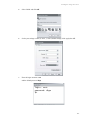
The Digi Device Setup wizard
The Digi Device Setup Wizard is a wizard for quick initial configuration of Digi devices. It is
available from the Digi Support site and also provided on the Software and Documentation CD
shipped with each product. It assigns an IP address for the device, configures the device’s serial
port parameters based on a selected configuration scenario called a port profile, and determines
whether RealPort software needs to be installed.
For most users, the Digi Device Setup Wizard interface provides adequate device configuration.
Device configuration is made easier by providing a set of port profiles which configure a serial port
based on the way the port will be used. Each port profile displays the relevant settings for the
configuration. There are several profile choices, including Console Management, TCP Sockets,
UDP Sockets, Serial Bridging, Modem Emulation, and a Custom profile.
The Digi Device Setup Wizard is intended to be run only once, and is not installed on a user’s PC.
While the wizard is available in Microsoft Windows or UNIX platforms, it requires Microsoft
Windows for full support, and the PC running Windows usually needs to be on same network
segment as the Digi device. The Unix version of the Wizard does not include all the features of the
Windows version. The Unix version is limited to network configuration settings, and does not
allow configuring or choosing a scenario through port profiles.
Some sites disallow users from running wizards, which would prevent users at such sites from
using this interface. The device discovery responses can be blocked by personal firewalls, VPN
software, and certain network equipment. Disabling personal firewalls is not always possible.
While the configuration capabilities of the Digi Device Setup Wizard are acceptable for most Digi
device users, it only provides for the most common configuration scenarios, and is not as flexible
as configuring through the web interface or the command line.
To access the Digi Device Setup Wizard, insert the Software and Documentation CD that
accompanies the Digi device in a PC’s CD drive. The Digi Device Setup Wizard will automatically
start. See "Configuration through the Digi Device Setup Wizard" on page 56 and the wizard’s
online help for more information.
32
Introduction
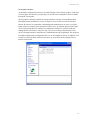
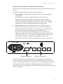
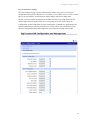
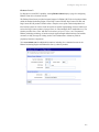
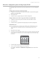
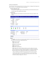
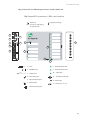
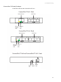
Digi Device Discovery utility
The Digi Device Discovery utility locates Digi devices on a network and allows for opening the
web interface for discovered devices, configuring network settings, and rebooting the device. It
uses a Digi International-proprietary protocol, Advanced Digi Discovery Protocol (ADDP), to
discover the Digi devices on a network, and displays the discovered devices in a list, for example:
Digi Device Discovery quickly locates Digi devices and basic device information, such as the
device’s address, firmware revision, and whether it has been configured. It runs on any operating
system that can send multicast IP packets to a network. It sends out a User Datagram Protocol
(UDP) multicast packet to all devices on the network. Devices supporting ADDP reply to this UDP
multicast with their configuration information. Even devices that do not yet have an IP address
assigned or are misconfigured for the subnet can reply to the UDP multicast packet and be
displayed in device discovery results.
Not all Digi devices support ADDP. Note that Device discovery responses can be blocked by
personal firewalls, Virtual Private Network (VPN) software, and certain network equipment.
Firewalls will block UDP ports 2362 and 2363 that ADDP uses to discover devices.
Digi Device Discovery is available on the Software and Documentation CD. After installation, it is
available from the Start menu. Access to the ADDP service can be enabled or disabled, but the
network port number for ADDP cannot be changed from its default. For more information on the
Digi Device Discovery utility, see page 58.
33
Introduction
iDigi™ Platform interface
The iDigi Platform provides remote network management of all connected hardware. In contrast to
the one-user-to-one device model of other Digi device interfaces, the iDigi Platform uses a oneuser-to-many-devices interface model. By providing a central point of access to remote devices or
groups of devices, the iDigi Platform makes it easier for you to manage many devices. Using a
standard Web browser, from the iDigi Platform, you can configure network hardware; track device
performance; remotely set filters and alarms; monitor connections, device status and statistics;
reboot devices; reset defaults, and remotely upgrade firmware. Because you can diagnose and
solve problems from a central site, resulting in fewer maintenance trips to remote locations, iDigi
Platform helps you reduce maintenance costs.
For more information on the iDigi Platform as an remote management interface, see these
resources:
"Remote management settings" on page 105. This section shows how to configure
settings within Digi devices so that they can be handled through a remote device
manager such as the iDigi Platform.
"Configuration through the iDigi Platform" on page 50.
"Monitoring capabilities from the iDigi Platform" on page 136
iDigi tutorials and guides
34
Introduction
Web interface
A web interface is provided as an easy way to configure and monitor Digi devices. Configurable
features are grouped into several categories. These categories vary by product; examples include
Network, Serial Port, GPIO (for all products except Digi Connect SP, Digi Connect Wi-SP),
Alarms, System, Remote Management, UsersSecurity. Most of the configurable features are
arranged by most basic settings on a page, with associated and advanced settings accessible from
that page. Serial-port configurations are classified into port profiles, or configuration scenarios that
best represents the environment in which the Digi device will be used. Selecting a particular port
profile configures the serial port parameters that are needed. For some features, it may be desirable
to establish a basic configuration using the Digi Device Setup Wizard, and then fine-tune the
configuration using the web interface.
To access the web interface, enter the Digi device’s IP address or host name in a browser’s URL
window. The main menu of the web interface is displayed. For more information, see
"Configuration through the web interface" on page 58. The web interface has a tutorial, accessed
from the Home page, and online help, accessed from the Help link on each page.
Not all settings provided by the command-line interface are displayed in the web interface.
However, the configuration settings in the web interface should be sufficient for most users. If
necessary, settings can be modified later from the command line.
35
Introduction
Java applet interface
An alternative configuration interface is provided with Digi Connect Family products, in the form
of a Java applet. This interface provides many, but not all, of the configuration choices available
through the web interface.
The Java applet is primarily intended as a sample alternative interface for embedded products.
Embedded product manufacturers can use the applet as a base for their custom user interface.
Because the interface is customizable, embedded product manufacturers can use it to provide a
totally unique user interface that represents the kind of device in which the Digi Connect Family
device is being embedded. For example, the configuration interface for a printer would look
nothing like the web interface. Today, the only way to create a totally custom interface to the
device is through an applet or other Remote Command Interface (RCI) application. The applet can
be slightly modified using a configuration file, or it can be changed extensively. In addition, it can
be used as a sample by those customers who choose to writer their custom configuration user
interface from scratch.
36
Introduction
The Java applet interface is a completely customizable interface. For example, the web interface
can be changed by replacing the Digi logo with your company logo or changing the colors used in
the interface workspace.
The Java applet can also be used as a basis for further interface development. That is, if the Java
applet is adequate for most configuration needs, but needs some modifications, the applet’s
operation can be customized. If a totally unique user interface is desired, the Java applet can serve
as a sample program and a starting point from which to build new interfaces. It illustrates such
concepts as configuring various aspects of the device using the RCI, applet packaging, and Swing
user interface. Custom management applications can be written in other languages that run on a
separate system in the network and talk to the device using RCI. For example, a printer
manufacturer might have a configuration utility written in C++ that is installed on the PC along
with the print driver.
The Java applet requires that the Sun Java Runtime environment be loaded. It does not allow for
configuration of as many features as the web interface. The interface is essentially frozen, and has
not been updated with additional configurable features that are available in the web interface.
There is limited online help for the Java applet configuration screens. For more information on
configurable areas, fields, and selectable values, review the online help for the web interface.
Access the Java applet interface from the User Interface section of the Home page of the web
interface. Either click the Launch button next to the Custom Interface option, or click the Set as
Default to set the Java applet as the default device interface. In some cases, a Digi device’s default
device interface may have already been preset to the Java applet by a system administrator.
See Chapter 3, "Configure Digi devices" for more information on using the Java applet to
configure devices. While that chapter primarily focuses on configuring Digi Connect Family
devices from the web interface, it also covers configuration from the Java applet, primarily the
differences from the web interface.
37
Introduction
Command-line interface
Digi devices can be configured by issuing commands from the command line. The command-line
interface allows communication directly without a graphical interface. To access the command line
from the Digi Device Discovery utility, click Telnet to command line.
For example, here is a command issued from the command line to set general serial configuration
options:
#> set serial baudrate=9600 flowcontrol=hardware
The command-line interface provides flexibility for making precise changes to device
configuration settings and operation. It does require users to have experience issuing commands,
and access to command documentation.
The command line is available through Telnet or SSH TCP/IP connections, or through serial port
using terminal emulation software such as Hyperterminal. Access to the command line from serial
ports depends on the port profile in use by the port. By default, serial port command-line access is
allowed.
See "Configuration through the command line" on page 131 for more information on this interface.
See the Digi Connect Family Command Reference for command descriptions and examples of
entering configuration commands from the command-line interface. In addition, online help is
available for the commands, through the help and ‘?’ commands.
Remote Command Interface (RCI)
Remote Command Interface (RCI) is a programmatic interface for configuring and controlling
Digi devices. RCI is an XML-based request/response protocol that allows a caller to query and
modify device configurations, access statistics, reboot the device, and reset the device to factory
defaults. Unlike other configuration interfaces that are designed for a user, such as the commandline or web interfaces, RCI is designed to be used by a program. RCI access consists of program
calls. A typical use of RCI is in a Java applet that can be stored on the Digi device to replace the
web interface with a custom browser interface. Another example is a custom application running
on a PC that monitors and controls an installation of many Digi devices.
As RCI is designed to be used by a program, it is useful for creating a custom configuration user
interface, or utilities that configure or initialize devices through external programs or scripts.
RCI uses HTTP as the underlying transport protocol. Depending on the network configuration, use
of HTTP as a transport protocol could be blocked by some firewalls.
RCI is quite complex to use, requiring users to phrase configuration requests in Extensible Markup
Language (XML) format. It is a “power-user” option, intended more for users developing their
own user interfaces, or for users implementing embedded control (and thus potentially using RCI
over serial) than for end-users with limited knowledge of device programming.
Not all actions in the web interface have direct equivalents in RCI. Therefore, it may not be easy
for some end-users to determine what needs to be sent through XML for a particular style of
request.
For more details on RCI, see the Digi Connect Integration Kit and the Remote Command Interface
(RCI) Specification.
38
Introduction
Simple Network Management Protocol (SNMP)
Simple Network Management Protocol (SNMP) is a protocol for managing and monitoring
network devices. The SNMP architecture enables a network administrator to manage nodes-servers, workstations, routers, switches, hubs, etc.--on an IP network; manage network
performance, find and solve network problems, and plan for network growth. Digi devices support
SNMP Versions 1 and 2.
SNMP is easy to implement in extensive networks. Programming new variables and “dropping in”
new devices in a network are easy. SNMP is widely used. It is a standard interface that integrates
well with network management stations in an enterprise environment. While its capabilities are
limited to device monitoring and display of statistics in Digi devices, read/write capabilities are
expected to be added to Digi devices in future releases.
However, because device communication is UDP-based, the communication is not secure. If more
secure communications with a device are required, use an alternate device interface. SNMP does
not allow for certain task that can be performed from the web interface, such as file management,
uploading firmware, or backing up and restoring configurations. Compared to the web or
command-line interfaces, SNMP is limited in its ability to set specific parameters, such as set port
profile, is not possible.
Accessing the SNMP interface requires a tool, such as a network management station. The
management station relies on an agent at a device to retrieve or update the information at the
device, including Device configuration, status, and statistical information. This information is
viewed as a logical database, called a Management Information Base (MIB). MIB modules
describe MIB variables for a variety of device types and computer hardware and software
components.
A variety of resources about SNMP are available, including reference books, overviews, and other
files on the Internet. For an overview of the SNMP interface and the components of MIB-II, go to
http://www.rfc-editor.org/rfcsearch.html, and search for MIB-II. From the results, locate the text
file describing the SNMP interface, titled Management Information Base for Network
Management of TCP/IP-based internets: MIB-II. The text of the Digi enterprise MIBs can also be
displayed.
For additional discussion of using SNMP as a device monitoring interface, see "Monitoring
Capabilities from SNMP" on page 149.
39
Introduction
Monitoring capabilities and interfaces
Monitoring Digi devices includes such tasks as checking device status, viewing information on a
device’s GPIO pins, checking runtime state, viewing serial port operations, and reviewing network
statistics, and managing their connections. There are several interfaces for monitoring Digi devices
and managing their connections.
As with device configuration, there are several interfaces available for monitoring Digi devices,
including, the web interface embedded with the product, the optional Java applet, SNMP,
command-line interface, and the iDigi Platform. These interfaces are covered in more detail in
Chapter 4, "Monitor and manage Digi devices"
The iDigi Platform
In the iDigi Platform, monitoring capabilities can be sorted by the server and the devices managed
by the server. The information is available in logs and can be generated into reports. When
available, the reports post linked totals that can be drilled back to the original devices that make up
the activity of the report.
Web and Java Applet interface s
The web interfaceand the optional Java applet interface have several screens for monitoring Digi
devices:
Network Status
Serial Port Management: for each port, the port’s description, current profile, and
current serial configuration.
Connections Management: A display of all active system connections.
System Information: general device information; current GPIO pin states; serial port
information for each port, including the port’s description, current profile, and current
serial configuration (the same information displayed by choosing Serial Port
Management); and network statistics.
Command-line interface
Several commands can be issued from the command line to monitor devices. For a review of these
commands and what they can provide from a device-monitoring perspective, see "Monitoring
capabilities from the command line" on page 146.
SNMP
Monitoring capabilities of SNMP include managing network performance, gathering device
statistics, and finding and solving network problems. For more information on using SNMP for
device-monitoring purposes, see "Monitoring Capabilities from SNMP" on page 149.
40
Introduction
Device administration
Periodically, administrative tasks need to be performed on Digi devices, such as uploading and
managing files, changing the password for logging onto the device, backing up and restoring
device configurations, updating firmware, restoring the configuration to factory defaults, and
rebooting.
As with configuration and monitoring, administration can be done from a number of interfaces,
including the web interface, command line, and the iDigi Platform. See Chapter 5, "Digi device
administration" for more information and procedures.
41
Hardware installation
Hardware installation
C
H
A
P
T
E
R
2
This section details requirements and recommendations for installing ConnectPort TS Family
products.
For the Digi Connect ES, see the Hardware Setup Guide. For all other Digi Connect Family
products, see their Hardware Reference Manuals for hardware-installation details.
42
Hardware installation
Rack mounting (ConnectPort TS 16 only)
ConnectPort TS 16 models can be optionally mounted to a rack, available separately.
Installation
1
Attach enclosed bracket ears to rack as shown in illustration.
Rack shown in illustration is not
included with Digi device.
2
Follow safety and installation considerations when placing the Digi device on the rack.
43
Hardware installation
Safety and installation considerations
Physical location and spacing
Install equipment in Restricted Access Areas only (dedicated equipment rooms/closets)
in accordance with Articles 110-16, 110-17, and 110-18 of the National Electrical Code,
ANSI/NFPA 70.
To ensure proper ventilation and air flow for units, provide at least 12 inches (30
centimeters) of clearance on all sides for each unit.
Distribute weight evenly in the rack to avoid overloading.
Temperature
Elevated operating ambient temperature: If installed in a closed or multi-unit rack
assembly, the operating ambient temperature of the rack environment may be greater
than room ambient temperature. Install rack-mounted equipment in an environment
compatible with the manufacturer’s maximum rated ambient temperature (Tmra).
For a rack setup with forced air, the device can run 0-55° C with no extra space above or
below the device (default design of the ConnectPort TS 16 Rack provides 1/16” = 2mm
between devices).
For a rack setup with no forced air, make sure the air in-between devices does not get
warmer than 55°C by providing space between the devices, controlling the ambient
temperature on the rack, distributing weight evenly in the rack to avoid overloading,
checking equipment nameplate ratings before connecting to the supply circuit, and
maintaining reliable earthing of the rack-mounted equipment.
Power and wiring:
This equipment is for indoor use and all the communication wirings are limited to inside
of the building.
Locate the AC supply source within the same premises as the equipment is to be used.
Check equipment nameplate ratings before connecting to the supply circuit to avoid
overloads that may damage over-current protection devices and supply wiring.
As needed maintain reliable earthing of rack-mounted equipment.
44
Configure Digi devices
Configure Digi devices
C
H
A
P
T
E
R
3
This chapter describes how to configure a Digi device. It covers these topics:
"Default IP address and methods for assigning an IP address" on page 46
"Configuration through the iDigi Platform" on page 50
"Configuration through the Digi Device Setup Wizard" on page 56.
"Configuration through the web interface" on page 58
"Alternative configuration options for Digi Connect Wi-SP" on page 123
"Configuration through the Java applet interface" on page 126
"Configuration through the command line" on page 131
"Configuration through Simple Network Management Protocol (SNMP)" on page 134
"Batch capabilities for configuring multiple devices" on page 134
To use the Digi Device Setup Wizard for initial configuration, see the online help for the Wizard.
For instructions on launching the wizard, see "Assign an IP address using the Digi Device Setup
Wizard" on page 47.
45
Configure Digi devices
Default IP address and methods for assigning an IP address
All products that have a cellular (WAN) interface ship with static IP address for the Ethernet port
of 192.168.1.1 and DHCP server enabled by default. The Ethernet port of the laptop should be
configured to automatically receive an IP address and DNS server address.
All products that only have an Ethernet or Wi-Fi (LAN) interface ship with DHCP client enabled
by default. Accessing the web interface on these products is most easily done by connecting it to a
LAN that has a DHCP server.
To discover which IP address has been assigned to the device, use the Device Discovery Utility for
Windows, available on the Software and Documentation CD. See installation instructions on
page 58.
There are several ways to assign an IP address to a Digi device, described on the following pages:
Assign a specific IP address to a device, through the Digi Device Setup Wizard.
Use Dynamic Host Configuration Protocol (DHCP) from the web interface.
Use the command-line interface.
Use Automatic Private IP Addressing (APIPA), also known as Auto-IP.
Note For the Digi Connect ES 4/8 SB with Switch device, special considerations apply
when assigning IP addresses, owing to the two Ethernet interfaces on the product. See
page 67.
46
Configure Digi devices
Assign an IP address using the Digi Device Setup Wizard
The Digi Device Setup Wizard is included on the Software and Documentation CD for your
product. Using this wizard is the easiest way to assign an IP address and initially configure Digi
devices. It discovers Digi devices on a network, configures an IP address for a Digi device, and
configures basic serial port parameters according to how the device will be used. After this initial
configuration, features can be fine-tuned as needed through the web interface. Setup is specially
designed for the Windows environments, and is quick, automated, and complete.
To use the Digi Device Setup Wizard:
1
Connect the Digi device to the network and power it on.
2
Locate the MAC address for the Digi device; it is on a label on the bottom of the product.
Record it for later use in assigning an IP address.
3
Insert the Software and Documentation CD in the CD drive of a computer running
Microsoft Window.s If the CD does not start automatically, double-click
My Computer > CD ROM Drive > setup.exe.
4
The Digi Device Setup Wizard automatically starts. Select the appropriate platform and
click Next.
The Digi device discovery utility finds and lists all of the Digi devices on the network.
5
Locate the Digi device by its MAC address.
6
Select the Digi device and click Next.
7
Follow the instructions in the wizard to assign an IP address for the Digi device. Use the
online help supplied with the wizard for information about values and selections on the
wizard screens. For additional information about configuration settings displayed on the
wizard screens, continue to "Configuration through the Digi Device Setup Wizard" on page
56.
47
Configure Digi devices
Configure an IP address using DHCP
An IP address can also be configured using Dynamic Host Configuration Protocol (DHCP). DHCP
is an Internet protocol for automating the configuration of computers that use TCP/IP. DHCP can
be used to automatically assign IP addresses and deliver TCP/IP stack configuration parameters.
As mentioned previously, all products that have a cellular (WAN) interface ship with static IP
address for the Ethernet port of 192.168.1.1 and DHCP server enabled by default. All products that
only have an Ethernet or Wi-Fi (LAN) interface ship with DHCP client enabled by default.
This procedure assumes that the Digi device is configured as a DHCP client. Since this is the
default configuration, this will be the case unless the configuration has been changed.
1
Make sure the Digi device is not powered on.
2
If desired, set up a permanent entry for the Digi device on a DHCP server. While this is not
necessary to obtain an IP address via DHCP, setting up a permanent entry means the IP
address will be saved after the device is rebooted.
3
Connect the Digi device to the network and power it on. The IP address configured in step 2
is assigned automatically.
Configure an IP address using Auto-IP
The standard protocol Automatic Private IP Addressing (APIPA or Auto-IP) automatically assigns
the IP address from a group of reserved IP addresses to the device on which Auto-IP is installed.
Use Digi Device Discovery or DHCP to find the Digi device and assign it a new IP address that is
compatible with your network. Once the unit is plugged in, Auto-IP automatically assigns the IP
address. Auto-IP addresses are typically in the 169.254.x.x address range.
48
Configure Digi devices
Configure an IP address from the command-line interface
The set network command configures an IP address from the command line. Include the following
parameters:
ip=device ip: The IP address for the device.
gateway=gateway: The network gateway IP address.
submask=device submask: The device subnet mask.
dhcp=off: Turns off use of the Dynamic Host Configuration Protocol (DHCP), so that
the IP address assigned is permanent.
static=on: Specifies that the IP address is static, and will remain as the specified IP
address, gateway, and submask.
For example:
set network ip=10.0.0.100 gateway=10.0.0.1
submask=255.255.255.0 dhcp=off static=on
To configure the Digi Connect SP through the command line, the DIP switches must be changed.
See "Command line access" on page 123 for an illustration of the DIP switch settings.
IP addresses and the iDigi Platform
From the iDigi Platform interface the Ethernet/LAN address for a Digi device can be changed
only; an address cannot be assigned. The mobile/cellular device is typically provided by the
mobile service provider; check with your mobile service provider on how they handle addresses.
To change the IP address, open the web interface for based on the IP address the device has and
navigate to Configuration > Network > IP Settings. On the IP Settings page, enter the new IP
address, subnet mask, and gateway.
Test the IP address configuration
Once the IP address is assigned, make sure it works as configured.
1
Access the command line of a PC or other networked device.
2
Issue the following command:
ping ip-address
where ip-address is the IP address assigned to the Digi device. For example:
ping 192.168.2.2
49
Configure Digi devices
Configuration through the iDigi Platform
The iDigi Platform is an on-demand service. After creating an iDigi account, you can connect to
the iDigi Platform. There are no infrastructure requirements. Remote devices and enterprise
business applications connect to the iDigi Platform via standards-based Web Services.
Create an Account on iDigi.com
To get started using iDigi, set up an account on the iDigi Platform.
1
Navigate to http://www.idigi.com.
2
Click on the iDigi Platform Login button.
3
Click on the Are you a new user? link and create your account.
50
Configure Digi devices
Add the Digi device to the idigi.com Device List
To add your Digi device to the device list, follow these steps:
1
Log into the iDigi.com user portal using the username and password you just created. The
iDigi Platform interface is displayed.
2
In the Devices list, Click the
button on the toolbar to display the Add Devices dialog.
Locate and select your device from the list of locally discovered devices and click the OK
button. If your device was not found in the list, check that it is turned on and connected to
the same local network as your PC and click the Refresh button. Adding your device
through automatic discovery informs iDigi about the device and configures that device to
connect to the iDigi Connectivity server.
51
Configure Digi devices
Note If the device is not locally accessible or cannot be automatically discovered, you can
still add it by clicking the Add Manually button and enter the MAC address found on
the bottom of the device. If you manually add your device however, you must also
configure the device to connect to the iDigi Connectivity Server. See “Manually
configure a Digi device to connect to the iDigi Platform” on page 109.
3
Wait a few moments and click the Refresh button to ensure that your device status is now
Connected.
4
Select your device and double-click it, or right-click and select Properties.
5
Your device information will load into the iDigi Device Manager.
52
Configure Digi devices
iDigi Platform views for configuring and managing Digi devices
The iDigi Platform has several views for configuring and managing network devices.
Device list
The iDigi device list displays all the devices in your network. This view allows for viewing and
accessing devices regardless of their physical location, even devices behind firewalls. From this
view, you can filter and sort device list information, customize the device information displayed,
refresh the information, view messages, select one or more devices to configure, manage, and
monitor., and add/remove devices and groups.
53
Configure Digi devices
Device operations menu
In the device list, right-clicking on a selected device displays the device operations menu for
performing key device-management tasks, such as file management, restoring the device to factory
defaults, updating firmware, and displaying device properties. The image shows the operations
menu and the operations available under Administration and Firmware.
54
Configure Digi devices
Device properties view
Selecting Properties from the device operations menu displays a system summary of the selected
device, and a menu of configuration settings, similar to the menu on the home page of the web
interface for a Digi device.
For more information on iDigi Platform
To learn more about the iDigi Platform and the services it provides, see the
iDigi Device Management and Web Services Tutorial.
55
Configure Digi devices
Configuration through the Digi Device Setup Wizard
The Digi Device Setup Wizard configures Digi devices according to one of several port profiles, or
configuration scenarios that characterize the manner in which the Digi device will be used.
Depending on the Digi device, the wizard configures several other features.
To run the wizard, insert the Software & Documentation CD packaged with your Digi device in
your computer’s CD/DVD drive. The first screen of the wizard is displayed. Click Next.
Discover the device
The Discover Device screen displays a list of Digi devices that have been discovered on the
network. Locate the Digi deviceto configure, and double-click it.
Device discovery responses can be blocked by personal firewalls, VPN software, and certain
network equipment in place. Firewalls will block UDP ports 2362 and 2363 that the Advanced
Digi Discovery Protocol (ADDP) uses to discover devices.
Network settings
The Configure Network Settings screen configures IP address settings for the Digi device. Either
choose to obtain the network settings automatically using DHCP, or manually enter them.
Port profiles
The Digi Device Setup Wizard configures a serial port based on the way the port will be used. This
is done by associating a port profile with the port. Port profiles are a defined set of serial port
parameters for a particular use. There are several port profiles; the complete list is below, but
support can vary among Digi devices. If a profile is not displayed on the selection screen in the
wizard, the Digi device does not support that use of the serial port.
RealPort: Maps a COM or TTY port to the serial port.
Console Management: Accesses a device’s console port over a network connection.
TCP Sockets: Allows a serial device to communicate over a TCP network.
UDP Sockets: Allows a serial device to communicate using UDP.
Serial Bridge: Configures one side of a serial bridge. A bridge connects two serial
devices over the network, as if they were connected with a serial cable.
Local Configuration: For connecting a terminal to the serial port to access the
device console port.
Modem Emulation: Configures the serial port to act as a modem.
Custom: An advanced option to allow full configuration of the serial port. This profile
displays all settings associated with the serial port.
Note There is also a port profile for to configure a serial port to be used in an Industrial
Automation application. Currently, however, this Industrial Automation port profile is
selectable from the web interface’s Serial Port settings pages, not the Digi Device
Setup Wizard.
56
Configure Digi devices
Verify configuration settings
On the Verify Configuration screen, clicking Next shows the configuration settings that will be
uploaded to the Digi device.
Save settings
The Save Settings page is displayed while the configuration settings are uploaded to the Digi
device. Other messages and wizards may be displayed during this step; click OK on message
boxes and Next on wizard screens to continue the installation process.
Finish the wizard and select next action
When the configuration settings have been uploaded to the Digi device, a Finish screen is
displayed. There are several options for what to do next, including registering the Digi device,
opening other device interfaces such as the web interface or command line interface to further
configure it, or configuring another Digi device. Click Finish to close the wizard.
To further configure the Digi device
Once a Digi device is configured through the Digi Device Setup Wizard, or if the Digi Device
Setup Wizard fails to complete for any reason, as needed, use one of the other device interfaces to
view and change the configuration. For example, open the web interface, and change configuration
settings there, or access the command-line interface and enter commands to display and change
configuration settings. For more information on using these interfaces, see "Configuration through
the web interface" on page 58, and "Configuration through the command line" on page 131.
57
Configure Digi devices
Configuration through the web interface
Open the web interface
To open the web interface, either enter the Digi device’s URL in a web browser and log on to the
device, if required, or use the Digi Device Discovery utility to locate it and open its web interface.
By entering the Digi device’s IP address in a web browser
1
In the URL address bar of a web browser, enter the IP address of the device.
2
If security has not been enabled for the Digi device, the Home page of the web interface is
displayed. If security has been enabled for the Digi device, a login dialog will be displayed.
Enter the user name and password for the device. The default username is root and the
default password is dbps. If these defaults do not work, contact the system administrator
who set up the device. Then the Home page of the web interface is displayed. See
"Organization of the web interface" on page 60 for an overview of using the Home page and
other linked pages.
Note The idle timeout automatically logs users out of the web interface after 5 minutes of
inactivity if password authentication has been enabled for the device.
By using the Digi Device Discovery utility
Alternatively, use the Digi Device Discovery Utility to locate the Digi device and open its web
interface.
Install and run the Digi Device Discovery utility
The Digi Device Discovery Utility is available for downloading from the Digi Support site, and
also on the Software and Documentation CD.
If this utility is not already available on your computer, follow these steps.
1
From a browser, go to www.digi.com.
2
Click the Support link and select Diagnostics, Utilities and MIBs.
3
Under Select Your Product for Support, select your Digi device from the product list
and click Submit.
4
Under Active Products, select your Digi device from the product list.
5
Under OS Specific Diagnostics, Utilities and MIBs, select the operating system for
your computer from the list.
6
Select either Device Discovery Utility for Windows - Standalone version or
Device Discovery Utility for Windows - Installable version. The standalone version runs
the utility immediately after the download is complete. The installable version installs the
utility on your computer and adds it to a program group named Digi in the Start menu.
7
Click Run on the two dialogs. The standalone version of the utility starts immediately.
For the installable version, an installation wizard is displayed. Follow the prompts to
complete the installation. To start the utility, select
Start > Programs > Digi > Digi Device Discovery > Digi Device Discovery
58
Configure Digi devices
If using the Software and Documentation CD, follow these steps:
1
On the main page Software and Documentation CD, click software - install optional
software.
2
Select Device Discovery Utility and click Install.
3
Follow the prompts of the Setup Wizard to install the Digi Device Discovery Utility
software.
Discover devices
From the start menu, select Start > Programs > Digi Connect > Digi Device Discovery. The Digi
Device Discovery application is displayed.
Locate the device in the list of devices, and double-click it, or select the Digi device from the list
and select Open web interface in the Device Tasks list.
Depending on whether a system administrator has configured password authentication for the
device, a login may be required. If a login dialog is displayed, enter the user name and password
for the Digi device. The default username is root and the default password is dbps. If these defaults
do not work, contact the system administrator who initially set up the device. Now configure the
Digi device, as described on the following pages.
59
Configure Digi devices
Organization of the web interface
The Home page
When the web interface is opened, the Home page is displayed. Here is the Home page for Digi
Connect ME:
And here is the Home page for a Digi Connect Wi-ME. Note the additional Application menu
item.
60
Configure Digi devices
The left side of the Home page has a menu of choices that display pages for configuration,
management, and administration tasks, and to log out of the web interface. This chapter focuses on
the choices under Configuration and Applications. For details on monitoring Digi devices and
the choices under Management, see Chapter 4, "Monitor and manage Digi devices". For details on
the tasks under Administration, see Chapter 5, "Digi device administration".
Clicking Logout logs out of a configuration and management session with a Digi device. It does
not close the browser window, but displays a logout window. To finish logging out of the web
interface and prevent access by other users, close the browser window. Or, log back on to the
device by clicking the link on the screen. After 5 minutes of inactivity, the idle timeout also
automatically performs a user logout.
The Getting Started section has a link to a tutorial on configuring and managing Digi device.
The System Summary section notes all available device-description information.
Configuration pages
The choices under Configuration in the menu display pages for configuring settings for various
features, such as network settings, and serial port settings. Some of the configuration settings are
organized on sets of linked screens. For example, the Network Configuration screen initially
displays the IP Settings, and provides links to Network Services Settings, Advanced Settings, and
other network settings appropriate to the Digi device.
Applications pages
Depending on the Digi device, there may be an Applications menu item for configuring various
applications available for use in the device.
Python: For loading and running custom programs authored in the Python
programming language onto ConnectPort X Family devices.
Ekahau Client: For Digi Connect wireless devices, configures Ekahau Client™ devicelocation software. See page 120.
RealPort: Configures RealPort settings. See page 118.
Industrial Automation: Configures the Digi device for use in industrial automation
applications.
61
Configure Digi devices
Apply and save changes
The web interface runs locally on the device, which means that the interface always maintains and
displays the latest settings in the Digi device. On each screen, the Apply button is used to save any
changes to the configuration settings to the Digi device.
Cancel changes
To cancel changes to configuration settings, click the Refresh or Reload button on the web
browser. This causes the browser to reload the page. Any changes made since the last time the
Apply button was clicked are reset to their original values.
Restore the Digi device to factory defaults
The device configuration can be reset to factory defaults as needed during the configuration
process. See "Restore a device configuration to factory defaults" on page 156.
Online help
Online help is available for all screens of the web interface, and for common configuration and
administration tasks. There is also tutorial available on the Home page.
62
Configure Digi devices
Change the IP address from the web interface, as needed
Normally, IP addresses are assigned to Digi devices either through DHCP or the Digi Device Setup
Wizard.
This procedure assumes that the Digi device already has an IP address and you simply want to
change it.
1
Open a web browser and enter the Digi device’s current IP address in the URL address bar.
2
If security is enabled for the Digi device, a login prompt is displayed. Enter the user name
and password for the device. The default username is root and the default password is dbps.
If these defaults do not work, contact the system administrator who set up the device.
3
Click Network to access the Network Configuration page.
4
On the IP Settings page, select Use the following IP address.
5
Enter an IP address (and other network settings), then click Apply to save the configuration.
63
Configure Digi devices
Network configuration settings
The Network configuration pages include:
Ethernet IP settings: For viewing IP address settings and changing as needed. See
page 66.
WiFi IP settings: For setting the IP address used for wireless LAN communication. See
page 70.
WiFi LAN settings: For setting basic options for wireless LAN devices such as
network name and network connection options. See page 70.
WiFi Security settings: For setting authentication and encryption options for wireless
LAN devices. See page 71.
WiFi 802.1x Authentication settings: Detailed authentication settings for IEEE 802.1x
authentication for wireless LAN devices. See page 73.
Network Services settings: Enable and disables access to various network services,
such as ADDP, RealPort and Encrypted RealPort, Telnet, HTTP/HTTPS, and other
services. See page 74.
IP Filtering settings: For configuring the Digi Cellular Family device to only accept
connections from specific and known IP addresses or networks. See page 77.
IP Forwarding settings: For configuring the Digi Cellular Family device to forward
certain connections to other devices. This is also known as Network Address
Translation (NAT) or Port Forwarding. See page 78.
Advanced Network Settings: Configures the Ethernet Interface speed and mode, TCP/
IP settings, TCP keepalive settings, and DHCP settings. See page 82.
64
Configure Digi devices
Alternatives for configuring network communications
There are three ways a Digi device can be configured on the network.
Using dynamic settings: All network settings will be assigned automatically by the
network, using a protocol called DHCP. Contact your network administrator to find out
if a DHCP server is available.
Using static settings: All network settings are set manually and will not change. The IP
address and subnet mask are mandatory. The rest are not mandatory, but may be needed
for some functions. Contact your network administrator for the required values.
Using Auto-IP: Auto-IP assigns an IP address to the Digi device immediately after it is
plugged in. If running DHCP or ADDP, the Auto-IP address is overridden and a network
compatible IP address is assigned, or a static IP address can be assigned.
Even if a DHCP server is available, the device configuration may work better with static settings.
Once set, static settings will not change, so you and other network devices can always find the Digi
device by its IP address. With dynamic settings, the DHCP server can change the IP address. This
can happen frequently or infrequently depending on how your network administrator has
configured the network.
When the IP address does change, you and other network devices configured to talk to the Digi
device can no longer access the device. In this case, the Digi device must be located the Digi
Device Discovery utility, and other network devices that need to communicate with the Digi device
must be reconfigured.
65
Configure Digi devices
Ethernet IP settings
or
Ethernet Switch IP Settings
Ethernet Uplink IP Settings (for Digi Connect ES 4/8 SB with Switch)
The Ethernet IP Settings page configure how the IP address of the Digi device is obtained, either
by DHCP or by using a static IP address, subnet mask, and default gateway. For more information
about how these settings are assigned and used in your organization, contact your network
administrator.
Ethernet IP Settings
The Ethernet IP settings for all Digi device but Digi Connect ES 4/8 SB with Switch are as follows.
Obtain an IP address automatically using DHCP: When the Digi device is rebooted,
it will obtain new network settings.Use the Digi Device Setup Wizard to find the Digi
device, since it will likely have a new address.
Use the following IP Address: Choose this option to supply static settings. An IP
address and Subnet mask must be entered. Other items are not mandatory, but may be
needed for some functions (such as talking to other networks).
IP Address: An IP address is like a telephone number for a computer. Other network
devices talk to this Digi device using this ID.
The IP address is a 4-part ID assigned to network devices. IP addresses are in the form
of 192.168.2.2, where each number is between 0 and 255.
Subnet Mask: The Subnet Mask is combined with the IP address to determine which
network this Digi device is part of. A common subnet mask is 255.255.255.0.
Default Gateway: IP address of the computer that enables this Digi device to access
other networks, such as the Internet.
Enable AutoIP address assignment: With AutoIP enabled, the Digi device will
automatically self-configure an IP address when an address is not available from other
methods, for example, when the Digi device is configured for DHCP and a DHCP
server is not currently available.
66
Configure Digi devices
Ethernet IP Settings (for Digi Connect ES 4/8 SB with Switch only)
This section describes configuring and deploying Digi Connect ES4/8 SB with Switch devices in a
network.
The Digi Connect ES4/8 SB with Switch has two Ethernet interfaces:
Ethernet Uplink: An uplink interface, that connects to the central data management
system network.
The uplink interface provides a single Internet Protocol (IP) address for all
communication to and from the devices at a single location. Network Address
Translation (NAT) and port forwarding provide seamless network access through the
Digi Connect ES SB SW for all Ethernet and serial devices at that location. DHCP or
static addresses are used for IP address assignment of the uplink interface.
Ethernet Switch: A four-port switch that creates a Local Area Network (LAN)
The LAN switch can provide network connectivity to up to four network devices, in
addition to the Digi Connect ES SB SW itself, which provides four or eight isolated
RS-232 serial ports. The default IP address for the LAN interface of the
Digi Connect ES 4/8 SB with Switch is 192.168.1.1. The other network devices
connected to the Digi Connect ES 4/8 SB with Switch share this same Class C network
address scheme (192.168.1.x). A Dynamic Host Configuration Protocol (DHCP) server
is provided on this interface to allow dynamic assignment of devices as well.
The figure shows the location of the Ethernet Uplink and Switch ports on the product:
Ethernet Uplink port
1
2
UPLINK
3
250V F1A
4
100-240 V
50 - 60 Hz, 0.2A MAX
Ethernet Switch ports
Because the LANs attached to each Digi Connect ES 4/8 SB with Switch are typically not
connected to each other, equipment can have static network addresses and be moved from one
location to another without needing to be reconfigured. The central data management system can
easily communicate with the equipment by addressing the appropriate Digi Connect ES 4/
8 SB with Switch device. The Digi Connect ES 4/8 SB with Switch uses NAT and port forwarding
to make the connection.
67
Configure Digi devices
Assuming the network topology just described, here are the steps for configuring the Ethernet
interfaces of each Digi Connect ES 4/8 SB with Switch device for installation. These steps apply
to a single Digi Connect ES 4/8 SB with Switch and its connected Ethernet and serial devices, and
must be performed for each Digi Connect ES 4/8 SB with Switch deployed.
1
Connect a laptop to one of the Ethernet Switch ports on the Digi Connect ES 4/
8 SB with Switch and open the web interface.
The recommended Ethernet IP address settings for the laptop are:
IP Address: 192.168.1.99
Subnet: 255.255.255.0
Default Gateway: 192.168.1.1
2
In the web interface, go to Configuration > Network > Ethernet Switch IP Settings. page.
This page assigns IP address numbers for devices connected to the Ethernet Switch. It is
recommended that you leave the settings here as-is. The IP address for the Ethernet Switch
on the unit is set to 192.168.1.1. Fixed IP addresses can be set starting at 192.168.1.2,
192.168.1.3, and so on. The DHCP server will assign 192.168.1.101 and higher for devices
that have their IP addresses dynamically assigned.
3
Choose an IP address assignment mechanism and strategy for the uplink interface. Use one
or the other of these assignment mechanisms:
–
Assign an IP address in the DHCP configuration file in the network’s DHCP server. In
this case, no configuration change on the Digi device is necessary. The device will
request a DHCP address from any visible DHCP server at startup.
Or, in the command line interface, enter the following:
set network if=eth1 dhcp=on static=off autoip=off
–
Where eth1 is the network interface of the uplink. The autoip=off option avoids
unintentional network address problems through automatic IP address assignment if
DHCP servers are temporarily unavailable.
Assign a static IP address. In the web interface, go to
Configuration > Network > Ethernet Uplink IP settings and enter the static IP
address.
Or, in the command line interface, enter the following:
set network if=eth1 ip=<static ip address> sub=<subnet mask>
gate=<gateway> static=on
Where eth1 is the network interface of the uplink. DNS server addresses and other
attributes may also need to be configured on statically assigned interfaces.
4
Enable NAT and port forwarding for any protocols that must be forwarded to the LAN. See
"IP forwarding settings" on page 78. NAT and port forwarding can also be configured from
the command line; see the set nat and set forwarding commands in the Digi Connect
Family Command Reference.
Network configuration is complete.
68
Configure Digi devices
Deploy the Digi Connect ES 4/8 SB with Switch
To deploy the Digi Connect ES 4/8 SB with Switch after network configuration:
1
Install the Digi Connect ES 4/8 SB with Switch in the desired location.
2
Connect the Digi Connect ES 4/8 SB with Switch to the main/business Ethernet network
through the Ethernet Uplink connection, using a straight-through Ethernet cable.
3
Connect the network devices to the Ethernet Switch ports, using straight-through Ethernet
cables.
4
Connect the serial devices to the serial ports.
5
Power on the Digi Connect ES 4/8 SB with Switch and all connected devices.
69
Configure Digi devices
WiFi IP settings
The WiFi IP settings configure how the IP address of a Wi-Fi-enabled Digi device is obtained. It
has the same settings as the Ethernet IP settings page.
WiFi LAN settings
Digi devices with Wi-Fi (wireless LAN) capability contain a wireless network interface that may
be used to communicate to wireless networks using 802.11b8 technology. Contact your
administrator or consult wireless access point documentation for the settings required to setup the
wireless LAN configuration. Settings include:
Network name: The name of the wireless network to which the wireless device should
connect. In situations with multiple wireless networks, this setting allows the device to
connect to and associate with a specific network. The network name is referred to as the
SSID (service set identifier). If the network name is left blank, the device will search for
wireless networks and connect to the first available network. This is useful if a specific
network name does not need to be used as the device will select the first available
network.
Connection method: The type of connection method this device uses to communicate
on wireless networks. Choose from:
–
Connect to any available wireless network: Use this setting to allow the device to
access any network. The device can either access point networks or peer-to-peer
wireless networks.
–
Connect to access point (infrastructure) networks only: Use this setting if the
wireless network that this device needs to connect to is composed of wireless access
points. This is typically the most popular method for connecting to wireless networks.
–
Connect to peer-to-peer (ad-hoc) networks only: Use this setting if all devices on the
wireless network connect to and communicate with each other. This is known as peerto-peer in that there is no central server or access point. Each system communicates
directly with each other system.
Country: The country in which this wireless device is being used. The channel settings
are restricted to the legal set for the selected country.
Channel: The frequency channel that the wireless radio will use. Select Auto-Scan to
have the device scan all frequencies until it finds one with an available access point or
wireless network it can join.
Transmit Power: The transmit power level in dBm.
Enable Short Preamble: Enables transmission of wireless frames using short
preambles. If Short Preamble is supported in the wireless network, enabling it can boost
overall throughput.
70
Configure Digi devices
WiFi security settings
The WiFi security settings specify the wireless security settings that the wireless network uses.
Multiple security and authentication modes may be chosen depending on the configuration of the
access point or wireless network. The wireless device will automatically select and determine the
authentication and encryption methods to use while associating to the wireless network. If the
wireless network does not use security and uses an Open Network architecture, these settings do
not need to be modified.
Note that WPA settings require that the device communicate to Access Points and is not valid
when the Connection Method is set to Connect to wireless systems using peer-to-peer
(ad-hoc). Also, WPA pre-shared key (WPA-PSK) security is only valid when a specific
Network Name or SSID is being used.
Network Authentication: The authentication method or methods used for wireless
communications.
–
Use any available authentication method: Enables all of the methods. The
actual method used will be determined by the capabilities of the wireless network.
–
Use the following selected method(s): Selects one or more authentication
methods for wireless communications.
Open System: IEEE 802.11 open system authentication is used to establish a
connection.
Shared Key: IEEE 802.11 shared key authentication is used to establish a
connection. At least one WEP key must be specified in order to use shared key
authentication.
WEP with 802.1x authentication: IEEE 802.1x authentication (EAP) is used to
establish a connection with an authentication server or access point. Wired
Equivalent Privacy (WEP) keys are dynamically generated to encrypt data over the
wireless network.
WPA with pre-shared key (WPA-PSK): The Wi-Fi Protected Access (WPA)
protocol is used with a pre-shared key (PSK). The PSK is calculated using a
passphrase and the network SSID.
WPA with 802.1x authentication: The WPA protocol and IEEE 802.1x
authentication (EAP) is used to establish a connection with an authentication server
or access point. Encryption keys are dynamically generated to encrypt data over the
wireless link.
Cisco LEAP: Lightweight Extensible Authentication Protocol (LEAP) is used to
establish a a connection with an authentication server or access point. Wired
Equivalent Privacy (WEP) keys are dynamically generated to encrypt data over the
wireless link. A user name and password must be specified to use LEAP.
71
Configure Digi devices
Data Encryption: Multiple encryption methods can be selected.
–
Use any available encryption method: enables all of the methods. The actual
method used will be determined by the capabilities of the wireless network.
–
Use the following selected method(s): Selects one or more encryption
methods.
Open System: No encryption is used over the wireless link. Open System
encryption is valid only with Open System and Shared Key authentication.
WEP: Wired Equivalent Privacy (WEP) encryption is used over the wireless link.
WEP encryption can be used with any of the above authentication methods.
TKIP: Temporal Key Integrity Protocol (TKIP) encryption is used over the
wireless link. TKIP encryption can be used with WPA-PSK and WPA with 802.1x
authentication.
CCMP: CCMP (AES) encryption is used over the wireless link. CCMP can be used
WPA-PSK and WPA with 802.1x authentication.
WEP Keys
–
Transmit Key: Specify the corresponding key of the encryption key that should be used
when communicating with wireless networks using WEP security.
This device allows up to four wireless keys to be set of either 64-bit or 128-bit
encryption. These keys allow the wireless network to traverse different wireless
networks without having to change the wireless key. Instead, only the transmit key
setting has to be changed to specify which wireless key to send.
–
Encryption Keys: Specify 1 to 4 encryption keys to be used when communicating with
wireless networks using WEP security.
The encryption keys should be a set of 10 (64-bit) or 26 (128-bit) hexadecimal
characters. The encryption key should only contain the characters A-F, a-f, or 0-9.
Optionally, separator characters, such as '-', '_', or '.' may be used to separate the set
of characters.
WPA PSK (Pre-Shared Key) Passphrase/Confirm: The passphrase that the Wi-Fi
network uses with WPA pre-shared keys. The pre-shared key is calculated
using the passphrase and the SSID. Therefore, a valid network name must
have been previously specified. In the Confirm field, reenter the passphrase.
Username/Password/Confirm: The username and password combination used to
authenticate on the network when using these authentication methods: WEP with
802.1x authentication, WPA with 802.1x authentication, or LEAP. In the
Confirm field, reenter the password.
72
Configure Digi devices
WiFi 802.1x authentication settings
These settings are not required based on the current Wi-Fi authentication settings. They are only
configurable when WEP with 802.1x authentication or WPA with 802.1x authentication are
enabled on the WiFi Security Settings tab.
EAP Methods: These are the types of Extensible Authentication Protocols (EAP) or
outer protocols that are allowed to establish the initial connection with an authentication
server or access point. These are used with WEP with 802.1x authentication and WPA
with 802.1x authentication.
–
PEAP: Stands for “Protected Extensible Authentication Protocol.” A username and
password must be specified to use PEAP.
–
TLS: Stands for “Transport Layer Security.” A client certificate and private key must be
installed in order to use TLS.
–
TTLS: Stands for “Tunneled Transport Layer Security.” A username and password
must be specified to use TTLS.
PEAP/TTLS Tunneled Authentication Protocols: These are the types of inner
protocols that can be used within the encrypted connection established by PEAP or
TTLS.
These Extensible Authentication Protocols (EAP) can be used with PEAP or TTLS.
–
GTC: Generic Token Card
–
MD5: Message Digest Algorithm.
–
MSCHAPv2: Microsoft Challenge response Protocol version 2.
–
OTP: One Time Password
These non-EAP protocols that can be used with TTLS.
–
CHAP: Challenge Response Protocol
–
MSCHAP: Microsoft Challenge response Protocol
–
TTLS MSCHAPv2: TTLS Microsoft Challenge response Protocol version 2.
–
PAP: Password Authentication Protocol
Client Certificate Use: When the TLS is protocol is enabled, a client certificate and
private key must be installed on the Digi device.
–
Certificate: Click Browse to select a client certificate file. Then click the next Browse
to select a private key file.
–
Private Key File: If the private key file is encrypted, a password must be specified.
Trusted Certificates: Adds and lists trusted certificates.
–
Verify server certificates: Enable to verify that certificates received from an
authentication server or access point are signed by a trusted certificate authority (CA).
Standard CAs are built in. Additional trusted certificates may be added.
–
Trusted Certificate File: To add additional trusted certificates, click Browse to select a
certificate file to upload to the Digi device, then click Upload.
Installed Certificates: Shows which client certificates have been added and are in use.
73
Configure Digi devices
Network services settings
The Network Services page shows a set of common network services that are available for Digi
devices, and the network port on which the service is running.
Common network services can be enabled and disabled, and the TCP port on which the network
service listens can be configured. Disabling services may be done for security purposes. That is,
certain services can be disabled so the device runs only those services specifically needed. To
improve device security, non-secure services such as Telnet can be disabled.
It is usually best to use the default network port numbers for these services because they are well
known by most applications.
Several services have a setting for whether TCP keep-alives will be sent for the network services.
TCP keep-alives can be configured in more detail on the Advanced Network Settings page.
Caution
Exercise caution in enabling and disabling network services, particularly
disabling them. Changing certain settings can render a Digi Connect device
inaccessible. For example, disabling Advanced Digi Discovery Protocol
(ADDP) prevents the device from being discovered on a network, even if it is
actually connected. Disabling HTTP and HTTPS disables access to the web
interface. Disabling basic services such as Telnet, Rlogin, etc. can make the
Command-Line interface inaccessible.
Supported network services and their default network port numbers
In Digi devices that have multiple serial ports, the network port number defaults for various
services are set based on the following formula:
base network port number + serial port number
For example, the Telnet Passthrough service is set to network port 2001 for serial port 1, 2002 for
serial port 2, 2003 for serial port 3, etc.
If a network port is changed for a particular service, that is the only network port number that
changes. That change does not carry over to the other network ports. For example, if the network
port number for Telnet Passthrough is changed from 2001 to 3001, that does not mean that the
other network ports will change to 3002, 3003, etc.
There are two types of network services available:
Basic services, which are accessed by connecting to a particular well-known network
port.
Passthrough services, in which a particular serial port is set up for a particular type of
service. To use the service, users must both use the correct protocol and specify the
correct network port. For example, assuming default service ports and using a Linux
host, here is how a user would access the SSH and Telnet passthrough services:
#> ssh -l fred digi16 -p 2501
#> telnet digi16 2101
74
Configure Digi devices
The table shows network services, services provided, and the default network port number for each
service.
Service
Services provided
Default
network
port
number
Device Discovery, also known as
Advanced Digi Discovery Protocol
(ADDP)
Discovery of Digi devices on a network. Disabling this service
disables use of the Digi Device Discovery utility to locate the device,
either on its own or as part of running the Digi Device Setup Wizard.
The network port number for ADDP cannot be changed from its
default.
2362
Encrypted (Secure) RealPort
Secure Ethernet connections between COM or TTY ports and device
servers or terminal servers.
1027
RealPort
A virtual connection to serial devices, no matter where they reside on
the network.
771
Line Printer Daemon (LPD)
Allows network printing over a serial port.
515
Modem Emulation Pool (pmodem)
Allows the Digi device to emulate a modem. Modem emulation sends
and receives modem responses to the serial device over the Ethernet
instead of Public Switched Telephone Network (PSTN). Telnet
processing can be enabled or disabled on the incoming and outgoing
modem-emulation connections. The pmodem service is for
connecting to whatever serial port will answer.
50001
Modem Emulation Passthrough
Allows the Digi device to emulate a modem. This service is for dialing
in to a particular serial port that has been set up for modem emulation.
50001
Remote login (Rlogin)
Allows users to log in to the Digi device and access the command-line
interface through Rlogin.
513
Remote shell (Rsh)
Allows users to log in to the Digi device and access the command-line
interface through Rsh.
514
Secure Shell Server (SSH)
Allows users secure access to log in to the Digi device and access the
command-line interface.
22
Secure Shell (SSH) Passthrough
Accessing a specific serial port set up for SSH.
2501
Secure Socket Service
Authentication and encryption for Digi devices.
2601
Simple Network Management Protocol
(SNMP)
Managing and monitoring the Digi device.
To run SNMP in a more secure manner, note that SNMP allows for
“sets” to be disabled.This securing is done in SNMP itself, not through
this command.
If disabled, SNMP services such as traps and device information are
not used.
161
75
Configure Digi devices
Service
Services provided
Default
network
port
number
Telnet Server
Allows users an interactive Telnet session to the Digi device’s
command-line interface.
If disabled, users cannot Telnet to the device.
23
Telnet Passthrough
Allows a Telnet connection directly to the serial port, often referred to
as reverse Telnet.
2001
Transmission Control Protocol (TCP)
Echo
Used for testing the ability to send and receive over a TCP connection,
similar to a ping.
7
Transmission Control Protocol (TCP)
Passthrough
Allows a raw socket connection directly to the serial port, often
referred to as reverse sockets.
2101
User Datagram Protocol (UDP) Echo
Used for testing the ability to send and receive over a UDP connection,
similar to a ping.
7
User Datagram Protocol (UDP)
Passthrough
Allows raw data to be passed between the serial port and UDP
datagrams on the network.
2101
Web Server, also known as HyperText
Transfer Protocol (HTTP)
Access to web pages for configuration that can be secured by requiring
a user login.
HTTP and HTTPS, below, are also referred to as Web Server or
Secure Web Server. These services control the use of the web
interface. If HTTP and HTTPS are disabled, device users cannot use
the web interface or Java applet to configure, monitor, and administer
the device.
80
Secure Web Server, also known as
HyperText Transfer Protocol over Secure
Socket Layer (HTTPS)
Access to web pages for configuration that can be secured by requiring
a user login, with encryption for greater security.
443
76
Configure Digi devices
IP filtering settings
You can better restrict your device on the network by only allowing certain devices or networks to
connect. This is better known as IP Filtering or Access Control Lists (ACL). By enabling IP
filtering, you are telling the device to only accept connections from specific and known IP
addresses or networks. Devices can be filtered on a single IP address or can be restricted as a group
of devices using a subnet mask that only allows specific networks to access to the device.
Caution
It is important to plan and review your IP filtering settings before applying
them. Incorrect settings can make the Digi device inaccessible from the
network.
On the IP Filtering Settings page, enter the settings as follows:
Only allow access from the following devices and networks: Enables IP filtering so
that only the specified devices or networks are allowed to connect to and access the
device. Note that if you enable this feature and the system from which you are
connecting to the Digi device is not included in the list of allowed devices or networks,
then you will instantly no longer be able to communicate or configure the device from
this system.
–
Automatically allow access from all devices on the local subnet: Specifies that all
systems and devices on the same local subnet or network of the device should be
allowed to connect to the device.
Allow access from the following devices: A list of IP addresses of systems or
devices that are allowed to connect to this device.
Allow access from the following networks: A list of networks based on an IP
address and matching subnet mask that are allowed to connect to this device. This
option allows grouping several devices that exist on a particular subnet or network
to connect to the device without having to manually specific each individual IP
address.
77
Configure Digi devices
IP forwarding settings
When a Digi device acts as a router and communicates on both a private and public network with
different interfaces, it is sometimes necessary to forward certain connections to other devices. This
is also known as Network Address Translation (NAT) or Port Forwarding. When an incoming
connection is made to the device on the private network, the IP port is searched for in the table of
port forwarding entries. If the IP port is found, that connection is forwarded to another specific
device on the public network.
Port Forwarding/NAT is useful when external devices can not communicate directly to devices on
the public network of the Digi device. For example, this may occur because the device is behind a
firewall. By using port forwarding, the connections can pass through the networks transparently.
Also, Port Forwarding/NAT allows multiple devices on the private network to communicate to
devices on the public network by using a shared private IP address that is controlled by Port
Forwarding/NAT.
Port forwarding can be used to connect from a Digi device to a RealPort device. For this type of
connection to occur, your mobile wireless provider must be mobile-terminated.
IP Forwarding settings include:
Enable IP Routing: Enables or disables IP forwarding.
Apply the following static routes to the IP routing table: The Digi device can be
configured with permanent static routes. These routes are added to the IP routing table
when this device boots, or afterward when network interfaces become active or changes
are made to this list of static routes. The use of static routes provides a means by which
IP datagrams can be routed to a network that is not a local network or accessible through
the default route.
Network Address Translation (NAT) Settings: A list of instances of NAT settings is
displayed. For each instance, the settings are:
–
Enable Network Address Translation (NAT): Permit the translation and routing of IP
packets between private (internal) and public (external) networks. Refer to NAT
configuration options below. Some Digi device models permit the configuration of NAT
instances for more than one network interface. .
–
NAT Public Interface: The name of the network interface for which NAT will perform
address and port translations. The list of interfaces available for NAT configuration
varies according to the capabilities of your Digi device model.
–
NAT Table Size Maximum: The maximum number of entries that can be added to the
NAT table. These entries include the configured port and protocol forwarding rules (see
Forward TCP/UDP/FTP Connections and Forward Protocol Connections below), the
DMZ Forwarding rule (see Enable DMZ Forwarding to this IP address below), as well
as dynamic rules for connections that are created and removed during the normal
operation of NAT. The NAT table size maximum value may be configured for any value
in the range 64 through 1024, with the default value being 256 entries. Note that this
setting does not control the maximum number of port or protocol forwarding rules that
can be configured in their respective settings.
78
Configure Digi devices
–
Enable DMZ Forwarding to this IP address: DMZ Forwarding allows you to specify
a single host (DMZ Server) on the private (internal) network that is available to anyone
with access to the NAT Public Interface IP address, for any TCP- and UDP-based
services that haven't been configured. Services enabled directly on the Digi device take
precedence over (are not overridden by) DMZ Forwarding. Similarly, TCP and UDP
port forwarding rules take precedence over DMZ Forwarding (please see
Forward TCP/UDP/FTP Connections below). DMZ Forwarding is effectively a
lowest priority default port forwarding rule that doesn't permit the same remapping of
port numbers between the public and private networks, as is possible if you use explicit
port forwarding rules.
If enabled, the DMZ Forwarding rule is used for incoming TCP and UDP packets
from the public (external) network, for which there is no other rule. These other
rules include explicit port forwarding rules or existing dynamic rules that were
created for previous communications, be those outbound (private to public) or
inbound (public to private). Also, the DMZ Forwarding rule is not used if there is a
local port on the Digi device to which the packet may be delivered. This includes
TCP service listener ports as well as UDP ports that are open for various services
and clients. DMZ forwarding does not interfere with established TCP or UDP
connections, either to local ports or through configured or dynamic NAT rules.
Outbound communications (private to public) from the DMZ Server are handled in
the same manner as the outbound communications from other hosts on that same
private network. S
Security Warning: DMZ Forwarding presents security risks for the DMZ Server.
Configure the DMZ Forwarding option only if you understand and are willing to
accept the risks associated with providing open access to this server and your
private network.
–
Forward protocol connections from external networks to the following internal
devices: Enables protocol forwarding to the specified internal devices. Currently, the
only IP protocols for which protocol forwarding is supported are:
Generic Routing Encapsulation (GRE, IP protocol 47)
Encapsulating Security Payload (ESP, IP protocol 50, tunnel mode only).
These are routing protocols that are used to route (tunnel) various types of
information between networks. If your network needs to use the GRE or ESP
protocol between the public and private networks, enable this feature accordingly.
79
Configure Digi devices
–
Forward TCP/UDP/FTP connections from external networks to the following
internal devices: Specifies a list of connections based on a specific IP port and where
those connections should be forwarded to. Typically the connecting devices come from
the public side of the network and are redirected to a device on the private side of the
network.
It is possible to forward a single port or a range of ports. To forward a range of
ports, specify the number of ports in the range, in the Range Port Count field for
the port forwarding entry. When a range is configured, the first port in the range is
specified, and the full range is indicated in the displayed entry information.
Note that FTP connections require special handling by NAT. This is because the
FTP commands and replies are character-based, and some of them contain port
numbers in this message text. Those embedded port numbers potentially need to be
translated by NAT as messages pass between the private and public sides of the
network. In consideration of these needs, one should select FTP as the protocol type
when configuring a rule for FTP connection forwarding to an FTP server on the
private network side. If TCP is used instead, FTP communications may not work
correctly. Note also that TCP port 21 is the standard port number for FTP. Finally,
the use of port ranges for FTP forwarding is not supported; a port count of 1 is
required.
Example
For example, to enable port forwarding of RealPort data (network port 771) on a Digi Connect
WAN VPN to a Digi Connect SP with an IP address of 10.8.128.10, you would do the following:
Make sure the Enable IP Routing checkbox is checked.
In the Forward TCP/UDP connections from external networks to the following
internal devices section, enter the port forwarding information as follows, and click
Add:
80
Configure Digi devices
Socket tunnel settings
A Socket Tunnel can be used to connect two network devices: one on the Digi device’s local
network and the other on the remote network. This is especially useful for providing SSL data
protection when the local devices do not support the SSL protocol.
One of the endpoint devices is configured to initiate the socket tunnel. The tunnel is initiated when
that device opens a TCP socket to the Digi device device on the configured port number. The Digi
device then opens a separate connection to the specified destination host. Once the tunnel is
established, the Digi device acts as a proxy for the data between the remote network socket and the
local network socket, regardless of which end initiated the tunnel.
Socket Tunnel settings include:
Enable: Enables or disables the configured socket tunnel.
Timeout: The timeout (specified in seconds) controls how long the tunnel will remain
connected when there is no tunnel traffic. If the timeout value is zero, then no timeout is
in effect and the tunnel will stay up until some other event causes it to close.
Initiating Host: The hostname or IP address of the network device which will initiate
the tunnel. This field is optional.
Initiating Port: Specify the port number that the Digi device will use to listen for the
initial tunnel connection.
Initiating Protocol: The protocol used between the device that initiates the tunnel and
the Digi device. Currently, TCP and SSL are the two supported protocols.
Destination Host: The hostname or IP address of the destination network device.
Destination Port: Specify the port number that the Digi device will use to make a
connection to the destination device.
Destination Protocol: This is the protocol used between Digi device and the destination
device. Currently, TCP and SSL are the two supported protocols. This protocol does not
need to be the same for both connections.
Click the Add button to add a socket tunnel. Click the Apply button to save the settings.
Once the socket tunnel is configured, check the Enable checkbox to enable the socket
tunnel.
81
Configure Digi devices
Advanced network settings
The Advanced Network Settings are used to further define the network interface. These settings
rarely need to be changed. Contact your network administrator for more information about these
settings.
IP Settings
These settings are used to fine-tune IP address settings.
Host Name: The host name to be placed in the DHCP Option 12 field. This is an
optional setting which is only used when DHCP is enabled.
The host name is validated and must contain only specific characters. These restrictions
are as defined in RFCs 952, 1035, 1123 and 2132. The following characters are
permitted:
–
Alphabetic: upper and lower case letters A through Z and a through z
–
Numeric: digits 0 through 9
–
Hyphen (dash): -
–
Period (dot): .
The host name value can be a single name, or a fully qualified domain name, whose
parts are separated with a period character. Each part must follow the following rules:
–
Must begin with a letter or digit
–
Must end with a letter or digit
–
Interior characters may be a letter, digit or hyphen
–
Each part of the name may be from 1 to 63 characters in length, and the full host name
may be up to 127 characters in length. An IP address is not permitted for use in this host
name setting.
Static Primary DNS / Static Secondary DNS: The IP address of Domain Name
Servers (DNS) used to resolve computer host names to IP addresses. Static DNS servers
are specified independently of any network interface and its connection state. An IP
address of 0.0.0.0 indicates no server is specified.
DNS Priority: A list of DNS servers in priority order used to resolve computer host
names. Each type of server is tried, starting with the first in the list. For each server type,
the primary server is tried first. If no response is received, then the secondary server is
tried. If neither server can be contacted, the next server type in the list is tried.
A network interface may obtain a DNS server from DHCP or other means when it is
connected. If an interface does not obtain a DNS server, it will be skipped and the next
server in the priority list will be tried.
To change the priority order, select an item from the list and press the up or down arrow.
82
Configure Digi devices
Ethernet Interface
Speed: The Ethernet speed the Digi device uses on the Ethernet network.
–
10: The device operates at 10 megabits per second (Mbps) only.
–
100: The device operates at 100 Mbps only.
–
auto: The device senses the Ethernet speed of the network and adjusts automatically.
The default is auto. If one side of the Ethernet connection is using auto (negotiating),
the other side can set the Ethernet speed to whatever value is desired. Or, if the other
side is set for 100 Mbps, this side must use 100 Mbps.
Duplex Mode: The mode the Digi device uses to communicate on the Ethernet network.
Specify one of the following:
–
half: The device communicates in half-duplex mode.
–
full: The device communicates in full-duplex mode.
–
auto: The device senses the mode used on the network and adjusts automatically.
The default is half. If one side of the Ethernet connection is using auto, the other side
can set the duplex value to whatever is desired. If one side uses a fixed value (for
example, half-duplex), the other side has to use the same.
MDI: The connection mode for the Ethernet cable.
–
Auto: Enables Auto-MDIX mode, where the required cable connection type (straight
through or crossover) is automatically detected. The connection is configured
appropriately without the need for crossover cables to interconnect switches or
connecting PCs peer-to-peer. When it is enabled, either type of cable can be used and
the interface automatically corrects any incorrect cabling. For this automatic detection
to operate correctly, the “speed” and “duplex” options must both be set to “auto.”
–
MDI: The connection is wired as a Media Dependent Interface (MDI), the standard
wiring for end stations.
–
MDIX: The connection is wired as a Media Dependent Interface with Crossover
(MDIX), the standard wiring for hubs and switches.
TCP Keep-Alive Settings
The DHCP server assigns these network settings, unless they are manually set here.
Idle Timeout: The period of time that a TCP connection has to be idle before a keepalive is sent.
Probe Interval: The time in seconds between each keep-alive probe.
Probe Count: The number of times TCP probes the connection to determine if it is alive
after the keep-alive option has been activated. The connection is assumed to be lost after
sending this number of keep-alive probes.
WiFi Interface
Digi products with Wi-Fi capability display this setting:
Maximum transmission rate: The maximum transmission rate that the device will use,
in megabits per second. The complete range of transmission rates is available on all
devices except the ConnectPort X2 - XBee to Wi-Fi model. For that model, the allowed
transmission rates are: 1, 2, 5.5, 11.
83
Configure Digi devices
Serial port settings
Use the Serial Port Configuration page to establish a port profile for the serial port of the Digi
device. The Serial Port Configuration page includes the currently selected port profile for the serial
port, detailed configuration settings for the serial port, dependent on the port profile selected, and
links to basic and advanced serial settings.
About port profiles
Port profiles simplify serial port configuration by displaying only those items that are relevant to
the currently selected profile. If the Digi Device Setup Wizard was used to initially configure the
Digi device, the wizard prompted to select a port profile.
There are several port profile choices, but not all port profiles are supported in all products.
Support of port profiles varies by Digi product. If a profile listed in this description is not available
on the page, it is not supported in the Digi product.
If a port profile has already been selected, it is shown at the top of the screen. The profile can be
changed, or retained but individual settings adjusted.
Everything displayed on the Serial Port Configuration screen between Port Profile Settings and
the links to the Basic Serial Settings and Advanced Serial Settings depends on the port profile
selected.
Select and configure a port profile
1
To configure any profile select Serial Ports.
2
Click the port to be configured.
3
Click Change Profile.
4
Select the appropriate profile and Click Apply.
5
Enter the appropriate parameters for each profile. Descriptions of each profile follow. See
also the online help for the configuration screens for more details about settings and values.
6
Click Apply to save the settings.
84
Configure Digi devices
RealPort profile
The RealPort profile maps a COM or TTY port to a serial port. This profile configures a Digi
device to create a virtual COM port on a PC, known as COM Port Redirection. The PC
applications send data to this virtual COM port and RealPort sends the data across the network to
the Digi device.
Data is routed to the serial device connected to the Digi device’s serial port. The network is
transparent to both the application and the serial device.
Important: On each PC that will use RealPort ports, RealPort software must be installed from the
Software and Documentation CD, if provided with the Digi device, or the Digi Support site, and
configured. Installation instructions are on page 118. Enter the IP address of the Digi device and
the RealPort TCP port number 771.
Console Management profile
The Console Management profile allows access to a device's console port over a network
connection. Most network devices such as routers, switches, and servers offer one or more serial
ports for management. Instead of connecting a terminal to the console port, cable the console port
to the serial port of the Digi device. Then using Telnet features, network administrators can access
these consoled serial ports from the LAN by addressing the appropriate TCP port.
85
Configure Digi devices
TCP Sockets profile
The TCP Sockets profile allows serial devices to communicate over a TCP network. The TCP
Server allows other network devices to initiate a TCP connection to the serial device attached to
the serial port of the Digi device.
Automatic TCP connections (autoconnection)
The TCP Client allows the Digi device to automatically establish a TCP connection to an
application or a network, known as autoconnection. Autoconnection is enabled through the TCP
Sockets profile’s setting labeled Automatically establish TCP connections.
When the TCP Sockets profile is set, the DTR flow-control signal indicates when a TCP socket
connection has been established. This information can be useful in monitoring the serial line and
using it as a flow-control mechanism to determine when the Digi device is connected to a remote
device with which communication is being established. This mechanism can be combined with
using the DCD signal to close the connection and the DSR signal to do RCI over serial. Together,
these signals can be used to make the Digi device auto connect to many devices, deterministically,
on the network.
RFC 2217 support
Digi devices support RFC 2217, an extension of the Telnet protocol used to access serial devices
over the network. RFC 2217 implementations enable applications to set the parameters of remote
serial ports (baud rate, flow control, etc.), detect line signal changes, as well as receive and
transmit data. The configuration information provided in this section applies to Digi device
functioning as RFC 2217 servers. If using the RFC 2217 protocol, do not modify the port settings
from the defaults. If the port settings have been changed, restore the factory default settings (see
"Restore a device configuration to factory defaults" on page 156). No additional configuration is
required.
TCP and UDP network port numbering conventions
Digi devices use these conventions for TCP and UDP network port numbering.
For this connection type...
Use this Port
Telnet to the serial port
2001 (TCP only)
Raw connection to the serial port
2101(TCP and UDP)
The application or Digi device that initiates communication must use these network ports numbers.
If they cannot be configured to use these network port numbers, change the network port on the
Digi device.
86
Configure Digi devices
UDP Sockets profile
The UDP Sockets profile allows serial devices to communicate using UDP. The UDP Server
configuration allows the serial port to receive data from one or more systems or devices on the
network. The UDP Client configuration allows the automatic distribution of serial data from one
host to many devices at the same time using UDP sockets.
The port numbering conventions shown in the TCP Sockets Profile also apply to UDP sockets.
Serial Bridge profile
The Serial Bridge profile configures one side of a serial bridge. A serial bridge connects two serial
devices over the network, each of which uses a Digi device, as if they were connected with a serial
cable. The serial devices “think” they are communicating with each other across a serial cable
using serial communication techniques. There is no need to reconfigure the server or the serial
device. Neither is aware of the intervening network. Serial bridging is also known as
serial tunneling.
This profile configures each side of the bridge separately. Repeat the configuration for the second
Digi device of the bridge, specifying the IP address of the first Digi device.
87
Configure Digi devices
Local Configuration profile
The Local Configuration profile allows for connecting standard terminals or terminal emulation
programs to the serial port in order to use the serial port as a console to access the command line
interface. Profile settings enable and disable access to the command line.
Modem Emulation profile
The Modem Emulation profile allows a Digi device to sends and receive modem responses to the
serial device over the Ethernet instead of PSTN (Public Switched Telephone Network). This
profile allows maintaining the current software application but using it over a less-expensive
Ethernet network.
The commands that can be issued in a modem-emulation configuration are described in the
Digi Connect Family Command Reference.
Industrial Automation profile
This port profile is available in Digi devices that support Industrial Automation (IA) and the
Modbus protocol. It has serial port settings appropriate for the Digi Connect WAN IA’s use in IA
applications. It allows you to control and monitor various IA devices and PLCs. Serial ports for
Digi Connect WAN IA devices are set to use this port profile by default. The default settings for
the Digi Connect WAN IA and in this port profile should be sufficient for most IA applications. If
you need to change the settings from the defaults, use the “set ia” command, documented in the
Digi Connect Family Command Reference.
Dialserv Profile
The DialServ Profile allows connecting a Digi DialServ™ device to the serial port. Digi DialServ
is an RJ-11 phone line simulator that allows legacy devices with built-in modems to communicate
across LANs/WANs. This profile configures the Digi device to connect/tunnel serial data to an
external host when the DialServ receives an incoming call, causes the DialServ to make outgoing
calls, and tunnels TCP data from the incoming connection over the Dialserv when TCP traffic is
received on the configured ports on the Digi device.
Important: Use of this profile is required for DialServ interoperation.
88
Configure Digi devices
Custom Profile
The Custom port profile displays all serial-port settings, which can be changed as needed. Use the
Custom profile only if the use of the serial port does not fit into any of the predefined port profiles,
for example, if network connections involve a mix of TCP and UDP sockets.
Basic serial settings
After selecting a port profile, the profile settings are displayed. Choose the appropriate features for
your environment. Here are brief descriptions of the fields in the Basic Serial Settings; see the
online help for detailed information about each setting.
The Description field specifies an optional character string for the port which can be
used to identify the device connected to the port.
Basic Serial Settings include Baud Rate, Data Bits, Parity, Stop Bits, and
Flow Control. The basic serial port settings must match the serial settings of the
connected device. If you do not know these settings, consult the documentation that
came with your serial device. These serial settings may be documented as 9600 8N1,
which means that the device is using a baud rate of 9600 bits per second, 8 data bits, no
parity, and 1 stop bit.
When using RealPort (COM port redirection) or RFC 2217, these settings are supplied
by applications running on the PC or server, and the default values on the Digi device do
not need to be changed.
89
Configure Digi devices
Advanced serial settings
The advanced serial settings further define the serial interface, including whether port buffering
(also known as port logging), RTS Toggle, and RCI over Serial are enabled as general serial
interface options. You can also define how specific aspects of TCP and UDP serial
communications should operate, including timeouts and whether a socket ID is sent.
Serial Settings
The Serial Settings part of the page includes these options:
Enable Port Logging: Enables the port-buffering feature, which allows you to monitor
incoming ASCII serial data in log form. The Log Size field specifies the size of the
buffer that contains the log of ASCII serial data.
Enable RTS Toggle: When enabled, the RTS (Request To Send) signal is forced high
(on) when sending data on the serial port.
Enable RCI over Serial (DSR): This choice allows the Digi Connect device to be
configured through the serial port using the RCI protocol. See the RCI specification in
the Digi Connect Integration Kit for further details.
RCI over Serial uses the DSR (Data Set Ready) serial signal. Verify that the serial port is
not configured for autoconnect, modem emulation, or any other application which is
dependent on DSR state changes.
90
Configure Digi devices
TCP settings
The TCP Settings are displayed only when the current serial port is configured with the TCP
Sockets or the Custom Profile. The settings are as follows:
Send Socket ID: Include an optional identifier string with the data sent over the
network. The Socket ID can be 1 to 256 ASCII characters. To enter non-printable
characters, use these key sequences:
Character
backspace
\b
formfeed
\f
tab
\t
new line
\n
return
\r
backslash
\\
hexadecimal
values
Key
Sequence
\xhh
Send data only under any of the following conditions: Enable if it is required to set
conditions on whether the Digi device sends the data read from the serial port to the
TCP destination. Conditions include:
–
Send when data is present on the serial line: Send the data to the network destinations
when a specific string of characters is detected in the serial data. Enter the string 1 to 4
characters in the Match String field. To enter non-printable characters, use these key
sequences:
Character
hexadecimal
values
Key
Sequence
\xhh
tab
\t
line feed
\n
backslash
\\
–
Strip match string before sending: Match string before sending to strip the string from
the data before it is sent to the destination.
–
Send after the following number of idle: Send the data after the specified number of
milliseconds has passed with no additional data received on the serial port. This can be 1
to 65,535 milliseconds.
–
Send after the following number of bytes: Send the data after the specified number of
bytes has been received on the serial port. This can be 1 to 65,535 bytes.
91
Configure Digi devices
Close connection after the following number of idle seconds: Enable to close an idle
connection. Use the Timeout field to enter the number of seconds that the connection
will be idle before it is closed. This can be 1 to 65000 seconds.
Close connection when DCD goes low: When selected, the connection will be closed
when the DCD (Data Carrier Detected) signal goes low.
Close connection when DSR goes low: When selected, the connection will be closed
when the DSR (Data Set Ready) signal goes low.
UDP settings
The UDP Settings are displayed only when the current serial port is configured with the UDP
Sockets or the Custom Profile.
Send Socket ID: Include an optional identifier string with the data sent over the
network. The Socket ID can be 1 to 256 ASCII characters. To enter non-printable
characters, use these key sequences:
Character
Key
Sequence
backspace
\b
formfeed
\f
tab
\t
new line
\n
return
\r
backslash
\\
hexadecimal
values
\xhh
Display current serial port settings
To display the current serial port settings for a Digi device, enter the display techsupport
command from the command line interface.
92
Configure Digi devices
GPIO pins
All Digi Connect Family devices except Digi Connect SP and Digi Connect Wi-SP have several
General Purpose IO (GPIO) pins. In normal operation, GPIO pins are used for the serial signals
CTS, DCD, DSR, DTR, and RTS. On Digi Connect EM and Wi-EM, both sets of RXD/TXD
signals are also configured. These GPIO pins can be used for either standard serial communication
signalling or a user-defined purpose, such as when a significant event occurs in the device. In the
latter case, the Digi device can be configured so that when an event occurs, an alarm is sent as an
email message to an administrator or technician, or as an SNMP trap. The number of GPIO pins
varies by device. Digi Connect ME and Wi-ME devices have five GPIO pins, while Digi Connect
EM and Wi-EM devices have nine GPIO pins. The configuration and current state of GPIO pins
can be easily viewed through the web interface or by issuing commands from the command line.
GPIO pin settings
The GPIO Configuration page configures GPIO pin settings. GPIO pins can be configured for one
of three modes: serial, input, and output.
Serial: The GPIO pin is used for standard serial communication signalling. Each pin
maps to a different serial signal: DCD, CTS, DSR, etc. Default serial settings for the
GPIO pins on a Digi device follow. Depending on the device, there are five or nine pins.
Pin Number
Default Serial Signal
Signal Direction
GPIO 1
DCD
Input
GPIO 2
CTS
Input
GPIO 3
DSR
Input
GPIO 4
RTS
Output
GPIO 5
DTR
Output
GPIO 6
TXD
Output
GPIO 7
RXD
Input
GPIO 8
TXD for port 2
Output
GPIO 9
RXD for port 2
Input
In: Allows input of GPIO signals. The GPIO pin is used for user-defined signal input
from the connected device to the Digi device. Alarms can be issued when GPIO pins
change state. Input mode is used in with alarms to trigger email notifications or SNMP
traps when a particular signal change is detected, as discussed in "Alarms" on page 95.
Input mode: allows input of GPIO signals.
Out: Allows output of GPIO signals. The GPIO pin is used for user-defined signal
output from the Digi device to the connected device. This mode can be used to toggle
the output of GPIO signals between high and low.
93
Configure Digi devices
Additional implementation required for input and output choices
Changing the GPIO pin settings from Serial to Input or Output means you are responsible for
implementing how the pins and signals will work, including developing any applications, signalhandling, and hardware.
Set alarms for GPIO pin changes, as needed
To issue alarms in the form of email notifications or SNMP traps when a GPIO pin signals that an
event has occurred on the Digi device, go to the Alarms page and configure those alarms. See
"Alarms" on page 95.
Test GPIO pins
Once the GPIO pins and any alarms associated with them have been configured, test the GPIO pins
to make sure they work as desired.
Test GPIO input
Typically, input signals on GPIO pins are used to trigger an email alarm, which tells an
administrator or technician that a significant event has occurred within the device. To test GPIO
input:
1
On the SW2 bank of switches on the development board, ensure that one of the GPIO pins is
set to High.
2
On the SW1 bank of switches, set the same GPIO pin to IO.
3
Configure the GPIO pin for input. See "GPIO pins" on page 93.
4
Configure an email alarm for the GPIO pin. See "Alarms" on page 95.
5
Toggle the SW2 switch several times to generate several email alarms.
Test GPIO output
To test GPIO output, a GPIO signal from the configuration application is raised that in turn causes
an LED on the development board to turn on.
1
On the SW2 bank of switches on the development board, make sure that one of the GPIO pins
is set to High.
2
On the SW1 bank of switches, set the same GPIO pin to IO.
3
In the web interface for the Digi device, click the GPIO link. On the GPIO page, configure
one or more GPIO pins for output. See "GPIO pins" on page 93 for details.
4
Under Administration, click the System Information link. On the System Information
page, click the GPIO link.
5
Choose Asserted to raise the signal, and then click Set Pins.
An LED on the development board is turned on.
Note that this process does not configure the Digi device. Settings are not saved. If the
module reboots, perform steps 2 and 3 again.
94
Configure Digi devices
Alarms
The Alarms page is for configuring device alarms and displaying alarm settings. Device alarms
are used to send email messages or SNMP traps when certain device events occur. These events
include changes in GPIO signals, certain data patterns being detected in the data stream
Alarm notification settings
On the Alarms page, the Alarm Notification Settings control the following:
Enable alarm notifications: Enables or disables all alarm processing for the Digi
Connect device.
Send all alarms to the Remote Management server: enables or disables sending of
alarm notifications to a server that handles remote management of devices, such as the
iDigi Platform.
Enabling this setting sends all alarm notifications to a remote management server.
Enable this option if the Digi device is managed by a remote management server, such
as the iDigi Platform. Enabling this option is useful because it allows all alarms to be
monitored from one location. Enabling this option also allows Digi devices to send
alarms to clients that would otherwise be unreachable from the Digi device, either
because the Digi device is behind a firewall or not on the same network as the alarm
destination.
Disabling this settings disables sending of alarm notifications to a remote management
server. Disable this option if devices are not managed by a remote management server or
if alarms should be sent from the device, for example, because an SNMP trap
destination is local to the device, not the iDigi Platform server.
Mail Server Address (SMTP): Specifies the IP address of the SMTP mail server. Ask
your network administrator for this IP address.
From: Specifies the text that will be used in the “From:” field for all alarms that are sent
as emails.
95
Configure Digi devices
Alarm conditions
The Alarm Conditions part of the Alarms page shows a list of all of the alarms. Up to 32 alarms
can be configured for a Digi device, and they can be enabled and disabled individually.
Alarm list and status
The alarm list displays the current status of each alarm. This list can be used to list to view alarm
status at a glance, then view more details for each alarm as needed.
Enable: Checkbox indicates whether the alarm is currently enabled or disabled.
Alarm: The number of the alarm.
Status: The current status of the alarm, which is either enabled or disabled.
Type: The basis for the alarm. whether it is based on GPIO pin state changes or serial
data pattern matching.
Trigger: The conditions that trigger the alarm.
SNMP Trap: Indicates whether the alarm is sent as an SNMP trap.
–
If the SNMP Trap field is disabled, and the Send To field has a value, the alarm is sent
as an email message only.
–
If the SNMP Trap field is enabled and the Send To field is blank, the alarm is sent as an
SNMP trap only.
–
If the SNMP Trap field is enabled, and a value is specified in the Send To field, that
means the alarm is sent both as an email and as an SNMP trap.
Send To: The email address to which the alarm is sent.
Email Subject: Text to include in the Subject line of alarms sent as email messages.
96
Configure Digi devices
Alarm configuration
To configure an alarm, click on it. The configuration page for individual alarms has two sections.
Alarm conditions
For specifying the conditions on which the alarm is based, such as GPIO pin state changes, serial
data pattern matching, signal strength (RSSI), or data usage. Alarm conditions include:
Send alarms based on GPIO pin states: Click this radio button to specify that this
alarm is sent when the specified GPIO pin states are detected. Then specify the
following:
–
Pins: An alarm is sent when the specified combination of pin states is detected.
High - pin is asserted.
Low - pin is not asserted.
gnore - pin state is ignored.
–
Alarm recurrence time: Defines how often a new alarm can be sent. For example, if
the alarm recurrence time is 10 seconds then even if the pin states are detected 5 times
within a 10 second period only one alarm will be sent.
–
Send reminders while GPIO pins remain in this state: If enabled, reminders will be
sent if the pins remain in the defined state for an extended period of time.
–
Every: The number of seconds the pins must remain in the defined state for a reminder
to be sent.
Send alarms based on serial data pattern matching: Click this radio button to specify
that this alarm is sent when the specified serial data pattern is detected. Then specify the
following:
–
Serial Port: The serial port to monitor for the data pattern. This field is displayed for
devices where more than one serial port is available.
–
Pattern: An alarm is sent when the serial port receives this data pattern. Special
characters such as carriage return carriage return (\r) and new line (\n) in the data pattern
can be included.
97
Configure Digi devices
Alarm destinations
The Alarm Destination part of the page defines how alarm notifications are sent, either as an email
message or an SNMP trap, or both, and where the alarm notification is sent.
Send E-mail to the following recipients when alarm occurs: Select the checkbox to
specify that the alarm should be sent as an email message. Then specify the following
information:
–
To: The email address to which this alarm notification email message will be sent.
–
CC: The email address to which a copy of this alarm notification email message will be
sent (optional).
–
Priority: The priority of the alarm notification email message.
–
Subject: The text to be included in the Subject: line of the alarm-notification email
message.
Send SNMP trap to the following destination when alarm occurs: Select the
checkbox to specify that the alarm should be sent as an SNMP trap.
For alarms to be sent as SNMP traps, the IP address of the destination for the SNMP
traps must be specified in the SNMP settings. This is done on the System Configuration
pages of the web interface. See "Simple Network Management Protocol (SNMP)" on
page 102. That destination IP address is then displayed below the “Send alarm to SNMP
destination” checkbox. A secondary or backup SNMP destination can be specified.
To configure an alarm notification to be sent as both an email message and an SNMP
trap, select both Send E-Mail and Send SNMP trap checkboxes.
Click Apply to apply changes for the alarm and return to the Alarms Configuration
page.
Enable and Disable Alarms
Once alarm conditions are configured, enable and disable individual alarms by selecting or
deselecting the Enable checkbox for each alarm.
98
Configure Digi devices
System settings
The System Configuration page configures device identity and description information, date and
time settings, and settings for Simple Network Management Protocol (SNMP).
Device identity settings
The device identity settings create a description of the Digi device’s name, contact, and location.
This information can be useful for identifying a specific Digi device when working with a large
number of devices in multiple locations.
Description: The network name assigned to the Digi device.
Contact: The SNMP contact person (often the network administrator).
Location: A text description of the physical location of the Digi device.
Device ID: The device ID assigned to this device that corresponds to the device ID used
by the Connectware server. This option only applies when the Connectware server is
being used to configure and manage the device.
99
Configure Digi devices
Date and Time settings
The Date and Time settings set the Coordinated Universal Time (UTC) and/or system time and
date on a device, or sets the offset from UTC for the device's system time.
Set Date and Time
Click the Set button to configure the hours, minutes, seconds, month, day, and year on the device.
If offset is set to 00:00, the device's system time and UTC are the same. Setting time and date with
an offset of 00:00 results in both UTC and system time being set to the specified value.
If offset is not 00:00, setting time sets the system time to the specified value and UTC is adjusted
accordingly.
Offset from UTC
Specifies the offset from UTC for this device. Offset can range from -12 hours to 14 hours. Very
rarely, a time zone can also have an offset in minutes (15, 30, or 45).
This value can be used to modify the time and date (generally expected to be UTC) to compensate
for time zones and daylight savings time.
Wikipedia provides a list of time zone offsets at:
http://en.wikipedia.org/wiki/List_of_time_zones
On a device with no real-time clock (RTC) and no configured time source, time and date are
completely local to the device and have limited usefulness since they are not persistent over
reboots/power-cycles.
On a device with an RTC and no configured clock source, time and date are also local to the device
but they are meaningful because they are persistent. The offset option could be useful in adjusting
for daylight savings time. Setting the date and time to standard time and setting offset to 1
whenever daylight savings time is in effect would serve that purpose.
On a device with a configured clock source, time and date received from a clock source is expected
to be UTC. For users with several devices in different time zones, keeping offset=00:00 might be
useful for comparing logs or traces from different devices, since all would be using UTC.
100
Configure Digi devices
Time Source Settings
The time source settings configure access to up to five external time sources that can be used to set
and maintain time on the device.
Type: Specifies the type of time source for this entry.
–
sntp server: The device uses its SNTP client to poll the NTP/SNTP server, specified by
the FQDN, for time.
–
cellular: The device polls the cellular service for time.
Interval: Specifies the interval in seconds between polls of a time source. Interval can
range from 1 second to 31536000 seconds. If more than one time source is specified,
time sources with shorter intervals have greater influence on the device's time than do
sources with longer intervals.
FQDN: Specifies the fully-qualified domain name or IP address for the time source. The
FQDN is used only if the time source is SNTP.
The only time source that is guaranteed to be present on all products at all times is the system
clock. It counts uptime and displays system time as the UNIX Epoch (00:00:00 on January 1,
1970) plus uptime. Any source that is not the system clock is considered an external source. This
includes the RTC.
Devices which have an RTC but have no external time sources configured will display system time
as the UNIX Epoch plus the time since power was initially applied to the device until system time
is set manually. System time can be set manually via the CLI, Web UI, etc. Once system time is set
manually, the RTC will continue to maintain system time but, due to variations in the accuracy of
the RTC, system time can diverge from external time.
Specifying an external time source allows the device to compare its system time to the time
reported by the configured time sources and make appropriate adjustments to system time. This
allows system time to stay consistent over long durations.
The polling interval for an external source establishes its priority relative to other sources; the more
samples taken from a time source, the greater influence that time source has on system time.
Any time adjustment will update the RTC automatically. All time sources are assumed to be UTC.
101
Configure Digi devices
Simple Network Management Protocol (SNMP)
Simple Network Management Protocol (SNMP) is a protocol that can be used to manage and
monitor network devices. Digi devices can be configured to use SNMP features, or SNMP can be
disabled entirely for security reasons. To configure SNMP settings, click the
Simple Network Management Protocol link at the bottom of the System Configuration page.
Supported SNMP-related RFCs, MIBs, and traps
Digi devices support these SNMP-related Request for Comments (RFCs) and Management
Information Bases (MIBs):
Number
Description
Location
Standard RFCs and MIBs:
RFC 1213
Management Information Base (MIB) II. This is a MIB for managing
a TCP/IP network. It is an update of the original MIB, now called
MIB-I. MIB-II contains variable definitions that describe the most
basic information needed to manage a TCP/IP network. These
variable definitions are organized into several groups, such as groups
for managing the system, network interfaces, address translation,
transmission media, and various protocols, including IP, ICMP, TCP,
UDP, EGP, and SNMP.
http://www.ietf.org/rfc/rfc1213.txt
RFC 1215
Generic Traps (coldStart, linkUp, authenticationFailure only)
http://www.ietf.org/rfc/rfc1215.txt
RFC 1316
Character MIB
http://tools.ietf.org/html/rfc1316
RFC 1317
RS-232 MIB
http://tools.ietf.org/html/rfc1317
Digi Connect Device
Info MIB
A Digi enterprise MIB for handling and displaying basic device
information, such as firmware revisions in use, device name, IP
network information, memory use, and CPU statistics.
http://ftp1.digi.com/support/utilities/
Digi Part number 40002410_x.mib
Digi Connect
Mobile Information
MIB
A Digi enterprise MIB for handling and displaying device
information for mobile devices.
http://ftp1.digi.com/support/utilities/
Digi Part number 40002593_x.mib
Digi Connect
Wireless LAN MIB
A Digi enterprise MIB for handling and displaying basic device
information for wireless devices.
http://ftp1.digi.com/support/utilities/
Digi Part number 40002325_x.mib
Digi Host Resources
MIB
A Digi enterprise MIB for use with managing host systems, where
“host” means any computer that communicates with other similar
computers attached to the internet and that is directly used by one or
more human beings.
Digi Serial Alarm
Traps Management
A Digi enterprise MIB for sending alarms as SNMP traps.
Digi enterprise MIBs:
http://ftp1.digi.com/support/utilities/
Digi Part number 40002411_x.mib
102
Configure Digi devices
Number
Description
Location
Digi Login Traps
MIB
Indicates when users attempt to log into the device, and whether the
attempt was successful.
http://ftp1.digi.com/support/utilities/
Digi Part number 40002339_x.mib
Digi Structures of
Management (SMI)
MIB
Data structures for managing hosts and gateways on a network.
http://ftp1.digi.com/support/utilities/
Digi Part number 40002195_x.mib
Digi Connect
Mobile Traps MIB
A Digi enterprise MIB for sending alarms as SNMP traps.for mobile
devices.
http://ftp1.digi.com/support/utilities/
Digi Part number 40002594_x.mib
Digi Connectware
Notifications MIB
This MIB may be required by some SNMP import facilities, as other
MIBs may refer to it.
http://ftp1.digi.com/support/utilities/
Digi Part number 40002514_x.mib
SNMP traps can be enabled or disabled. Supported traps include:
Authentication failure
Login
Cold start
Link up
Alarms can be issued in the form of SNMP traps.
A large set of MIBs define these various trap types (unsolicited status
message from the device).
All products support MIBs for serial alarms / login traps/RFC 1215.
Products with the geofencing/GPS feature support MIBs for
geofencing.
Products with mobile/cellular capability support MIBs for mobile
alarms.
In the web interface, traps are enabled/
disabled at Configuration > System >
SNMP >
Enable Simple Network
Management Protocol (SNMP) traps
Alarms are configured at
Configuration > Alarms >
Alarm Conditions > Alarm n >
Alarm Destinations > Send SNMP
trap to following destination when
alarm occurs
Supported SNMP traps
103
Configure Digi devices
SNMP Configuration settings:
Enable Simple Network Management Protocol (SNMP): This checkbox enables or
disables use of SNMP.
–
The Public community and Private community fields specify passwords required to
get or set SNMP-managed objects. Changing public and private community names from
their defaults is recommended to prevent unauthorized access to the device.
Public community: The password required to get SNMP-managed objects. The
default is public.
Private community: The password required to set SNMP-managed objects. The
default is private.
–
Allow SNMP clients to set device settings through SNMP: This checkbox enables or
disables the capability for users to issue SNMP “set” commands uses use of SNMP
read-only for the Digi device.
Enable Simple Network Management Protocol (SNMP) traps: Enables or disables
the generation of SNMP traps.
–
Trap Destinations:
–
Primary/Secondary: The IP address of the system to which the SNMP agent should
send traps. To enable any of the traps, a non-zero value must be specified. The primary
destination is required. The secondary destination is optional. For Digi devices that
support alarms, this field is required in order for alarms to be sent in the form of SNMP
traps. See "Alarms" on page 95.
At the bottom of the page are checkboxes for the SNMP traps that can be used:
–
Generate authentication failure traps: The SNMP agent will send SNMP
authentication traps when there are authentication failures.
–
Generate login traps: The SNMP agent will send SNMP login traps on login attempts.
–
Generate cold start traps: The SNMP agent will send traps on cold starts of the Digi
device.
–
Generate link up traps: The SNMP agent will send link up traps when network
connections are established.
104
Configure Digi devices
Remote management settings
The Remote Management configuration page sets up the connection to the iDigi Platform remote
management server so the Digi device knows how to connect to the server. The iDigi Platform
allows devices to be configured and managed from remote locations. To use the iDigi Platform as a
remote manager of a Digi device, follow the procedures that begin on page 50.
There are two pages of remote management settings: Connections and Advanced settings.
Connection settings
The Connection settings configure how the Digi device connects to a remote management server.
These settings include information about communication between client and server and the
connection methods used by the various interfaces on the system.
About client-initiated and server-initiated connections
Digi devices can be configured to connect to and communicate with a remote management server
through client-initiated or server-initiated connections. To illustrate how both types of connections
work, here is a configuration scenario featuring Digi devices communicating over a cellular
network with a remote management server running in the home office.
Addresses for Digi devices can be publicly known, or private and dynamic, or handled through
Network Address Translation (NAT). NAT reduces the need for a large amount of publicly known
IP addresses by creating a separation between publicly known and privately known IP addresses.
NAT allows a single device, such as a router, to act as an agent between a public network, such as
the Internet or a wireless network, and a private, or local, network. This means that only one
unique IP address is needed to represent an entire group of computers. Addresses handled through
NAT can access the rest of “the world,” but “the world” cannot access them.
In a client-initiated connection, the Digi device attempts to connect to the network, and will
continue attempts to reach the remote management server to establish the connection. To maintain
the connection, the Digi device sends keep-alive messages over the connection. The frequency
with which keep-alive messages are sent is configurable. An advantage of client-initiated
connections is that they can be used in any cellular network, whether public or private IP addresses
are used, or even if NAT is used. A disadvantage is that you can be charged for the Digi device
sending the keep-alives, depending on your cellular/mobile service plan.
105
Configure Digi devices
A server-initiated connection works the opposite way. The remote management server opens a
TCP connection, and the Digi device must be listening for the connection to the remote
management server to occur. An advantage of server-initiated connections is that you are not
charged for sending the keep-alive bytes that are used in client-initiated connections. A
disadvantage is that there is no way of knowing whether the devices displayed in the device list at
the remote management server are offline or connected. The device list shows all the devices as
disconnected until the remote management server does something to interact with them. In
addition, server-initiated connections cannot be used if Digi devices have private IP addresses and
are behind a NAT.
Last Known Address (LKA)
Changes to the IP address for a Digi device present a challenge in server-initiated connections,
because the remote management server needs to locate the Digi device by its new IP address. Digi
Cellular Family devices handle address changes by sending a Last Known Address (LKA) update
to the remote management server. This permits the remote management server to connect back to
the Digi device, or to dynamically update a DNS with the IP address of the device.
Client initiated management connection settings
Enable Remote Management and Configuration using a client initiated
connection: Configures the connection to the remote management server to be initiated
by the remote management client, that is, this Digi device.
Server Hostname: The IP address or hostname of the remote management server.
Automatically reconnect to the server after being disconnected
Wait for: Whether to automatically reconnect to the server after being disconnected and
waiting for the specified amount of time.
Server initiated management connection settings
Enable Remote Management and Configuration using a server initiated
connection: Configures the connection to the remote management server to be
initiated by the remote management server.
Enable Last Known Address (LKA) updates to the following server: Enables or
disables a connection to a remote management server to inform that server of the IP
address of the Digi device, known as a “last known address” (LKA) update. This
permits the remote management server to connect back to the Digi Cellular Family
device, or to dynamically update a DNS with the IP address of the device.
Server Hostname: The IP address or hostname of the remote management server.
Retry if the LKA update fails:
Retry every: These options specify whether another “last known address” update
attempt should be made after a previous attempt failed, and how often the retry attempts
should occur.
106
Configure Digi devices
Advanced remote management settings
The default settings for remote management usually work for most situations. These Advanced
settings are used in advanced situations. They are used to configure the idle timeout for the
connection between the Digi device and the remote management server, and the keep-alive settings
of the various interfaces (TCP and HTTP for mobile and Ethernet network connections). These
settings should only be changed when the defaults do not properly work.
Connection Settings: These settings configure the idle timeout for the connection
between the Digi device and the remote management server.
–
Disconnect when Connectware Management is idle: Enables or disables the idle
timeout for the connection. If enabled, the connection will be dropped, or ended, after
the amount of time specified in the Idle Timeout setting.
–
Idle Timeout: The amount of time to wait before timing out the connection.
Mobile Settings:
Ethernet Settings
WiFi Settings: These settings apply to client-initiated management connections over
mobile/cellular, Ethernet, and Wi-Fi networks.
–
Connectware Management Protocol Keep-Alive Settings: These settings control how
often keep-alive packets are sent over the client-initiated connection to the remote
management server, and whether the device waits before dropping the connection.
Receive Interval: The number of seconds to wait for a keep-alive message from the
remote management server before assuming the connection is lost.
Transmit Interval: The number of seconds to wait between sending keep-alive
messages.
Important: It is recommended that this interval value be set as long as your
application can tolerate to reduce the amount of data traffic.
Assume connection is lost after n timeouts: How many timeouts occur before the
Digi device assumes the connection to the remote management server is lost and
drops the connection.
–
Connection Method: The method for connecting to the remote management server.
TCP: Connect using TCP. This is the default connection method, and is typically
good enough for most connections. It is the most efficient method of connecting to
the remote server in terms of speed and transmitted data bytes.
Automatic: Automatically detect the connection method. This connection method
is less efficient than TCP, but it is useful in situations where a firewall or proxy may
prevent direct connection via TCP. Automatic will try each combination until a
connection is made. This connection method requires the HTTP over Proxy Settings
to be specified.
None: This value has the same effect as selecting TCP.
HTTP: Connect using HTTP.
HTTP over Proxy: Connect using HTTP.
107
Configure Digi devices
–
HTTP over Proxy Settings: The settings required to communicate over a proxy
network using HTTP. These settings apply when Automatic or HTTP over Proxy
connection methods are selected.
Hostname: The name of the proxy host.
TCP Port: The network port number for the TCP network service on the proxy
host.
Username:
Password: The username and password for logging on to the proxy host.
Enable persistent proxy connections: Specifies whether the Digi device should
attempt to use HTTP persistent connections. Not all HTTP proxies correctly handle
HTTP persistent connections. The use of persistent connections can improve
performance of the exchange of messages between the device server and remote
management server, when that connection is HTTP/proxy. The reason for this is that
the same HTTP connection can be reused for multiple consecutive HTTP requests
and replies, eliminating the overhead of establishing a new TCP connection for each
individual HTTP request/reply, then closing that connection when the request is
complete.
108
Configure Digi devices
Manually configure a Digi device to connect to the iDigi Platform
To use iDigi Platform as a device manager for your Digi device, you need to manually configure
the Digi device to connect to iDigi Platform.
1
Open the web interface for the Digi device and go to
Configuration > Remote Management.
2
On the Remote Management settings page, enter the URL of the iDigi Platform
connectivity server (for example, sd1-na.idigi.com) in the Server Address field under
Client-Initiated Management Connection. You can find this URL from the iDigi Platform
user portal screen header near the top of the screen under About > Log Off.
3
Click the check box labeled
Automatically reconnect to the server after being disconnected.
4
Click Apply.
Managing alarms through a remote management server
All alarms can be sent to a remote management server for display and management from that
interface. See "Alarms" on page 95.
109
Configure Digi devices
User settings
User settings involve several areas:
User authentication: whether authentication is required for users accessing the Digi
device, and the information required to access it.Depending on the Digi product,
multiple users and their authentication information can be defined. User authentication
settings are on the Users settings page.
User access settings: the device interfaces that a user can access, such as the command
line or web interface.
User permissions settings: the permissions a user has to access and configure the Digi
Connect device.
Several settings on the Network Configuration pages are available to further secure the
Digi device. For example, unused network services can be disabled on the Network
Services page.
About user models and user permissions
Several user models are implemented in the Digi Connect Family products:
Two-user model
More than two-user model
To determine which user model is implemented:
In the web interface, if the menu includes Users, the Digi Connect device uses either the
two-user model or the more than two users model.
In the command-line interface, issue a show user or set user command. In the
command output, note how many user IDs are defined: one, two, or more than two. Or,
issue a set user ? command and note the range for the id=range option. If the id=range
is not listed, there is only one user. Otherwise, the range for user IDs is displayed. These
commands are described in the Digi Connect Family Command Reference.
Two-user model
User 1 has a default name of root. This user is also known as the administrative user.
User 1 has default permissions that enables it to issue all commands.
Permissions for User 1 can be changed to be less than the default root permissions.
User 2 is undefined. That is, it does not exist by default, but it can be defined.
When defined, User 2 has a limited set of permissions, defined by the User Permissions
settings in the web interface, or the set permissions command in the command-line
interface (see the Digi Connect Family Command Reference for command description).
Permissions for User 2 can be changed to be either greater than or less than its default.
Caution
Exercise caution in setting permissions for devices with this user model. A
user cannot set another user's permission level higher than their own
permission level, nor can a user raise their own permission level.
110
Configure Digi devices
More-than-two-user model
User definitions are exactly the same as the two-user model, with the addition of user groups and
more users. The set group command defines user groups; see the Digi Connect Family Command
Reference for command description. Currently, there is no web interface page for defining user
groups.
Special feature for Digi Connect ME only
Digi Connect ME uses the two-user model, but the login prompt (password authentication) can be
disabled.
111
Configure Digi devices
Password authentication
By default, Digi Connect Family devices have password authentication enabled. That means when
a login prompt is displayed when accessing the device by opening the web interface or issuing a
telnet command.
Disable password authentication
Password authentication can be disabled as needed.
In the web interface:
1
On the Main menu, click Users.
2
On the Users Configuration page, check the Enable password authentication check box.
3
Click Apply.
From the command line:
Issue a newpass command with a zero-length password.
Change the password for administrative user
To increase security, change the password for the administrative user from its default. By default,
the administrative username is root.
Note Record the new password. If the changed password is lost, the Digi device must be
reset to the default firmware settings.
In Digi devices with a single-user model, changing the root password also changes the password
for Advanced Digi Discovery Protocol (ADDP). In Digi devices with the multi-user model,
changing the root password has no effect on ADDP. To change the ADDP password, enter
newpass name=addp from the command line.
In the web interface:
1
On the Main menu, click Users.
2
On the Users Configuration page, click root.
3
Enter the new password in the New Password and Confirm Password edit boxes. The
password can be from 4 through 16 characters long and is case-sensitive. Click Apply.
4
A logoff is forced immediately. Log in to the web interface using the new values.
From the command line:
Issue the newpass command.
112
Configure Digi devices
Add users
Digi Connect Family products allow multiple users to be defined. For those products, the Users
Configuration page shows the currently defined users and allows you to add more user
definitions. To add a user definition:
1
On the Main menu, click Users.
2
On the Users Configuration page, click New.
3
On the Add New Users page, specify the user name and password to be used for login. The
password can be from 4 through 16 characters long and is case-sensitive. Confirm the
password, and click Apply. The changes take effect immediately. No logout/login is
necessary.
User access settings
For Digi devices with the two-user or more-than-two-users model, user access to the device
interfaces is configurable. For example, the administrative user can access both the command line
and web interface, but other users can be restricted to the web interface only.
Take care in changing access settings. If you are logged in as the administrative user and disable
web interface, you will not be able to log in to the Digi device on your next attempt, and there is no
way to raise your user permissions to enable the web interface again. You must reset the device to
factory defaults to enable the web interface access.
To set access settings:
1
On the Main menu, click Users.
2
On the Users Configuration page’s list of users, click on the user.
3
On the User Access page, enable or disable the device interface access as desired:
4
–
Allow command line access: Enables or disables access to the command line.
–
Allow web interface access: Enables or disables access to the web interface.
Click Apply. The changes take effect immediately. No logout/login is necessary.
113
Configure Digi devices
User permissions settings
The User Permissions page is used to define whether and how users can use services and
configuration settings for the Digi device. For example, you can disable a user’s access to certain
parts of the web interface, or allow them to display settings only but not change them.
The list of services and the user permissions available for them vary by Digi device and the
features supported in the product.There are several groups of services, such as Network
Configuration, Serial Configuration, System Configuration, Command Line Applications, and
System Administration, with user permissions for various features. For example here are the
Network Configuration and Serial Configuration user permissions for Digi Connect ME:
114
Configure Digi devices
User permissions and effects
Permission
Setting
Effect
None
The user will not have permission to execute this setting.
Read Self
The user will be able to display their own settings, but not those of other users.
Read
The user has permission to read the setting for all users, but does not have
permission to modify or write the setting.
Read/Write Self
The user has permission to read and write their own setting, but not those of
other users.
Read All/Write Self
The user has permission to read the setting for all users and can modify their
own setting.
Read/Write
The user has full permission to read and write the setting for all users.
Execute
The user has full permission to execute this setting.
Restrictions on setting user permissions
A user cannot set another user's permission level higher than their own permission level, nor can a
user raise their own permission level.
Set user permissions from the web interface
1
On the Main menu, click Users.
2
On the Users Configuration page’s list of users, click on the user.
3
Click on User Permissions.
4
A list of feature groupings and the user permissions for them is displayed. Customize these
settings as needed.
5
Click Apply.
Set user permissions from the command-line interface
User permissions can be set from the command-line interface by the set permissions command.
See the Digi Connect Family Command Reference for the command description.
To further secure the Digi device, network services not necessary to the device, particularly nonsecure or un-encrypted network services such as Telnet, can be disabled. See "Network services
settings" on page 74.
115
Configure Digi devices
Applications
Several Digi devices support additional configurable applications. For most devices, these
applications are accessed from the main menu under Applications. Some devices have an
Applications link under Configuration.
Python ® program management
Digi incorporates a Python development environment into Digi devices. Python is a dynamic,
object-oriented language that can be used for developing a wide range of software applications,
from simple programs to more complex embedded applications. It includes extensive libraries and
works well with other languages. A true open-source language, Python runs on a wide range of
operating systems, such as Windows, Linux/Unix, Mac OS X, OS/2, Amiga, Palm Handhelds, and
Nokia mobile phones. Python has also been ported to Java and .NET virtual machines. Unlike
proprietary embedded development platforms, Digi's integration of the universal Python
programming language allows customers a truly open standard for complete control of connections
to devices, the manipulation of data, and event based actions.
Recommended distribution of Python interpreter
The current version of the Python interpreter embedded in Digi devices is 2.4.3. Please use
modules known to be compatible with this version of the Python language only.
Software development resources
Digi provides several resources to help you get started developing software solutions in Python:
Digi Python Programming Guide
This guide introduces the Python programming language by showing how to create and run a
simple Python program. It reviews Python modules, particularly modules with Digi-specific
behavior. It describes how to load and run Python programs onto Digi devices, either through the
command-line or web user interfaces, and how to run several sample Python programs. Find this
guide at the Digi Python Wiki page--in the Start Here section, click the link titled
Digi Python Programmer's Guide
http://www.digi.com/wiki/developer/index.php/Python_Wiki
General Python programming language is available at http://www.python.org/
Click the Documentation link.
Digi Developer Community Wiki
The Digi Developer Community Wiki is a place to learn about developing solutions using Digi's
software and services, including Python, iDigi Platform, iDigi Dia, and more.
http://www.digi.com/wiki/developer/index.php/Main_Page
116
Configure Digi devices
Digi Python Custom Development Environment page
Python functions can be used to obtain data from attached and integrated sensors on Digi products
that have embedded XBee RF modules, such as the Drop-in Networking Accessories. The Digi
Python Custom Development Environment page is an access point: for such information.
http://www.digi.com/technology/drop-in-networking/python.jsp
Python Support Forum on digi.com
Find answers to common questions and exchange ideas and examples with other members of the
Digi Python development community at:
http://www.digi.com/support/forum/forum.jspa?forumID=104
Python configuration pages
Selecting Applications > Python from the main menu for a Python-enabled Digi device displays
the Python Configuration pages. These pages are used to manage Python program files including
uploading them to Digi devices and deleting them as needed, and configure Python programs to
execute when the Digi device boots, also known as auto-start programs.
Python files
The Python Files page is for uploading and managing Python programs on a Digi device.
Upload Files: Click Browse to select a file to upload to and click Upload.
Manage Files: Select any files to remove from the Digi device and click Delete.
Auto-start settings
The Auto-start Settings page configures Python programs to execute when the Digi device boots.
Up to four auto-start programs can be configured.
Enable: When checked, the program specified in the Auto-start command line field will
be run when the device boots.
Auto-start command line: Specify the Python program filename to be executed
and any arguments to pass to the program. The syntax is:
filename [arg1 arg2...]
Manually execute uploaded Python programs
To manually execute an uploaded Python program on a Digi device, access the command line of
the device and enter the command:
python filename [arg1 arg2...]
View and manage executing Python programs
To view Python threads running on the Digi device, access the command line and enter the who
command.
117
Configure Digi devices
RealPort configuration
RealPort software must be installed and configured on each PC that uses the RealPort ports on the
Digi device. This RealPort software is available for downloading from the Digi Support site.It is
also on the Software and Documentation CD, and can be loaded from the Digi Device Setup
Wizard.
Install RealPort software
From the Digi Support site:
1
From a browser, go to www.digi.com.
2
Click the Support link and select Drivers.
3
Under Select Your Product for Support, select your Digi device from the product list
and click Submit.
4
Under Active Products, select your Digi device from the product list.
5
Under OS Specific Diagnostics, Utilities and MIBs, select the operating system for
your computer from the list.
6
Under Realport for Windows, click the zip file.
7
Unzip the zip file.
8
Run the RealPort setup wizard.
From the Software and Documentation CD:
1
On the main page of the Software and Documentation CD, click software - install optional
software.
2
Select Realport and click Install.
3
Follow the prompts of the Setup Wizard to install RealPort.
118
Configure Digi devices
RealPort configuration settings
Applications > Realport displays a page for configuring the RealPort application. Settings on this
page include:
RealPort Settings
–
Enable Keep-Alives: Enables sending of RealPort keep-alives. These keep-alives are
messages inside the RealPort protocol, sent approximately every 10 seconds, to tell
whoever is connected that the connection is still alive. RealPort keep-alives are different
from TCP keep-alives, which are done at the TCP layer.
Note that RealPort keep-alives generate additional traffic which may be undesirable
in situations where traffic is measured for billing purposes.
–
Enable Exclusive Mode: Exclusive mode allows a single connection from any one
RealPort client ID to be connected only. If this setting is enabled and a subsequent
connection occurs that has the same source IP as an existing connection, the old existing
connection is forcibly reset under the assumption that it is stale.
Device Initiated RealPort Settings:
–
Index: An empty list means that no device initiated RealPort connections have been
configured
–
Host or IP Address: The IP address or DNS name of the client to connect to.
–
Port: The network port to connect to on the client. The default port for VNC servers is
8771.
–
Retry Time: The amount of time in seconds to wait before reattempting a failed
connection to the client.
119
Configure Digi devices
Ekahau Client™
For Digi devices with Wi-Fi capability, clicking Ekahau Client displays a page for configuring
Ekahau Client device-location software.
The Ekahau Client feature provides integrated support for Ekahau's Wi-Fi device-location solution,
called the Ekahau Positioning Engine, on the Digi Connect Wi-ME, Digi Connect Wi-EM, and
Digi Connect Wi-SP products. Ekahau offers a complete access point vendor-independent realtime location system for wireless LAN devices that is capable of pinpointing wireless LAN devices
such as the Digi Connect products, laptops, PDAs, or other intelligent Wi-Fi enabled devices. The
solution provides floor-, room- and door-level accuracy of up to 3.5 feet (1 m). The patented
Ekahau positioning technology is based on simple signal-strength calibration maps, and enables
customers to fully leverage an existing wireless LAN infrastructure without any need for
proprietary hardware components.
Visit www.ekahau.com for additional information, including free evaluation licenses for the
Ekahau Positioning Engine and Ekahau Site Survey software products.
120
Configure Digi devices
Ekahau Client configuration settings include:
Enable Ekahau Positioning Engine Client™: Enables or disables the Ekahau
Positioning Engine Client feature.
–
Ekahau Server Settings: Configures how the Ekahau Positioning Engine Client
communicates with the server.
–
Server Hostname: The hostname or IP address of the Ekahau Positioning Engine. The
maximum length of this option is 50 characters. The default is 8548.
–
Connection Protocol: Specifies whether to use TCP or UDP as the network transport.
The default is TCP.
–
Server Port: The network port to communicate on. In the default Ekahau configuration,
port 8548 is used for TCP, and port 8549 for UDP.
–
Poll Rate: The time in seconds between each scan or wireless access points and
communication with the server. Once the Ekahau Client is enabled, every time the Digi
device scans the network, it is essentially disassociated with the access point (AP)
providing its network connectivity. In addition, during the time, or scanning interval, set
by the poll rate, it will not be receiving or transmitting wireless packets. This could lead
to packet loss. Set the poll rate as slow as acceptable in the application where the Digi
device is being used. The default is five seconds.
–
Password: A password to authenticate with the server. The maximum length of this
option is 50 characters. The default for Digi and the Ekahau Positioning Engine is
Llama.
Device Descriptors:
–
Device ID: A numeric identifier for the Digi device, used internally by the Ekahau
Positioning Engine for device tracking over time. This identifier should be unique for
each Digi device being located on the network.
–
Device Name: A descriptive name to identify the Digi device to users. The maximum
length of this option is 50 characters.
121
Configure Digi devices
Industrial Automation/Modbus Bridge
Industrial Automation is supported in these Digi devices: Digi Connect SP, Digi Connect Wi-SP,
Digi Connect ME 4 MB, Digi Connect Wi-ME, Digi Connect EM, Digi Connect Wi-EM.
Currently, from the web interface, it is only possible to select a different port profile than
Industrial Automation, or change the serial port settings, such as baud rate and parity. If changes
are needed from the settings established by the Industrial Automation port profile, use the set ia
command from the command-line interface.
Known limitations
Digi RealPort can be used only if the Modbus Bridge function is disabled. RealPort with
Modbus/RTU or ASCII cannot be used to access the Modbus Bridge function.
The outgoing slave idle time used for remote Modbus IP-based slaves does not always
close idle sockets predictably.
While the Modbus bridge is active, do not attempt to “Port Forward” TCP 502 or UDP
502 to local Modbus/TCP servers while the Modbus Bridge is active. This causes
neither function to work. Disable the Modbus Bridge if traditional Router/NAT function
for Modbus/TCP port 502 is desired.
Disabling and enabling the Modbus Bridge
To disable the Modbus Bridge, select a different port profile than Industrial Automation. To enable
it, reselect the Industrial Automation port profile. Any specialized settings that had been set
through “set ia” commands are lost by disabling the Modbus bridge. They must be reconfigured
when you reselect the Industrial Automation profile.
More information on Industrial Automation/Modbus
For more information on Industrial Automation, see the “set ia” command description in the Digi
Connect Family Command Reference, and the application note Remote Cellular TCP/IP Access to
Modbus Ethernet and Serial Devices, part number 90000773, available on the digi.com Support
page at http://www.digi.com/support.
122
Configure Digi devices
Alternative configuration options for Digi Connect Wi-SP
If configuring the Digi Connect Wi-SP with a serial connection, there are several configuration
options.
Configure with an Access Point - Infrastructure Mode
1
Configure the network using an access point with the SSID - Connect and all encryption
disabled (such as WEP & WPA).
2
Power up the device.
3
Launch the Discovery program and proceed with the configuration.
Configure without an Access Point - Laptop with a Wireless Card Ad-Hoc Mode
1
Configure the wireless card to operate in Ad-Hoc mode with the SSID - Connect.
2
Power up the device.
3
Launch the Discovery application on the laptop and proceed with the configuration.
Command line access
Note To set the DIP switches on the Digi Connect Wi-SP (or SP), ALWAYS disconnect the
power supply before resetting the switches. See the following procedure for more
details.
1
Disconnect the power supply.
2
Set the Digi Connect Wi-SP DIP switches in the On or up position. The figure shows DIP
Switch settings for Command Line access for both the Digi Connect Wi-SP and the Digi
Connect SP.
ON
1 2 3 4
3
Connect the Digi Connect Wi-SP to a PC with a serial cable.
4
Access a terminal emulation program such as HyperTerm.
Choose Start > Accessories > Communication > Hyperterm and enter a name for the
connection.
123
Configure Digi devices
5
Select COM1 and click OK.
6
Set the port settings to 9600, 8, None, 1, None (default settings) click Apply then OK.
7
Enter the login username: root
and the default password: dbps
login: root
password: dbps
#>
124
Configure Digi devices
8
Use the set wlan command to configure wireless network settings. This command is
described in the Digi Connect Family Command Reference, available for download from the
Digi Support site and also on the Software and Documentation CD for command
descriptions.
9
After configuring the Digi Connect Wi-SP parameters to function within your network,
disconnect the power supply and the serial cable from the Digi Connect Wi-SP.
10
Reset the DIP switch settings according to serial device requirements (EIA-232/422/485).
EIA-232
Switch
Settings
EIA-485
EIA-422/485
Full-Duplex Half-Duplex
Up/On
*
Down/Off
DB-9
Pinouts
1
2
3
4
5
6
7
8
9
Shell
DCD
RxD
TxD
DTR
GND
DSR
RTS
CTS
RI
GND
CTSRxD+
TxD+
RTSGND
RxDRTS+
CTS+
TxD-
**
Not Used
RxD+
TxD+
Not Used
GND
RxDNot Used
Not Used
TxD-
*If switch 4 is up, termination resistor connected
If down, termination resistor not connected.
11
Connect the antenna and the power supply to the Digi Connect Wi-SP.
12
Start the Digi Device Setup Wizard to discover and the configure the Digi Connect Wi-SP
for your network.
Note See also Digi support site at http://www.digi.com/support/ for additional command
resources.
125
Configure Digi devices
Configuration through the Java applet interface
A Java applet interface is available as an alternative device interface.
Accessing the Java applet interface
The Java Applet interface can be temporarily launched as a device interface, or can be set as the
default interface. In some cases, a system administrator may have already set it as the default.
To launch the Java Applet interface, go to the Home page of the web interface. Under User
Interface, click the Launch button to launch the Java applet.
To set the Java applet as the default device interface, click the Set as Default button.
Differences between web and Java applet interfaces
The Java applet interface differs from the web interface in these areas:
While the web interface runs directly on the device, the Java applet runs remotely. This
means when the Java applet launches, all device settings are updated from the device
and stored in memory. These are the settings shown when clicking on a configuration
choice or clicking Cancel.
Because the Java applet runs remotely, it is not always aware when settings have been
changed by other users. Therefore, it is sometimes necessary to refresh the applet to
retrieve those settings.
There are fewer configuration options under Configuration: Network, Serial Ports,
GPIO, and Security. Alarm configuration is organized under Management, and there
is no System configuration option.
Some features have limited configuration settings. For example, port profiles are not
available in the Serial Ports settings.
The button for saving configuration settings is labeled Save rather than Apply, and there
are additional buttons: Cancel and Apply.
A status pane logs all activities in a session.
Online help available for the applet screens is limited. As needed, switch to the web
interface and review the online help for the screens in that interface.
System requirements
Using the Java applet interface requires that the Sun Java Runtime environment be loaded on the
computer used to configure, monitor, and administer the Digi device.
126
Configure Digi devices
The Home page
When the Java applet interface for a Digi device is opened, the Home page is displayed.
The left side of the home page has a menu of choices that link to pages for configuration,
management, and administration tasks. This section focuses on the links under Configuration and
Management. For details on using the links under Administration, see Chapter 5, "Digi device
administration".
The System Summary section notes all currently available device-description information.
Configuration pages
In the menu on the left side of the screen, the choices under Configuration are links for
configuring various features, including:
Network: Configures network communications. See page 129.
Serial Ports: Configures serial ports. See page 129.
GPIO: Configures the GPIO pins. See page 129.
Security: For configuring security features. See page 130.
In addition, to configure alarms, use the Alarms link under Management. See page 130
Some configuration settings are organized on tabs. For example, the Serial Ports Configuration
screen has tabs for Basic, Port Services, Network Services, and Advanced settings.
127
Configure Digi devices
Saving, canceling, and refreshing configuration settings
The configuration screens in the Java applet interface contain several buttons: Save, Cancel, and
Refresh.
Save: Saves changed values to the Digi device.
Cancel: Resets only those changes that have been made prior to clicking Save to the
initial values on the particular page. For example, Cancel would be useful in the
following sequence:
1
Click on the Network choice, and on the Network page, DHCP is currently
selected.
2
Instead, select the option to manually assign a static IP.
3
Next, enter an IP address and Subnet Mask.
4
Values for those settings are not desired. Click Cancel.
5
The Network configuration pages are returned to their initial settings, in which
DHCP was selected.
Refresh: Because the Java applet runs remotely, it is not always aware when device
settings have been changed by other users. It is sometimes necessary to refresh the
applet to retrieve those settings. When the Java applet interface is launched, all device
settings are updated and stored in memory. These are the settings that are shown when
opening a page of configuration settings or clicking Cancel. Refresh updates all the
stored settings with the settings from the DDigi device (that is, if someone else had
made a change while you were navigating through the applet).
Restoring settings
There is no way in the Applet or web UI to restore a certain group of settings to factory defaults.
Once settings are saved, they reside in the device. To restore the device to its true default settings,
reset the device to factory defaults. See "Restore a device configuration to factory defaults" on
page 156.
128
Configure Digi devices
Network settings
To configure network settings, click the Network link. Network settings are organized on three
tabs:
Basic: Shows how the device’s IP address is obtained, either by DHCP or by using a
static IP address, subnet mask, and default gateway. Contact your network administrator
if you do not know what these settings mean, or when they need to be entered or
referenced.
Network Services: Shows a set of common network services that are available for
devices, and the port on which the service is running. Network services can be enabled
or disabled, and the TCP port on which the network services listen can be changed from
the default, with some exceptions. Disabling services may be done for security purposes
so that a device is running only those services specifically needed by the device. Any
non-secure services, such as Telnet, can be disabled. For a discussion of the effects of
disabling these network services, see "Network services settings" on page 74
Advanced: Shows advanced network settings, including the Ethernet Interface speed
and duplex mode (Auto, Half-Duplex, or Full Duplex).
Serial ports
To configure serial ports, click Serial Ports. In contrast to the web interface, the Java applet
interface does not make use of port profiles to configure serial port settings. The serial port
information is similar to that shown for the Custom Profile in the web interface. The Serial
Configuration page involves several groups of settings arranged on tabs:
Basic: Shows basic serial configuration settings, such as baud rate, data bits, parity, stop
bits, and flow control.
Port Services: Configures TCP and UDP client services.
Network Services: Configures services that monitor data on the network and relay it to
the serial port.
Advanced: Advanced serial configuration settings for TCP and UDP client services,
including whether a socket ID is sent, and whether a connection should be closed after a
certain number of idle seconds or if the DCD or DSR signals go low.
GPIO pins
To configure GPIO pins, click the GPIO link. GPIO pin configuration is similar to that in the web
interface. Current settings for all GPIO pins are shown, and they can be changed as needed. Once
GPIO pins are configured, alarms can be defined to send notifications in the event of any changes
to GPIO pin states.
129
Configure Digi devices
Alarms
To configure alarms in the Java Applet interface, go to Management > Alarms.
The checkbox at the top of the screen shows whether alarms are currently enabled or disabled.
The Email Server Information fields show the IP address of the email server used to send emails
when conditions that trigger an alarm occur, and the text to include in the “from” field of an alarmtriggered email.
The Alarm List shows all the alarms that are currently defined for a device.
There are several differences for alarm configuration in the Java applet.
Alarms can be configured to be sent as email messages only. They cannot be sent as SNMP traps.
The alarm configuration either needs to be overridden by toggling to the default web UI or by
issuing a followup set alarm command from the command-line interface.
The method for specifying trigger conditions differs from the one in the web interface, where each
trigger condition has a combo box for selecting the condition. In the Java applet, conditions are
defined by specifying one of the following values:
X: Ignore
1: High
0: Low
Security features
To configure security features, click the Security link. Configurable security features are limited to
specifying whether password authentication is required for the Digi device, and the user name and
password required for logging on to the Digi device.
130
Configure Digi devices
Configuration through the command line
Configuring a Digi devicethrough the command-line interface consists of entering a series of
commands to set values in the device. The Digi Connect Family Command Reference describes the
commands used to configure, monitor, administer, and operate Digi devices.
Access the command line
To configure devices using commands, first access the command line. Either launch the commandline interface from the last page of the Digi Device Setup Wizard or use the telnet command. Enter
the telnet command from a command prompt on another networked device, such as a server, as
follows:
#> telnet ip-address
where ip-address is the IP address of the Digi device. For example:
#> telnet 192.3.23.5
If security is enabled for the Digi device, (that is, a username and password have been set up for
logging on to it), a login prompt is displayed. If the user name and password for the device are
unknown, contact the system administrator who originally configured the device.
Verify device support of commands
To verify whether a Digi devicesupports a particular command, online help is available. For
example:
help displays all supported commands for a device.
? displays all supported commands for a device
set ? displays the syntax and options for the set command. Use this command to
determine whether the device includes a particular “set” command variant to configure
various features.
help set displays syntax and options for the set command.
set serial ? displays the syntax and options for the set serial command.
help set serial displays the syntax and options for the set serial command.
131
Configure Digi devices
Here are some examples of commands used to configure Digi device. See the Introduction of the
Digi Connect Family Command Reference for a complete list of features and tasks that can be
configured and performed from the command line.
To configure:
Use this command:
alarms
set alarms
autoconnection behaviors for serial port
connections
set autoconnect
Ethernet communications parameters
set ethernet
IP forwarding
set forward
GPIO pins
set gpio
group attributes: create or establish group
attributes, update or remove groups or group
attributes
set group
host name
set host
modem emulation
set pmodem
network options
set network
network services
set service
Point-to-Point (PPP) outbound connections
set pppoutbound
port buffering
set buffer
port profile for a serial port
set profiles
remote management settings
set mgmtconnection
set mgmtglobal
set mgmtnetwork
system-identifying information
set system
serial port options--general
set serial
serial TCP and serial UDP
set tcpserial and set udpserial
RealPort configuration options
set realport
RTS toggle
set rtstoggle
SNMP
set snmp
132
Configure Digi devices
To configure:
Use this command:
Telnet control commands: send Telnet control
command to last active Telnet session; set Telnet
operating options
send
mode
users user groups, and passwords
set user
set group
newpass
user permissions for various services and
command line interface commands
set permissions
wireless devices
set wlan
133
Configure Digi devices
Configuration through Simple Network Management Protocol (SNMP)
Configuring Digi devices through Simple Network Management protocol uses a subset of standard
MIBs for network and serial configuration, plus several Digi enterprise MIBs for device
identification and alarm handling. These MIBs are listed and described on page 102, and must be
loaded into a network management station (NMS). The standard and Digi Enterprise MIBs allow
for very basic network and serial configuration. For more detailed configuration settings, use the
command-line interface or web interface instead.
Some elements of SNMP configuration can only be configured from the web interface or
command line, such as the setting to send alarms as SNMP traps. In the web interface, this setting
is located at Configuration > Alarms > alarm > Alarm Destinations > Send SNMP trap to
following destination when alarm occurs. See "Alarms" on page 95. In the command-line
interface, this setting is configured by the set alarm option type=snmptrap. See the set alarm
command description in the Connect Family Command Reference.
For information on SNMP as a monitoring interface, see page 149.
Batch capabilities for configuring multiple devices
For configuring many Digi devices at a time, batch configuration capabilities for uploading
configuration files are available through the Digi Connect Programmer. For details and command
descriptions, see the Digi Connect Family Customization and Integration Guide.
134
Monitor and manage Digi devices
Monitor and manage Digi
devices
C
H
A
P
T
E
R
4
The port, device, system, and network activities of Digi devices can be monitored from a variety of
interfaces. Changes in data flow may indicate problems or activities that may require immediate
attention. In addition, connections and network services can be managed.
This chapter discusses monitoring and connection-management capabilities and tasks in Digi
devices. It covers these topics:
Monitoring capabilities from the iDigi Platform on page 136
Monitoring and Digi devices and manage their connections from the web-based and
Java applet interface on page 137
Monitoring Digi devices from the command line on page 146
Monitoring capabilities from SNMP on page 149
135
Monitor and manage Digi devices
Monitoring capabilities from the iDigi Platform
Digi devices can be monitored and managed from iDigi Platform; for example.
Displaying detailed state information and statistics about a device, such as device up
time, amount of used and free memory, network settings, XBee network overview and
detailed information on network nodes.
Mobile settings
Monitoring the state of the device’s connection and see a connection report and
connection history statistics.
Redirecting devices to a to a different destination
Disconnecting devices
Removing devices from the network.
To learn more about the iDigi Platform and the services it provides, see the
iDigi Device Management and Web Services Tutorial.
136
Monitor and manage Digi devices
Monitoring capabilities in the web and Java applet interfaces
Several device monitoring and connection-management capabilities are available in the web
interface and Java applet interface. including system information and statistics, and connection
management information.
Display system information
The System Information pages display general system information, GPIO pin information,
including the current state of GPIO pins serial port information, network statistics, and diagnostics.
This information is typically used by technical support to troubleshoot problems. To display these
pages, go to Administration > System Information.
General system information
Model
The model of the Digi device.
MAC Address
A unique network identifier required for all network devices. The MAC address is on a
sticker on the Digi device and is displayed as 12 hexadecimal digits, usually starting with
00:40:9D.
Firmware Version
The current firmware version running in the Digi device. This information may be used to
help locate and download new firmware. Firmware updates can be downloaded from:
http://support.digi.com/support/firmware.
Boot Version
The current boot code version running in the Digi device.
POST Version
The current Power-On Self Test (POST) code version running in the Digi device.
CPU Utilization
The amount of CPU resources being used by the Digi device.
Important: 100% CPU Utilization may indicate encryption key generation is inprogress. On initial boot, the Digi device generates some encryption key material: an
RSA key for SSL/TLS operations, and a DSA key for SSH operations. This keygeneration process can take as long as 40 minutes. Until the RSA or DSA key is
generated, the Digi device will be unable to initiate or accept that type of encrypted
connection. The Digi device reports itself as 100% busy, but since key generation occurs
at a low priority, the device will still function normally. On subsequent reboots, the Digi
device will use its existing keys and not need to generate another unless a reset to
factory defaults is done, which will cause a new key to be generated on the next reboot.
Up Time
The amount of time the Digi device has been running since it was last powered on or
rebooted.
137
Monitor and manage Digi devices
Total/Used/Free Memory
The amount of memory (RAM) available, currently in use, and currently not being used.
GPIO information
The GPIO page displays the current state of the General Purpose I/O pins on the Digi device. The
state of pins configured for output can be changed, as discussed in "GPIO pins" on page 93.
Alarms can be issued when GPIO pins change state, as discussed in "Alarms" on page 95.
138
Monitor and manage Digi devices
Serial port information
The Serial page of System Information lists the serial ports that are configured for the Digi device.
Click on a port to view the detailed serial port information.
Serial port diagnostics page
The Serial Port Diagnostics page of system information provides details that may aid in
troubleshooting serial communication problems.
Configuration
The Configuration section includes the electrical interface (Port Type) and basic serial
settings.
Signals
The Signals section shows the serial port signals. Signals are green when asserted (on) and
gray when not asserted (off). Signal definitions are:
RTS: Request To Send.
CTS: Clear To Send.
DTR: Data Terminal Ready.
DSR: Data Set Ready.
DCD: Data Carrier Detected.
OFC: Output Flow Control. Indicates that flow control is enabled on the remote
side of the serial-port connection, and that the Digi device should stop sending data.
IFC: Input Flow Control. Indicates that the Digi device is operating as if flow
control is enabled for incoming data sent from the remote side of the serial-port
connection. This signal is more of an indication that flow control is intended or
expected rather than true state information. If the remote side has a flow-control
mechanism enabled, the Digi device will use it.
139
Monitor and manage Digi devices
Serial statistics
The Serial statistics section includes data counters and error tracking that will help determine
the quality of data that is being sent or received. If the error counters are accumulating, there
may be a problem in the Digi device.
Total Data In: Total number of data bytes received.
Total Data Out: Total number of data bytes transmitted.
Overrun Errors: Number of overrun errors - the next data character arrived before
the hardware could move the previous character.
Overflow Errors: Number of overflow errors - the receive buffer was full when
additional data was received.
Framing Errors: Number of framing errors received - the received data did not
have a valid stop bit.
Parity Errors: Number of parity errors - the received data did not have the correct
parity setting.
Breaks: Number of break signals received.
140
Monitor and manage Digi devices
Network statistics
Network statistics are detailed statistics about network and protocol activity that may aid in
troubleshooting network communication problems. Statistics displayed are those gathered since
the unit was last rebooted. If an error counter accumulates at an unexpected rate for that type of
counter, there may be a problem in the Digi device.
Ethernet Connection Statistics
Speed
Ethernet link speed: 10 or 100 Mbps. N/A if link integrity is not detected, for example, if the
cable is disconnected.
Duplex
Ethernet link mode: half or full duplex. N/A if link integrity is not detected, for example, if
the cable is disconnected.
Bytes Received
Bytes Sent
Number of bytes received or sent.
Unicast Packets Received
Number of unicast packets received and delivered to a higher-layer protocol. A unicast
packet is one directed to an Ethernet MAC address.
Unicast Packets Sent
Number of unicast packets requested to be sent by a higher-layer protocol. A unicast packet
is one directed to an Ethernet MAC address.
Non-Unicast Packets Received
Number of non-unicast packets received and delivered to a higher-layer protocol. A nonunicast packet is one directed to either an Ethernet broadcast address or a multicast address.
Non-Unicast Packets Sent
Number of non-unicast packets requested to be sent by a higher-layer protocol. A non-unicast
packet is one directed to either an Ethernet broadcast address or a multicast address.
Unknown Protocol Packets Received
Number of packets received that were discarded because of an unknown or unsupported
protocol.
141
Monitor and manage Digi devices
IP Statistics
Datagrams Received
Datagrams Forwarded
Number of datagrams received or forwarded.
Forwarding
Displays whether forwarding is enabled or disabled.
No Routes
Number of outgoing datagrams for which no route to the destination IP could be found.
Routing Discards
Number of outgoing datagrams which have been discarded.
Default Time-To-Live
Number of routers an IP packet can pass through before being discarded.
TCP statistics
Segments Received
Segments Sent
Number of segments received or sent.
Active Opens
Number of active opens. In an active open, the Digi device is initiating a connection request
with a server.
Passive Opens
Number of passive opens. In a passive open, the Digi device is listening for a connection
request from a client.
Bad Segments Received
Number of segments received with errors.
Attempt Fails
Number of failed connection attempts.
Segments Retransmitted
Number of segments retransmitted. Segments are retransmitted when the server doesn't
respond to a packet sent by the client. This is to handle packets that might get lost or
discarded somewhere in the network.
Established Resets
Number of established connections that have been reset.
142
Monitor and manage Digi devices
UDP statistics
Datagrams Received
Datagrams Sent
Number of datagrams received or sent.
Bad Datagrams Received
Number of bad datagrams that were received. This number does not include the value
contained by No Ports.
No Ports
Number of received datagrams that were discarded because the specified port was invalid.
ICMP statistics
Messages Received
Number of messages received.
Bad Messages Received
Number of received messages with errors.
Destination Unreachable Messages Received
Number of destination unreachable messages received. A destination unreachable message
is sent to the originator when a datagram fails to reach its intended destination.
143
Monitor and manage Digi devices
WiFi LAN statistics
The WiFi LAN Statistics section displays more detailed wireless statistics that may aid in
troubleshooting network communication problems in wireless Digi devices.
Status
The current status of the wireless Digi device, which may include:
Not Connected: not associated or connected w/ any access point, perhaps because
the wireless device has not fully initialized, is out of range, or the wireless interface
is disconnected because the Ethernet interface is enabled.
Searching for Network: searching for a wireless network or access point for
connection.
Associated with Network: successfully associated with the network w/ the proper
network settings and encryption.
Authenticated with Network: successfully authenticated a username/password
with the network when WPA is enabled.
Joined Ad Hoc Network: successfully connected to and joined an ad-hoc network.
Started Ad Hoc Network: successfully created, started, and joined an ad-hoc
network.
Network Name
The name of the wireless network to which the Digi device is connected.
Network ID
The ID of the wireless network to which the Digi device is connected and communicating.
Channel
The frequency channel used by the wireless LAN radio for the Digi device.
Transmit Rate
The current transmission rate for the wireless LAN radio.
Signal Strength
The current receive signal strength as reported by the wireless LAN radio. Ranges are from
0 to 100.
Diagnostics
The Diagnostics page provides a ping utility to determine whether the Digi device can access
remote devices over the network. Enter the hostname of the remote device to attempt to access, and
click Ping.
144
Monitor and manage Digi devices
Manage connections and services
The Management menu is for viewing and managing connections and services for the Digi
device.
Manage serial ports
Management > Serial Ports provides an overview of the serial ports and their connections.
Clicking Connections displays the active connections for that serial port. The view can be
refreshed to see any new serial-port connections list, and connections can be disconnected as
needed.
Manage connections
Management > Connections displays active system connections.
Manage active system connections
The Active System Connections list provides an overview of connections associated with various
interfaces, such as user connections to the device’s web interface, connections to the command line
through the local shell, or Python threads currently running; the protocols used for the connections;
and the number of active sessions for each connection. One of the uses of this list is to determine
whether any connections are no longer needed and can be disconnected.
Event logging
Management > Event Logging displays the event log for the Digi device. This log records events
throughout the Digi device’s system, such as starting or resetting the Digi device, configuring
features, actions performed by various interfaces and subsystems, starting applications, etc. The
event log is always enabled and is not user-configurable. When the Digi device operates in an
unexpected manner, the log entries can be set to Digi for analysis by Technical Support and
Engineers. The events log cannot be turned off, so that Digi receives an accurate view of all aspects
of the operation of the device.
The event log is maintained in RAM memory, and there is no history across reboots of the device.
When the log “overflows” the oldest entries are overwritten with new ones, so the history is
incomplete.
The Clear button clears the event log.
145
Monitor and manage Digi devices
Monitoring capabilities from the command line
There are several commands for monitoring Digi devices and managing their connections. For
complete descriptions of these commands, see the Digi Connect Family Command Reference.
Commands for displaying device information and statistics
display commands
display commands display real-time information about a device, such as:
General product information, including the product name, MAC address, boot, post, and
firmware versions, memory usage, utilization, and uptime, or the amount of time since
the device was booted (display device).
Active interfaces on the system, for example, the web interface, command line interface,
Point to Point Protocol (PPP), and Ethernet interface, and their status, such as “Closed”
or “Connected.” (display netdevice).
GPIO signals (display gpio).
The event log (display logging).
Memory usage information (display memory).
Serial modem signals. (display serial).
General status of the sockets resource (display sockets).
Active TCP sessions and active TCP listeners (display tcp).
Current UDP listeners (display udp).
Point-to-Point Protocol (PPP) information.
Uptime information (display uptime).
146
Monitor and manage Digi devices
info commands
info commands displays statistical information about a device over time. The statistics displayed
are those gathered since the tables containing the statistics were last cleared. Statistics include:
Device statistics. info device displays such details as product, MAC address, boot,
POST, and firmware versions, memory usage, utilization, and uptime.
Ethernet statistics. info ethernet displays statistics regarding the Ethernet interface,
including the number of bytes and packets sent and received, the number of incoming
and outgoing bytes that were discarded or that contained errors, the number of Rx
overruns, the number of times the transmitter has been reset, and the number of
incoming bytes when the protocol was unknown.
ICMP statistics. info icmp displays the number of messages, bad messages, and
destination unreachable messages received.
Serial statistics. info serial displays the number of bytes received and transmitted,
signal changes, FIFO and buffer overruns, framing and parity errors, and breaks
detected.
TCP statistics. info tcp displays the number of segments received or sent, the number of
active and passive opens, the number of bad segments received, the number of failed
connection attempts, the number of segments retransmitted, and the number of
established connections that have been reset.
UDP statistics. info udp displays the number of datagrams received or sent, bad
datagrams received, and the number of received datagrams that were discarded because
the specified port was invalid.
Wireless statistics. info wlan displays detailed statistics for wireless devices that may
aid in troubleshooting network communication problems with a wireless network.
set alarm
set alarm displays alarm settings, including conditions that trigger alarms, and how alarms are
sent, either as an email message, an SNMP trap, or both. Alarms can be reconfigured as needed.
set gpio
set gpio displays current GPIO pin settings. The pin settings can be reconfigured as needed.
set buffer and display buffers
set buffer configures buffering parameters on a port and displays the current port buffer
configuration. display buffers displays the contents of a port buffer, or transfers the port-buffer
contents to a server running Trivial File Transfer Protocol (TFTP).
set snmp
set snmp configures SNMP, including SNMP traps, such as authentication failure, cold start, link
up, and login traps, and displays current SNMP settings.
show
The show commands display current settings in a device.
147
Monitor and manage Digi devices
Commands for managing connections and sessions
close: Closes active sessions that were opened by connect, rlogin, and telnet
commands.
connect: Makes a connection, or establishes a connection, with a serial port.
exit and quit: These commands terminate a currently active session.
who and kill: The who command displays a global list of connections. The list of
connections includes those associated with a serial port or the command-line interface.
who is particularly useful in conjunction with the kill command, which terminates active
connections. Use who to determine any connections that are no longer needed, and end
the connections by issuing a kill command.
mode: Changes or displays the operating options for a current Telnet session.
ping: Tests whether a host or other device is active and reachable.
reconnect: Reestablishes a previously established connection; that is, a connection
opened by a connect, rlogin, or telnet command; the default operation is to reconnect to
the last active session.
rlogin: Performs a login to a remote system.
send: Sends a Telnet control command, such as break, abort output, are you there,
escape, or interrupt process, to the last active Telnet session.
status: Displays a list of sessions, or outgoing connections made by connect, rlogin, or
telnet commands for a device. Typically, the status command is used to determine
which of the current sessions to close.
telnet: Makes an outgoing Telnet connection, also known as a session.
148
Monitor and manage Digi devices
Monitoring Capabilities from SNMP
Device monitoring capabilities from SNMP include, among other things:
Network statistics, defined in RFC 1213, MIB-II
Port statistics, defined in RFCs 1316 and 1317
Device information, defined in Digi enterprise MIB DIGI-DEVICE-INFO.mib
For more information on the statistics available through the standard RFCs listed above, refer to
the RFCs available on the IETF web site (www.ietf.org). For enterprise MIBs, refer to the
description fields in the MIB text.
149
Digi device administration
Digi device administration
C
H
A
P
T
E
R
5
This chapter discusses the administration tasks that need to be performed on Digi devices
periodically, such as file management, changing the password used for logging onto the device,
backing up and restoring device configurations, updating firmware and Boot/POST code, restoring
the device configuration to factory defaults, and rebooting the device. As with device configuration
and monitoring, it covers performing administrative tasks through a variety of device interfaces,
including web, Java applet, and command-line interfaces.
Administration from the web interface
The Administration section of the web interface main menu provides the following choices:
File Management: For uploading and managing files, such as custom web pages,
applet files, and initialization files. See page 151.
Python Program File Management: For uploading custom programs in the Python
programming language to Digi devices and configuring the programs to execute
automatically at startup. See page 116.
X.509 Certificate/Key Management: For loading and managing X.509 certificates
and public/private host key pairs that are public key infrastructure (PKI)
based security. See page 152.
Backup/Restore: For backing up or restoring a device’s configuration settings. See
page 155.
Update Firmware: For updating firmware, including Boot and POST code. See
page 155.
Factory Default Settings: For restoring a device to factory default settings. See
page 156.
System Information: For displaying general system information for the device and
device statistics. See page 159.
Activate Find Me LED: On the Digi Connect ES model only, turns on/off the Find Me
or locator LED to aid in locating a specific Digi device.. See page 159.
Reboot: For rebooting the device. See page 159.
These administrative tasks are organized elsewhere in the web interface:
Enable and disable network services. See page 74.
Enable password authentication for the Digi device. See page 110.
150
Digi device administration
File management
The File Management page of the web interface uploads custom files to a Digi device, such as the
files for a custom applet, or a custom image file of your company logo. Custom applets allow the
flexibility to alter the interface either by adding a different company logo, changing colors, or
moving information to different locations. If custom applets or the sample Java applet is not used,
using this feature is not necessary.
Uploading files
To upload files to a Digi device, enter the file path and name for the file, or click Browse to locate
and select the file, and click Upload.
Delete files
To delete files from a Digi device, select the file from the list under Manage Files and click
Delete.
Custom files are not deleted by device reset
Any files uploaded to the file system of a Digi device from the File Management page are not
deleted by restoring the device configuration to factory defaults, or by pressing the Reset button on
the device (see "Restore a device configuration to factory defaults" on page 156). This deletion is
prevented so that customers with custom applets and custom factory defaults can retain them on
the device and not have them deleted by a reset. Such files can only be deleted by the Delete
operation, described above.
151
Digi device administration
X.509 Certificate/Key Management
The X.509 Certificate/Key Management pages are for loading and managing X.509 certificates
and public/private host key pairs that are public key infrastructure (PKI) based security. There are
separate pages of settings for the certificate databases and key management.
Certificate Authorities (CAs) / Certificate Revocation Lists (CRLs)
The Certificate Authority (CA) database is used to load certificate authority digital certificates.
A certificate authority (CA) is a trusted third party which issues digital certificates for use by other
parties. Digital certificates issued by the CA contain a public key. The certificate also contains
information about the individual or organization to which the public key belongs. A CA verifies
digital certificate applicants' credentials. The CA certificate allows verification of digital
certificates, and the information contained therein, issued by that CA.
The Certificate Revocation List (CRL) database is used to load certificate revocation lists for
loaded CAs. A certificate revocation list (CRL) is a file that contains the serial numbers of digital
certificates issued by a CA which have been revoked, and should no longer be trusted. Like CAs,
CRLs are a vital part of a public key infrastructure (PKI). The digital certificate of the
corresponding CA must be installed before the CRL can be loaded.
Upload Certificate Authority Certificates and Certificate Revocation Lists: Use this
section to upload certificate authority (CA) certificates, or certificate revocation list
(CRL) files. Files may be in ASN.1 DER or PEM Base64 encoded formats.
Installed Certificate Authority Certificates: Lists any certificate authority certificates
that are loaded in the Certificate Authority database.
Installed Certificate Authority Certificate Revocation Lists: Lists any certificate
authority certificate revocation lists that are loaded in the Certificate Revocation List
database.
Obtain CA certificates from a SCEP Server: Use this section to specify the SCEP
server from which CA certificates should be obtained. Note: Certificates must be
accepted by the operator to be used for any purpose.
Installed SCEP Certificate Authority Certificates: Lists any Simple Certificate
Enrollment Protocol (SCEP) certificate authority certificates that are installed.
152
Digi device administration
Virtual Private Network (VPN) Identities
The Virtual Private Networking (VPN) Identities database is used to load host certificates and
keys. Identity certificates and keys allow for IPSec authentication and secure key exchange with
ISAKMP/IKE using RSA or DSA signatures. The VPN identity certificate must be issued by a CA
trusted by the peer.
Upload VPN Identity Keys and Certificates: Use this section to upload VPN RSA or
DSA identity keys and certificates. Identity certificate and key files may be in ASN.1
DER or PEM Base64 encoded formats. If the host key file is encrypted, a password is
required.
Installed VPN Identity Certificates: Lists any identity certificates that are loaded in
the VPN Identities database.
Installed VPN Identity Keys: Lists any identity keys that are in the VPN Identities
database.
Key Generation / Enrollment: Sets parameters for handling enrollment requests.
Pending SCEP Enrollment Requests: lists Certificate Enrollment Protocol (SCEP)
requests that are pending approval.
153
Digi device administration
Secure Sockets Layer (SSL) / Transport Layer Security (TLS) Certificates
The Secure Sockets Layer (SSL) and Transport Layer Security (TLS) databases are used to
load host certificates and keys, as well as peer certificates and revocations.
Identity Certificates and Keys
–
Upload SSL/TLS Identity Keys and Certificates: use this section to upload SSL/TLS
RSA or DSA identity keys and certificates. Identity certificate and key files may be in
ASN.1 DER or PEM Base64 encoded formats. If the host key file is encrypted, a
password is required.
–
Installed SSL and TLS Identity Certificates: lists the identity certificates that are
installed in the SSL and TLS databases.
–
Installed SSL/TLS Identity Keys: Lists the identity keys that are installed in the SSL
and TLS databases.
Trusted Peer Certificates
–
Upload SSL/TLS Trusted Peer Certificates: Use this section to upload SSL/TLS
trusted peer certificate files. Files may be in ASN.1 DER or PEM Base64 encoded
formats.
–
Installed SSL/TLS Trusted Peer Certificates: Lists the trusted peer certificates that
have been loaded into the SSL and TLS databases.
Untrusted Revoked Certificates
–
Upload SSL/TLS Untrusted Revoked Certificates: Use this section to upload SSL/
TLS untrusted revoked certificates to the database. Files may be in ASN.1 DER or PEM
Base64 encoded formats.
–
Installed SSL/TLS Untrusted Revoked Certificates: Lists the untrusted revoked
certificates that have been loaded into the SSL and TLS databases
Secure Shell (SSH) Hostkeys
The Secure Shell (SSHv2) Hostkeys database is used to load host private keys. SSHv2 host keys
are used for authentication with SSHv2 clients and secure key exchange. A default 1024-bit DSA
key is generated automatically if none exists when the device boots.
Upload SSH Host Keys: Use this section to upload SSH RSA or DSA hostkeys. Key
files may be in ASN.1 DER or PEM Base64 encoded formats. If the host key file is
encrypted, a password is required.
Installed SSH Host Keys: Lists the host keys that have been loaded into the SSH
Hostkeys database.
154
Digi device administration
Backup/restore device configurations
Once a Digi device is configured, backing up the configuration settings is recommended in case
problems occur later, firmware is upgraded, or hardware is added. If multiple devices need to be
configured, the backup/restore feature can be used as a convenience, where the first device’s
configuration settings is backed up to a file, then the file is loaded onto the other devices.
This procedure shows how to back up or restore the configuration to a server and download a
configuration from a server to a file or TFTP.
If using TFTP, ensure that the TFTP program is running on a server.
1
From the Main menu, click Administration > Backup/Restore. The Backup/Restore page is
displayed.
2
Choose the appropriate option (Backup or Restore) and select the file.
Update firmware and Boot/POST Code
The firmware and/or boot/POST code for a Digi device can be updated from a file on a PC or
through TFTP. The recommended method is to download the firmware to a local hard drive. TFTP
is supported for those using UNIX systems. Both the firmware and the boot/POST code are
updated using the same set of steps.The Digi device automatically determines the type of image
being uploaded. Before uploading the firmware or the boot/POST code, it is very important to read
the Release Notes supplied with the firmware to check if the boot/POST code must be updated
before updating the firmware.
Prerequisites
These procedures assume that:
A firmware file has already been downloaded from digi.com.
If using TFTP, that the TFTP server is running.
Update firmware from a file on a PC
1
From the Main menu, click Administration > Update Firmware. The Update Firmware
page is displayed.
2
Enter the name of the firmware or POST file in the Select Firmware edit box, or click
Browse to locate and select the firmware or POST file.
3
Click Update.
Important: DO NOT close the browser until the update is complete and a reboot
prompt has been displayed.
Update Firmware from a TFTP Server
Updating firmware from a TFTP server is done from the command-line interface using the boot
command. It cannot be done from the web interface. For details, see "Administration from the
command-line interface" on page 162.
155
Digi device administration
Restore a device configuration to factory defaults
Restoring a Digi device to its factory default settings clears all current configuration settings
except the IP address settings and host key settings. In addition, any files that were loaded into the
device through the File Management page such as custom-interface files and applet files are
retained. See "File management" on page 151 for information on loading and deleting files.
There are two ways to reset the device configuration of a Digi device to the factory default settings:
from the web interface and using the reset button or, in some cases, the reset signal, on the Digi
device.
Settings cleared and retained during factory reset
The Restore Factory Defaults operation clears all current settings except the IP address settings
and host key settings. This is the best way to reset the configuration, because the settings can also
be backed up using the Backup/Restore operation, which provides a means for restoring it after the
configuration issues have been resolved.
Using the web interface
1
Make a backup copy of the configuration using the Backup/Restore operation, described on
page 155.
2
From the Main menu, click Administration > Factory Default Settings. The Factory
Default Settings page is displayed.
3
Choose whether to keep the network settings for the device, such as the IP address, and click
Restore.
156
Digi device administration
Using the Reset button
If the Digi device cannot be accessed from the web interface, the configuration can be restored to
factory defaults by using the Reset button.
1
Power off the Digi device.
2
Locate the Reset button or pin on your device.
Here is the reset button for a Digi Connect SP unit.
For Digi Connect EM or Digi Connect Wi-EM, the Reset button is located between P3
and CR1, as shown:
Reset button
Digi Connect ME and Digi Connect Wi-ME do not have a reset button. Instead, pin 20
(the /init pin) is shorted to ground.
MAC
1
2
3
00:00:00:00:00
For Digi Connect ES, the reset switch is on the side panel.
Reset button
3
Hold the Reset button down gently with a non-conductive, small diameter tool (such as
wood or plastic) with a blunt end (NOT SHARP or the button could be damaged). Power on
the device while holding the Reset button down.
157
Digi device administration
For Digi Connect ME and Digi Connect Wi-ME, short pin 20 (the /init pin) to ground
during boot up to restore the module to factory defaults. Note that shorting pin 14
simply reboots the unit but does not restore the configuration.
4
After a few seconds you may see a 1-1-1 blink once on some devices.
5
Wait until you see the Status LED blink a 1-5-1 pattern, then release the reset button.
6
Wait for the device to boot up. At this time, the configuration is returned to factory defaults.
7
Now, if desired, power off the device, though this is not necessary. Powering off the device
before releasing the button guarantees the configuration will NOT be reverted. Powering off
the device just after releasing the button will result in an unknown configuration, possibly
having some or all settings reverted to defaults.
158
Digi device administration
Display system information
System information displays the model, MAC address, firmware version, boot version, and POST
version of the Digi device. It also displays memory available: total, used, and free, and tracks CPU
percent utilization and the uptime.
From the web interface menu, select Administration > System Information. Select General,
GPIO, Serial, Network, or Diagnostics for the appropriate information. For descriptions of the
information displayed on these screens, see page 137.
Activate Find Me LED
For Digi Connect ES products, the Find Me LED is used to aid in finding a specific Digi device
server among a group of devices. The locator LED is shown on page 184.
Activate: Clicking this button causes the Find Me locator LED to blink.
Stop: Clicking this button causes the Find Me locator LED to stop blinking.
Reboot the Digi device
Changes to some device settings require saving the changes and rebooting the Digi device. To
reboot a Digi device:
1
From the web interface menu, select Administration > Reboot.
2
On the Reboot page, click the Reboot button. Wait approximately 1 minute for the reboot to
complete.
Enable/disable access to network services
As needed, enable and disable access to various network services, such as ADDP, RealPort, SNMP,
and Telnet. For example, for performance and security reasons, it may be desirable to disable
access to all network services not necessary for running or interfacing with the Digi device. In the
web interface, enabling and disabling network services is done on the Network Services settings
page for a Digi device. See "Network services settings" on page 74.
159
Digi device administration
Administration from the Java applet interface
In the Java applet device interface, administration tasks are also organized under Administration
in the main menu. There are fewer choices than in the web interface:
Backup/Restore: Backs up or restores a Digi device configuration.
Restore Factory Defaults: Restores a Digi device’s configuration to factory defaults.
System Information: Displays system information for the Digi device, including
general device information, current GPIO pin settings, serial line signals and statistics,
and network statistics.
Reboot: Reboots the Digi device.
File management tasks or firmware updates cannot be performed from the Java applet interface. To
perform such tasks, switch the device interface to the web interface.
Additionally, over time, network services may need to be disabled or enabled. See "Network
services settings" on page 74.
Backup/restore device configurations
1
If using TFTP, ensure that the TFTP program is running on a server.
2
From the main menu, click Administration > Backup/Restore from the main menu.
3
Choose the appropriate option (Backup or Restore) and select the file.
Restore device configuration to factory defaults
There are two ways to restore the device configuration to the factory default settings:
Reset the configuration from a web browser, which clears all current device
configuration settings except the IP address settings and administrator password. This is
the best way to reset the configuration as it allows for backing up the settings, providing
a means for restoring the settings after any configuration issues are resolved. See "Using
the web interface" on page 156 for more information.
Reset the configuration using the reset button on the Digi device. Use this method if the
device cannot be accessed from a web browser. The location of the reset button may
vary. See "Using the Reset button" on page 157.
Settings cleared and retained during factory reset
Restoring the Digi device to its factory default settings clears all current settings except the IP
address settings and the administrator password. Any files such as custom-interface files and
applet files that were loaded through the web interface’s File Management page are retained. See
"File management" on page 151 for information on loading and deleting files.
Restore the configuration from a web browser
1
From the main menu, click Administration > Factory Default Settings.
2
Click Restore.
160
Digi device administration
Display system information
System information displays the model, MAC address, and the version levels for firmware, boot
code, and POST code in the Digi device. It also displays memory available: total, used, and free,
and tracks CPU percent utilization and the uptime.To display system information, from the main
menu, click Administration > System Administration. Select General, GPIO, Serial or
Network for the appropriate information.
Reboot the Digi device
Some changes to configuration settings require saving the changes and rebooting the Digi device.
To reboot, from the main menu, click Administration > Reboot. Click the Reboot button, and
wait approximately 1 minute for the reboot to complete.
Enable/disable access to network services
As needed, enable and disable access to various network services, such as ADDP, SNMP, and
Telnet. For example, for security or performance reasons, it may be desired to disable services that
are not necessary for running or interfacing with the Digi device. In the Java applet interface,
enabling and disabling network services is done on the Network Services tab of the Network
Configuration page. See "Network configuration settings" on page 64.
161
Digi device administration
Administration from the command-line interface
Administrative tasks for Digi devices can also be performed from the command line. Here are
several device-administration tasks and the commands used to perform them. See the Digi Connect
Family Command Reference for more complete command descriptions.
Administrative task
Command
Backup/restore a configuration from a
TFTP server on the network
backup
Update firmware
boot
Telnet to the Digi device's command line interface using a
telnet application or hyperterm.
If security is enabled for the Digi device, a login prompt is
displayed. The default username is “root” and the default
password is “dbps.” If these defaults do not work, contact the
system administrator who set up the device.
Issue the command:
#> boot load=tftp-server-ip:filename
where tftp-server-ip is the IP address of the TFTP server
that contains the firmware, and filename is the name of
the file to upload.
Reset configuration to factory defaults
revert
or
boot action=factory
Display system information and statistics
info
Reboot the device
boot
Enable/disable network services
set service
162
Latency Tuning
Latency Tuning
C
H
A
P
T
E
R
6
What is Latency?
This section discusses latency and a recommended process for defining and addressing latency
issues in your network and application.
Latency is the amount of time a packet takes to travel from source to destination. Together, latency
and bandwidth define the speed and capacity of a network. Several factors influence latency,
including the traffic pattern and traffic generated by an application, the physical wiring for the
network, the use of various TCP/IP timers, and the amount of additional traffic on the network
besides that generated by the application.
Recommended Process for Deterministic Ethernet/IP Performance
Following is a process recommended to achieve deterministic Ethernet/IP networking behavior. It
uses Digi commercial off-the-shelf firmware and hardware, and not any specialized products
specifically designed to reduce latency. By following this process, you should be able to define and
address latency issues at multiple levels in your network and application. The process involves
these steps:
1
Determine the characteristics of your application, in terms of traffic pattern and amount of
traffic generated.
2
Determine the latency budget and the type of latency in which you are interested.
3
Depending on the results produced in steps 1 and 2 and if applicable, optimize the physical
layer.
4
Depending on the results produced in steps 1, 2, and 3 and if applicable, optimize the
network and transport layer.
5
Depending on the results produced in steps 1, 2, 3, and 4 and if applicable, optimize the
application layer.
Best-case scenario for achieving deterministic Ethernet/IP networking behavior
The best-case scenario for achieving deterministic Ethernet/IP networking behavior with Digi
firmware and hardware is a unidirectional master-slave application running over an isolated
Ethernet network that is built around Ethernet switches instead of Ethernet hubs. In other words, a
network that eliminates unnecessary traffic and minimizes Ethernet collisions.
163
Latency Tuning
Step 1: Determine the characteristics of your application
Consider your application in terms of traffic pattern and amount of traffic generated.
What is the main purpose of the application, and the primary activities?
What is the traffic pattern: Is it peer-to-peer or master-slave application?
Amount of traffic generated (x bytes every y minutes): How much data is being
transmitted from and received by the application, and over what amount of time? For
example, 200 bytes of data sent over 500 milliseconds.
Step 2: Determine the latency budget and type of latency
Next, determine the latency budget and type of latency in which you are interested. Identifying the
latency budget for your application involves defining what latency means for your network and the
application running on it. Consider how much latency is acceptable and whether the latency is neway or round-trip. This latency budget influences how much optimization you may need to
perform at the physical, data link/network, and application layers.
Step 3: Optimize the physical layer
Depending on the results produced in steps 1 and 2, optimize the physical layer; that is, address the
physical-layer characteristics that can affect latency. Optimizing the physical layer may include,
but is not limited to, these recommendations:
Use Ethernet switches instead of Ethernet hubs to minimize unnecessary traffic and
minimize collisions.
Use industrial-strength cabling and make sure the wiring is sound. Bad wiring can result
in increased collisions.
Eliminate impedance mismatches.
Avoid running communications cabling on the same tracks with power cabling or other
cabling exhibiting fast voltage swings
Use a smaller less noise-induced error-prone Ethernet or data rate. Lower Ethernet
speeds have higher voltages, where background noise is less relevant and has less
impact on latency. Voltages associated with 10, 100, and 1000 mbps Ethernet speeds
are:
–
10 mbps: 2.3V (CAT5)
–
100 mbps: 0.8V (CAT5)
–
1000 mbps: 0.5V (CAT5E/CAT6)
Ground to earth all your networking equipment, including the Digi device.
Use only networking equipment that is certified or known to operate well within the
required ranges for vibrations, shock, operating temperature, relative humidity, etc.
164
Latency Tuning
Step 4: Optimize the network and transport layers
Depending on the results produced in steps 1, 2, and 3, optimize the network and transport layers.
Optimizing the network and transport layers, may include, but is not limited to, these
recommendations:
Isolate any unnecessary TCP/IP traffic from the network.
Choose smaller packets to reduce transit times through intermediate networking
devices, as most of these devices are store-and-forward.
Increase the TCP/IP responsiveness to incoming/outgoing traffic by choosing
appropriate values for various TCP/IP timers, such as the retransmission timer, the
gratuitous ARP timer, the delayed acknowledgment timer, or by using the nodelay
option in conjunction with TCP sockets.
Avoid the use of time-consuming encryption facilities.
165
Latency Tuning
Command options for optimizing network and transport layers
A major contributor to latency for the network and transport layers is unnecessary retransmissions
of data. The command-line interface has several command options to help you reduce these
unnecessary retransmissions. Note that these options are available through the command-line
interface only, and not the Web user interface. For complete descriptions of these commands and
options, see the Digi Connect Family Command Reference.
Command
Option
Description
set network
garp=30-3600 (seconds)
The frequency of Gratuitous ARP (GARP) announcements. A Gratuitous ARP is a
broadcast announcement to the network of a device’s MAC address and the IP address
being used for it. This allows the network to update its ARP cache tables without
performing an ARP request on the network.
Gratuitous ARP announcements can affect latency in a limited way, because some
systems stall or dispose of data that is transmitted during an ARP cache refresh. If this
happens, setting the Gratuitous ARP frequency to be more often than the problem
system’s time-to-live variable can cause it to refresh the cache without needing to
perform a request.
set network
rto_min=30-1000
The TCP maximum retransmission time out (RTO) in seconds.
TCP uses progressively larger retransmit values, starting at a minimum value that is
calculated from a sliding window of ACK response round-trip times that is bounded at
the bottom by “rto_min.” So, essentially, “rto_min” is not necessarily the timeout that
will be used as the starting retransmit timeout, but it is the smallest such value that
could be used.
This affects latency, because lowering “rto_min” ensures that retransmits take place in
less time if they occur. By occurring sooner, the network is able to recover the lost data
in less time at the expense of possibly retransmitting data that is still in-flight or
successfully received by the other side, but unacknowledged due to a “delayed ACK”
mechanism or something similar.
set service
range=range
The index number associated with the service
set service
nodelay={on|off}
This option is used to allow unacknowledged or smaller-than-maximum-segmentsized data to be sent for the specified range of network services.
The “nodelay” option disables Nagle’s algorithm, which is on by default, for some TCP
services. The purpose of Nagle's algorithm is to reduce the number of small packets
sent. The algorithm establishes not sending outgoing data when there is either
unacknowledged sent data, or there is less-than-maximum segment size (typically
around 1500 bytes for Ethernet) worth of data to be sent. While this algorithm allows
for efficient data transmission, there are times where it is desirable to disable it.
set service
delayed_ack=0-1000
The time, in milliseconds, to delay sending ACK packets in response to received data
for the specified range of network services. The default is 200 milliseconds.
Setting this option to 0 (zero) sends an ACK packet back acknowledge the received
data immediately. Setting this option to any other value than 0 means that the ACK
packet will be sent after the specified time. If the network services generate new data
during that time, the ACK packet will be sent along with the data packet.
You can use this setting to avoid congestion and reduce network traffic, However, do
not change this option from its default setting unless you have a solid understanding of
network services and data transmission, or have been instructed to make the change.
166
Latency Tuning
Considerations for using latency-related command options
There are several considerations for using these latency-related command options:
Changing the options from their defaults may violate RFCs.
Decrementing the values for these options increases the amount of network activity, for
example, there will be increased retransmissions.
For a peer-to-peer application, you need to consider both sides of the connection and
how options are set. For example, if the setting for the rto_min option for the Digi
device is set to a value that is less than the setting for the delayed_ack option for the
other side of the connection, then there will be a forced retransmission of every packet
of data. For a master-slave application, this consideration does not apply.
Step 5: Optimize the application layer
Optimizing the application layer may include, but is not limited to, these recommendations:
Avoid having more than one application/network node generating time-sensitive traffic
in the network Have one traffic generator in a master-slave setup on the network.
Avoid running other (management) applications, such as email, image or mp3
downloading while time-sensitive traffic is running.
Check whether the application itself has timers that cause retransmissions of data.
Use firewalls.
167
Specifications and certifications
Specifications and
certifications
C
H
A
P
T
E
R
7
This chapter provides hardware specifications, additional feature detail, and regulatory statements
and certifications for Digi devices.
168
Specifications and certifications
Hardware specifications
See hardware references for some Connect Family product specifications
Several Digi Connect products have Hardware Reference Manuals, which include hardware
specifications. The specifications listed here are for products that do not have an accompanying
Hardware Reference Manual.
Digi Connect ES specifications
Specification
Environmental
Power requirements
Dimensions
Value
Ambient temperature
32 to 130 F (0 to 55 C)
Relative humidity
5 to 95% (non-condensing)
Storage and transport
temperature
-122 to 185 F (30 to 85 C)
Altitude
12000 feet (3657.6 meters)
Serial Port Protection (ESD)
Serial Port Protection (ESD): +15 kV human body model
External
100-240V
Input frequency
50-60 Hz
Input current protection
1.0 A / 250 V(Time Lag) rated fuse
UL certified
Yes
Surge protection
4
kV burst (EFT)
per EN61000-4-4
4
kV isolation input to output
2
kV surge per EN61000-4-5
Length
9.3 in (23.5 cm)
Width
10.6 in (26.9 cm)
Depth
2.1 in (4.2 cm)
Weight
3.00 lb (1.36 kg)
169
Specifications and certifications
ConnectPort TS 8 specifications
Specification
Environmental
Power requirements
Dimensions
USB interface
Value
Ambient temperature
32 to 140F (0 to 60C)
Relative humidity
5 to 95% (non-condensing)
Storage and transport
temperature
-40 to 185F (-40 to 85C)
Altitude
12000 feet (3657.6 meters)
Serial port protection (ESD)
+15 kV human body model
DC power range
9-30V
Typical power consumption
DC Current @ 120 Vdc (mA)
6W (500mA @ 12Vdc)
Maximum power consumption
(watts)
12W (1A @ 12Vdc)
Recommended power supply
input rating (watts)
17W (120 VAC @ .14A)
External power supply provided with product purchase
UL certified
Yes
Length
4.15 in (10.5 cm)
Width
7.7 in (19.6 cm)
Depth
1.3 in (3.3 cm)
Weight
4.1 lb (1.86 kg)
Input
500mA max
170
Specifications and certifications
ConnectPort TS 16 specifications
Specification
Environmental
Power requirements
Dimensions
USB interface
Value
Ambient temperature
32 to 131F (0 to 55C)
Relative humidity
5 to 95% (non-condensing)
Storage and transport
temperature
-40 to 185F (-40 to 85C)
Altitude
6500 feet (2000 meters)
Serial Port Protection (ESD)
+15 kV human body model
AC power range
100-240 VAC, 50/60 Hz, 0.4A
Typical power consumption
8W
Maximum power consumption
15 W
UL certified
Yes
Length
17 in (43.18 cm)
Width
6.95 in (17.65 cm)
Depth
1.62 in (4.1 cm)
Weight
5 lb (2.3 kg)
Input
500mA max
171
Specifications and certifications
ConnectPort TS 4x4 and ConnectPort TS 4x2 specifications
Specification
Environmental
Power requirements
Dimensions
Value
Operating temperature
32 to 140F (0 to 60C)
Storage and transport
temperature
-40F to 185F (-40 C to 85 C)
Relative humidity
5 to 95% (non-condensing)
Ethernet isolation
1500VAC min per IEEE802.3/ANSI X3.263
Altitude
6500 feet (2000 meters)
Serial Port Protection (ESD)
+8 kV Air discharge and +4 kV direct discharge per EN61000-4-2
Power input
9-30VDC
Power consumption
Idle: 3.1 W
Max: 11.5 W
Surge protection (with included
power supply)
4 kV burst (EFT) per EN61000-4-4
2 kV surge per EN61000-4-5
Width
4.11 in (10.40 cm)
Height
1.30 in (3.30 cm)
Length
7.75 in (19.7 cm)
Weight
1.4 lb (0.64 kg)
172
Specifications and certifications
Wireless networking features
The following table shows key wireless-networking features that can be configured in Wi-Fienabled Digi products. For more details and up-to-date information on support of these features,
see the readme file for your Digi product.
Wireless feature
Description
Standard
802.11bg
Frequency
2.4 GHz
Data Rates
Up to 54 Mbps with automatic rate fallback
Modulation
DBPSK (1 Mbps), DQPSK (2 Mbps), CCK (11, 5.5 Mbps), BPSK (6, 9 Mbps),
QPSK (12,18 Mbps), 16-QAM (24, 36 Mbps), 64-QAM (48, 54 Mbps)
Country Code
Specifies the country in which the product is used.
Network Mode
Open
Infrastructure
Ad-Hoc
Mode
Mode
Channel
Can use automatic channel search-and-select or a user-configurable channel number.
Service Set Identifier (SSID)
A user-configurable SSID string or auto-connect option.
Wireless Security
Wi-Fi
Protected Access (WPA/WPA2/802.11i)
Wired
Equivalent Privacy (WEP)
Authentication Options
Open
Shared
Protected Access (WPA2--/802.11i)
Wi-Fi
WPA/WPA2
802.1x
(WPA2--/802.11i) Authentication
LEAP
Encryption
Temporal
GTC,
(WEP), PEAP, TTLS, TLS, EAP-FAST
MD5, OTP, PAP, CHAP, MSCHAP, MSCHAPv2, TTLS-MSCHAPv2
Counter
Wired
Use
with pre-shared key (WPA-PSK)
Key Integrity Protocol (TKIP)
mode CBC MAC Protocol (CCMP)
Equivalent Privacy (WEP)
of encryption can be disabled.
Network Key
A shared key (ASCII or Hexadecimal) to be used for WEP or WPA-PSK.
Username
A username to be specified when 802.1x -based authentication (WPA) is used.
Password
A password to be specified when 802.1x based authentication (WPA) is used.
173
Specifications and certifications
Wireless feature
Description
Ekahau Client™
Provides integrated support for Ekahau's Wi-Fi device-location solution. Ekahau offers a
complete access point vendor-independent real-time location system for wireless LAN
devices that is capable of pinpointing wireless LAN devices such as the Digi Connect
products, laptops, PDAs, or other intelligent Wi-Fi enabled devices. The solution provides
floor-, room- and door-level accuracy of up to 3.5 feet (1 m). The patented Ekahau
positioning technology is based on simple signal-strength calibration maps, and enables
customers to fully leverage an existing wireless LAN infrastructure without any need for
proprietary hardware components.
Wireless Networking Status Features:
The following status information can be displayed for Wireless Digi devices.
For more detailed descriptions, see “WiFi LAN statistics” on page 190.
Connection Status
The status of the wireless network connection.
Network Mode
The network mode currently in use:
Infrastructure
Ad-Hoc
Mode
Mode
Data Transfer Rate
The data transfer rate of the current connection.
Channel
The wireless network channel currently in use.
SSID
The selected SSID of the wireless network.
Wireless Security: Wi-Fi Protected
Access (WPA/WPA2/802.11i), Wired
Equivalent Privacy (WEP) security and
encryption
The status of the WEP/WPA/WPA2 security features, including the Authentication Method
currently in use and whether authentication is enabled or disabled
Signal Strength
A statistic that indicates the strength of the radio signal between 0 and 100 percent.
174
Specifications and certifications
Regulatory information and certifications
RF exposure statement
Digi Connect Wi-SP, Digi Connect Wi-EM, and Digi Connect Wi-ME
The Digi Connect Family wireless devices Digi Connect Wi-SP, Digi Connect Wi-EM, and
Digi Connect Wi-ME comply with the RF exposure limits for humans as called out in RSS-102.
These devices are exempt from RF evaluation based on its operating frequency of 2400 MHz, and
effective radiated power of 100 milliwatts. This would be less than the 3 watt requirement for a
mobile device (>20 cm separation) operating at 2400 MHz.
FCC certifications and regulatory information (USA only)
The FCC certifications in this section are for Digi Connect ES and ConnectPort TS products. For
certifications for other Digi Connect devices, see the device’s Hardware Reference.
FCC Part 15 Class A
These devices comply with part 15 of the FCC rules. Operation is subject to the following two
conditions: (1) These devices may not cause harmful interference, and (2) These devices must
accept any interference received, including interference that may cause harmful operation.
Radio Frequency Interference (RFI) (FCC 15.105)
This equipment has been tested and found to comply with the limits for Class A digital devices
pursuant to Part 15 of the FCC Rules. These limits are designed to provide reasonable protection
against harmful interference in a residential environment. This equipment generates, uses, and can
radiate radio frequency energy, and if not installed and used in accordance with the instruction
manual, may cause harmful interference to radio communications. However, there is no guarantee
that interference will not occur in a particular installation. If this equipment does cause harmful
interference to radio or television reception, which can be determined by turning the equipment off
and on, the user is encouraged to try and correct the interference by one or more of the following
measures:
Reorient or relocate the receiving antenna.
Increase the separation between the equipment and the receiver.
Connect the equipment into an outlet on a circuit different from that to which the
receiver is connected.
Consult the dealer or an experienced radio/TV technician for help.
Labeling Requirements (FCC 15.19)
This device complies with Part 15 of FCC rules. Operation is subject to the following two
conditions: (1) this device may not cause harmful interference, and (2) this device must accept any
interference received, including interference that may cause undesired operation.
175
Specifications and certifications
Modifications (FCC 15.21)
Changes or modifications to this equipment not expressly approved by Digi may void the user's
authority to operate this equipment.
Cables (FCC 15.27)
Shielded cables must be used to remain within the Class A limitations.
Industry Canada (IC) certifications
This digital apparatus does not exceed the Class A limits for radio noise emissions from digital
apparatus set out in the Radio Interference Regulations of the Canadian Department of
Communications.
Le present appareil numerique n'emet pas de bruits radioelectriques depassant les limites applicables
aux appareils numeriques de la class A prescrites dans le Reglement sur le brouillage radioelectrique
edicte par le ministere des Communications du Canada.
176
Specifications and certifications
.International EMC (Electromagnetic Emissions/Immunity/Safety) standards
These products comply with the requirements of following Electromagnetic Emissions/Immunity/
Safety standards. There are no user-serviceable parts inside the product. Contact your Digi
representative through "Digi contact information" on page 8 for repair information.
Product
Emissions
Immunity
Safety
Digi Connect ES
EN60601-1-2:2001
EN55011:1998
EN55022:1998
AS/NZS CISPR 22: 2002
ICES-003, Issue 3:1997
FCC Part 15 Subpart B Class A
EN55024:1998
UL60950-1
CAN/CSA C22.2 No. 60950-1-3
IE60950-1
IEC60601-1
ConnectPort TS 8
ConnectPort TS 8 MEI
EN55022
AS/NZS CISPR 22: 2004
ICES-003, Issue 3:1997
FCC Part 15 Subpart B Class A
EN55024
UL60950-1
IEC60950-1
CAN/CSA C22.2 No 60950-1-3
ConnectPort TS 16
EN55022:2006
AS/NZS CISPR 22:2006
ICES-003 Iss. 4:2004
FCC P15 subpart B Class A
EN55024:1998
+A1:2001+A2:2003
EN/IEC60950-1
UL 60950-1
CUL 60950-1-03
ConnectPort TS 4x4
ConnectPort TS 4x2
CE
FCC Part 15 subpart B, Class A
AS/NZS CISPR 22
EN55022, Class A
EN55024
UL 60950-1
CSA 22.2 No. 60950
EN60950
177
Troubleshooting
Troubleshooting
C
H
A
P
T
E
R
8
This chapter provides information on resources and processes available for troubleshooting your
Digi device.
Troubleshooting Resources
There are several resources available to you for support of your Digi product or resolving
configuration difficulties at Digi’s Support site, http://www.digi.com/support/ Try these
troubleshooting steps to eliminate your problem. After working through these steps and your
problem is not solved, try the resources listed below.
1
Visit Digi’s Support knowledge bases at http://www.digi.com/support/kbase to look for
articles related to your situation.
2
Visit our Support Forums at http://www.digi.com/support/forum/ and search for possible
posts from other users with similar situations.
3
If the knowledge base or support forums do not have the information you need, fill out an
Online Support Request via http://www.digi.com/support/eservice/login.jsp?p=true
You will need to create a user account if one is not already set up.
178
Troubleshooting
System status LEDs
Digi devices have several LEDs that indicate system status, link integrity, and link activity.
Digi Connect Family LEDs
Digi Connect LEDs provide information on port activity, diagnostics, and Ethernet activity.
Digi Connect SP
Digi Connect SP has three LEDs: Ethernet Link and Ethernet Activity, which are connected directly
to the hardware; and the Power LED, which is software programmable.
Digi Connect SP - Back
Power
Connector
Ethernet Ethernet Power
Link LED Activity LED
LED
LED/button
Ethernet Link LED
Color and
Light Pattern
Description
Off
Ethernet link is not powered or down.
Solid green
Ethernet link is up.
Ethernet Activity
LED
Blinking yellow
Ethernet traffic is on the link.
Power LED
Red (labeled PWR)
This LED is software programmable. The default is that this LED indicates power (and
is therefore always on).
179
Troubleshooting
Digi Connect Wi-SP
Digi Connect Wi-SP has three LEDs: Wi-Fi Link and Wi-Fi Activity, which are connected directly
to the hardware; and the Power LED, which is software programmable.
Digi Connect Wi-SP - Back
9 to 30VDC
,37A-.11A
Power
Connector
POWER
Act
Antenna
Connector
(SMA)
Link
Wi-Fi Wi-Fi
Link Activity
LED LED
LED/button
Wi-Fi Link Status
LED
Wi-Fi Activity
Status LED
Power LED
Color and
Light Pattern
Power
LED
Description
Solid green
Unit is associated with an access point.
Green, blinking
slowly
Unit is in ad hoc mode.
Green, blinking
quickly
Unit is scanning for a network
Solid yellow
Bad initialization
Off
The Wi-Fi link is idle.
Blinking yellow
Traffic is on the Wi-Fi link.
Red (labeled PWR)
This LED is software programmable. The default is that this LED indicates power (and
is therefore always on).
180
Troubleshooting
Digi Connect ME
The Digi Connect ME module has two LEDs that are located near the upper corners of the Ethernet
port (see the following figure).
Note The LEDs are the same for a module with or without a JTAG connector.
Digi Connect ME - Back
Ethernet Link
Status LED
Ethernet Activity
Status LED
Ethernet Port
LED/button
Color and
Light Pattern
Description
Ethernet Link LED
Solid yellow
Ethernet link is up.
Ethernet Activity
LED
Blinking green
Ethernet traffic is on the link.
181
Troubleshooting
Digi Connect Wi-ME
Wi-Fi Link
Status LED
LED/button
Wi-Fi Link Status
LED
Wi-Fi Activity
Status LED
Color and
Light Pattern
Wi-Fi Activity
Status LED
Description
Solid yellow
Unit is associated with an access point.
Yellow, blinking
slowly
Unit is in ad hoc mode.
Yellow, blinking
quickly
unit is scanning for a network
Off
The Wi-Fi link is idle.
Blinking green
Wi-Fi traffic is on the link.
182
Troubleshooting
Digi Connect EM and Digi Connect Wi-EM
Digi Connect EM and Digi Connect Wi-EM modules provide two hardware options for LEDs, with
or without on board LED array. The integration kit provides predefined LED behavior. With the
development kit, some LED behavior can be determined by your implementation. See the following
table for more information.
.
LED Behaviors
LED
Top left
(green)
Top
right
(green)
Pin
Header
EM
Integration Kit
Digi Connect EM
Integration Kit
Digi Connect Wi-EM
1 (+)
3(-)
Serial port activity:
Off - the serial channel is idle.
Blinking - serial data is transmitted or received.
5 (+)
7 (-)
Network link status:
Off - no link has been detected.
On - a link has been detected.
Network link status:
On - unit is associated with an access point
Blinking slowly - unit is in ad hoc mode
Blinking quickly - unit is scanning for a
network
Development
Kit
This LED is
software
programmable
Same as
Integration Kit
(Network link
status)
Bottom 2 (+)
left (red) 4 (-)
Diagnostics:
Blinking 1-1-1 - starting the operating system.
Blinking 1-5-1 - configuration has been returned to factory defaults.
Note: If other blinking patterns occur, contact Digi Technical Support.
This LED is
software
programmable
Bottom
right
(yellow)
Blinking - network data is transmitted or received
This LED is
software
programmable
6 (+)
8 (-)
183
Troubleshooting
Digi Connect ES 4/8 SB and Digi Connect 4/8 SB with Switch
Digi Connect ES connectors, LEDs, and controls
Attention:
Consult accompanying
documentation
250V F1A
3
100-240 V
50 - 60 Hz, 0.2A MAX
1
Dangerous Voltage
8
2
7
6
8
4
UPLINK
5
6
UPLINK
5
13
4
10
4
4
3
7
3
3
9
2
2
2
1
1
1
MAC
11
00:00:00:00:00
12
250V F1A
Off
On
100-240V
50 - 60 Hz, 0.2 A MAX
1 - Fuse
8 - Ethernet Uplink LED
2 - On/Off switch
9 - Ethernet Switch LEDs
3 - Power input
10 - Serial LEDs
4 - Grounding stud
11 - Find Me/Locator LED
5 - Ethernet Uplink port
12 - Power LED
6 - Reset switch
13 - Serial ports - 4 or 8
7 - Ethernet Switch ports
184
Troubleshooting
LED/button
Ethernet Uplink
LED
Ethernet Switch
LEDs
Serial LED
Find Me/Locator
LED
Power
Color and
Light Pattern
Description
Solid green
Ethernet Uplink connection is up but no traffic is on the line.
Blinking green
Traffic is on the Ethernet Uplink connection.
Off
Ethernet Uplink connection is disconnected.
Solid green
Ethernet Switch connection is up but there is no activity on the line.
Blinking green
Ethernet activity is on the Ethernet Switch connection
Off
Ethernet Switch connection is not in use.
Solid green
Serial connection is up but no traffic is on the line.
Blinking green
Serial connection is up and traffic is on the serial port.
Off
Serial connection is not in use
Blinking amber
Can be used as an aid in finding a specific device among a group of devices. The LED
can be turned on and off from theDigi device’s command line and web interfaces.
From the command line, issue the findme blink={on|off} command.
From the web interface, go to Administration > Activate Find Me LED. Once the
LED is enabled, the menu item changes to Stop Find Me LED which can be used to
turn off the LED.
Off
Find Me LED is deactivated.
Green
Power is on.
Off
Power is off.
185
Troubleshooting
ConnectPort TS Family Products
ConnectPort TS 4x2 and ConnectPort TS 4x4
ConnectPort TS 4x2 - Back
Ethernet Ports
Serial Ports
Ethernet Ethernet
Activity Link
LED
LED
ConnectPort TS 4x4 - Back
Ethernet Ports
Serial Ports
Ethernet Ethernet
Activity Link
LED
LED
ConnectPort TS 4x4 and ConnectPort TS 4x2 - Front
Reset
Status button Power
LED
LED
186
Troubleshooting
LED/button
Color and
Light Pattern
Description
Power LED
Solid Green
Power is applied.
Status LED
Green
Blinks during product initialization and factory reset, using the light patterns below.
This LED should never blink during normal operation. If it blinks constantly, contact
Digi Technical Support.
1-1-1 blinking green
Firmware is initializing.
1-5-1 blinking green
Device configuration has been restored to its factory defaults.
Other blinking green
Contact Digi Technical Support.
Solid green
Device is powered on and ready for operation.
Reset button
N/A
Performs equivalent of a power-cycle.
Ethernet Link LED
Solid green
Ethernet link is up. Will light solid green when an active LAN connection is plugged
into the Ethernet port.
Ethernet Activity
LED
Blinking yellow
Blinks when active traffic is on the LAN connection.
Serial TX
Yellow
On when data is being transmitted out of a serial port.
Serial RX
Green
On when data is being received on a serial port.
187
Troubleshooting
ConnectPort TS W
ConnectPort TS W - Top Panel
Reset
button
on side
panel
Power
LED
Status Wi-Fi Wi-Fi
LED Link Activity
LED LED
Wi-Fi Signal
Strength
LEDs
ConnectPort TS W - Front Panel
Antenna
Connector
Power
Connector
Ethernet Ethernet
Activity
Link
LED
LED
Serial
Transmit
LED
USB
Ethernet
Connector Connector
Serial
Receive
LED
Serial Ports
188
Troubleshooting
LED/button
Color and
Light Pattern
Description
Power LED
Solid Green
Power is applied.
Status LED
Green
Blinks during product initialization and factory reset, using the light patterns below.
This LED should never blink during normal operation. If it blinks constantly, contact
Digi Technical Support.
1-1-1 blinking green
Firmware is initializing.
1-5-1 blinking green
Device configuration has been restored to its factory defaults.
Other blinking green
Contact Digi Technical Support.
Solid green
Device is powered on and ready for operation.
Wi-Fi Link
Solid yellow
Wi-Fi link is up.
Wi-Fi Activity
Blinking green
Wi-Fi traffic is on the link.
Reset button
N/A
Performs equivalent of a power-cycle.
Ethernet Link LED
Solid green
Ethernet link is up. Will light solid green when an active LAN connection is plugged
into the Ethernet port.
Ethernet Activity
LED
Blinking yellow
Blinks when active traffic is on the LAN connection.
Serial TX
Yellow
On when data is being transmitted out of a serial port.
Serial RX
Green
On when data is being received on a serial port.
Signal Strength
LEDs
189
Troubleshooting
ConnectPort TS 8 and ConnectPort TS 8 MEI
ConnectPort TS 8 and ConnectPort TS 8 MEI - Front Panel
Power
LED
Fuse
Good
LED
Diag
C1 and
(system C2 LEDs
status)
LED
Reset
button
ConnectPort TS 8 and ConnectPort TS 8 MEI - Back Panel
Serial
Serial
Transmit Receive
LED
LED
Serial Ports
Ethernet
Link
Ethernet
USB Ports
LED
Activity
Power
LED
Connector
190
Troubleshooting
LED/button
Color and
Light Pattern
Description
Power LED
Solid Green
Power is applied.
Fuse Good LED
Solid Green
Power is applied and the fuse is good.
If this LED is not illuminated when power is applied, the fuse is blown and needs to be
replaced.
Diag LED
Amber
Blinks during product initialization and factory reset, using the light patterns below.
This LED should never blink during normal operation. If it blinks constantly, contact
Digi Technical Support.
1-1-1 blinking amber
Firmware is initializing.
1-5-1 blinking amber
Device configuration has been restored to its factory defaults.
Other blinking
amber
Contact Digi Technical Support.
Solid amber
Device is powered on and ready for operation.
C1 & C2 LEDs
Green
These LEDs are provided for use by custom Linux applications running on the unit.
Reset button
N/A
Performs equivalent of a power-cycle.
Serial TX
Yellow
On when data is being transmitted out of a serial port.
Serial RX
Green
On when data is being received on a serial port.
Ethernet Link LED
Solid green
Ethernet link is up. Will light solid green when an active LAN connection is plugged
into the Ethernet port.
Ethernet Activity
LED
Blinking yellow
Blinks when active traffic is on the LAN connection.
191
Troubleshooting
ConnectPort TS 16
ConnectPort TS 16- Front Panel
Power
LED
Reset
Diag
(system button
status)
LED
ConnectPort TS 16- Back Panel
USB
Ports
Serial Ports
Serial
Serial
Transmit Receive
LED
LED
Ethernet
Ethernet
Link
Activity
LED
Power
Connector
192
Troubleshooting
LED/button
Color and
Light Pattern
Description
Power LED
Solid Green
Power is applied.
Diag LED
Amber
Blinks during product initialization and factory reset, using the light patterns below.
This LED should never blink during normal operation. If it blinks constantly, contact
Digi Technical Support.
1-1-1 blinking amber
Firmware is initializing.
1-5-1 blinking amber
Device configuration has been restored to its factory defaults.
Other blinking
amber
Contact Digi Technical Support.
Solid amber
Device is powered on and ready for operation.
C1 and C2 LEDs
Green
These LEDs are intended to be used with custom applications running on the unit.
Reset button
N/A
Performs equivalent of a power-cycle.
Serial TX
Yellow
On when data is being transmitted out of a serial port.
Serial RX
Green
On when data is being received on a serial port.
Ethernet Link LED
Solid green
Ethernet link is up. Will light solid green when an active LAN connection is plugged
into the Ethernet port.
Ethernet Activity
LED
Blinking yellow
Blinks when active traffic is on the LAN connection.
193
Glossary
• • • • • • • • • • • • • • • • • • • • • • • • • • • • • • • • • • • • • • • • • • • • • • • • • • • • • • • • • •• • • •
802.11
The IEEE standard for wireless Local Area Networks. It uses three different physical layers,
802.11a, 802.11b and 802.11g.
access control list
See IP filtering.
Address Resolution Protocol (ARP)
A protocol for mapping an Internet Protocol address () to a physical machine address that is
recognized in the local network.
Advanced Digi Discovery Protocol (ADDP)
A protocol that runs on any operating system capable of sending multicast IP packets on a
network. ADDP allows the system to identify all ADDP-enabled Digi devices attached to a
network by sending out a multicast packet. The Digi devices respond to the multicast packet and
identify themselves to the client sending the multicast.
alarms
Used to send emails or issue SNMP traps when certain device events occur.These events include
changes in GPIO signals, certain data patterns being detected in the data stream, and, for cellularenabled Digi devices, cellular alarms for signal strength and amount of cellular traffic for a given
period of time.
autoconnection
A network connection initiated from a Digi device that is based on timing, serial activity, or
serial modem signals.
Auto-IP
A standard protocol that automatically assigns an IP address from a reserved pool of standard
Auto-IP addresses to the computer on which it is installed. The device is set to obtain its IP
address automatically from a Dynamic Host Configuration Protocol (DHCP) server. But if the
DHCP server is unavailable or nonexistent, Auto-IP will assign the device an IP address. If
DHCP is enabled or responds later or you use ADDP, both will override the Auto-IP address
previously assigned.
CDMA
CDMA (Code-Division Multiple Access) protocols are used in wireless communications.
CDMA is a form of multiplexing, which allows numerous signals to occupy a single
transmission channel, optimizing the use of available bandwidth. The technology is used in
ultra-high-frequency (UHF) cellular telephone systems in the 800-MHz and 1.9-GHZ bands and
through an analog-to digital conversion enhances privacy and makes cloning difficult.
CLI
Command-line interface.
COM port redirection
The process of establishing a connection between the host and networked serial devices by
creating a local COM or TTY port on the host. See also RealPort.
194
configuration applet
See Java applet interface.
configuration management
Managing the files and settings that contain device configuration information. Configuration
management tasks include copying device configuration files to and from a remote host,
upgrading device firmware, and resetting the device configuration to factory defaults.
CTS
Clear to Send.
device server
A one- or two-port intelligent network device that converts serial data into network data.
Digi Device Setup Wizard
A wizard for configuring Digi devices that is available from the Digi Support site and on the
Software and Documentation CD shipped with each Digi device. The Digi Device Setup Wizard
is available in Microsoft Windows or UNIX platforms. It assigns an IP address for the device,
configures the device based on your description of the device environment, and determines
whether you need to install RealPort. Using the Digi Device Setup Wizard is the recommended
and preferred method for configuration.
DSR
Data Set Ready.
DTR
Data Terminal Ready.
Dynamic Host Configuration Protocol (DHCP)
An Internet protocol for automating the configuration of computers that use TCP/IP. DHCP can
be used to automatically assign IP addresses, to deliver TCP/IP stack configuration parameters
such as the subnet mask and default router, and to provide other configuration information.
EIA
See Electronics Industry Association.
Electronics Industry Association (EIA) and Electronics Industries Alliance (EIA)
1) The Electronic Industries Association (EIA) comprises individual organizations that together
have agreed on certain data transmission standards such as EIA/TIA-232 (formerly known as
RS-232).
2) The Electronics Industries Alliance (EIA) is an alliance of trade organizations that lobby in
the interest of companies engaged in the manufacture of electronics-related products.
encryption
The conversion of data into a form, called a ciphertext, that cannot be easily understood by
unauthorized people. Decryption is the process of converting encrypted data back into its
original form, so it can be understood. Encryption/decryption is especially important in wireless
communications. This is because wireless circuits are easier to tap than their hard-wired
counterparts.
factory defaults
The default configuration values that are set in a device at the factory.
195
File Transfer Protocol (FTP)
A standard Internet protocol that specifies the simplest way to exchange files between computers
on the Internet.
HyperText Transfer Protocol (HTTP)
An application protocol in the TCP/IP suite that defines the rules for transferring files (text,
graphic images, sound, video, and other multimedia files) on the World Wide web (WWW).
HyperText Transfer Protocol over Secure Socket Layer (HTTPS)
A secure message-oriented communications protocol designed for use in conjunction with
HTTP. HTTPS encrypts and decrypts user page requests as well as the pages that are returned
by the web server. HTTPS uses the Secure Socket Layer (SSL) as a sublayer.
Internet Control Message Protocol (ICMP)
A message control and error-reporting protocol between a host server and a gateway to the
Internet. ICMP uses Internet Protocol (IP) datagrams, but the messages are processed by the IP
software and are not directly apparent to the application user.
Internet Group Management Protocol (IGMP)
Internet Group Management Protocol (IGMP) provides a way for an Internet computer to report
its multicast group membership to adjacent routers. Multicasting allows one computer on the
Internet to send content to multiple other computers that have identified themselves as interested
in receiving the originating computer's content. Multicasting can be used for such applications
as updating the address books of mobile computer users in the field, sending out company
newsletters to a distribution list, and “broadcasting” high-bandwidth programs of streaming
media to an audience that has “tuned in” by setting up a multicast group membership.
IP filtering
A network configuration that can be enabled to establish rules allowing devices to permit or deny
specific IP addresses, networks, or devices from connection access. Also known as access
control list.
Java applet interface
An optional Java-applet based web interface for configuring, monitoring, and administering Digi
Connect products.
MAC address
A unique network identifier. All network devices are required to have their own unique MAC
address. The MAC address is on a sticker on your Digi device. The number is displayed as 12
hexadecimal digits, usually starting with 00:40:9D.
Management Information Base (MIB)
A formal description of a set of network objects that can be managed using the Simple Network
Management Protocol (SNMP).
modem emulation
A serial port configuration where the port acts as a modem. The Digi device emulates modem
responses to a serial device and seamlessly sends and receives data over an Ethernet network
instead of a Public Switched Telephone Network (PSTN). The advantage for a user is the ability
to retain legacy software applications without modification and use a less expensive Ethernet
network in place of public telephone lines. Also known as pseudo-modem or pmodem.
196
NAT
NAT (Network Address Translation) is the translation of an Internet Protocol address () used in
one network to a different IP address known in another network through a NAT table that does
the global-to-local and local-to-global IP address mapping. This increases security since each
outgoing or incoming request must go through a translation process that also authenticates the
request or matches it to a previous request. NAT can be statically defined or it can be set up to
dynamically translate from and to a pool of IP addresses. NAT also conserves on the number of
global IP addresses needed and it uses a single IP address in its communication with the world.
PEAP
See Protected Extensible Authentication Protocol.
port forwarding
A serial port configuration that sends data directly to a specific port instead of the path
determined by the router based on traffic.
Power-On Self Test (POST)
When power is turned on, POST (Power-On Self-Test) is the diagnostic testing sequence that a
computer's basic input/output system (or “starting program”) runs to determine if the computer
keyboard, random access memory, disk drives, and other hardware are working correctly. If the
necessary hardware is detected and found to be operating properly, the computer begins to boot.
If the hardware is not detected or is found not to be operating properly, the BIOS issues an error
message which may be text on the display screen and/or a series of coded beeps, depending on
the nature of the problem.
Protected Extensible Authentication Protocol (PEAP)
A protocol proposed for securely transporting authentication data, including passwords, over
802.11 wireless networks. PEAP makes it possible to authenticate wireless LAN clients without
requiring them to have certificates, simplifying the architecture of secure wireless LANs.
RCI
See Remote Command Interface.
RealPort
Patented Digi software for COM port redirection. RealPort makes it possible to establish a
connection between the host and networked serial devices by creating a local COM or TTY port
on the host. The COM/TTY port appears and behaves as a local port to the PC or
server. This process of COM port redirection allows existing software applications like DNP3
and Modbus to work without modification. Unlike other COM port redirectors, RealPort offers
full hardware and software flow control, as well as tunable latency and throughput. These
features ensure optimum performance, since data transfer is adjusted according to specific
application requirements.
197
Remote Command Interface (RCI)
A programmatic interface for configuring and controlling Connect family devices. RCI is an
XML-based request/response protocol that allows a caller to query and modify device
configurations, access statistics, reboot the device, and reset the device to factory defaults.
Unlike other configuration interfaces that are designed for a user, such as the command-line or
browser interfaces, RCI is designed to be used by a program. A typical use of RCI is in a Java
applet that can be stored on the Connect device to replace the browse interface with a custom
browser interface. Another example is a custom application running on a PC that monitors and
controls an installation of many Connect devices.
remote login (rlogin)
A remote login to a Digi device’s command-line interface (CLI). rlogin is a Unix command that
allows an authorized user to login to other UNIX machines (hosts) on a network and to interact
as if the user were physically at the host computer. Once logged in to the host, the user can do
anything that the host has given permission for, such as read, edit, or delete files.
remote shell (rsh)
A Berkeley Unix networking command to execute a given command on a remote host, passing
it input and receiving its output. Rsh communicates with a daemon on the remote host.
rlogin
See remote login.
RTS
Ready to Send.
RXD
Receiving Data.
Secure Sockets Layer (SSL)
A commonly-used protocol for managing the security of a message transmission on the Internet.
SSL has recently been succeeded by Transport Layer Security (TLS), which is based on SSL.
serial bridge
A connection between two serial devices over a network that acts as if they were connected over
a serial cable. Also known as serial tunneling.
serial tunneling
See serial bridge.
Setup Wizard
See Digi Device Setup Wizard.
Short Message Service (SMS)
A technology that enables the sending and receiving of messages between mobile devices. The
data that can be held by an SMS message is very limited. One SMS message can contain at most
140 bytes (1120 bits) of data, or up to 160 characters if 7-bit character encoding is used, and up
to 70 characters if 16-bit Unicode UCS2 character encoding is used.
198
Simple Mail Transfer Protocol (SMTP)
A TCP/IP protocol used in sending and receiving e-mail. Since it is limited in its ability to queue
messages at the receiving end, it is usually used with one of two other protocols, POP3 or IMAP,
that let the user save messages in a server mailbox and download them periodically from the
server. SMTP usually is implemented to operate over Internet port 25. An alternative to SMTP
that is widely used in Europe is X.400. Many mail servers now support Extended Simple Mail
Transfer Protocol (ESMTP), which allows multimedia files to be delivered as e-mail.
Simple Network Management Protocol (SNMP)
A protocol for managing and monitoring network devices. The SNMP architecture enables a
network administrator to manage nodes--servers, workstations, routers, switches, hubs, etc.--on
an IP network; manage network performance, find and solve network problems, and plan for
network growth.
static IP address assignment
The process of assigning a specific IP address to a device. Contrast with assigning a device
through Dynamic Host Configuration Protocol (DHCP), or Automatic Private IP Addressing
(APIPA or Auto-IP).
Telnet
A user command and an underlying TCP/IP protocol for accessing remote computers. On the
web, HTTP and FTP protocols allow you to request specific files from remote computers, but
not to actually be logged on as a user of that computer. With Telnet, you log on as a regular user
with whatever privileges you may have been granted to the specific application and data on that
computer.
Transmission Control Protocol (TCP)
A set of rules used along with the Internet Protocol (IP) to send data in the form of message units
between computers over the Internet. While IP handles the actual delivery of the data, TCP
handles keeping track of the individual units of data (called packets) that a message is divided
into for efficient routing through the Internet. For example, when an HTML file is sent to you
from a web server, the TCP program layer in that server divides the file into one or more packets,
numbers the packets, and then forwards them individually to the IP program layer. Although
each packet has the same destination IP address, it may get routed differently through the
network. At the other end (the client program in your computer), TCP reassembles the individual
packets and waits until they have arrived to forward them to you as a single file. TCP is known
as a connection-oriented protocol, which means that a connection is established and maintained
until such time as the message or messages to be exchanged by the application programs at each
end have been exchanged. TCP is responsible for ensuring that a message is divided into the
packets that IP manages and for reassembling the packets back into the complete message at the
other end. In the Open Systems Interconnection (OSI) communication model, TCP is in layer 4,
the Transport Layer.
Transport Layer Security (TLS)
A protocol that ensures privacy between communicating applications and their users on the
Internet. When a server and client communicate, TLS ensures that no third party may eavesdrop
or tamper with any message. TLS is the successor to the Secure Sockets Layer (SSL).
199
Trivial File Transfer Protocol (TFTP)
An Internet software utility for transferring files that is simpler to use than the File Transfer
Protocol (FTP) but less capable. It is used where user authentication and directory visibility are
not required. TFTP uses the User Datagram Protocol (UDP) rather than the Transmission
Control Protocol (TCP). TFTP is described formally in Request for Comments (RFC) 1350.
TTY port redirection
The process of establishing a connection between the host and networked serial devices by
creating a local TTY port on the host. The TTY port appears and behaves as a local port
to the PC or server. See also RealPort
TXD
Transmit eXchange Data.
User Datagram Protocol (UDP)
A communications protocol that offers a limited amount of service when messages are
exchanged between computers in a network that uses the Internet Protocol (IP). UDP is an
alternative to the Transmission Control Protocol (TCP) and, together with IP, is sometimes
referred to as UDP/IP. Like TCP, UDP uses the Internet Protocol to actually get a data unit
(called a datagram) from one computer to another. Unlike TCP, however, UDP does not provide
the service of dividing a message into packets (datagrams) and reassembling it at the other end.
Specifically, UDP does not provide sequencing of the packets in which the data arrives, nor does
it guarantee delivery of data. This means that the application program that uses UDP must be
able to make sure that the entire message has arrived and is in the right order. Network
applications that want to save processing time because they have very small data units to
exchange (and therefore very little message reassembling to do) may prefer UDP to TCP. The
Trivial File Transfer Protocol (TFTP) uses UDP instead of TCP. UDP provides two services not
provided by the IP layer. It provides port numbers to help distinguish different user requests and,
optionally, a checksum capability to verify that the data arrived intact. In the Open Systems
Interconnection (OSI) communication model, UDP, like TCP, is in layer 4, the Transport Layer.
web interface
The web-based interface for configuring, monitoring, and administering Digi devices.
WEP
See Wired Equivalent Privacy.
Wired Equivalent Privacy (WEP)
A data encryption method used to protect the transmission between 802.11 wireless clients and
access points. See also Temporal Key Integrity Protocol (TKIP).
Wi-Fi Protected Access (WPA)
A data encryption/ user authentication method for 802.11 wireless LANs. WPA uses the
Temporal Key Integrity Protocol (TKIP).
WPA
See Wi-Fi Protected Access.
WPA2/802.11i
WPA with AES-based encryption (CCMP)
200
Mouser Electronics
Authorized Distributor
Click to View Pricing, Inventory, Delivery & Lifecycle Information:
Digi International:
DC-ME-01T-MF-10