1
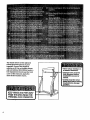
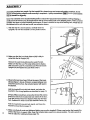
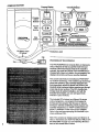
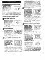
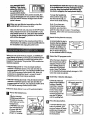
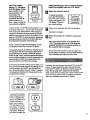
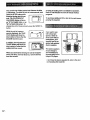
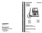
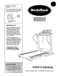
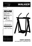
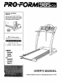
PRO.FORM
Model No. 831.298301
Serial No.
Find the serial number in the location
shown below. Write the serial number
in the space above for reference.
Sedal
Number
Decal
LIBRARY:
Received,
Copied
Entered ,
LIS._.__..
Received_
Scanned_
Batch# _
USER'S MANUAL
SEARS, ROEBUCK
AND CO., HOFFMAN ESTATES, IL 60179
PRO' ORM
TABLE OF CONTENTS
IMPORTANT PRECAUTIONS ......
...........................................................
BEFORE YOU BEGIN .......................................................................
ASSEMBLY ...............................................................................
OPERATION AND ADJUSTMENT
.............................................................
HOW TO FOLD AND MOVE THE TREADMILL
..................................................
MAINTENANCE AND TROUBLE-SHOOTING
....................
_ ..................
CONDITIONING GUIDELINES ...............................................................
PART LIST ooo _ *oo..°*.
.................................
•
•
o_..°.
•
•
ORDERING REPLACEMENT PARTS ..................................................
FULL 90-DAY WARRANTY ...........................................................
Note: An EXPLODED DRAWING is attached In the center of this manual.
2
•
•
•
3
5
6
7
13
............
14
16
18
•
Back Cover
Back Cover
IMPORTANT
PRECAUTIONS
The decals shown at the right and
below have been placed on your
treadmill. If one of the decals is
missing, or if it is not legible, please
call our toll-free HELPLINE to order a
free replacement decal (see the back
cover of this manual). Apply the
decal in the location shown.
Never allow children on
or around treadmill.
Storage latch must be
fully engaged before
treadmill is moved or
stored.
Incline must be set at
lowest level before folding
treadmill into storage
position.
KEEPHANDSANDFEETAWAY
FROMTHISAREAWHILETHE
TRE._DMILL
IS INOPERATION.
4
BEFORE YOU BEGIN
Congratulations for selecting the innovative PROFORM =
985 CD treadmill, The 985 CD treadmill features revo.utionary CD COACH technology and an impressive
array of other features to help you get the most from
every workout. And when you're not exercising, the
unique 985 CD treedmlli can be folded up, requiring
less than half the floor space of other treadmills.
Monday through Saturday, 7 a.m. until 7 p.m. Central
Time (excluding holidays). To help us assist you,
please note the product model number and serial hum*
ber before calling. The model number of the treadmill
is 831.298301. The sedal number can be found on a
decal attached to the treadmill (see the front cover of
this manual for the location).
For your benefit, read this manual carefully before
using the treadmill. If you have additional questions,
please call our toll-free HELPLINE at 1-800-736-6879,
Before reading further, please review the drawing
below and familiarize yourself with the parts that are
labeled.
CD Case Holder
Book Holder
Water Bottle
Holder (Bottle
not included)
Accessory Tray
Storage Latch
Handrails
Key/Clip
LEFT SIDE
Walking
RIGHTSIDE
On/Off Switch
Circuit
Breaker
Foot RailsWheel
Power
Cerd
Cushioned Walking Platform
Rear Roller•
Adjustment Bolts
5
ASSEMBLY
Assembly requires two people. Set the treadmill In a cleared area and remove all paddng materials. Do not
dispose of the packing materials until assembly Is completed. A phillips screwdriver (_
(not included)
rnay be needed for a_embly.
Note: The underside of the treadmiit walking belt Is coated with high-performance lubdcant. Dudng shipping, a
small amount of lubricant may be transferred to the top of the walking belt or the shipping carton. This is a normal
condition and does not affect treadmill performance. If there is lubricant on top of the walking belt, simply wipe off
the lubdcent with a soft cloth and a mild, non-abrasive cleaner.
1. With the help of a second person, carefully raise the
Updghts (15) unt=l the treadmill is in the position shown.
120
2. Make sure that the Lock Knob Sleeve (93) Is fully inserted into the left Upright (15).
2
Remove the Look Knob (92) from the Look Pin (97).
Make sure that the Look Pin Collar (95) and the Spring
(94) are on the Look Pin. Insert the Lock Pin into the left
Updght (15) and tighten the Look Knob onto it.
92
93
3. Obsewe the two Rear Feet (120) at the rear of the treadmill (see figure I above). If there Is a Space between one
of the Feet and the floor, the included spacer will need to
be attached.
3
Hold the treadmill firmly with botl_ hands, and raise the
treadmUl to the storage position as described on page 13.
Using a phillips scrawddver, remove the Screw (75) and the
RealLF.oot (120) from the side that was raised off the floor.
Snap the _rovided Rear Foot Spacer (102) onto the Rear
Foot. Reattach the Rear Foot to the treadmill Frame (79).
,oii/d//
l
Hold the treadmill firmly with both hands, and lower the
treadmill as described on page 13.
6
4. Make sure that all parts are tightened before you use the treadmill. Place a mat under the treadmill to
protect the floor or carpet. Note: Keep the included allen wrench in a secure location. The allen wrench is
used to adjust the walking belt (see page t5).
OPERATION
THE PERFORMANT
AND ADJUSTMENT
LUBE TM WALKING BELT
Your treadmill features a walking belt coated with
PERFORMANT LUBE TM, a high-performance lubricant.
IMPORTANT: Never apply silicene spray or other
substances to the walking belt or the walking platform. Such substances will detedorate the walking
belt and cause excessive wear.
This product is for use on a nominal 120-volt circuit,
end has a grounding plug that looks like the plug Illustrated In drawing 1 below. A temporary adapter that
looks like the adapter illustrated In drawing 2 may be
used to connect the surge suppressor to a 2-pole
receptacle as shown In drawing 2 if a propedy
grounded outlet Is not available.
HOW TO PLUG IN THE POWER CORD
,._----Grounded
_.l
Outlet Box
_SurgeSupp
ii
ressor
Ground,ngP,n
Grounded Outlet
firounding
Plug"_
2
Groueded Outlet Box
Your treadmill, like any other type of sophisticated
electronic equipment, can be seriously damaged by
sudden voltage changes in your home's power.
Voltage surges, spikes, and noise intederenca can
result from weather conditions or from other appliances
being tumed on or off. To decrease the possibility of
your treadmill being damaged, always use a surge
suppressor with your treadmill (see drawing 1 at
the right).
Surge suppressors are sold at most hardware stores
and department stores. Use only a single-outlet surge
suppressor that Is UL 1;_-49listed as a transient voltage
surge suppressor (TVSS). The surge suppressor must
have a UL suppressed voltage rating of 400 volts or
less and a minimum surge dissipation of 450 Joules.
The surge suppressor must be electrically rated for
120 volts AC and 15 amps.
This product must be grounded. If it should malfunction or break down, grounding provides a path of least
resistance for electdc current to reduce the _isk of electric shock. This product Is equipped with a cord having
an equipment-grounding conductor and a grounding
plug. Plug the power cord into a surge suppressor,
and plug the surge suppressor into an appropriate
outlet that is properly installed and grounded in
accordance with all local codes and ordinances.
tar
Surge Suppressor
Met ,Screw
The temporary adapter should be used only until a
properly grounded outlet (drawing 1) can be installed
by a qualified electrician.
The green-colored dgld ear, lug, or the like extending
from the adapter must be connected to a permanent
ground such as a properly grounded outlet box cover.
Whenever the adapter Is used it must be held In place
by a metal screw. Some 2-pole receptacle outlet box
covers are not grounded. Contact a qualified electrician to determine if the outlet box cover is
grounded before using an adapter.
7
CONSOLEDIAGRAM
DL y
Consoidis ;lays
Program
Select
ButtonsPause/
Bu_ons
PRO_ORA4 ...
\
\
Lift here to open
CD
The PROFORM ° 985 CD console offers an impressive
array of features to help you get the most from your
workouts. When the manual modeof the console is
selected, the speed and incline of the treadmill can be
changed with a touch of a button. As you exercise, four
displays will provide continuous exercise feedback.
The console also features revolutionary PROFORM"
CD COACH technology. This breakthrough technology
allows the console to play specially-designed CD's
that lnterectively edjust the speed and incline of the
treadmill while a personal trainer coaches you through
every step of your workout. The CD's include highenergy music for added motivaUon. And with the
included hand weights, you can add upper-body
exercise to your workouts.
The included CD's feature two different 30-minute
workout programs---one program that tar'getsf_.tburning and one program that focuses on interval
training for aerobic conditioning. Each program was
specially designed by Our AFA TM certified personal
trainer. A selection of other CD's is also available.
Refer to the card accompanying this treadmill to purchase additional CD's.
8
Note: The console can display speed and distance in
miles or kilometers (see HOW TO SELECT MILES OR
KILOMETERS on page 12). For simplicity, all instructions in this manual refer to miles.
To stop the walking belt, press the STOP button.
The four displays will pause and the TIME/PACE
Before using the console, make sure that the power
cord is prepedy plugged In.
'See HOW TO PLUG iN
THE POWER CORD on
page 7.) In addition, make
sure that the on/off switch,
Position
located near the power
cord, is in the on position.
OnJ
When you are ready to begin exercising, step onto the
foot rails of the treadmill. Find the clip attached to the
key and slide the dip onto the waistband of your clothing.
Follow _
U
steps below to operate the console.
Insert the key into the console.
A moment after the key is
I'-__
_1
inserted, the four displays
and the manual indicator
will light. In addition, a
number will appear in the
CD display for five seconds. This number indicates the current volume setring of the CD player.
B
Select the manual mode.
When the key is inserted,
the manual mode will automatically be selected.
If you have selected the
CD program mode,
press the SELECT
MODE button to select the manual mode.
_1
Press the SPEED Z_ button to start the walking
belt.
A moment after the button is pressed, the walking belt will begin to
move at 1.0 mph. Hold
the handrails and begin
walking.
As you exemise, change the speed of the walking
belt as desired by pressing the SPEED buttons.
Each time one of the buttons is pressed, the ._.
speed will change by 0.1 mph. If the buttons ar_
held down, the speed will change in increments of
0.5 mph. The speed range is 0.5 mph to 10.0 mph.
dtsplay _111begin to flesh. To restart the walking
belt, press the SPEED A button. To stop the walkIng belt and reset the displays, press the STOP
button, remove the key, and then reinsert the key.
Adi'ust the Incline as desired.
To vary the intensity of
your exercise, change
the incline of the treadmill as desired by pressing the INCLINE buttons.
Each time one of the
buttons is pressed, the
incline will change by 0.5%. The incline range is
1.5% to 10%. Note: When one of the INCLINE buttons is pressed, the INCLINE/DISTANCE
display will show the incline setting for seven
seconds. After the buttons are pressed, it may
take a moment for the treadmill to reach the selected incline setting.
Follow your progress with the four displays.
TIME/PACE display-This display shows the
elapsed time and your
current pace (pace is
measured in minutes per i
mi/e). Every seven secends, the display will change from one number to
the other. The PACE indicator will I!ght when your
pace Is shown.
SPEED displaymThis
display shows the speed
of the walking belt, in
miles per hour or kilometers per hour. (See HOW
TO SELECT MILES OR
KILOMETERS on page 12.)
CALORIES/FAT-CALORIES display--This display shows the numbers
of calories and fat catodes you have burned
(see FAT BURNING on
page 16 for an explanation of fat calodes). Every
seven seconds, the display will change from one
number to the other. The FAT CALS indica!or will
light when the number of fat calories is shown.
the headphones while the key Is in the console,
If the headphones become unplugged duflng
exercise, atop the treaIfroill end remove the
key before plugging the headphones back In.
shows the d'mtance "J_at
the walking belt has
moved and the Incfine
r_
level of the treadmill. Every seven seconds, the
display yell change from one number to the other.
The DISTANCE indicator will light when the distance Is shown.
To keep the headphone
wire out of the way, slide
the wire Into the clip, as
shown in the inset drawing.
wllen you are finished exercising,
walking belt and remove the key.
Clip
Note: I.fyou have purchased optional stereo
speakers, you may disregard this step and go to step 2. To purchase
speakers, refer to the card accompanying this
treadmill.
stop the
Step onto the foot roils and press the STOP button.
Next, change the incline of the treadmill to 1.5%.
The incline must be at 1.5% when the treadmill
is folded to the storage position or the treadroill will be damaged.
E!
Insert the key into the console.
Remove the key from the console and put it in a
secure place. In addition, move the on/off switch to
the off position and unplug the power cord.
A moment after the key is
inserted, the four d'mplays
and the manual Indicator
Will light. In addition, the
current volume setting of
the CD player will appear
fbr five seconds In the CD display.
When you use a CO workout program, a certified personsl trainer will guide you th.roughyour workout as the
CD Intemctively controls the speed and incline of the
treadmill. The included =Rhythm Mix" CD's contain two
workout programs:
Select the CD program mode.
When the key is inserted,
the manual mode will be
selected. Press the SELECT MODE button to
• Fat Burning (Level 1)--This 30-rninute workout
reaches a maximum speed of 4.2 mph and has an
average speed of 3.4 mph. The maximum Incline level
is 9% and the average incline level is 3%. Note: All
programs are designated level 1 or level 2; level 2
select the CD program
mode. Note: The incline
of the treadmill will automatically change to 1.5%
when this mode is selected.
programs provide more intense workouts.
B
• Interval Training (Level 2)----This 30--minute workout
reaches a maximum speed of 6.0 mph and has an
average speed of 3.9 mph. The maximum incline level
is 8% and the average incline level is 3.5%.
Follow the steps below to use a CDworkout
B
Put on the headphones.
PIvg the included
hea.dphones fully into
• the jacl<on the console. Next, put on the
headphones.
l0
program.
CAUTION: Use only
the included headphones with the
console. Do not
plug in or unplug
Headphone
Jack
Insert Disc I into the CD player.
Lift the lid of the CD
player in the Indicated
location, Carefully
insert Disc I into the
CD player and close
the lid. Note: Lifting
the lid during a CD
workout program will
stop the CD player
and the walking belt.
i
Press the play button.
button is pressed, your
personal trainer will begin
guiding you through your
workout. Simply follow
the instructions.
Lift here to open the
CD
WhenDisc1 begins
playing,a "1"willappear
IntheCDdisplay.Dudng
trackI of Disc1,your
personal
trainerwill
demonstrate
CD
COACHtechnology.
CAUTION:Besureto
listento trackI on
DiscI beforeusingthe
two workoutprograms.
walking belt wal begin to move. To stop the program
befora It is completed, press the STOP button.
[]
Track 1 on Disc 2 is the Interval program. To use
this program, insert Disc 2 into the CD player.
Dudng each program, an electronic'chirping=sound
will alert you when the speed and/or inclineof the
treadmill is about to change. CAUTION: Always
listen for the =chirp" and be prepared for speed
and/or incline changes. In some Instances, the
speed and/or incline will change before the
personal trainer describes the change.
If the speed and incline settings are too high or too
low, you can manually override the settings at any
time by pressing the SPEED and INCLINE buttons. However, when the next =chirp" is heard,
the speed and incline will change back to the
programmed settings.
! sl
LL
To us,
II ev
press the VOLUME buttons. The current volume
setting will appear in the
CD display. There are
ten volume settings.
Program
Select
Buttons
Track 2 on Disc i is the Fat Buming program. Track
2 will begin after track 1, and can also be selected
with the program select buttons. After a buttoq is
pressed, an indicator wiU move around the CD display'for a few seconds and then the number'2" will
appear. CAUTION: To scan forward or backward
during a program, stand on the foot rails and
hold down the program select buttons.
Adjust the volume If desired.
B
Follow your progress with the four displays.
See step 5 on page 9.
r_
When the program is completed, remove the
key.
Make sure that the incline of the treadmill is at
1.5%. The incline must be at 1,5% when the
treadmill is folded to the storage position or
the treadmill will be damaged.
Remove the key from the console and put it in a
secure place. In addition, move the on/off switch to
the off position and unplug the power cord.
If desired, you can play your own music CD's in the CD
player. To play music CD's, select the manual mode
(see HOW TO USE THE MANUAL MODE on page 9).
Note: Do not play CD's longer than 55 minutes.
While music CD's are playing, the number of the current
track will not be shown in the CD display; an indicator
will move repeatedly around the CD display.
=o_
INC/JNE ! D|ST_
II
2/ 2/I1_._,
To pause the program,
press the pause button.
The four displays will
pause, the TIME/PACE
display will begin to
flash, and the letters
=PA" will appear in the
CD display. To restart
the program, press the
play button. When the
next chirp is heard, the
11
Theconsolecandisplayspeedanddistancein miles
or kilometers. To check the unit of measuremenL hold
down the STOP button _hile
Inserting the key into the console. The CALORIES/FAT
CALOR!ES display will show
an "E,=for English miles, or an
=M,=for Metric kilometers. To
A vadety of exciting CD's Is available for purchase.
Each CD set Includes two new 30-minute workout
programs.
To purchase additional CD's, refer to the card aCcompanying this treadmill.
change the unit of measurement, press the SPEED/k
button.
Oetheunofmeasure
I' ;ll
ment is displayed_ the TIME/
PACE display will show the
total number of hours that the
treadmill has been used.
total number of miles that the
In add'Cdon,the
TANCE
display
will
show the
walking
belt hasINCUNF_JDISmoved.
_nME
_
O
If you want to use
CD workout pro_
grams or listen to
music CO's without
headphones, your
treadmill can be upgraded with optional
stereo speakers.
I
_l_-==_=o_
_=_
ff._
When you are finished viewing the unit of measurement, total time, and total distance, remove the key
from the console.
The stf_raospeakers
• mount directJyto
your treadmill and
COnnecteasily to the
integral CD player.
b purchase the stereospeaker kit, referto thecard
ccompanyingthis treadmill.
12%.
HOW TO FOLD AND MOVE THE TREADMILL
HOW TO FOLD THE TREADMILL
FOR STORAGE
Before folding the treadmill, adjust the Incline to the
lowest position. If this is not done, the treadmill may be permanently damaged. Next, unplug the power cord. CAUTION: You must be able to safely lift 45 pounds (20 kg) In
order to raise, lower, or move the treadmill.
1. Hold the treadmill with your hands in the locations shown at
the right. CAUTION: To decrease the possibility of injury,
bend your legs and keep your back straight. As you
raise the treadmill, make sure to lift with your legs rather
than _our back. Raise the treadmill about halfway to the
vertk_al position.
2.
Move your right hand to the position shown and hold the
treadmill firmly. Using your left hand, pull the latch knob to
the left and hold it. Raise the treadmill until the latch pin Is
aligned with the hole in the catch. Insert the latch pin into
the catch. Make sure that the latch pin is fully Inserted
into the catch.
2
To protect the floor or carpet from damage, place a mat
under the treadmill. Keep the treadmill out of
direct sunlight. Do not leave the treadmill in the Storage
position In temperatures above 85 ° Fahrenheit.
HOW TO MOVE THE TREADMILL
Before moving the treadmill, convert the treadmill to the storage
position as described above. Make sure that the latch pin is
fully inserted into the catch.
1. Hold the treadmill as.shown and place one foot against a
wheel. Do not hold or push on the book holder or the
book holder may be damaged.
2. Tilt the treadmill back until it roils freely on the front wheals;
Carefully move the treadmill to the desired location. Never
move the treadmill without tipping it back. To reduce
the risk of injury, use extreme caution while moving the
treadmill. Do not attempt to move the treadmill over an
uneven surface.
3. Place one foot on the base,and carefully lower the treadmill
until it is resting in the storage position.
HOW TO LOWER THE TREADMILL
E_J----J"'_-FrentWheels J
FOR USE
1. Refer to drawing 2 above. Hold the treadmill with your right hand as shown. Using your left hand, pull the latch
knob to the left and hold it. Pivot the treadmill down until the frame is past the pin. Slowly release the latch knob.
2. Refer to drawing 1. Hold the treadmill firmly with both hands, and lower the treadmill to the floor. CAUTION:
• To decrease the possibility of Injury, bend your legs and keep your back straight.
13
•MAINTENANCE AND TROUBLE-SHOOTING
Most treadmill problems ca n be solved by following the simple steps below. Rnd the symptom that
applies, and follow the steps listed. If further assistance Is needed, call our toll-free HELPLINE at
1-800-736-6879, Monday through Saturday, 7 s.m. until 7 p.m. Central Time (excluding holidays)
_-
1. SYMPTOM:THE
,°
•
°
POWER DOES NOT TURN ON
a. Make sure that the power cord is plugged into a surge suppressor, and that the surge suppressor is plugged
into a properly grounded outlet (see page 7). Use only a single-outlet surge suppressor that is UL 1449
r=stedas a transient voltage surge suppressor (TVSS). The surge suppressor must have a UL suppressed
voltage rating of 400 volts or less and a minimum surge dissipation of 450 joules. The surge suppressor
must be electdcaUy rated for 120 volts AC and 15 amps.
b. After the power cord has been plugged in, make sure that the key is inserted into the console as far as it will
go. See step I on page 9.
c. Check the circuit breaker located on the treadmill near the
power cord. If the switch protrudes as shown, the circuit
breaker has tripped. To reset the circuit breaker, wait for five
minutes and then press the switch back in.
c
Tripped
Reset
d. Check the on/off switch located on the treadmill near the
power cord. The switch must be in the on position.
on j
d
Position
2. SYMPTOM: THE POWER TuRNs
OFF DURING USE
a. Check the circuit breaker located on the treadmill frame near the power cord (see 1, c. above). If the circuit
breaker has tdpped, wait for five minutes and then press the switch back in.
b. Make sure that the power cord is plugged in.
c. Remove the key from the console. Reinsert the key fully into the console. See step I on page 9.
d. Make sure that the on/off switch is in the on position.
s
e. ff the treadmill still will not run, please call our toU-free HELPLINE.
3. SYMPTOM: THE DISPLAYS OF THE CONSOLE
DO NOT FUNCTION
a. Remove the key from the console and UNPLUG THE POWER
CORD. Remove the screws from the hood. Carefully remove the
hood. Locate the Reed Switch-(26) and the Magnet (107) on the
left side of the Pulley (12). Turn the Pulley until the Magnet is
aligned with the Reed Switch. Make sure that the gap between
th_ Magnet and the Reed Switch is about 1/8". If necessa_,
Io_._.enthe Reed Switch Screw (121) and movetheReed Switch
slightly.'Fletighten the Screw. Re-attach the hood, and run the
treadmi!Uor a few minutes to check for a correct speed reading.
4. SYMPTOM: souND
PROPERLY
I
I
1/8"-121_
Top
View
I
b
IS HEARD IN ONLY ONE SIDE OF THE HEADPHONES
a. Make sure that the headphones are fully inserted into the headphone jack on the console.
5.SYMPTOM:Thewalkingbelt
slows when walked on
a. Use only a UL-tisted surge protector, rated at 15 amps, with a 14-gauge cord of five feet or less In length.
b. If the walking belt is ovedightened, treadmill performance may
decrease and the walking belt may be permanently damaged.
Remove the key and UNPLUG THE POWER CORD. Using the
allen wrench, tum both rear roller adjustment bolts countemlockwise, 1/4 of a turn. When the walking belt Is propedy tightened,
you should be able to lift each side of the walking belt 3 to 4
inches off the walking platform. Be careful to keep the walking
belt centered. PJug in the power cord, insert the key and run the
treadmill for a few minutes. Repeat until the walking belt is properly tightened.
b
Rear Roller Adjustment Bolts
c. If the walking belt still slows when walked on, please call our tollfre_'_HELPUNE.
6. SYMPTOM:
The walking belt Is off-center
a. If the walking bolt has shifted to the left, first remove the key and
UNPLUG THE POWER CORD. Using the allen wrench, tum the
• left rear roller adjustment bolt clockwise, and the dght bolt counterclockwise, 1/4 of a turn each. Be careful not to overtighten the
walking belt. Plug in the power cord, insert the key and run the
treadmill for a few minutes. Repeat until the walking belt is centered.
b. If the walking belt has shifted to the right, first remove the key
and UNPLUG THE POWER CORD. Using the allen wrench, turn
the left rear roller adjustment bolt counterclockwIse, and the right
bolt clockwise, 1/4 of a tum each. Be careful not to overtighten
the walking belt. Plug in the power cord, insert the key and run
the treadmill for a few minutes. Repeat until the walking belt is
centered.
7. SYMPTOM:
The walking belt slips when walked on
a. If the walking belt slips when walked on, first remove the key and
UNPLUG THE POWER CORD. Using the allen wrench., tum
both rear roller adjustment bolts clockwise, 1/4 of a turn. When
the walking belt is correctly tightened, you should be able to lift
each side of the walking belt 3 to 4 inches off the walking platform. Be careful to keep the walking belt centered. Plug in the
power cord, Insert the key and carefully walk on the treadmill for
a few minutes. Repeat until the walking belt is propedy tightened.
15
-CONDITIONING
GUIDELINES
Aerobic Exercise
The following guidelines will he p you to plan your exercise program. For more information about exercise,
consult your physician or obtain a reputable book.
EXERCISE
INTENSITY
Whether your goal is to bum fat or to strengthen your
cardiovascular system, the key to achieving the desired
results is to exercise with the proper Intensity. The
proper Intensity level can be found by using your heart
rate as a guide. The chart at the bottom of this page
shows recommended heart rates for fat burning and
aerobic exercise.
To find the proper heart rate for you, first find your age
at the top of the chart (ages are rounded off to the
nearest ten years). Next, find the three numbers below
your age. The three numbers define your "training
zone." The lowest two numbers are recommended
heart rates for fat burning, and the highest number is
the recommended heart rate for aerobic exercise.
If your goal is to strengthen your cardiovascular system,
your exercise must be "aerobic." Aerobic exercise is
activity that requires large amounts of oxygen for prolonged pededs of time. This Increases the demand on
the heart to pump blood to the muscles, and on the
lungs to oxygenate the blood. For aerobic exercise,
adjust the speed and Incline until your heart rate is near
the highest number in your training zone.
HOW TO MEASURE YOU HEART RATE
To measure your heart
rate, stop exercising
and place two fingers
on your wdst as
shown. Take a sixsecond heartbeat
count_ and multiply the
result by ten to find
your heart rate. (A sixsecof_d count Is used because your heart rate drops
quickly when you stop exercising.) If your heart rate is
too high or too low, adjust the speed or incline of the
LreadmUl accordingly.
WORKOUT
GUIDEUNES
Each workout should include three parts: (1) a warmbp, (2) training zone exercise, and (3) a cool-down.
Fat Bumlng
Warming Up
To bum fat effectively, you must exercise at a relatively
low intensity level for a sustained period of time. Dudng
the first few minutes of exercise, your body uses easily
accessible carbohydrate calories for energy. Only after
the first few minutes does your body begin to use stored
fat ca/cries for energy. If yoiJrgoal is to bum fat, adjust
the speed and Incline of the treadmill until your heart
Begin each workout with five to ten minutes of stretching and light exercise to warm up. A proper warm-up
increases your body temperature, heart rate and circulation in preparation for exercise.
Training Zone Exercise
rate is near the lowest number in your tra!ning zone.
For maximum fat buming, adjust the_speed and incline
until your heart rate is near the middle number in your
training zone.
I
16
.:
After warming up, increase the Intensity of your exercise until your head rate is in your training zone for 20
to 30 minutes. Breathe regularly and deeply as you
exercise_never hold your breath.
AGE 120130140150160!701
801
"°
Cooling Down
Exercise Frequency
End each workout with five to ten minutes of stretching
to cool down. This will develop muscle flexibility and
will help to prevent post-exercise problems.
To maintain or Improve your condition, complete three
workouts each week, with at least one day of rest between workouts. After a few months, you may complete up to five workouts each week if desired.
The key to success is to make exercise a regular and
enjoyable part of your everyday life.
SUGGESTED
STRETCHES
The correct form for several basic stretches is shown in the
drawings at the right. Move slowly as you stretch--_never
bounce:*
1. Toe Touch Stretch
Stand with your knees bent slightly and slowly bend forward
from your hips. Allow your back and shoulders to relax as you
reach down toward your toes as far as possible. Hold for 15
counts, then relax. Repeat 3 times. Stretches: Hamstrings,
back of knees end back.
2
2. Hamstring Stretch
Sit with one leg extended. Bring the sole of the opposite foot
toward you and rest it against the inner thigh of your extended
leg. Reach toward your toes as far as possible. Hold for 15
counts, then relax. Repeat 3 times for both legs. Stretches:
Hamstrings, lower back and groin.
3
3. Calf/Achtiles Stretch
With one leg in front of the other, reach forward and place your
hands against a wall. Keep your back leg straight and your
back foot fiat on the floq.(.Bend your front leg, lean forward and
move your hips toward the wall Hold for 15 counts then _'elax.
Repeat 3 times for both legs. To cause further stretching of the
achilles tendons, bend your back leg as well. Stretches:
Calves, achilles tendons and ankles.
4. Quadriceps
4
Stretch
With one hand against a wall for balance, reach back and
grasp one foot with your other hand. Bring your heel as Close
to your buttocks as possible. Hold for 15 counts, then relax.
Repeat 3 times for both legs. Stretches: Quadriceps and hip
muscles.
5. Inner Thigh Stretch
Sit with the soles of your feet together and your knees outward.
Pull your feet toward your groin area as far as possible. Hold
for 15 counts, then relax. Repeat 3 times. Stretches:
Quaddceps and hip muscles.
17
•PART LIST--Model
No. 831.298301
RO599A
To identify pads listed below, refer to the EXPLODED DRAWING attached In the center of this manual.
Key
No. Qty.
Description
1
2
Center Track
2
2
Foot Rail
3
1
Left Foot Rail Cap
4
1
Front Roller Adjustment Nut
5
4
Isolator
6
4
Bumper
7
4
Platform Screw
8
1
Walking Platform
9
2
Frame Pivot Bolt
10
2
Frame Pivot Spacer
11
1
Walking Belt
12
1
Front RoUer/Pullay
13
16
Small Screw
14
1
Motor Belt
15
1
Updght/Base
16
1
Incline Frame
17
1
Hood Bracket (long)
18
1
Front Roller/Pulley
19
1
50" Power Wire Harness
2O
1
Motor Tension Spacer
21
8
Nut
22
1
lift Motor Shield
23
2
Incline Motor Bolt
24
1
Alien Wrench
25
1
Incline Motor"
26
1
Reed Switch
27
4
Jack Screw
28
1
Upright Ground Screw
29
1
UpdghUBase Ground Wire
3O
2
Wheel Bolt
31
2
Front Wheel
32
2
Hood Anchor
33
4
Motor Nut
34
1
Pulley/Flywheel/pan
35
1
Motor
36
4
Motor Bolt
37
4
Motor Isolator
38
1
Motor Tension Bolt 39
1
Console Ground Screw
40
2
Incline Pivot Bolt
41
_--:1 Motor Hood
42 '-_
Incline Motor Shield
43
2
"-Incline Pivot Washer
44
3
"_Adj.Washer
45*
1
Motor/pulley/FlyJFan
46
1
Front Roller Adj. Bolt
47
1
Transformer
48
1
Electronics Bracket
49
1
Controller
5O
1
Electronics Shield
18_,.
51
1
Power Supply
Key
No.
52
53
54
55
56
57
58
59
60
Qty,
Description
4
1
1
1
1
1
Plastic Stand-off
Power Cord
Grommet
On/Off Switch
Circuit Breaker
Outlet Bracket
2
2
1
Motor Tension Bushing
Belt Guide
Shock
61
1
62
1
22
63
64
1
65
6
66 " 1
67
2
Front Belly Pan
Right Foot Rail Cap
Plastic Fastener
Console Base
3/4" Console Screw
Crossbar Handrail
Rear Isolator
68
69"
70
Belly Pan
Console Plate Screw
Hood Screw
Key/Clip
Cap Screw
Rear Endcap
Optional Speaker Kit
Bumper Screw/Belly Pan Screw
Rear Roller Adj. Bolt
Caution Decal
Latch Decal
Frame
Rear Dock Screw
Console
Latch Catch
Rear Roller
Console Spring
Cable Tie
Cable Tie Screw/Shield Screw
Cable Tie Clamp
8" Cable Tie
4" Cable Tie
Upright Wire Harness
Handrail Foam
Lock Knob
I_ock Knob Sleeve
71
72
73
74**
75
76
77
78
79
80
81
82
83
84
85
86
87
88
89
90
91
92
93
94
95
96
97
98
99
100
101
102
1
4
4
1
2
1
1
10
2
2
1
1
4
1
1
1
1
2
11
2
2
5
1
2
1
1
1
1
Spring
Lock Pin Collar
1'
1
1
1
4
1
Pin Clip
Lock Pin
CD Console
CD Player
CD Fastener
CD Plate
2
Rear Endcap Spacer
Key
No.
Qty.
103
4
104
10
105
4
106
1
107
1
108
1
109"
1
110
1
111
1
112
1
113
1
114
2
115
1
116 "I
117
2
118
2
119
1
120
2
121
1
122
1
123
1
124
2
125
1
126
1
127
1
128
2
Description
CD Isolator
Console Fastener
Upright Endcap
Upright Grommet
Magnet
Console Base Back
Console Assembly
Reed Switch Clip
Incline Motor Spacer
Optic Disk
Optic Switch Nut
Optic Switch Washer
Optic Switch Bolt
Optic Switch
21bs. Hand Weight
Roller Guard
Head Phone
Rear Foot
Ground Wire
Ground Wire Screw
Incline Stop Bracket
Crossbar Bolt
26" Wire Harness
19" Stereo Wire Harness
20" Wire Harness
Crossbar Plastic Washer
Key
No. Qty.
Descdptlon
129
130
131
132
133
134
135
136
#
#
#
#
#
#
#
2
8
1
1
1
1
2
2
1
1
1
1
1
1
1
Rhythm Mix CD Set
Isolator Screw
Motor Isolator
Console Plate
50" Wire Harness
4" Wire Harness
Crossbar Washer
Crossbar Plastic Washer
12" Blue Pigtail Wire
8" Blue Wire, 2 Female
4" Blue Wire, Male/Female
8" Green Wire, Female/Ring
6" Green Wire, 2 Ring
8" Black Wire, 2 Female
4 =Black/White Wire
#
#
#
#
#
1
2
1
1
1
12" White Pigtail Wire
8" White Wire, 2 Female
9" Wire Harness
8" Wire Harness
User's Manual
.
# These parts are not illustrated
* Includes all parts shown in the box
** For more information about the optional speaker kit,
see page 12.
Specifications are subject to change without notice. For information about ordering replacement parts, see the
back cover of this manual.
19
EXPLODED
39
23
DRAWING--Model
No. 831.298301
Ros_gA
25
111
JJ"
112
21
"-
21
21
10
2
115
9
8
5
82
11
\
130
36
18
80_
2O
83
118
86
REMOVE THIS EXPLODED DRAWING FROM THE
USER'S MANUAL. SAVE THIS EXPLODED DRAWING
FOR FUTURE REFERENCE.
76
To identify the parts shown on this exploded drawing, refer to the PART LIST on pages 18 and 19 of
the USER'S MANUAL.
76
44
73
EXPLODED
DRAWINGmModel
No. 831.298301
Ro599A
71
132
124
117
128
'__127
98
105
135
I
i
27
91
i
93
92
106
66
95
101
i
i
10"
64
97
i
i
I
128
91
70
96
6,3
70
135
124
I
43
41
i
70
|
21
27
30
86
22
29
24
87
t88
llllf
The model number and serial number of your PROFORM. 985 CD
treadmill are listed on a decal attached to the frame. See the front
cbver of this manual to find the location of the decal.
Model No. 831.298301
QUESTIONS?
All replacement parts are available for immediate purchese or
special order when you visit your nearest SEARS Service Center.
To request service or to order parts by telephone, call the toll-free
numbers listed at the left.
If you find that:
• you need help assembling or
operating the PROFORM* 985
CD treadmill treadmill
• a part is missing
When requesting help or service, or ordering parts, please be
prepared to provide the following information:
• The NAME OF THE PRODUCT (PROFORM ° 985 CD treadmill)
• or you need to schedule repair
service
call our toll-free HELPUNE
1-800-736-6879
Monday--Saturday, 7 am-7 pm
Central Time (excluding holidays)
• The MODF_J_NUMBER OF THE PRODUCT (831.298301)
• The KEY NUMBER AND DESCRIPTION OF THE PART (see the
PART LIST on pages 18 and 19 and the EXPLODED DRAWING
attached in the center of this manual).
REPLACEMENT
PARTS
If parts become worn and need
to be replaced, call the following
toll-free number
1-800-FON-PART
(1-800-366-7278)
FULL 90 DAY WARRANTY
For 90 days from the date of purchase, if failure occurs due to defect In material or workmanship in this
SEARS TREADMILL EXERCISER. contact the nearest SEARS Service Center throughout the United
States and SEARS will repair or replace the TREADMILL EXERCISER, free of charge.
This wa.rrenty does not apply when the TREADMILL
poses. -
EXERCISER
is used commemially or for rental pur-
T
•
•
h=swarranty
gives you specific legal rights, and you may also have other rights which vary from state
to state.
SEARS, ROEBUCK AND CO., DEPT. 817WA, HOFFMAN
Part No. 153400 J00448-C
R0599A
ESTATES, IL 60179
Printed in USA © 1999 Sears, Roebuck and Co.