1
Operation Installation Manual
Rinnai Evacuated Tube
Split Solar Hot Water Systems
This system shall be installed in accordance with:
0DQXIDFWXUHU¶V,QVWDOODWLRQ,QVWUXFWLRQV
&XUUHQW$61=6
$OODSSOLFDEOHORFDOUXOHVDQGUHJXODWLRQVLQFOXGLQJORFDO2+6UHTXLUHPHQWV
7KLVV\VWHPPXVWEHLQVWDOOHGFRPPLVVLRQHGDQGVHUYLFHGE\DQ$XWKRULVHG3HUVRQ
All Rinnai gas products
are A.G.A. certified.
W169
SAI Global
Issue
1
7KHFROOHFWRUIORZDQGUHWXUQSLSHZRUNVKRXOGEHPPFRSSHUWXEHRU
DOWHUQDWLYHWXEHVXSSOLHGE\5LQQDL3ODVWLFSLSHPXVWQRWEHXVHGDVLWLVQRW
VXLWHGWRWKHKLJKZDWHUWHPSHUDWXUHVDQGSUHVVXUHVWKDWPD\RFFXU
&HUWDLQV\VWHPVPD\UHTXLUHVRPHFRPSRQHQWVWREHVXSSOLHGE\WKHLQVWDOOHU
12768,7$%/($6$322/2563$+($7(5
AS 2712
Lic No.1849
SAI Global
This manual is applicable to:
Rinnai ‘Prestige’ ® Stainless Steel,Split, Evacuated Tube Solar Hot Water Systems;
Rinnai ‘Sunmaster’ ® Glass Lined, Split, Evacuated Tube Solar Hot Water Systems; and
‘Equinox’ ® Stainless Steel and Glass Lined, Split, Evacuated Tube Solar Hot Water Systems.
7KLVPDQXDOPXVWEHXVHGLQSODFHRIWKHVSOLWV\VWHPPDQXDOIRUÀDWSODWHFROOHFWRUVWKDWLVSURYLGHGLQ
the pump kit.
3OHDVHXVHWKDWWKHODWHVWYHUVLRQRIWKHZDUUDQW\ERRNOHWDQG67&IRUP2OGHUYHUVLRQVPD\EHLQFOXGHG
in the pump kit
Rinnai
i
EVT Split System Operation and Installation Manual
TABLE OF CONTENTS
Warnings and Important Information
1
Safety and Regulatory Information ..................................................................................................................... 1
Scald Hazards .................................................................................................................................................... 2
Operation Principle ............................................................................................................................................. 3
Safety Devices ................................................................................................................................................... 4
Excessive Discharge from Safety Devices ......................................................................................................... 4
Gas Boosters ...................................................................................................................................................... 5
Hydrogen Gas .................................................................................................................................................... 5
Water Temperature ............................................................................................................................................. 5
Turning Off the Water Heating System ............................................................................................................... 5
Turning On the Water Heating System ............................................................................................................... 5
Water Quality ...................................................................................................................................................... 6
Draining and Filling the Water Heating System .................................................................................................. 6
Maintenance and Regular Care ......................................................................................................................... 6
Servicing and Repair .......................................................................................................................................... 6
6DYHD6HUYLFH&DOO
6SHFL¿FDWLRQV
General ............................................................................................................................................................... 9
System ............................................................................................................................................................... 9
Evacuated Tube Solar Collectors ..................................................................................................................... 10
Storage Cylinders ............................................................................................................................................. 11
Gas Boosters .................................................................................................................................................... 15
,QVWDOODWLRQ$OO6\VWHPV
Regulations and Occupation Health and Safety (OH&S) ................................................................................ 16
Location - General Information ......................................................................................................................... 16
Storage Cylinder Location ................................................................................................................................ 16
Gas Booster Location ...................................................................................................................................... 17
Water Pipes ...................................................................................................................................................... 17
Water Supply .................................................................................................................................................... 17
Hot Water Delivery Temperature ...................................................................................................................... 18
Frost Protection Mode ...................................................................................................................................... 19
Valves and Fittings ........................................................................................................................................... 20
,QVWDOODWLRQ(YDFXDWHG7XEHV
Regulations and Occupation Health and Safety (OH&S) ................................................................................ 21
System Orientation and Inclination ................................................................................................................... 21
Solar Collector Roof Mounting Options ............................................................................................................ 22
Components ..................................................................................................................................................... 22
Assembly Instructions ..................................................................................................................................... 26
Rinnai
ii
EVT Split System Operation and Installation Manual
TABLE OF CONTENTS
,QVWDOODWLRQ*DV%RRVWHG6\VWHPV
Overview of System Components ................................................................................................................... 30
Gas Booster Location ....................................................................................................................................... 30
Gas Supply ....................................................................................................................................................... 30
Hot Water Delivery Temperature ...................................................................................................................... 30
System Using Rinnai SmartStart ...................................................................................................................... 31
Gas Booster Clearances .................................................................................................................................. 32
Gas Booster Mounting ...................................................................................................................................... 33
Components and Installation Diagrams ........................................................................................................... 34
Installation Procedure ....................................................................................................................................... 40
Filling the System ............................................................................................................................................. 42
Checking Solar Pump Operation ...................................................................................................................... 42
Adjusting Flow Control Valve ............................................................................................................................ 42
Pre Solar Heating Checks ................................................................................................................................ 43
Solar Heating .................................................................................................................................................... 44
Finishing the Installation ................................................................................................................................... 44
Draining Instructions ......................................................................................................................................... 44
,QVWDOODWLRQ(OHFWULF%RRVWHG6\VWHPV
Overview of System Components ................................................................................................................... 45
Electric Supply .................................................................................................................................................. 45
Hot Water Storage and Delivery Temperature .................................................................................................. 45
Installation Procedure ....................................................................................................................................... 50
Filling the System ............................................................................................................................................. 53
Checking Solar Pump Operation ...................................................................................................................... 53
Adjusting Flow Control Valve ............................................................................................................................ 53
Pre Solar Heating Checks ................................................................................................................................ 54
Auxiliary Energy Supply ................................................................................................................................... 54
Finishing the Installation ................................................................................................................................... 54
Draining Instructions ......................................................................................................................................... 54
Rinnai
iii
EVT Split System Operation and Installation Manual
WARNINGS AND IMPORTANT INFORMATION
SAFETY AND REGULATORY INFORMATION
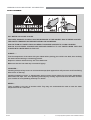
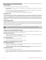
DO NOT operate this system before reading the manufacturers instructions.
WARNING
This appliance must be installed, commissioned and serviced by an authorised person in accordance
with all applicable local rules and regulations.
Access covers of water heating system components will expose 240V wiring and MUST be removed by
an authorised person.
This appliance is not intended for use by persons (including children) with reduced physical, sensory or
mental capabilities, or lack of experience and knowledge, unless they have been given supervision or
instruction concerning use of the appliance by a person responsible for their safety.
For continued safety of this appliance it must be installed, operated and maintained in accordance with
the manufacturer’s instructions.
Children should be supervised to ensure they DO NOT play with the appliance.
Any power leads from the water heater system components MUST BE plugged into an external
weatherproof electrical outlet. If the power supply cord of any water heating components is damaged, it
MUST BE replaced by an authorised person in order to avoid a hazard, using genuine replacement parts
available from Rinnai. Take care not to touch the power plugs with wet hands.
Care should be taken not to touch the pipe work as it may be HOT! The pipes between the solar collectors
and storage cylinder MUST BE copper or alternative material pipes that may be supplied by Rinnai.
Plastic pipe is NOT suited to the water temperatures and pressures that may occur in the system.
DO NOT place articles on or against this appliance.
'2127VWRUHFKHPLFDOVRUÀDPPDEOHPDWHULDOVQHDUWKLVDSSOLDQFH
DO NOT operate with collectors or covers removed from this appliance.
DO NOT activate pump unless cylinder is full of water.
1(9(5XVHDÀDPPDEOHVSUD\VXFKDVKDLUVSUD\ODFTXHUSDLQWHWFQHDUWKLVXQLWDVWKLVPD\FDXVHD
¿UH
127,&(729,&725,$1&21680(56
This appliance must be installed by a person licensed with the Plumbing Industry Commission.
Only a licensed person will have insurance protecting their workmanship.
6RPDNHVXUH\RXXVHDOLFHQVHGSHUVRQWRLQVWDOOWKLVDSSOLDQFHDQGDVNIRU\RXU&RPSOLDQFH&HUWL¿FDWH
For Further information contact the Plumbing Industry Commission on 1800 015 129.
Rinnai
1
EVT Split System Operation and Installation Manual
WARNINGS AND IMPORTANT INFORMATION
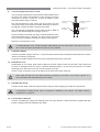
SCALD HAZARDS
+27:$7(5&$1&$86(6&$/'6
&+,/'5(1',6$%/('(/'(5/<$1'7+(,1),50$5($77+(+,*+(675,6.2)%(,1*6&$/'('
)((/:$7(57(03(5$785(%()25(%$7+,1*256+2:(5,1*
6&$/'6)520+27:$7(57$36&$15(68/7,16(9(5(,1-85,(672<281*&+,/'5(1
6&$/'6 2&&85 :+(1 &+,/'5(1 $5( (;326(' ',5(&7/< 72 +27 :$7(5 :+(1 7+(< $5(
3/$&(',172$%$7+:+,&+,6722+27
$/:$<6
7HVWWKHWHPSHUDWXUHRIWKHZDWHUZLWK\RXUHOERZEHIRUHSODFLQJ\RXUFKLOGLQWKHEDWKDOVRFDUHIXOO\
IHHOZDWHUEHIRUHEDWKLQJRUVKRZHULQJ\RXUVHOI
6XSHUYLVHFKLOGUHQZKHQHYHUWKH\DUHLQWKHEDWKURRP
0DNHVXUHWKDWWKHKRWZDWHUWDSLVWXUQHGRIIWLJKWO\
&216,'(5
,QVWDOOLQJFKLOGSURRIWDSFRYHUVRUFKLOGUHVLVWDQWWDSVERWKDSSURDFKHVZLOOSUHYHQWDVPDOOKDQGEHLQJ
able to turn on the tap).
,QVWDOOLQJ WHPSHULQJ YDOYHV RU WKHUPRVWDWLF PL[LQJ YDOYHV ZKLFK UHGXFH WKH KRW ZDWHU WHPSHUDWXUH
GHOLYHUHGWRWKHWDSV<RXUORFDOSOXPELQJDXWKRULW\PD\DOUHDG\UHTXLUHWKDWWKHVHEH¿WWHG&RQWDFW
your installer or local plumbing authority if in doubt.
1(9(5«
/HDYH D WRGGOHU LQ WKH FDUH RI DQRWKHU FKLOG 7KH\ PD\ QRW XQGHUVWDQG WKH QHHG WR KDYH WKH ZDWHU
WHPSHUDWXUHVHWDWDVDIHOHYHO
Rinnai
2
EVT Split System Operation and Installation Manual
WARNINGS AND IMPORTANT INFORMATION
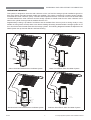
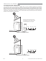
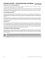
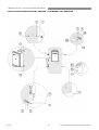
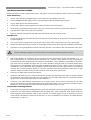
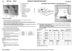
OPERATION PRINCIPLE
This system is designed to have the solar collectors on the roof and the storage cylinder installed at ground or
ÀRRUOHYHO(OHFWULFDQG*DVERRVWHGPRGHOVDUHDYDLODEOH7KHV\VWHPFRPSULVHVDKRWZDWHUVWRUDJHF\OLQGHU
evacuated tube solar collectors, pump, controller and temperature sensors. The solar control unit ensures water
circulates between the solar collectors and the storage cylinder to transfer heat from the solar collectors to the
water in the cylinder if enough heat is available from the sun.
6XSSOHPHQWDU\KHDWLQJLVSURYLGHGLILQVXI¿FLHQWKHDWLVDYDLODEOHIURPWKHVXQVXFKDVGXULQJFORXG\RUUDLQ\
weather or during winter months) either via an electric heating element(s) located inside the storage cylinder or via
an in-line Gas booster located external to the storage cylinder. The following diagrams illustrate the Split Solar Hot
Water System set up with both Electric and Gas boosting.
TO HOT WATER
OUTLETS
GAS SUPPLY
PUMP &SOLAR
CONTROL MODULE
PUMP &SOLAR
CONTROL MODULE
TO HOT WATER
OUTLETS
COLD WATER
SUPPLY
COLD WATER
SUPPLY
ELECTRIC ELEMENT
Glass Lined Gas Boosted Solar Hot Water System
Glass Lined Electric Solar Hot Water System
TO HOT WATER
OUTLETS
PUMP &SOLAR
CONTROL MODULE
GAS SUPPLY
TO HOT WATER
OUTLETS
COLD WATER
SUPPLY
PUMP & SOLAR
CONTROL MODULE
COLD WATER
SUPPLY
ELECTRIC ELEMENT
Stainless Steel Gas Boosted Solar Hot Water System
Rinnai
Stainless Steel Electric Solar Hot Water System
3
EVT Split System Operation and Installation Manual
WARNINGS AND IMPORTANT INFORMATION
SAFETY DEVICES
The water heating system is supplied with various safety devices including temperature sensors, overheat sensors
and switches and a Pressure & Temperature Relief (PTR) valve. These devices must not be tampered with or
UHPRYHG7KHZDWHUKHDWLQJV\VWHPPXVWQRWEHRSHUDWHGXQOHVVHDFKRIWKHVHGHYLFHVLV¿WWHGDQGLVLQZRUNLQJ
order.
'2127WDPSHUZLWKRUUHPRYHVDIHW\GHYLFHV
WARNING
'2127RSHUDWHWKHZDWHUKHDWHUXQOHVVDOOVDIHW\GHYLFHVDUH¿WWHGDQGLQZRUNLQJRUGHU
'2127EORFNRUVHDOWKH3759DOYHDQGGUDLQSLSH
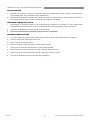
Pressure & Temperature Relief (PTR) Valve
This valve is located near the top of the water heater
and is essential for safe operation. It is normal for the
valve to release a small quantity of water through the
drain line during heating.
However, continuous leakage of water from the valve
and its drain line may indicate a problem with the
water heater.
WARNING
Tw ist cap until w ater
flow s from drain line
Lift lever until w ater
flow s from drain line
(Low er lever genlty!)
1HYHUEORFNWKHRXWOHWRIWKH375YDOYHRULW¶VGUDLQOLQHIRUDQ\UHDVRQ7KHHDVLQJJHDUPXVWEH
RSHUDWHGDWOHDVWHYHU\PRQWKVWRUHPRYHOLPHGHSRVLWVDQGYHULI\WKDWLWLVQRWEORFNHG)DLOXUH
WRGRWKLVPD\UHVXOWLQWKHZDWHUKHDWHUIDLOLQJ
,IWKHYDOYHGRHVQRWGLVFKDUJHZDWHUZKHQWKHHDVLQJJHDUOHYHULVRSHQHGRUGRHVQRWVHDODJDLQ
ZKHQWKHHDVLQJJHDULVFORVHGDWWHQGDQFHE\DQDXWKRULVHGSHUVRQPXVWEHDUUDQJHGZLWKRXW
GHOD\7KH375YDOYHLVQRWVHUYLFHDEOH
EXCESSIVE DISCHARGE FROM SAFETY DEVICES
Pressure & Temperature Relief (PTR) Valve
It is normal and desirable that this valve allows a small quantity of water to be discharged during the heating cycle.
If it discharges more than a bucket of water during a 24 hour period or discharges continuously there may be
another problem.
If the valve dribbles continuously, try easing the valve gear for a few seconds as described above. This may
dislodge any foreign matter and alleviate the problem.
,IWKHYDOYHGLVFKDUJHVDWKLJKÀRZVHVSHFLDOO\DWQLJKWLWPD\EHDVDUHVXOWRIWKHZDWHUSUHVVXUHH[FHHGLQJWKH
GHVLJQSUHVVXUHRIWKHZDWHUKHDWHU$VN\RXULQVWDOOHUWR¿WD3UHVVXUH/LPLWLQJ9DOYH3/9
WARNING
1(9(5UHSODFHWKH375YDOYHZLWKRQHZKLFKKDVDKLJKHUSUHVVXUHUDWLQJWKDQLVVSHFL¿HGIRU
\RXUZDWHUKHDWHU
([SDQVLRQ&RQWURO9DOYH(&9LIÀWWHG
It is normal and desirable that this valve allows a small quantity of water to be discharged during the heating cycle.
If it discharges more than a bucket of water during a 24 hour period or discharges continuously there may be
another problem.
If the valve leaks continuously, try easing the valve gear for a few seconds. This may dislodge any foreign matter
and alleviate the problem. If this does not alleviate the problem contact Rinnai.
Operate the easing gear regularly to remove any lime deposits and to verify that it is not blocked.
Rinnai
4
EVT Split System Operation and Installation Manual
WARNINGS AND IMPORTANT INFORMATION
GAS BOOSTERS
'RQRWWRXFKWKHÀXHRXWOHWRUGRQRWLQVHUWDQ\REMHFWVLQWRWKHÀXHRXWOHW
.HHSÀDPPDEOHPDWHULDOVVSUD\FDQVIXHOFRQWDLQHUVWUHHVVKUXEVDQGSRROFKHPLFDOVHWFZHOOFOHDURI
WKHÀXHRXWOHW
Do not use the gas types other than those designated on the data plate. For example, do not use Propane/
Butane gas mixtures on appliances marked Propane Gas.
Do not use Propane Gas on appliances marked as Natural Gas and vice versa.
HYDROGEN GAS
In the case of systems using a vitreous enamelled lined cylinder, if the hot water unit is not used for two weeks or
PRUHDTXDQWLW\RIK\GURJHQJDVZKLFKLVKLJKO\ÀDPPDEOHPD\DFFXPXODWHLQWKHZDWHUKHDWHU7RGLVVLSDWHWKLV
safely, it is recommended that a non electrically operated hot tap be turned on for two minutes at a sink, basin, or
EDWKEXWQRWDGLVKZDVKHURURWKHUDSSOLDQFH'XULQJWKLVSURFHGXUHWKHUHPXVWEHQRVPRNLQJRSHQÀDPHRUDQ\
electrical appliance operating nearby. If hydrogen is discharged through the tap, it will probably make a sound like
air escaping.
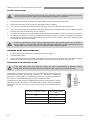
WATER TEMPERATURE
The solar control unit and pump ensure water circulates between the solar collectors and storage cylinder until the
water at the base of the cylinder reaches approximately 65°C. Under these conditions water at the hot outlet may
exceed 85°C. During periods of low solar gain supplementary heating occurs to a minimum of 60°C for electric
boosted systems and 70°C for gas boosted systems.
7RPHHW$XVWUDOLDQUHJXODWRU\UHTXLUHPHQWVVXSSOHPHQWDU\KHDWLQJPXVWEHRSHUDWLRQDO
IMPORTANT
TURNING OFF THE WATER HEATING SYSTEM
If you plan to be away for only a few nights, we suggest you leave the water heating system switched on. If it is
necessary to switch off the water heater, do so as outlined below:
(OHFWULF%RRVWHG6\VWHPV
Switch off the electrical supply to the supplementary heating element. The switch is usually marked and
located in the electricity meter box of the dwelling.
Switch off the electric supply to the solar controller and pump.
*DV%RRVWHGV\VWHPV
Switch off the electric supply to the gas booster.
Switch off the electric supply to the solar controller and pump.
TURNING ON THE WATER HEATING SYSTEM
(OHFWULF%RRVWHGV\VWHP
Switch on the electric supply to the supplementary heating element(s). The switch is usually marked and
located in the electricity meter box of the dwelling.
Switch on the electrical supply to the solar controller pump. Electric and solar water heating will now occur
as required. It may take a number of hours before hot water is available.
*DV%RRVWHGV\VWHPV
Rinnai
Switch on the electrical supply to the gas booster.
Switch on the electrical supply to the solar controller and pump. Solar water heating will now occur. Hot
water is available immediately from the gas booster when hot water tap is opened, irrespective of solar heat
gain.
5
EVT Split System Operation and Installation Manual
WARNINGS AND IMPORTANT INFORMATION
WATER QUALITY
The water quality of most public supplies is suitable for the water heating system. The water quality from bore wells
is generally unsuitable for the water heating system. Refer to separate ‘Warranty Terms and Conditions’ document
for water quality parameters and how they affect the warranty conditions. If in doubt about the water quality, have
it checked against the parameters listed in the warranty conditions. The system is not suitable as a pool or spa
heater.
DRAINING AND FILLING THE WATER HEATING SYSTEM
'UDLQLQJRU¿OOLQJQRUPDOO\RFFXURQO\GXULQJLQVWDOODWLRQRUVHUYLFLQJDQGPXVWEHFDUULHGRXWE\DQDXWKRULVHG
person.
MAINTENANCE AND REGULAR CARE
Operate the easing gear of the PTR as described in the section ‘Safety Devices’ on page 4.
7KHRYHUÀRZWUD\VXSSOLHGE\LQVWDOOHUDQGGUDLQXQGHUQHDWKWKHVWRUDJHF\OLQGHULI¿WWHGVKRXOGEHSHULRGLFDOO\
checked to ensure there are no blockages.
SERVICING AND REPAIR
Our Servicing network personnel are fully trained and equipped to give the best service on your appliance. If your
appliance needs service, ring one of the service contact numbers on the back of this booklet.
It is recommended that the system be serviced at least every 5 years.
The pressure and temperature relief valve and expansion control valve must be checked for performance or
replaced by an authorised person at intervals not exceeding 5 years or more frequently in areas where the water
LVFODVVL¿HGDVVFDOLQJZDWHUUHIHUWRWKHVXSSOLHGZDUUDQW\ERRNOHW
,WLVUHFRPPHQGHGWKDWWKHVDFUL¿FLDODQRGH¿WWHGWR*ODVV/LQHGF\OLQGHUVEHLQVSHFWHGHYHU\\HDUVRUPRUH
frequently in areas where there is a high incidence of water deposits. This does not apply to Stainless Steel
cylinders. Anodes suited to hard and soft water, are available from Rinnai.
If the electric conduit, power supply cord or plug to the water heater is damaged, they must be replaced by an
DXWKRULVHGSHUVRQLQRUGHUWRDYRLGDKD]DUG7KHSRZHUVXSSO\FRUGDQGSOXJLI¿WWHGPXVWEHUHSODFHGE\D
genuine replacement part available from Rinnai.
Rinnai
6
EVT Split System Operation and Installation Manual
SAVE A SERVICE CALL
%HIRUHFRQWDFWLQJ5LQQDLIRUVHUYLFHSOHDVHIROORZWKHIDXOW¿QGLQJJXLGH,IWKHSUREOHPSHUVLVWVRUWKLVLQIRUPDWLRQ
doesn’t answer your questions, contact Rinnai on the phone number on the back of this manual
Service call outs attending to any condition or fault that is not related to Rinnai product or components may be
chargeable.
,168)),&,(172512+27:$7(5
([FHVVLYHKRWZDWHU
consumption
(OHFWULF%RRVWHG6\VWHPV
Often people are surprised at the amount of hot water used, especially when
showering. If the amount of hot water used during the day exceeds the storage capacity
RIWKHF\OLQGHULWLVOLNHO\WKDWWKHUHZLOOEHLQVXI¿FLHQWKRWZDWHU
*DV%RRVWHG6\VWHPV
,QVXI¿FLHQWÀRZPD\RFFXULIPXOWLSOHRXWOHWVDUHLQXVHDWWKHVDPHWLPHDQGH[FHHG
WKHUDWHGÀRZFDSDFLW\RIWKHJDVERRVWHU,IVRUHGXFHWKHQXPEHURIRXWOHWVLQXVH
&RQVLGHUGLVFXVVLQJZLWK\RXULQVWDOOHU¿WWLQJZDWHUVDYLQJ¿[WXUHVDQGRUÀRZFRQWURO
or pressure limiting valves to reduce consumption.
Incorrect solar system size
The system may not have been adequately sized to suit the household.
Temperature and pressure
UHOLHIYDOYHH[SDQVLRQ
FRQWUROYDOYHGLVFKDUJLQJ
ZDWHUFRQWLQXRXVO\
3759DOYHV(&99DOYHVLI¿WWHG
It is normal and desirable that this valve allows a small quantity of water to be
discharged during the heating cycle. If it discharges more than a standard bucket
of water during a 24 hour period or discharges continuously there may be another
problem
If water continuously dribbles from the valve, try easing the valve gear for a few
seconds as described in the section ‘Maintenance and Regular Care’ on page 6.
This may dislodge any foreign matter and alleviate the problem.
,IWKHYDOYHGLVFKDUJHVDWKLJKÀRZVFRQWDFW\RXULQVWDOOHURU5LQQDLWRGLVFXVV
Booster heating not
RSHUDWLQJRULQVXI¿FLHQW
gas supply for gas boosted
heating system
Electric boosted Systems:
Check to ensure the electric isolating switch(es) at the switchboard (usually marked
“Hot water” or “water heater”) is switched ‘ON’.
Check to ensure that the electric fuses for hot water at the switchboard are intact
If running on Off-Peak, discuss boosting times with electricity supplier.
%RRVWHUKHDWLQJQRWRSHUDWLQJRULQVXI¿FLHQWJDVVXSSO\IRUJDVERRVWHGKHDWLQJ
system
*DV%RRVWHG6\VWHPV
Check to ensure the power cord of the gas booster is plugged in and switched ‘on’.
Check gas is available and the isolation valve is opened
Close the hot tap and wait for 10 seconds and open it again. The hot tap must be
RSHQHGHQRXJKWRHQVXUHWKDWWKHÀRZUDWHLVVXI¿FLHQWWROLJKWWKHJDVERRVWHU
Check if there is gas supply to other appliances in the rest of the house
Booster thermostat settings
(OHFWULF%RRVWHG6\VWHPV
Check the temperature of hot water delivered with a thermometer placed under the
closest outlet (usually the kitchen sink) on a non-tempered hot water line
This test should be done early in the morning after overnight electrical boosting
before any hot water is used. The temperature of the water delivered should be at
least 55°C (allowing for heat losses in pipe work)
If this is not the case or the temperature may need to be increased. Contact your
installer or Rinnai to discuss adjusting the thermostat.
12:$7(5)5207+(+277$3
5HVWULFWLRQLQWKHKRWWDS
RUIDLOXUHRIWKHFROGZDWHU
supply to the heater
Rinnai
&KHFNIRUZDWHUÀRZDWWKHRWKHUKRWWDSVDQGWKDWWKHFROGZDWHULVRODWLRQYDOYHLVIXOO\
open
7
EVT Split System Operation and Installation Manual
SAVE A SERVICE CALL
+,*+(/(&75,&,7<25*$6%,//
+RWZDWHUXVDJHSDWWHUQV
(OHFWULF%RRVWHG6\VWHPV
If using an off peak (overnight) boosted electrical system, the time of use of the water
may affect whether heating is done by electric element or solar energy. This is because
both solar heated water and electrically heated water are stored in the same cylinder.
(This is not a problem with gas boosted systems, and is less of an issue with mid
element storage cylinders).
If the bulk of hot water is used in the morning, there will be cold water in the cylinder for
the sun to heat during the day leading to lower electricity usage.
If the bulk of the hot water is used in the evening, the electric element will reheat the
water overnight. In the morning there will be no cold water in the storage cylinder for the
sun to heat.
Consider changing your usage pattern to optimise solar energy usage.
High electricity cost
(OHFWULF%RRVWHG6\VWHPV
The electricity tariff will determine the running costs of the system. Contact the
HOHFWULFLW\VXSSOLHUWRFRQ¿UPZKDWWKHVHWDULIIVDUH
6RODUFRQWUROXQLWVZLWFKHG
off
If the solar control unit is switched off there will be no solar pre- heating of water
resulting in the water being heated entirely by electricity or gas’ boosting’
Check the power outlet for the solar control unit is switched on
Temperature and pressure
UHOLHIYDOYHH[SDQVLRQ
FRQWUROYDOYHGLVFKDUJLQJ
ZDWHUFRQWLQXRXVO\
6HHHQWU\XQGHUµ,QVXI¿FLHQWRU1R+RW:DWHU¶
/DFNRIVRODUJDLQ
Reduced sunlight due to overcast weather in summer or low solar contribution in
winter will result in an increased dependence on electricity or gas boosting. Higher
electricity or gas bills under these conditions, especially in winter, are normal.
If the solar collectors are shaded by trees or other objects, or the glass is dirty, the
effectiveness of the collectors is greatly reduced. Arrange for trimming of the trees or
relocation of the solar collectors if the obstruction is permanent. Arrange for cleaning
of the collector glass
Solar collectors incorrectly positioned will also severely affect the solar gain. Check
that positioning and alignment of solar collectors is in accordance with the section
‘System Orientation and Inclination’ on page 21.
%52.(125'$0$*('(9$&8$7('78%(6
%URNHQ(YDFXDWHG7XEHV
If any of the evacuated tubes have a clear or white bottom this may indicate that the
vacuum within the tube has gone and the tube will not be performing properly. The
tubes are normally a silver colour.
If the vacuum in the tube is gone or the tube is obviously broken, the system can
still be used. The remaining tubes will still be fully operational. However the system
performance will be reduced.
If a tube is broken or damaged it should be replaced. Contact Rinnai to discuss.
12,6<62/$5&2//(&7256
Noise from solar collectors
Occasionally on days of high solar gain, the water temperature in the collector may
become very high. The noise may be similar to a boiling kettle, or an expanding
contracting metallic sound. The collector is designed to withstand these conditions, and
no action is needed, unless it is extreme. Contact Rinnai to discuss if you have any
concerns.
62/$53803&217,18286/<23(5$7,1*
Temperature sensor leads
not in place
The system will not operate correctly if the temperature sensor leads are not correctly
positioned (dry well on storage cylinder and in the evacuated tube header). Contact
your installer or Rinnai to discuss.
:$7(5+$00(5
+RWDQGFROGZDWHU
plumbing in the premises
Rinnai
Contact your installer or a plumber to discuss checking the clipping of hot and cold
water pipe work and install a pressure limiting valve or water hammer arrestor as
required
8
EVT Split System Operation and Installation Manual
SPECIFICATIONS
GENERAL
6SOLWVRODUKRWZDWHUV\VWHPVDUHVSHFL¿HGDFFRUGLQJWRWKHJUDGHRIVWRUDJHF\OLQGHUPDWHULDOF\OLQGHUFDSDFLW\
number of solar collectors and boost type and capacity. Boost capacity for gas boosted system depends on the gas
booster model selected. Boost capacity for electrically boosted systems depends on the power rating of electric
KHDWLQJHOHPHQWVDQGZKHWKHURQHRUWZRHOHFWULFKHDWLQJHOHPHQWVDUH¿WWHG
SYSTEM
6SHFL¿FDWLRQVIRUWKHYDULRXVFRPSRQHQWVDUHVKRZQEHORZ
*ODVV/LQHG
&\OLQGHUV
*ODVV/LQHG
&\OLQGHUV
6WDLQOHVV6WHHO
&\OLQGHUV
6RODUÀRZDQGUHWXUQFRQQHFWLRQ
Rp ½
Rp ½
Rp ½
PTR valve connection:
Rp ½
Rp ½
Rp ¾
Cold inlet connection:
Rp ¾
Rp ¾
Rp ¾
Hot outlet connection:
Rp ¾
Rp ¾
Rp ¾
1000 kPa
850 kPa
850 kPa
6\VWHP7\SH
PTR valve setting
Rating of PTR Valve supplied
10 kW
10 kW
10 kW
Expansion Control Valve (ECV) setting
850 kPa
700 kPa
700 kPa
Max supply pressure with ECV
680 kPa
550 kPa
550 kPa
Max supply pressure without ECV
800 kPa
680 kPa
700 kPa
Pressure limiting valve rating
(supplied by installer if required)
500 kPa
500 kPa
500 kPa
Flow Control Valve
$ÀRZFRQWUROYDOYHLV¿WWHGWRWKHSXPSDQGFRQWUROOHUDVVHPEO\
,W¶VSXUSRVHLVWRDOORZWKHZDWHUÀRZUDWHWKURXJKWKHFROOHFWRUVDQGVWRUDJHF\OLQGHUWREHFRQWUROOHGWRRSWLPLVHWKHSHUIRUPDQFH
of the system.
Differential Temperature Controller
The primary task of the differential temperature controller is to control the operation of the pump to optimize solar energy
collection. This task is performed by measuring the temperature differential between the hot sensor and the cold sensor. When
the differential exceeds 9°C the pump is activated and water passes through the collectors collecting solar energy. When the
differential falls below 5°C the pump turns off.
A secondary task of the controller is to stop energy collection when the cylinder is full of hot water. This is referred to as no
load protection and the pump is shut down if the temperature of the water going to the collectors exceeds 65°C. At such a
temperature in the base of the cylinder, the temperature of water in the top of the cylinder is expected to be about 85°C.
When the controller is in low temperature mode it will also circulate water through the evacuated tube header when the roof
temperature becomes cold. This is to prevent damage to the system due to freezing. See 19 for more details.
Rinnai
9
EVT Split System Operation and Installation Manual
SPECIFICATIONS
EVACUATED TUBE SOLAR COLLECTORS
Number of tubes
Waterways
Threaded Connections
Maximum operating temperature
Frame material
Overall dimensions
Weight empty
Potential solar output at PTR relief conditions
(97$
(97$
(97$
20
25
30
Copper
Copper
Copper
R¾
R¾
R¾
850 kPa
850 kPa
850 kPa
Aluminium
Aluminium
Aluminium
1980 x 1692 x 145
1980 x 2082 x 145
1980 x 2472 x 145
80 kg
100 kg
120 kg
1.30 kW
1.63 kW
1.96 kW
Frost Protection to -12 °C.
Frost Protection
Power must be on at the pump, and the solar controller must be in
low temperature mode. See page 19
For more information on frost protection, refer to the warranty booklet.
Rinnai
10
EVT Split System Operation and Installation Manual
SPECIFICATIONS
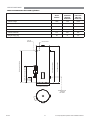
STORAGE CYLINDERS
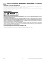
*ODVV/LQHG*DV%RRVWHG&\OLQGHUV
6*
(6*
6*
(6*
6*6/
(6*6/
6*6/
(6*6/
Cylinder height
1530
1825
1475
1695
PTR / solar return
1310
1605
1215
1430
Flow line to collectors
665
665
540
540
Cold water inlet
225
225
90
90
Gas supply and hot water out
940
1235
885
1105
*DVERRVWHUÀXHRXWOHW
1400
1695
1345
1565
Cylinder diameter
515
515
625
625
Weight empty
66 kg
88 kg
91 kg
107 kg
System Depth
710
710
820
820
GAS BOOSTER FLUE OUTLET
GAS SUPPLY AND
HOT WATER OUTLET
P&TR VALVE
COLD
WATER
INLET
FLOW LINE TO COLLECTORS
P&TR / SOLAR RETURN
CYLINDER HEIGHT
SOLAR
RETURN
CYLINDER DIAMETER
SYSTEM DEPTH
TEMPERATURE SENSOR
DRY WELL
Rinnai
11
EVT Split System Operation and Installation Manual
SPECIFICATIONS
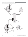
*ODVV/LQHG(OHFWULF%RRVWHG&\OLQGHUV
6(
(6(
6(6/
(6(6/
606/
(606/
6(6/
(6(6/
606/
(606/
Cylinder height
1825
1475
1695
PTR / solar return / hot water outlet
1605
1215
1430
Flow line to collectors
665
540
540
Cold water inlet
225
90
90
Cylinder diameter
515
625
625
Weight empty (kg)
88
91
107
CYLINDER HEIGHT
HOT WATER OUTLET
P&TR VALVE
COLD
WATER
INLET
FLOW LINE TO COLLECTORS
PTR / SOLAR RETURN
SOLAR
RETURN
CYLINDER DIAMETER
TEMPERATURE
SENSOR
DRY WELL
Rinnai
12
EVT Split System Operation and Installation Manual
SPECIFICATIONS
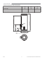
6WDLQOHVV6WHHO*DV%RRVWHG&\OLQGHUV
Cylinder height
1700
2090
PTR / solar return / hot water outlet
1490
1880
Gas supply and hot water outlet
880
1270
*DVERRVWHUÀXHRXWOHW
1345
1735
56
68
P&TR VALVE
CYLINDER HEIGHT
Weight empty (kg)
SOLAR
RETURN
650
300
GAS BOOSTER FLUE OUTLET
GAS SUPPY AND
HOT WATER OUTLET
210
600
COLD WATER
INLET
795
Rinnai
13
EVT Split System Operation and Installation Manual
SPECIFICATIONS
6WDLQOHVV6WHHO(OHFWULF%RRVWHG&\OLQGHUV
Cylinder height
995
1700
2090
PTR / solar return / hot water outlet
1205
1490
1880
46
56
68
P&TR VALVE & HOT WATER OUTLET
Weight empty (kg)
SOLAR
RETURN
CYLINDER HEIGHT
650
300
210
600
COLD
WATER
INLET
Rinnai
14
EVT Split System Operation and Installation Manual
SPECIFICATIONS
GAS BOOSTERS
0RGHO1DPH
6
6
6L
6
Boost capacity at 20°C rise (l/min)
20
26
26
37
Boost capacity at 25°C rise (l/min)
16
24
24
32
0D[LPXPUDWHGÀRZOPLQ
20
26
26
37
Minimum water supply pressure for maximum rated
ÀRZN3D1
120
200
200
180
Frost protection
Yes
Gas consumption maximum (MJ/h)
125
188
188
250
Gas consumption minimum (MJ/h)
18
23
14
21
Hot water delivery temperature (°C) 70
Dimensions - height x width x depth (mm)
Weight (kg)
530 x 350 x 194
15
21
600 x 470 x 244
15
29
8QLWVZLOORSHUDWHDWORZHUSUHVVXUHVEXWWKHUDWHGÀRZZLOOQRWEHDFKLHYHG
2
Gas boosters for Solar hot water applications must be set by Rinnai to deliver a minimum temperature of 70°C. Solar Gas
boosters will be marked as Solar. Units not marked ‘Solar’ MUST NOT be used.
*
These models are made to order.
Rinnai
15
EVT Split System Operation and Installation Manual
INSTALLATION - ALL SYSTEMS
REGULATIONS AND OCCUPATION HEALTH AND SAFETY (OH&S)
Installation and commissioning must be performed by authorised persons.
WARNING
Solar systems must be installed in accordance with these instructions and all regulatory requirements
which exist in your area including those in relation to manual lifting, working at heights and on roofs.
Applicable publications and regulations may include:
AS/NZS 5601 Gas Installations
AS/NZS 3500 National Plumbing and Drainage
AS/NZS 3000 Wiring rules
Building Codes of Australia (BCA)
Local Occupational Health and Safety (OH&S) regulations
This appliance is not suitable for use as a domestic spa pool or swimming pool heater.
Solar collectors are heavy and bulky items and are usually positioned on the roofs of buildings.
Australian State and Territories have a principal Occupational Health and Safety (OH&S) Act which
contains requirements relating to the handling of large, bulky or awkward items and the prevention of
falls from elevated surfaces. Persons installing solar collectors must be aware of their responsibilities
DQGEHDGHTXDWHO\WUDLQHGDQGTXDOL¿HGLQDFFRUGDQFHZLWKORFDO2+6UHTXLUHPHQWV
LOCATION - GENERAL INFORMATION
All system components must be in an accessible location. The storage cylinder must be accessible without the use
RIDODGGHURUVFDIIROG6XI¿FLHQWFOHDUDQFHVVKDOODOORZDFFHVVWRDQGUHPRYDORIDOOVHUYLFHDEOHSDUWV(QVXUHWKH
375YDOYHSXPSNLWGUDLQOLQHVDQGWKHUPRVWDWDQGHOHPHQWVIRUHOHFWULFV\VWHPVKDYHVXI¿FLHQWFOHDUDQFHVDQG
are accessible for service and removal. The information on any data plates must also be readable. In the case of
vitreous enamel lined cylinders, leave a clearance of the height of one storage cylinder above the cylinder being
LQVWDOOHGVRWKHVDFUL¿FLDODQRGHFDQEHLQVSHFWHGDQGUHSODFHG7KLVGRHVQRWDSSO\WRVWDLQOHVVVWHHOF\OLQGHUV
Select suitable areas of roof on which to install the solar collectors as close as practicable to the cylinder. Ensure
that the area is even and without cracked or damaged tiles. Collectors should be positioned for optimum solar
EHQH¿W5HIHUWRWKHVHFWLRQµ,QVWDOODWLRQ(YDFXDWHG7XEHV¶RQSDJHIRUPRUHLQIRUPDWLRQ
The solar pump kit and gas booster heater require an AC 240V power supply. A weatherproof 240V, 10A earthed
power point must therefore be provided adjacent to these.
All electrically boosted solar hot water heating elements must be connected to an independent, fused, AC 240V 50
Hz power supply with an isolating switch installed at the switch board.
STORAGE CYLINDER LOCATION
The storage cylinder should be placed as close as practicable to the most frequently used hot water outlet point or
points to minimise the delay time for hot water delivery. This will usually be the kitchen tap.
The solar storage cylinders have an ingress protection rating of IPX4 making them suitable for internal or external
installation. Rinnai ‘external’ gas boosters are suitable for external installation only.
Storage cylinders must be installed in freestanding mode on a level and stable base. For external installations,
storage cylinders should be mounted on a concrete base at least 50mm thick or on well seasoned, evenly spread
hardwood slats with a thickness of at least 25mm. Where property damage can occur, storage cylinders should be
LQVWDOOHGZLWKDQDSSURYHGVDIHWUD\RYHUÀRZWUD\
Ensure the cylinder does not stand on wet surfaces.
Rinnai
16
EVT Split System Operation and Installation Manual
INSTALLATION - ALL SYSTEMS
GAS BOOSTER LOCATION
The gas booster is designed for ‘Outdoor’ Installation only. As such, it must be located in an above ground open
air situation with natural ventilation, without stagnant areas, where gas leakage and products of combustion are
rapidly dispersed by wind and natural convection.
WATER PIPES
All hot water pipework should be insulated with sealed Polyethylene foamed or equivalent insulation to optimise
SHUIRUPDQFH DQG HQHUJ\ HI¿FLHQF\ 6XFK LQVXODWLRQ PD\ DOVR EH PDQGDWRU\ XQGHU ORFDO UHJXODWLRQV 5LQQDL
UHFRPPHQGLQVXODWLRQWRDFKLHYHDQ5YDOXHRI.P::LWKWKHH[FHSWLRQRIVRODUFROOHFWRUÀRZDQGUHWXUQ
pipes, water pipe sizing should be performed in accordance with AS/NZS 3500. All external pipework MUST be
insulated to prevent frost damage.
7KHFROOHFWRUÀRZDQGUHWXUQSLSHVVKRXOGEHDPLQLPXPRIPPFRSSHUWXEH3ODVWLFSLSHPXVWQRWEHXVHG
3ODVWLFSLSHLVQRWVXLWHGWRWKHKLJKZDWHUWHPSHUDWXUHVDQGSUHVVXUHVWKDWPD\RFFXULQWKHFROOHFWRUÀRZDQG
return system.
WARNING
7KHFROOHFWRUÀRZDQGUHWXUQSLSHVVKRXOGEHDPLQLPXPRIPPFRSSHUWXEH3ODVWLFSLSHPXVWQRW
be used. Plastic pipe is not suited to the high water temperatures and pressures that may occur in the
FROOHFWRUÀRZDQGUHWXUQV\VWHP
7KHPD[LPXPUHFRPPHQGHGFRPELQHGOHQJWKVRIWKHVRODUÀRZDQGUHWXUQSLSHVDUHDVIROORZV
EVT20A and EVT25A
EVT30A and 2 x EVT20A
Copper Pipe DN 15 (1/2”)
60 m
50 m
Copper Pipe DN20 (3/4”)
not recommended
60 m
WATER SUPPLY
The maximum water pressures for the various systems are listed on page 9. Approved pressure limiting valves
may be required if the ‘Maximum’ rated water supply pressures are exceeded. For gas boosted systems to achieve
WKHUDWHGÀRZWKURXJKWKHRXWOHWRIWKHFRQWLQXRXVÀRZZDWHUKHDWHUWKHPLQLPXPZDWHUVXSSO\SUHVVXUHVPXVWEH
VXSSOLHG7KHV\VWHPVZLOORSHUDWHDWORZHUSUHVVXUHVEXWWKHUDWHGÀRZZLOOQRWEHDFKLHYHG
Water chemistry and impurity limits are detailed in the separate Warranty document. Most metropolitan water
supplies fall within these requirements. If you are unsure about water quality, contact your water authority. If sludge
RUIRUHLJQPDWWHULVSUHVHQWLQWKHZDWHUVXSSO\DVXLWDEOH¿OWHUVKRXOGEHLQFRUSRUDWHGLQWKHZDWHUVXSSO\WRWKH
storage cylinder.
Rinnai
17
EVT Split System Operation and Installation Manual
INSTALLATION - ALL SYSTEMS
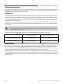
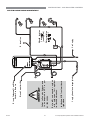
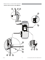
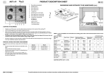
HOT WATER DELIVERY TEMPERATURE
Local regulations and/or the requirements of AS/NZS 3500.4 must be considered regarding the temperature
limitations of hot water supplied to areas used primarily for personal hygiene. The temperature of water to these
areas is limited to 45°C for early childhood centres, primary and secondary schools and nursing homes or similar
facilities for young, aged, sick or people with disabilities and 50°C for all other buildings. To comply with these
requirements, a temperature limiting device, such as a thermostatic mixing or tempering valve, will be required on
all solar hot water systems as detailed below.
rc
Sola
olle
ct or
s
Gas boost
Kitchen
Hot water outlet
Cold Inlet
Gas supply
Solar cold water inlet
Solar hot water return
Storage
cylinder
Heated water from storage cylinder
Rinnai gas continuous flow water heater for
solar applications, preset to deliver hot water
at a fixed temperature of 70°C or higher
Cold water supply
Laundry
Ensuite
Bathroom
TLD
Note: TLD = Temperature Limiting Device
7HPSHUHG*DV+RW:DWHU6\VWHP
Heated water from storage cylinder
Electrically
boosted
storage
cylinder
Solar hot water return
Solar cold water inlet
s
ctor
olle
rc
Sola
Kitchen
Laundry
Ensuite
Bathroom
TLD
Note: TLD = Temperature Limiting Device
Cold water supply
7HPSHUHG(OHFWULF+RW:DWHU6\VWHP
Rinnai
18
EVT Split System Operation and Installation Manual
INSTALLATION - ALL SYSTEMS
FROST PROTECTION MODE
The Solar Controller has two different temperature modes. Low temperature mode and standard operating mode.
When the controller is in low temperature mode, the pump will circulate water to the collectors when the temperature
on the roof drops low enough, to prevent freezing of the collectors.
For systems installed with evacuated tube collectors, the controller MUST be set to low temperature mode for the
warranty on the collector to be valid. Refer warranty booklet for more details.
The factory default is Low Temperature Mode.
)URVWSURWHFWLRQGLSVZLWFKHVRQVRODUFRQWUROOHU
Mode
Dip Switch K1
Dip Switch K2
Standard operating mode
SOM ‘ON
CIR
Low temperature mode
LTM
CIR
Power MUST be turned OFF to the Controller before opening the controller box.
WARNING
Rinnai
Power MUST be OFF when adjusting Dip Switches
19
EVT Split System Operation and Installation Manual
INSTALLATION - ALL SYSTEMS
VALVES AND FITTINGS
7KHIROORZLQJYDOYHVDQG¿WWLQJVDUHVXSSOLHGZLWK\RXUVRODUKRWZDWHUV\VWHP
A combined pressure and temperature (PTR) relief valve, capacity 10 kW. Relief valve pressure settings
YDU\ZLWKPRGHOV7KLVYDOYHLV¿WWHGDWWKHWRSRIWKHVWRUDJHF\OLQGHU7KH375YDOYHLVDVDIHW\GHYLFHDQG
LWLVPDQGDWRU\WKDWLWLV¿WWHGE\WKHLQVWDOOHULQDOOLQVWDOODWLRQV
$ QRQ UHWXUQ YDOYH ¿WWHG RQ WKH VRODU SXPS RXWOHW WR SUHYHQW EDFNÀRZ WKURXJK WKH SXPS IURP WKH VRODU
collectors. This valve is factory connected.
)RUJDVERRVWHGV\VWHPVHOERZFRQQHFWLRQVIRUWKHKRWFROGDQGJDVVXSSO\DUH¿WWHGDWWKHERWWRPRIWKH
gas booster.
Fittings as shown on pages 36 to 41 or 48 to 51.
7KHIROORZLQJYDOYHV¿WWLQJVDUHWREHVXSSOLHGE\WKHLQVWDOOHU
Rinnai
$FROGZDWHUH[SDQVLRQFRQWUROYDOYH(&9$Q(&9PXVWEH¿WWHGLQ:HVWHUQ$XVWUDOLDDQG6RXWK$XVWUDOLD
to the cold water supply to the storage cylinder to comply with local regulations. An ECV is recommended
in all other geographical areas where the water supply has a tendency to cause scaling. This will reduce hot
water discharge from the pressure and temperature relief (PTR) valve which minimises wear on this valve.
A stop cock, non return valve and line strainer. Combination valves incorporating two or more of these
IXQFWLRQVVXFKDVµ7ULR¶YDOYHVDUHVXLWDEOH7KHVHDUH¿WWHGWRWKHFROGZDWHUVXSSO\WRWKHVWRUDJHF\OLQGHU
by the installer.
Cold water supply and hot water discharge pipework to and from the storage cylinder.
6RODUFROOHFWRUÀRZDQGUHWXUQSLSHVDQGVWRUDJHF\OLQGHUFRQQHFWLRQV
An isolating valve and connection union for the gas supply to the gas booster.
An approved pressure limiting valve (supplied with some systems) is required if the maximum rated water
supply pressure on page 9 is exceeded.
20
EVT Split System Operation and Installation Manual
INSTALLATION - EVACUATED TUBES
REGULATIONS AND OCCUPATION HEALTH AND SAFETY (OH&S)
Installation and commissioning must be performed by authorised persons. Rinnai solar systems must be installed
in accordance with these Instructions and all regulatory requirements which exist in your area including those in
relation to manual lifting, working at heights and on roofs. Applicable publications and regulations may include:
AS/NZS 5601 Gas Installations
AS/NZS 3500 National Plumbing and Drainage
AS/NZS 3000 Wiring rules
Building Codes of Australia
Local Occupational Health and Safety (OH&S) regulations
WARNING
Solar collectors are heavy and bulky items and are usually positioned on the roofs of buildings. Each
Australian State and Territory has a principal Occupational Health and Safety (OH&S) Act which contains
requirements relating to the handling of large, bulky or awkward items and the prevention of falls from
elevated surfaces. Persons installing solar collectors must be aware of their responsibilities and be
DGHTXDWHO\WUDLQHGDQGTXDOL¿HGLQDFFRUGDQFHZLWKORFDO2+6UHTXLUHPHQWV
SYSTEM ORIENTATION AND INCLINATION
The performance of any solar hot water system is determined by the way that the system is installed. In Australia,
the solar collectors ideally should face the equator (North) as shown below. Where this orientation is not practical,
collectors facing within 45 degrees from North (between North-East and North-West) are acceptable and will only
UHGXFHHI¿FLHQF\E\DSSUR[LPDWHO\
The inclination of the solar collectors should ideally be the same as the latitude angle of the site. Inclinations within
GHJUHHV RI WKH ODWLWXGH DQJOH RI WKH VLWH ZLOO RQO\ UHGXFH HI¿FLHQF\ E\ DSSUR[LPDWHO\ 0RVW URRIV ZLWKLQ
Australia have a slope of between 20° and 25° and provide an appropriately angled mounting surface.
Orientation and inclination of collectors
,QVWDOOHUVPXVWHQVXUHWKH\FRPSO\ZLWKUHOHYDQWORFDOUHJXODWLRQVLQUHJDUGVWRLQFOLQDWLRQDQGRULHQWDWLRQ
,QVRPHLQVWDQFHVDGGLQJH[WUDFROOHFWRUVPD\DOORZPRUHÀH[LELOLW\LQRULHQWDWLRQ
&LW\
/DWLWXGH
&LW\
/DWLWXGH
&LW\
/DWLWXGH
Adelaide
35°S
Canberra
35°S
Melbourne
38°S
Albany
35°S
Darwin
12°S
Perth
32°S
Alice Springs
20°S
24°S
Dubbo
32°S
Port Hedland
Brisbane
27°S
Geraldton
28°S
Rockhampton
24°S
Broken Hill
31°S
Hobart
42°S
Sydney
34°S
Cairns
17°S
Mildura
Townsville
19°S
Rinnai
34°S
Latitudes of Australian Cities
21
EVT Split System Operation and Installation Manual
INSTALLATION - EVACUATED TUBES
SOLAR COLLECTOR ROOF MOUNTING OPTIONS
Rinnai evacuated tube solar collectors may be installed on the following roof types:
Pitched tile roof
Flat roof
Pitched metal roof
Roof construction must be checked to ensure that the roof timbers are capable of supporting the additional load.
(Refer to AS/NZS 3500.4 Appendix G).
5LQQDL(YDFXDWHGWXEHV\VWHPVDUH127FHUWL¿HGIRULQVWDOODWLRQLQF\FORQHDUHDV
WARNING
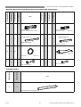
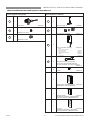
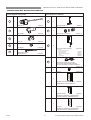
COMPONENTS
(YDFXDWHG7XEH&ROOHFWRU&RPSRQHQWV
Each evacuated tube collector installation requires several components packaged within different boxes. Please
ensure you have all the relevant boxes before starting installation
TILED PITCH ROOF
20
EVTMAN20R5A
Manifold, base frame and “Tail
Stock”
Pitch Roof Mounting Kit
25
30
1
EVTMAN25R5A
40
20
2
1
1
EVTMAN30R5A
25
40
1
1
EVTFRM20R5A
1
2
EVTPIT20R5A
1
2
EVTPIT25R5A
30
2
1
1
2
1
2
1
EVTPIT30R5A
1
EVTFRF20R5A
Flat Roof Frames
FLAT ROOF
EVTFRF25R5A
1
EVTFRF30R5A
1
EVTUBE10R5A
2
1
4
2
1
4
Evacuated Tubes
EVTUBE15R5A
Additional Installation
Components
Rinnai
1
2
EVTRFBRKT
1
1
1
1
IKEVTR5A
1
1
1
1
22
1
1
2
1
1
1
EVT Split System Operation and Installation Manual
INSTALLATION - EVACUATED TUBES
-
(97)505$
(97)505$
1
(970$15$
(970$15$
1
(970$15$
(970$15$
1
Item
(970$15$
(970$15$
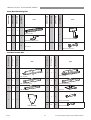
0DQLIROG%DVH)UDPHDQG%RWWRP6XSSRUW$VVHPEO\.LW&RPSRQHQWV
1
1
1
-
Manifold Header
(to suit required number of tubes)
Bottom Support Assembly
(Single Tube Cap
40011214)
EVT20A 1560 mm
EVT25A 1950 mm
EVT30A 2340 mm
1980 mm long
-
2
2
2
-
2
2
2
%DVH)UDPH5DLO$Base Frame Rail B
20
25
30
-
1
1
1
Heat Transfer Paste
Dust Caps
6
6
6
40011212
40011210
-
9
9
9
M6-12 Nut and Bolt
M8-16 Nut and Bolt
(978%(5$
(978%(5$
(YDFXDWHG7XEHV
10
15
Item
Evacuated Tube (including heat pipe)
Rinnai
23
EVT Split System Operation and Installation Manual
INSTALLATION - EVACUATED TUBES
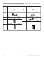
Pitch Roof Rail
-
-
-
(975)%5.7
(975)%5.7
2
(973,75$
(973,75$
2
(973,75$
(973,75$
2
Item
(973,75$
(973,75$
3LWFK5RRI0RXQWLQJ.LWV
-
-
-
4
4
Item
Tiled Roof Mounting Hook
Tiled Roof Mounting Clips
-
-
-
20
-
-
-
8
M6 Screws
M8-16 Nut and Bolt
1
EVTFRF30R5A
EVTFRF30R5A
1
EVTFRF25R5A
EVTFRF25R5A
1
Item
EVTFRF20R5A
EVTFRF20R5A
)ODW5RRI)UDPH.LWV
2
2
2
FRF Leg Side
FRF Leg Mid
3
3
3
3
3
3
FRF Side Brace Short
4
4
FRF Side Brace Long
4
6
6
6
FRF Foot
FRF Back Brace
2
3
3
2
2
3
M6-25 Nut and Bolt
39
FRF Bracket
Rinnai
Item
39
39
M6-12 Nut and Bolt
24
EVT Split System Operation and Installation Manual
INSTALLATION - EVACUATED TUBES
,.(975$
,.(975$
2WKHU,QVWDOODWLRQ.LWV
Item
1
2
1
Item
Elbow
21201071
Air Bleed Valve
11007701
Air Bleed Valve Adaptor
16601100
Hot Sensor Lead
31002706
Instruction Manual
15401100
1
1
Warranty Booklet
15401041
1
1
STC form
Rinnai
15401023
25
EVT Split System Operation and Installation Manual
INSTALLATION - EVACUATED TUBES
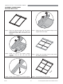
ASSEMBLY INSTRUCTIONS
$VVHPEOH%DVH)UDPH
Step 1. Place the manifold header and the bottom
support assembly upside down. Place the
three Base Frame Rail A as shown in the
diagram.
Step 2. Fasten the rails to the header using the nuts
supplied with the header.
Step 3. Fasten the rails to the bottom support
assembly using the M8 nuts and bolts
supplied.
Step 4. Position the two Base Frame B rails under
the existing components
Step 5. Fasten using the M6 nuts and bolts supplied.
Step 6. Turn assembly up correct way
Rinnai
26
EVT Split System Operation and Installation Manual
INSTALLATION - EVACUATED TUBES
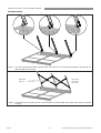
,QVWDOODWLRQRQD3LWFKHG7LOH5RRI
Step 1. Carefully remove a roof
tile.
Step 2. Position the mounting
bracket as shown.
Step 3. Fasten the bracket to roof
structure using suitable
screws.
Step 4. Fasten the bracket to roof
structure.
Step 5. Replace the roof tile.
Step 6. Fit the mounting rail in
bracket and fasten
Step 7. Repeat steps 1 to 6 for
the remaining brackets
and rail.
Step 8. Position the base frame
on the rails.
Step 9. Fasten the assembly
using the mounting clips
Rinnai
27
EVT Split System Operation and Installation Manual
INSTALLATION - EVACUATED TUBES
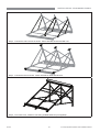
Flat Roof Frame
Step 1. Turn the complete base frame upside down and connect the rear legs and brackets using the M6-12
bolts and M6 nuts as shown.
M6-25 Bolt
& M6 nut
back braces
flex around
each other
Step 2. Connect the back braces as shown. Attach with M6-12 bolts and M6 nuts except where shown otherwise
in image.
Rinnai
28
EVT Split System Operation and Installation Manual
INSTALLATION - EVACUATED TUBES
Step 3. Connect the side braces as shown. Attach with M6-12 bolts and M6 nuts.
Step 4. Connect the feet as shown. Attach with M6-12 bolts and M6 nuts.
Step 5. Turn frame over. Fasten to roof using suitable fasteners (not supplied).
Rinnai
29
EVT Split System Operation and Installation Manual
INSTALLATION - EVACUATED TUBES
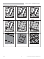
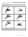
)LWWLQJWKH(YDFXDWHG7XEHV
7KH¿QDQGEXOERQWKHHYDFXDWHGWXEHZLOOEHFRPHKRWZKHQH[SRVHGWRVXQVKLQH7DNHFDUHZKHQ
handling to prevent burns.
WARNING
Step 1. Unscrew the tube cap as shown
Step 2. Slide the evacuated tube through the tube
cap.
Step 3.
Position the dust cap into the header
Step 4. Apply heat transfer paste to heat pipe bulb.
Step 5.
Slide the tube into the header. Soapy water
around the outside of the glass will make
this easier
Step 6. Replace the tube cap.
Step 7.
Repeat steps 1 to 6 for the remaining tubes
Rinnai
30
EVT Split System Operation and Installation Manual
INSTALLATION - EVACUATED TUBES
&RQQHFWLQJSOXPELQJFRQQHFWLRQVDQG7HPSHUDWXUH6HQVRU
Flo
w
Flo
w
Dir
ec t
ion
Step 1. &RQQHFW¿WWLQJVWRFROGZDWHUVLGHRIKHDGHU
&RSSHUÀRZDQGUHWXUQSLSHZRUNLVVXSSOLHG
by installer.
Flow
Direc
tio
Dir
ec t
ion
Step 2. &RQQHFW ¿WWLQJV WR KRW ZDWHU VLGH RI KHDGHU
&RSSHUÀRZDQGUHWXUQSLSHZRUNLVVXSSOLHG
by installer.
n
Step 4. Secure the lead to the header using
silicone to ensure it will not come loose.
Connect the plug end to the solar controller
as described on page 43 and page 53.
Step 3. Connect
temperature
sensor
lead
into header at the KRW ZDWHU HQG.
Ensure that the lead is pushed all the way
into the pocket.
Step 5. ,QVXODWH DOO H[SRVHG ¿WWLQJV DQG SLSHZRUN DV GHVFULEHG LQ WKH VHFWLRQ µ:DWHU 3LSHV¶ RQ SDJH Joining Two Collectors
Two EVT20A collectors can be joined together for a 40 tube system, An Rp 3/4 x Rp 3/4 barrel union is the
suggested connection method. Ensure Connection is well insulated.
Rinnai
31
EVT Split System Operation and Installation Manual
INSTALLATION - GAS BOOSTED SYSTEMS
OVERVIEW OF SYSTEM COMPONENTS
The range of gas boosted solar hot water systems include all the components shown on pages 36 to 40 (refer
to the appropriate diagram depending on cylinder type/size).
7KHSXPSNLWDQGDVVRFLDWHGSOXPELQJFRQQHFWLRQVDUHIDFWRU\SUHDVVHPEOHG$OORWKHUFRPSRQHQWVDQG¿WWLQJV
will require connection on site. The gas booster and pump/controller kit may be mounted to the front of the storage
cylinder casing or in an alternative external location. In all cases the heated outlet of the cylinder is connected to
the cold water inlet of the gas booster.
GAS BOOSTER LOCATION
The gas booster is designed for ‘Outdoor” Installation only. As such, it must be located in an above ground open
air situation with natural ventilation, without stagnant areas, where gas leakage and products of combustion are
UDSLGO\GLVSHUVHGE\ZLQGDQGQDWXUDOFRQYHFWLRQ7KHORFDWLRQPXVWFRPSO\ZLWKWKHFOHDUDQFHVVSHFL¿HGLQ$6
NZS 5601.
The gas booster must be mounted on a vertical structure with the water and gas connections on the underside
pointing downwards. In most installations the gas booster is mounted directly on the storage cylinder using two
custom made mounting brackets (supplied). In all cases the heated outlet of the cylinder is connected to cold water
inlet of the gas booster.
GAS SUPPLY
The maximum gas consumption of the gas booster and the required gas pressure are shown on the appliance data
SODWH,IWKHJDVSLSHVL]LQJLVLQVXI¿FLHQWWKHFXVWRPHUZLOOQRWJHWWKHIXOOSHUIRUPDQFHEHQH¿W*DVSLSHVL]LQJ
must consider the gas input to the gas booster as well as all the other gas appliances on the premises. The gas
PHWHUDQGUHJXODWRUPXVWEHVSHFL¿HGIRUWKLVJDVUDWH$QDSSURYHGVL]LQJFKDUWVXFKDVWKHRQHLQ$61=6
VKRXOGEHXVHG$QDSSURYHGIXOOÀRZLVRODWLRQYDOYHDQGGLVFRQQHFWLRQXQLRQPXVWEH¿WWHGWRWKHJDVVXSSO\LQOHW
RIWKHJDVERRVWHU,VRODWLRQYDOYHVPXVWQRWEH¿WWHGGLUHFWO\WRWKHERRVWHU
HOT WATER DELIVERY TEMPERATURE
*DVERRVWHUVIRUXVHLQVRODUKRWZDWHUV\VWHPVDUHSUHVHWWRGHOLYHUD¿[HGWHPSHUDWXUHRI&LQDFFRUGDQFHZLWK
plumbing regulations. In addition, they contain the warning stating “Rinnai Water Controllers are NOT compatible
with solar hot water installations and MUST NOT BE USED in the vicinity of the temperature controller connections
inside the appliance.”
NOTE
Rinnai
Gas Boosters other than models designated “S20”, “S26”, “S26i”, “S32” or “Solar” must not be used.
Gas Boosters marked with the text: “THIS APPLIANCE DELIVERS WATER NOT EXCEEDING 50°C
IN ACCORDANCE WITH AS 3498” are incompatible with solar hot water systems and must not be
used.
32
EVT Split System Operation and Installation Manual
Rinnai
33
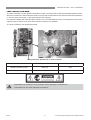
Supply from solar storage cylinder
Installations MUST conform to local
regulataions.
Refer to Rinnai manuals supplied
with appliances for important
installation information.
Outlets to Personal Hygiene areas
to be tempered to 50°C as per
AS/NZS 3500.4
IMPORTANT
Rinnai Smartstart Unit
Rinnai Continuous Flow Water
Heater - Gas Booster
Gas Supply
Manual Activation
Switch ONLY
(not supplied)
Water controllers
MUST NOT
be used!
Return Line
INSTALLATION - GAS BOOSTED SYSTEMS
SYSTEM USING RINNAI SMARTSTART
EVT Split System Operation and Installation Manual
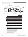
INSTALLATION - GAS BOOSTED SYSTEMS
GAS BOOSTER CLEARANCES
Figure 6.2 from AS/NZS5601 is reproduced below. It was current at the time of printing, but may have been
superseded. It is the installer’s responsibility to ensure that current requirements are met.
Flue terminal
Fan assisted flue appliance only
Ref.
Gas meter
(OHFWULFLW\PHWHURUIXVHER[
Mechanical air inlet
Min. clearances (mm)
Natural draft Fan assisted
Item
Below eaves, balconies and other projections:
Appliances up to 50 MJ/h input
300
Appliances over 50 MJ/h input
500
30 0
b
From the ground, above a balcony or other surface *
300
300
c
500
30 0
d
Front a return wall or external corner *
From a gas meter (M) (see 5.11.5.9 for vent terminal location of regulator )
(see Table 6.6 for New Zealand requirements)
1000
1000
e
From an electricity meter or fuse box (P) †
500
500
f
From a drain pipe or soil pipe
150
75
g
Horizontally from any building structure* = or obstruction facing a terminal
500
500
h
From any other flue terminal , cowl, or combustion air intake †
500
300
+RUL]RQWDOO\IURPDQRSHQDEOHZLQGRZGRRUQRQPHFKDQLFDODLULQOHWRUDQ\RWKHURSHQLQJLQWRDEXLOGLQJ
ZLWKWKHH[FHSWLRQRIVXEIORRUYHQWLODWLRQ
a
j
Appliances up to 150 MJ/h input *
500
3 00
Appliances over 150 MJ/h input up to 200 MJ/h input *
1500
300
Appliances over 200 MJ/h input up to 250 MJ/h input *
1500
500
Appliances over 250 MJ/h input *
1500
1500
1500
$OOIDQDVVLVWHGflue appliances , in the direction of discharge
k
n
200
1500
1 000
From a mechanical air inlet, including a spa blower
9HUWLFDOO\EHORZDQRSHQDEOHZLQGRZQRQPHFKDQLFDODLULQOHWRUDQ\RWKHURSHQLQJLQWRDEXLOGLQJZLWKWKH
H[FHSWLRQRIVXEIORRUYHQWLODWLRQ
Space heaters up to 50 MJ/hr input
150
2WKHUappliances up to 50 MJ/hr input
500
50 0
Appliances over 50 MJ/h input and up to 150 MJ/h input
1000
1000
1500
1500
Appliances over 150 MJ/h input
XQOHVVappliance is certified for closer installation
3URKLELWHGDUHDEHORZHOHFWULFLW\PHWHURUIXVHER[H[WHQGVWRJURXQGOHYHO
150
NOTES:
1
Where dimensions c, j or k cannot be achieved an equivalent horizontal distance
measured diagonally from the nearest discharge point of the terminal to the opening
may be deemed by the Technical Regulator to comply.
2
3
See Clause 6.9.4 for restrictions on a flue terminal under a covered area.
See Figure J3 for clearances required from a flue terminal to an LP Gas cylinder.
$ flue terminal is considered to be a source of ignition.
4
For appliance s not addressed above acceptance should be obtained from the Technical Regulator.
FIGURE 6.2 LQSDUW0,1,080&/($5$1&(65(48,5(')25%$/$1&(')/8(7(50,1$/6)$1$66,67('
)/8(7(50,1$/652206($/('$33/,$1&(7(50,1$/6$1'23(1,1*62)287'225$33/,$1&(6
Rinnai
34
EVT Split System Operation and Installation Manual
INSTALLATION - GAS BOOSTED SYSTEMS
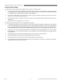
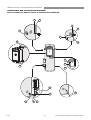
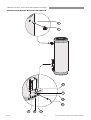
GAS BOOSTER MOUNTING
Step 1.
Mount
upper
mounting
bracket
using
template
provided.
(SG175,
ESG175,
SG215
&
ESG215
are
factory
mounted).
Step 2.
Fix
lower
mounting
bracket
to
Booster
using
screws
provided.
Step 3.
Hang booster on bracket and secure with
screws provided.
Step 4.
Secure lower mounting bracket to cylinder
using screws provided.
If the gas booster is not mounted on the storage cylinder, ensure that the wall or structure on which it is to be
mounted is capable of supporting the weight of the appliance and associated pipe work. Refer to the table on page
IRULQGLYLGXDOJDVERRVWHUZHLJKWV)RUJDVERRVWHUVLQVWDOOHGRQHOHYDWHGVWUXFWXUHVRUXQGHUÀRRUVVSHFL¿F
UHTXLUHPHQWVDSSO\UHIHUWR$61=6IRUGHWDLOV/RFDWLRQRIJDVERRVWHUÀXHWHUPLQDOPXVWEHLQDFFRUGDQFH
with AS/NZS 5601. Refer page 34.
Rinnai
35
EVT Split System Operation and Installation Manual
INSTALLATION - GAS BOOSTED SYSTEMS
COMPONENTS AND INSTALLATION DIAGRAMS
*ODVV/LQHG6*(6*6*RU(6*ZLWK6*3.,7$
2
1
3
13
10
3
15
12
16
14
11
17
14
16
15
11
8
3
Rinnai
6
12
5
36
EVT Split System Operation and Installation Manual
INSTALLATION - GAS BOOSTED SYSTEMS
*ODVV/LQHG6*(6*6*RU(6*ZLWK6*3.,7$
,WHPV6XSSOLHGZLWK&\OLQGHU
1
,WHPV6XSSOLHGZLWK6*3.,7$FRQW
1
PTR Valve
2
92501190
11
1
1
Adaptor R ¾ x Rp ½
3
Pump & Controller Assembly
3
Nipple R ¾
16
12
2
Gas Booster Mounting Brackets
1 x tabs bent
1 x tabs unbent
39001738
includes:
2 x ½” Kinco nut & olive
Flow control valve
Non return valve
Temperature sensor lead
Pump
Control Box
11001042
27801713
31002710
30001754
31002703
1
Temperature Sensor with 2 m lead
Part of Pump and Controller Assembly,
but shown separately for clarity in diagrams
26601098
26601096
31002710
,WHPV6XSSOLHGZLWK6*3.,7$
13
5
¾ Kinco Olive
6
33001011
14
1
¾ Kinco Nut
8
-
Cold Inlet Copper T
11603921
Fibre Washer ¾
17401008
Screws
22601048
Insulated Flexi Pipe 890 mm
11601070
$GDSWRU5Sô[*ôÀH[L
1
10
17
1
1
Warranty booklet
15401041
MAY BE OLD VERSION - USE BOOKLET
SUPPLIED IN EVAC TUBE INSTALL KIT
Rinnai
1
1
Operation and Installation Manual 15401023
USE MANUAL 15401100 INSTEAD
-
(OERZô5S[ô*ÀH[L
2
16801018
15
-
2
1
1
STC form
15401023
MAY BE OLD VERSION - USE FORM
SUPPLIED IN EVAC TUBE INSTALL KIT
37
EVT Split System Operation and Installation Manual
INSTALLATION - GAS BOOSTED SYSTEMS
Glass LineG6*6/(6*6/6*6/RU(6*6/ZLWK6*3.,T$
Rinnai
38
EVT Split System Operation and Installation Manual
INSTALLATION - GAS BOOSTED SYSTEMS
Glass LineG6*6/(6*6/6*6/RU(6*6/ZLWK6*3.,7$
,WHPV6XSSOLHGZLWK&\OLQGHU
1
,WHPV6XSSOLHGZLWK6*3.,7$FRQW
13
1
PTR Valve
2
1
92501190
14
1
Fibre Washer ¾
17401008
Insulated Flexi Pipe 1080 mm
11601069
2
Adaptor R ¾ x Rp ½
3
(OERZô5S[ô*ÀH[L
3
Adaptor R¾ x Rp¾
,WHPV6XSSOLHGZLWK6*3.,7$
4
15
1
R¾ Nipple
8
17201005
16
1
Cold Inlet Copper T
9
2
Gas Booster Mounting Brackets
1 x tabs bent
1 x tabs unbent
11603921
17
1
G3/4 (Comp) x R ¾ union
-
26601098
26601096
1
32201713
-
11
1
$GDSWRU5Sô[*ôÀH[L
Screws
22601048
4
1
1
Operation and Installation Manual 15401023
USE MANUAL 15401100 INSTEAD
Pump & Controller Assembly
39001739
includes:
2 x ½” Kinco nut & olive
Flow control valve
Non return valve
Temperature sensor lead
Pump
Control Box
-
11001033
27801713
31002710
30001754
31002703
Warranty booklet
15401041
MAY BE OLD VERSION - USE BOOKLET
SUPPLIED IN EVAC TUBE INSTALL KIT
12
1
1
1
STC form
15401023
MAY BE OLD VERSION - USE FORM
SUPPLIED IN EVAC TUBE INSTALL KIT
Temperature Sensor with 2 m lead
Part of Pump and Controller Assembly,
but shown separately for clarity in diagrams
-
31002710
Rinnai
1
Gas Booster Mounting Template
39
15401034
EVT Split System Operation and Installation Manual
INSTALLATION - GAS BOOSTED SYSTEMS
6WDLQOHVV6WHHO*DV%RRVWZLWK86.,7$
1
3
2
3
4
14
5
3
6
7
14
11
11
4
10
7
6
13
12
8
Rinnai
9
3
40
EVT Split System Operation and Installation Manual
INSTALLATION - GAS BOOSTED SYSTEMS
6WDLQOHVV6WHHO*DV%RRVWHGZLWK86.,7$
,WHPV6XSSOLHGZLWK&\OLQGHU
1
2
3
4
5
6
8
1
PTR Valve
11004784
Adaptor R ¾ x Rp ½
19801004
1
9
10
13
1
T ¾ Rp
19001011
R¾ Nipple
17201005
$GDSWRU5ôWR*ôÀH[L
11
32201713
Pump & Controller Assembly
39001739
1
includes:
2 x ½” Kinco nut & olive
Flow control valve
Non return valve
Temperature sensor lead
Pump
Control Box
2
17401008
12
1
-
6
1
Insulated Flexi Pipe 1080 mm
11601069
Temperature Sensor
Sheath 250 mm
10204721
11001033
27801713
31002710
30001754
31002703
Temperature Sensor with 2 m lead
Part of Pump and Controller Assembly,
but shown separately for clarity in diagrams
31002710
Screws
22601048
1
-
1
Operation and Installation Manual 15401023
USE MANUAL 15401100 INSTEAD
1
1
2
14
Warranty booklet
15401041
MAY BE OLD VERSION - USE BOOKLET
SUPPLIED IN EVAC TUBE INSTALL KIT
Gas Booster Mounting Brackets
1 x tabs bent
1 x tabs unbent
26601098
26601096
Screws
22601048
8
-
1
STC form
15401023
MAY BE OLD VERSION - USE FORM
SUPPLIED IN EVAC TUBE INSTALL KIT
1
Gas Booster Mounting Template
Rinnai
G3/4 (Comp) x R ¾ union
1
1
-
-
11603921
2
(OERZô5S[ô*ÀH[L
-
Cold Inlet Copper T
2
Fibre Washer ¾
7
,WHPV6XSSOLHGLQ86.,7$
15401040
41
EVT Split System Operation and Installation Manual
INSTALLATION - GAS BOOSTED SYSTEMS
INSTALLATION PROCEDURE
1.
,QVWDOO6RODU&ROOHFWRUV
Position and install the solar collectors in accordance with the section ‘Installation - Evacuated Tubes’ on
page 21.
3RVLWLRQ6WRUDJH&\OLQGHU
Position the hot water storage cylinder on a level base in accordance with the section ‘Storage Cylinder
Location’ on page 16.
&RQQHFW3759DOYH
Connect the PTR Valve in the location shown in the relevant diagram on pages 36 to 41. Leave the valve
RXWOHWSRLQWLQJGRZQ7LJKWHQWKHYDOYHXVLQJWKHVSDQQHUÀDWVQHYHUXVHWKHYDOYHERG\
The PTR Valve must be adequate for the thermal loading applied to the storage cylinder. In the case of gas
ERRVWHG V\VWHPV WKH WKHUPDO ORDG LV DSSOLHG RQO\ E\ WKH VRODU FROOHFWRUV 7KH FRQWLQXRXV ÀRZ KRW ZDWHU
heater does not apply thermal load to the storage cylinder. The potential solar output for the solar collectors
at PTR Valve relief conditions is listed in the table on page 9.
7KH3759DOYHSUHVVXUHUDWLQJVYDU\DFFRUGLQJWKHF\OLQGHUVSHFL¿FDWLRQV7KHPD[LPXPKHDWHULQSXWUDWLQJ
is 10.0 kW. The PTR valve rating MUST EXCEED the total input from the solar collectors. If it does not, the
PTR valve MUST be exchanged for a model of higher capacity.
For example, for a gas boosted solar system with 2 x EVT20A collectors, the thermal load is 2 x 1.63 = 3.26
N:7KLVLVOHVVWKDQN:KHQFHWKHVXSSOLHG375YDOYHLVRIVXI¿FLHQWFDSDFLW\
8VH7HÀRQWKUHDGWDSHRQWKHYDOYHQHYHUXVHKHPSRURWKHUVHDOLQJPDWHULDOV(QVXUHWKHWDSHGRHVQRW
protrude past the end of the thread, which could result in it hanging over the end of the thread and blocking
the water passage through the valve.
0RXQW*DV%RRVWHU
Mount the gas booster in accordance with the section ‘Gas Booster Mounting’ on page 35.
&RQQHFW)LWWLQJVDQG0RXQW3XPS$VVHPEO\
&RQQHFW ¿WWLQJV DQG SLSH ZRUN DV VKRZQ LQ WKH UHOHYDQW GLDJUDP RQ SDJHV WR 5HPRYH FRYHU RI
pump box and attach pump box to cylinder using screws provided. DO NOT connect the power lead to power
supply at this stage.
6HW)URVW3URWHFWLRQ0RGH
Adjust Dip Switches on Solar Controller to give the required frost protection. (Refer page 19).
,QVWDOODQG&RQQHFW)ORZDQG5HWXUQ3LSH:RUN
&RQQHFWÀRZDQGUHWXUQSLSHZRUNEHWZHHQVWRUDJHF\OLQGHUDQGVRODUFROOHFWRU(QVXUHWKDWVXLWDEOHSLSHDQG
insulation is used as described in the section ‘Water Pipes’ on page 17.
A heat trap is recommended on the return line from the cylinder if the pipework is to rise vertically to prevent
heat losses due to the thermosyphoning of hot water from the tank.
Hot water return
from collectors
250 mm
Heat Trap
Rinnai
42
EVT Split System Operation and Installation Manual
INSTALLATION - GAS BOOSTED SYSTEMS
8.
&RQQHFW7HPSHUDWXUH6HQVRU/HDGV
7KHKRWORQJHUWHPSHUDWXUHVHQVRUOHDGVKRXOGEH¿WWHGLQWRWKH
air bleed / hot sensor lead assembly at the collector hot return
connection as shown on page 31. It must be sealed in place
with thermoplastic putty or silicone.
Run the lead down the solar return pipe and connect it to the
connection within the pump and controller assembly as shown in
the diagram. Ensure the lead is protected from light.
7KHFROGVKRUWHUWHPSHUDWXUHVHQVRUOHDGVKRXOGEH¿WWHGDV
shown in the relevant diagram on pages 36 to 40.
hot sensor connection
in pump box.
cold sensor connection
in pump box.
hot sensor lead
connection
cold sensor lead
connection
Ensure the lead is protected from light. It must be sealed in place
with thermoplastic putty or silicone. The plug is then connected
to the pump and controller assembly as shown in the diagram.
Replace Pump Assembly Cover.
NOTE
IT IS IMPORTANT THAT THESE PROBES ARE INSTALLED AS SPECIFIED. FAILURE TO DO SO
WILL LEAD TO MALFUNCTION OR LACK OF HOT WATER
&ROG:DWHU6XSSO\
&RQQHFWFROGZDWHUVXSSO\WRWKHLQOHWµ7¶(QVXUHWKDWWKHUHOHYDQWYDOYHVDUH¿WWHGDVGHVFULEHGLQWKHVHFWLRQ
‘Valves and Fittings’ on page 20.
3XUJHWKHFROGZDWHUVXSSO\OLQHVWRUHPRYHDLUDQGVZDUIEHIRUH¿QDOFRQQHFWLRQ
5HOLHI'UDLQ/LQHV
,QGHSHQGHQWPPFRSSHUSLSHVPXVWEH¿WWHGWRWKHGUDLQRXWOHWVRIWKH375DQG(&9(DFKSLSHPXVW
be open to atmosphere and run with a continual downward grade in a frost free environment to a visible
discharge point. Drain lines must not exceed 9 metres in length.
Valves or other restrictions must not be placed in the relief valve drain outlet line.
NOTE
Some water will drip from the drain lines during heating of the water in the storage cylinder. It is
recommended to discharge directly above a drain.
11. +RW:DWHU'LVFKDUJH
Connect the hot water outlet of the gas booster to the pipe work supplying hot water to the premises.
WARNING
A temperature limiting device may be required as detailed in the section ‘Hot Water Delivery
Temperature’ on page 18.
&RQQHFW*DVWR%RRVWHU
Connect a suitable gas supply and isolating valve to the gas booster. Follow instructions supplied with gas
booster. Keep gas booster isolated at this stage.
Rinnai
43
EVT Split System Operation and Installation Manual
INSTALLATION - GAS BOOSTED SYSTEMS
FILLING THE SYSTEM
CAUTION
Ensure building occupants are warned to stay clear of the solar system components, building perimeter
and roof since hot water or steam may be discharged from pipes or components.
1.
Ensure the electric power supplies to the water heater and pump kit are switched ‘OFF’.
2.
(QVXUHWKHJDVVXSSO\WRWKHFRQWLQXRXVÀRZZDWHUKHDWHULVLVRODWHG
3.
Turn ‘ON’ the hot water tap at the sink. Open the stop cock in the cold water mains supply line.
4.
7KHHQWLUHV\VWHPZLOOQRZEH¿OOHGZLWKFROGZDWHU0RVWDLUZLOOEHGLVSHOOHGWKURXJKWKHWDS6RPHDLUQHHGV
to be bled from the air bleed valve on the collectors.
5.
7XUQµ2))¶WKHKRWWDSDWWKHVLQNZKHQZDWHUÀRZVIUHHO\ZLWKRXWDLUEXEEOHVRUDLUEXUVWV&KHFNDOOFRQQHFWLRQV
IRUOHDNDJHDQGWLJKWHQLIQHFHVVDU\7KLVDSSOLHVHVSHFLDOO\WR¿WWLQJVLQSRVLWLRQVQRWHDVLO\DFFHVVHGVXFK
as near the solar collectors. Operate the easing gear of both the PTR and ECV valves at the storage cylinder
to ensure these valves are functional.
CAUTION
,IOHDNVDUHGHWHFWHGWKHV\VWHPPXVWEHGUDLQHGDQGOHDNVUHSDLUHGEHIRUHWKHV\VWHPLVUH¿OOHG,I
this is necessary, cover the solar collectors with packaging cardboard or a tarp to prevent them from
KHDWLQJZKLFKFRXOGUHVXOWLQVWHDPRUKRWZDWHUEHLQJGLVFKDUJHGIURP¿WWLQJV
&+(&.,1*62/$5380323(5$7,21
1.
Ensure hot and cold sensors are connected as shown on page 43.
2.
Activate power supply.
3.
Pumps will operate when solar energy is available to be collected. Pump operation can be checked by placing
the end of a screw driver to the pump body and the other end of the screw driver near your ear.
ADJUSTING FLOW CONTROL VALVE
NOTE
If the solar pump does not activate the system can still be commissioned as detailed in these
instructions, but solar preheating will not be available until the pump and controller operate.
7KHSXUSRVHRIWKHÀRZFRQWUROYDOYHLVWRDOORZWKHZDWHUÀRZUDWHWKURXJKWKH
evacuated tube header and storage cylinder to be controlled to optimise the
SHUIRUPDQFHRIWKHV\VWHP7KHRSWLPXPÀRZUDWHIRUWKHV\VWHPZLOOGHSHQGRQ
the number of evacuated tubes and the type of storage cylinder.
7KHÀRZFRQWUROYDOYHQHHGVWREHDGMXVWHGZKLOHWKHSXPSLVRSHUDWLQJ7KHÀRZ
UDWHYDOYHLVUHDGDWWKHERWWRPRIWKHEDIÀHÀRDWDVVKRZQ8VLQJDÀDWEODGHG
screw driver turn the screw on the valve until the value from the table below is
achieved
Rinnai
Number of Evacuated Tubes
Suggested Flowrate
(l/min)
20
0.5
25
0.55
30
0.6
40
0.65
44
EVT Split System Operation and Installation Manual
INSTALLATION - GAS BOOSTED SYSTEMS
35(62/$5+($7,1*&+(&.6
Before commencing solar heating of the water in the system ensure the following actions have been completed:
Solar Collectors
1.
Are the solar collectors installed with the correct slope and orientation to the sun?
2.
,VWKHLQVWDOODWLRQ¿QLVKHGQHDWO\ZLWKWKHURRIPDGHJRRGDOOWLOHVDQGÀDVKLQJVLQSODFH"
3.
Are the bolts tight on the roof framework?
4.
$UHDOOVRODUFROOHFWRUVWUDSV¿WWHGDQGFRUUHFWO\DQFKRUHGWRWKHURRIVWUXFWXUH"
5.
If leak testing completed and successful, have any covers been removed from the solar collectors?
6.
Has operation of the solar pump been checked?
7. Have the hot and cold sensors and leads been positioned and connected correctly?
Gas Booster
1.
Ensure the gas supply is isolated. Remove the test point screw located on the gas inlet connection and attach
a pressure gauge.
2.
Turn on the electrical power to the gas booster only (not the solar pump kit) and turn on the gas supply.
3.
Ensure the cold water inlet (‘trio’) valve on the storage cylinder inlet is open. Open all available hot water taps.
4.
Operate ALL other gas appliances at their maximum gas rate, in accordance with manufacturers instructions.
Ensure building occupants do not have access to hot water outlets during this procedure.
CAUTION
5.
With all gas appliances in operation at the maximum gas rate, the pressure should read between 1.13 - 3.0
kPa on Natural Gas. On LPG the pressure should be 2.75 - 3.0 kPa. If the pressure is lower, the gas supply
LVLQDGHTXDWHDQGWKHDSSOLDQFHZLOOQRWRSHUDWHWRVSHFL¿FDWLRQ,WLVWKHLQVWDOOHUVUHVSRQVLELOLW\WRFKHFNWKH
gas meter, service regulator and pipe work for correct operation/ sizing & rectify as required. Note that the
gas regulator on the appliance is electronically controlled and factory pre-set. Under normal circumstances
it DOES NOT need adjustment during installation. Make adjustments only if the gas booster is not operating
correctly and all other possible causes for incorrect operation have been eliminated. Instructions for gas
pressure setting are located in the pocket behind the front cover of the gas booster.
6.
Close the hot water taps including the shower.
7.
Close the cold water inlet (‘trio’) valve on the storage cylinder inlet and inspect and clean the strainer. Repeat
for the strainer connected at the inlet of the gas booster. This procedure may need to be repeated to ensure
the strainers remains clear, especially on new installations.
&RQ¿UP WKH KRW ZDWHU GHOLYHU\ WHPSHUDWXUH IURP WKH JDV ERRVWHU7KLV LV GRQH E\ FKHFNLQJ WKH KRW ZDWHU
delivery temperature at an untempered outlet close to the water heater. This is usually the hot water outlet in
the kitchen. The untempered hot water delivery should be between 65°C & 70°C.
Temperature Limiting Devices
8.
1.
Commission any temperature limiting devices in accordance with the instructions supplied by the manufacturer.
2.
&RQ¿UPWKHKRWZDWHUGHOLYHU\WHPSHUDWXUHDWDWHPSHUHGZDWHURXWOHW7HPSHUHGZDWHURXWOHWVVKRXOGEH
those supplying areas primarily used for the purposes of personal hygiene such as bathrooms. The hot
water delivery temperature should not exceed 50°C or 45°C as detailed in the section ‘Hot Water Delivery
Temperature’ on page 18.
Rinnai
45
EVT Split System Operation and Installation Manual
INSTALLATION - GAS BOOSTED SYSTEMS
SOLAR HEATING
1.
Remove any cardboard or tarp covers that may have been placed over the solar collectors to prevent them
from heating water during installation and commissioning.
2.
Activate electrical power to both the gas booster and solar pump and controller. Solar heating of the water in
WKHF\OLQGHUZLOOQRZFRPPHQFHZKHQVXI¿FLHQWVRODUUDGLDWLRQLVDYDLODEOH
FINISHING THE INSTALLATION
1.
After testing is completed explain to the householder the functions and operation of solar water heater
components and the importance of carrying out Maintenance as per separate warranty document.
2.
Complete the installation record at the back of the manual.
/HDYHWKLVPDQXDODQGWKHZDUUDQW\ERRNOHWZLWKWKHKRXVHKROGHU.
DRAINING INSTRUCTIONS
1.
The power supply to the gas booster and pump controller must be switched off and fuse(s) removed.
2.
Close the cold water mains supply stop cock.
3.
Open a hot tap to relieve pressure.
4.
Disconnect the hot outlet near the top of the storage cylinder.
5.
Disconnect the cold inlet near the bottom of the storage cylinder.
6.
'LVFRQQHFWWKHFRQQHFWLRQEHWZHHQWKHVRODUµÀRZSLSH¶DQGVRODUSXPS
7.
Disconnect the connection between the solar ‘return pipe’ and the cylinder.
8.
The cylinder and solar collectors will now drain completely
Rinnai
46
EVT Split System Operation and Installation Manual
INSTALLATION - ELECTRIC BOOSTED SYSTEMS
OVERVIEW OF SYSTEM COMPONENTS
The range of electric boosted solar hot water systems include all the components shown on pages 48 to 51.
(refer to the appropriate diagram depending on cylinder type/size and kit).
7KHSXPSNLWDQGDVVRFLDWHGSOXPELQJFRQQHFWLRQVDUHIDFWRU\SUHDVVHPEOHG$OORWKHUFRPSRQHQWVDQG¿WWLQJV
will require connection on site.
ELECTRIC SUPPLY
(OHFWULFDOFRQQHFWLRQPXVWEHFDUULHGRXWE\DTXDOL¿HGSHUVRQDQGLQDFFRUGDQFHZLWK$61=6µ:LULQJ5XOHV¶
and local authority requirements.
All electrically boosted solar hot water heating elements must be connected to an independent, fused, AC 240V 50
Hz power supply with an isolating switch installed at the switch board. Ensure the household wiring to the system is
FDSDEOHRIZLWKVWDQGLQJWKHV\VWHPHOHFWULFDOORDGUHIHUWRVSHFL¿FDWLRQVIRUHOHFWULFDOORDGGHWDLOV7ZLQHOHPHQW
models are factory wired for ‘non’ simultaneous’ operation.
The solar pump kit requires an AC 240V power supply from a 10A earthed power point adjacent to the storage
cylinder. For outdoor installations this power point must be weatherproof. This power supply must be independent
from the power supply to any heating elements.
HOT WATER STORAGE AND DELIVERY TEMPERATURE
Australian Standards require a minimum storage cylinder thermostat set point of 60°C.
Rinnai
47
EVT Split System Operation and Installation Manual
INSTALLATION - ELECTRIC BOOSTED SYSTEMS
*ODVV/LQHG(OHFWULF%RRVWHG6\VWHPVZLWK86.,7$
2
1
3
3
11
12
8
3
Rinnai
9
48
EVT Split System Operation and Installation Manual
INSTALLATION - ELECTRIC BOOSTED SYSTEMS
*ODVV/LQHG(OHFWULF%RRVWHG6\VWHPVZLWK86.,7$
,WHPV6XSSOLHGZLWK&\OLQGHU
1
8
1
PTR Valve
2
,WHPV6XSSOLHGLQ86.,7$
1
92501190
9
1
11603921
G3/4 (Comp) x R ¾ union
32201713
Pump & Controller Assembly
39001739
1
Adaptor R ¾ x Rp ½
3
Cold Inlet Copper T
3
Adaptor R¾ x Rp¾
11
1
includes:
2 x ½” Kinco nut & olive
Flow control valve
Non return valve
Temperature sensor lead
Pump
Control Box
12
1
-
6
Temperature Sensor with 2 m lead
Part of Pump and Controller Assembly,
but shown separately for clarity in diagrams
31002710
Screws
-
11001033
27801713
31002710
30001754
31002703
22601048
1
Operation and Installation Manual 15401023
USE MANUAL 15401100 INSTEAD
-
1
Warranty booklet
15401041
MAY BE OLD VERSION - USE BOOKLET
SUPPLIED IN EVAC TUBE INSTALL KIT
-
1
STC form
15401023
MAY BE OLD VERSION - USE FORM
SUPPLIED IN EVAC TUBE INSTALL KIT
Rinnai
49
EVT Split System Operation and Installation Manual
INSTALLATION - ELECTRIC BOOSTED SYSTEMS
6WDLQOHVV6WHHO(OHFWULF%RRVWHGZLWK86.,7$
2
1
11
4
10
12
8
Rinnai
9
3
50
EVT Split System Operation and Installation Manual
INSTALLATION - ELECTRIC BOOSTED SYSTEMS
6WDLQOHVV6WHHO*DV%RRVWHGZLWK86.,7$
,WHPV6XSSOLHGZLWK&\OLQGHU
1
8
1
PTR Valve
2
3
4
1
11004784
9
1
Hot Outlet T
19001018
T ¾ Rp
19001011
Cold Inlet Copper T
11603921
G3/4 (Comp) x R ¾ union
32201713
Pump & Controller Assembly
39001739
1
1
11
1
R¾ Nipple
10
,WHPV6XSSOLHGLQ86.,7$
1
17201005
includes:
2 x ½” Kinco nut & olive
Flow control valve
Non return valve
Temperature sensor lead
Pump
Control Box
1
Temperature Sensor
Sheath 250 mm
10204721
12
1
-
6
Temperature Sensor with 2 m lead
Part of Pump and Controller Assembly,
but shown separately for clarity in diagrams
31002710
Screws
-
11001033
27801713
31002710
30001754
31002703
22601048
1
Operation and Installation Manual 15401023
USE MANUAL 15401100 INSTEAD
-
1
Warranty booklet
15401041
MAY BE OLD VERSION - USE BOOKLET
SUPPLIED IN EVAC TUBE INSTALL KIT
-
1
STC form
15401023
MAY BE OLD VERSION - USE BOOKLET
SUPPLIED IN EVAC TUBE INSTALL KIT
Rinnai
51
EVT Split System Operation and Installation Manual
INSTALLATION - ELECTRIC BOOSTED SYSTEMS
INSTALLATION PROCEDURE
1.
,QVWDOO6RODU&ROOHFWRUV
Position and install the solar collectors in accordance with the section ‘Installation - Evacuated Tubes’ on
page 21.
3RVLWLRQ6WRUDJH&\OLQGHU
Position the hot water storage cylinder on a level base in accordance with the section ‘Storage Cylinder
Location’ on page 16.
&RQQHFW3759DOYH
Connect the PTR Valve in the location shown in the relevant diagram on pages 48 to 51.
/HDYHWKHYDOYHRXWOHWSRLQWLQJGRZQ7LJKWHQWKHYDOYHXVLQJWKHVSDQQHUÀDWVQHYHUXVHWKHYDOYHERG\
The PTR Valve must be adequate for the thermal loading applied to the storage cylinder. In the case of gas
ERRVWHG V\VWHPV WKH WKHUPDO ORDG LV DSSOLHG RQO\ E\ WKH VRODU FROOHFWRUV 7KH FRQWLQXRXV ÀRZ KRW ZDWHU
heater does not apply thermal load to the storage cylinder. The potential solar output for the solar collectors
at PTR Valve relief conditions is listed in the table on page 10.
7KH3759DOYHSUHVVXUHUDWLQJVYDU\DFFRUGLQJWKHF\OLQGHUVSHFL¿FDWLRQV7KHPD[LPXPKHDWHULQSXWUDWLQJ
is 10.0 kW. The PTR valve rating MUST EXCEED the total input from the solar collectors. If it does not, the
PTR valve MUST be exchanged for a model of higher capacity.
For example, for an electric boosted solar system with a 3.6 kW element and 2 x EVT20A collectors, the
thermal load is 2 x 1.63 + 3.6 = 6.86 kW. This is less than 10.0 kW, hence the supplied PTR valve is of
VXI¿FLHQWFDSDFLW\
8VH7HÀRQWKUHDGWDSHRQWKHYDOYHQHYHUXVHKHPSRURWKHUVHDOLQJPDWHULDOV(QVXUHWKHWDSHGRHVQRW
protrude past the end of the thread, which could result in it hanging over the end of the thread and blocking
the water passage through the valve.
&RQQHFW)LWWLQJVDQG0RXQW3XPS$VVHPEO\
&RQQHFW ¿WWLQJV DQG SLSH ZRUN DV VKRZQ LQ WKH UHOHYDQW GLDJUDP IURP SDJH WR 5HPRYH FRYHU RI
pump box and attach pump box to cylinder using screws provided. DO NOT connect the power lead to power
supply at this stage.
6HW)URVW3URWHFWLRQ0RGH
Adjust Dip Switches on Solar Controller to give the required frost protection. (Refer to the section ‘Frost
Protection Mode’ on page 19.).
,QVWDOODQG&RQQHFW)ORZDQG5HWXUQ3LSH:RUN
&RQQHFWÀRZDQGUHWXUQSLSHZRUNEHWZHHQVWRUDJHF\OLQGHUDQGVRODUFROOHFWRU(QVXUHWKDWVXLWDEOHSLSHDQG
insulation is used as described in the section ‘Water Pipes’ on page 17.
A heat trap is recommended on the return line from the cylinder if the pipework is to rise vertically to prevent
heat losses due to the thermosyphoning of hot water from the tank.
Hot water return
from collectors
250 mm
Heat Trap
Rinnai
52
EVT Split System Operation and Installation Manual
INSTALLATION - ELECTRIC BOOSTED SYSTEMS
&RQQHFW7HPSHUDWXUH6HQVRU/HDGV
7KHKRWORQJHUWHPSHUDWXUHVHQVRUOHDGVKRXOGEH¿WWHGLQWRWKH
pocket on the evacuated tube header as shown on page 31. It
must be sealed in place with thermoplastic putty or silicone.
Run the lead down the solar return pipe and connect it to the
connection within the pump and controller assembly as shown in
the diagram. Ensure the lead is protected from light.
7KHFROGVKRUWHUWHPSHUDWXUHVHQVRUOHDGVKRXOGEH¿WWHGDV
shown in the relevant diagram on pages 48 to 51.
hot sensor connection
in pump box.
cold sensor connection
in pump box.
hot sensor lead
connection
cold sensor lead
connection
Ensure the lead is protected from light. It must be sealed in place
with thermoplastic putty or silicone. The plug is then connected
to the pump and controller assembly as shown in the diagram.
Replace Pump Assembly Cover.
NOTE
8.
IT IS IMPORTANT THAT THESE PROBES ARE INSTALLED AS SPECIFIED. FAILURE TO DO SO
WILL LEAD TO MALFUNCTION OR LACK OF HOT WATER
&ROG:DWHU6XSSO\
Connect cold water supply to the inlet ‘T’. Ensure that the relevant valves as described in the section ‘Valves
DQG)LWWLQJV¶RQSDJHDUH¿WWHG
3XUJHWKHFROGZDWHUVXSSO\OLQHVWRUHPRYHDLUDQGVZDUIEHIRUH¿QDOFRQQHFWLRQ
5HOLHI'UDLQ/LQHV
,QGHSHQGHQWPPFRSSHUSLSHVPXVWEH¿WWHGWRWKHGUDLQRXWOHWVRIWKH375DQG(&9(DFKSLSHPXVW
be open to atmosphere and run with a continual downward grade in a frost free environment to a visible
discharge point. Drain lines must not exceed 9 metres in length.
Valves or other restrictions must not be placed in the relief valve drain outlet line.
NOTE
Some water will drip from the drain lines during heating of the water in the storage cylinder. It is
recommended to discharge directly above a drain.
+RW:DWHU'LVFKDUJH
Connect the hot water outlet of the gas booster to the pipe work supplying hot water to the premises.
WARNING
A temperature limiting device may be required as detailed in the section ‘Hot Water Delivery
Temperature’ on page 18.
11. &RQQHFWWR(OHFWULFDO6XSSO\
Twin element storage cylinders are wired for non simultaneous operation. The electric supply should be ‘Off-Peak’
(overnight) to the bottom heating unit and continuous to the top heating unit.
The power supply to a single lower element model should be Off-Peak (overnight).
The power supply to a single mid element model can be either Off-Peak (overnight), extended Off-Peak (overnight
and day) or continuous, depending on the tariffs available from the local electricity supply authority. The Off-Peak
RYHUQLJKWSRZHUVXSSO\PLQLPLVHVWKHFRVWRIDQ\UHTXLUHGHOHFWULFERRVWLQJEXWPD\QRWSURYLGHVXI¿FLHQWKRW
water in periods of low solar gain. Discuss power supply requirements with the end user and electricity supply
authority as required.
Rinnai
53
EVT Split System Operation and Installation Manual
INSTALLATION - ELECTRIC BOOSTED SYSTEMS
Wiring Diagrams
Single Element
Twin Element
$ÀH[LEOHPPFRQGXLWLVUHTXLUHGIRUWKHHOHFWULFDOFDEOHWRWKHVWRUDJHF\OLQGHU7KHFRQGXLWLVWREHFRQQHFWHG
to the unit with a 20mm terminator. Connect the power supply wires directly to the terminal block and earth tab
connections ensuring there are no excess wire loops inside the front cover. Connections for twin element heaters
7ZLQ HOHPHQW KHDWHUV DUH ZLUHG IRU QRQ VLPXOWDQHRXV RSHUDWLRQ $ ÀH[LEOH PP FRQGXLW LV UHTXLUHG IRU WKH
electrical cable to the storage cylinder. All wiring passes through the lower entry. The conduit is to be connected
to the unit with a 20 mm terminator. A common neutral is used. Connect the power supply wires directly to the
terminal block and earth tab connections ensuring there are no excess wire loops inside the front cover.
Heating Element Thermostat Temperature Settings
Australian Standards require a minimum thermostat set point of 60°C to inhibit the growth of Legionella Pneumophilia
EDFWHULD 7KHVH VWDQGDUGV DOVR UHTXLUH WKDW WKH WKHUPRVWDW VHW SRLQW RI ZDWHU KHDWHUV ¿WWHG ZLWK DQ XSSHU RU
booster) element is at least 10°C below the thermostat set point of the lower element.
In the interests of durability, the thermostat set point for storage cylinders should not exceed 70°C. Hence, in
systems with a single heating element only the thermostat set point should be at least 60°C and no greater than
70°C. In systems with both a lower and upper (or booster) element, the thermostat set point of the lower element
should be between 60°C and 70°C and the upper element 50°C - 60°C.
Rinnai
54
EVT Split System Operation and Installation Manual
INSTALLATION - ELECTRIC BOOSTED SYSTEMS
FILLING THE SYSTEM
CAUTION
Ensure building occupants are warned to stay clear of the solar system components, building perimeter
and roof since hot water or steam may be discharged from pipes or components.
1.
Ensure the electric power supplies to the water heater and pump kit are switched ‘OFF’.
2.
(QVXUHWKHJDVVXSSO\WRWKHFRQWLQXRXVÀRZZDWHUKHDWHULVLVRODWHG
3.
Turn ‘ON’ the hot water tap at the sink. Open the stop cock in the cold water mains supply line.
4.
7KHHQWLUHV\VWHPZLOOQRZEH¿OOHGZLWKFROGZDWHU0RVWDLUZLOOEHGLVSHOOHGWKURXJKWKHWDS6RPHDLUQHHGV
to be bled from the air bleed valve on the collectors.
5.
7XUQµ2))¶WKHKRWWDSDWWKHVLQNZKHQZDWHUÀRZVIUHHO\ZLWKRXWDLUEXEEOHVRUDLUEXUVWV&KHFNDOOFRQQHFWLRQV
IRUOHDNDJHDQGWLJKWHQLIQHFHVVDU\7KLVDSSOLHVHVSHFLDOO\WR¿WWLQJVLQSRVLWLRQVQRWHDVLO\DFFHVVHGVXFK
as near the solar collectors. Operate the easing gear of both the PTR and ECV valves at the storage cylinder
to ensure these valves are functional.
CAUTION
,IOHDNVDUHGHWHFWHGWKHV\VWHPPXVWEHGUDLQHGDQGOHDNVUHSDLUHGEHIRUHWKHV\VWHPLVUH¿OOHG,I
this is necessary, cover the solar collectors with packaging cardboard or a tarp to prevent them from
KHDWLQJZKLFKFRXOGUHVXOWLQVWHDPRUKRWZDWHUEHLQJGLVFKDUJHGIURP¿WWLQJV
&+(&.,1*62/$5380323(5$7,21
1.
Ensure hot and cold sensors are connected as shown on page the section ‘Connect Temperature Sensor
Leads’ on page 53.
2.
Activate power supply.
3.
Pumps will operate when solar energy is available to be collected. Pump operation can be checked by placing
the end of a screw driver to the pump body and the other end of the screw driver near your ear.
ADJUSTING FLOW CONTROL VALVE
NOTE
If the solar pump does not activate the system can still be commissioned as detailed in these
instructions, but solar preheating will not be available until the pump and controller operate.
7KHSXUSRVHRIWKHÀRZFRQWUROYDOYHLVWRDOORZWKHZDWHUÀRZUDWHWKURXJKWKH
evacuated tube header and storage cylinder to be controlled to optimise the
SHUIRUPDQFHRIWKHV\VWHP7KHRSWLPXPÀRZUDWHIRUWKHV\VWHPZLOOGHSHQGRQ
the number of evacuated tubes and the type of storage cylinder.
7KHÀRZFRQWUROYDOYHQHHGVWREHDGMXVWHGZKLOHWKHSXPSLVRSHUDWLQJ7KHÀRZ
UDWHYDOYHLVUHDGDWWKHERWWRPRIWKHEDIÀHÀRDWDVVKRZQ8VLQJDÀDWEODGHG
screw driver turn the screw on the valve until the value from the table below is
achieved
Rinnai
Number of Evacuated Tubes
Suggested Flowrate
(l/min)
20
0.5
25
0.55
30
0.6
40
0.65
55
EVT Split System Operation and Installation Manual
INSTALLATION - ELECTRIC BOOSTED SYSTEMS
35(62/$5+($7,1*&+(&.6
Before commencing solar heating of the water in the system ensure the following actions have been completed:
Solar Collectors
1.
Are the solar collectors installed with the correct slope and orientation to the sun?
2.
,VWKHLQVWDOODWLRQ¿QLVKHGQHDWO\ZLWKWKHURRIPDGHJRRGDOOWLOHVDQGÀDVKLQJVLQSODFH"
3.
Are the bolts tight on the roof framework?
4.
$UHDOOVRODUFROOHFWRUVWUDSV¿WWHGDQGFRUUHFWO\DQFKRUHGWRWKHURRIVWUXFWXUH"
5.
If leak testing completed and successful, have any covers been removed from the solar collectors?
6.
Has operation of the solar pump been checked?
7. Have the hot and cold sensors and leads been positioned and connected correctly?
Electric Heating Elements
1.
In systems with a single heating element only has the thermostat set point been set to at least 60°C and no
greater than 70°C.
2.
In systems with both a lower and upper (or booster) element, has the thermostat set point of the lower
element been set to at least 60° and no greater than 70°. Has the upper element been set to 10° less than
the lower element?.
Temperature Limiting Devices
1.
Commission any temperature limiting devices in accordance with the instructions supplied by the manufacturer.
&RQ¿UPWKHKRWZDWHUGHOLYHU\WHPSHUDWXUHDWDWHPSHUHGZDWHURXWOHW7HPSHUHGZDWHURXWOHWVVKRXOGEH
those supplying areas primarily used for the purposes of personal hygiene such as bathrooms. The hot
water delivery temperature should not exceed 50°C or 45°C as detailed in the section ‘Hot Water Delivery
Temperature’ on page 18.
Solar Heating
2.
1.
Remove any cardboard or tarp covers that may have been placed over the solar collectors to prevent them
from heating water during installation and commissioning.
2.
Activate electrical power to both the gas booster and solar pump and controller. Solar heating of the water in
WKHF\OLQGHUZLOOQRZFRPPHQFHZKHQVXI¿FLHQWVRODUUDGLDWLRQLVDYDLODEOH
AUXILIARY ENERGY SUPPLY
1.
Connect the electrical element to the power supply (off peak if available).
2.
When the system is full of water turn on electrical supply to element.
FINISHING THE INSTALLATION
1.
After testing is completed explain to the householder the functions and operation of solar water heater
components and the importance of carrying out Maintenance as per separate warranty document.
2.
Complete the installation record at the back of the manual.
/HDYHWKLVPDQXDODQGWKHZDUUDQW\ERRNOHWZLWKWKHKRXVHKROGHU.
Rinnai
56
EVT Split System Operation and Installation Manual
INSTALLATION - ELECTRIC BOOSTED SYSTEMS
DRAINING INSTRUCTIONS
1.
The power supply to the element and pump controller must be switched off and fuse(s) removed.
2.
Close the cold water mains supply stop cock.
3.
Open a hot tap to relieve pressure.
4.
Disconnect the hot outlet near the top of the storage cylinder.
5.
Disconnect the cold inlet near the bottom of the storage cylinder.
6.
'LVFRQQHFWWKHFRQQHFWLRQEHWZHHQWKHVRODUµÀRZSLSH¶DQGVRODUSXPS
7.
Disconnect the connection between the solar ‘return pipe’ and the cylinder.
8.
The cylinder and solar collectors will now drain completely.
Rinnai
57
EVT Split System Operation and Installation Manual
Rinnai
58
EVT Split System Operation and Installation Manual
INSTALLATION - GAS BOOSTED SYSTEMS
Installer Details
Installers Name:
_______________________________________________________________________
Company Name:
_______________________________________________________________________
Company Address: ________________________________________________________________________
_______________________________________________________________________
________________________________________________________________________
Company Contact Details
Telephone:
________________________________________________________________________
Mobile Phone:
________________________________________________________________________
&HUWL¿FDWHRI&RPSOLDQFH&HUWL¿FDWLRQ1XPEHU
Authorised Persons - Licence Number:
BBBBBBBBBBBBBBBBBBBBBBBBBBBBBBBBBBBBBBBBBBBBB
___________________________________________________
Installers Signature:
_______________________________________________________________________
Installation Date:
_______________________________________________________________________
6\VWHP'HWDLOV
Storage Cylinder
Model Number : __________________________________________________________
Serial Number:
Solar Collector(s)
Model Number : __________________________________________________________
Serial Number:
Gas Booster
__________________________________________________________
__________________________________________________________
Model Number : __________________________________________________________
Serial Number:
__________________________________________________________
Installation Address: ________________________________________________________________________
_______________________________________________________________________
________________________________________________________________________
Rinnai
59
EVT Split System Operation and Installation Manual
Australia Pty. Ltd.
Internet: www.rinnai.com.au E-mail: [email protected]
ABN 74 005 138 769
Head Office
10-11 Walker Street,
Braeside, Victoria 3195
P.O. Box 460
Tel: (03) 9271 6625
Fax: (03) 9271 6622
National Help Line
Tel: 1300 555 545* Fax: 1300 555 655*
*Cost of a local call higher from mobile or public phones.
Hot Water Service Line
Tel: 1800 000 340
Rinnai has a Service and Spare Parts network with personnel who are fully trained
and equipped to give the best service on your Rinnai appliance. If your appliance
requires service, please call our National Help Line. Rinnai recommends that this
appliance be serviced every 3 years.
15401100
60
EVT Split System OIM Issue 1 - Aug 2013.