1
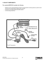
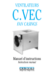
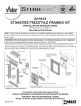
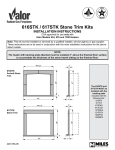
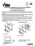
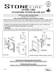
#555 CIRCULATING FAN KIT
INSTALLATION and OPERATING INSTRUCTIONS
CSA approved for use only with:
Valor model 530, RetroFire RF24 and Madrona MF28
Note: This kit must be installed or serviced by a qualified installer, service agency or the
gas supplier. These instructions are to be used in conjunction with the main installation
instructions for the above listed models.
WARNING: If the information in these instructions is not followed exactly, a fire or
explosion may result causing property damage, personal injury or loss of life.
GROUNDING: This power supply must be installed and grounded in accordance with
local codes, or in the absence of local codes, with the current Canadian Electrical Code
CSA C22.1. or in the USA the National Electrical Code ANSI/NFPA70 latest edition.
1. DESCRIPTION OF SYSTEM
The Models listed above have been designed to accommodate the installation of an air circulation
fan. Operated by a variable speed control and a thermally actuated switch, a fan is designed to
boost the natural convection through the heater; this may be a desirable feature dependent on
the fireplace location and room layout. The circulating fan may be installed before the heater
2. ELECTRICAL REQUIREMENTS
The fan kit requires a power supply of 120 Volts, 1 phase, 60 Hz. Full load current is less than
1 amp.
This power supply must be installed and grounded in accordance with local codes, or in the
absence of local codes, with the current Canadian Electrical Code CSA C22.1. or in the USA the
National Electrical Code ANSI/NFPA70 latest edition.
4000510/02
© 2005, Miles Industries Ltd. All rights reserved.
3. FAN KIT COMPONENTS
The complete #555CFK Kit contains the following:
•
•
•
Blower & motor unit assembled to blower mounting bracket c/w wiring harness, speed control
junction box, thermal sensor switch and 6’ cord set.
Control box mounting screw and cable retainer.
Unit mounting screws (2).
Fan Kit Components
4000510/02
© 2005, Miles Industries Ltd. All rights reserved.
4. INSTALLATION - VALOR MODEL 530
•
Remove heater front face and set aside, if fitting this
kit to a freestanding model then stove top needs to be
removed before the front. (Refer to fireplace installation
instructions.)
•
Shut off gas supply to the fireplace and disconnect the
gas line.
NOTE: Ensure that the metal base of the fireplace
enclosure is supported.
If the metal base can flex up and down, it may be a
source of vibration noise when the blower unit is installed.
Now is the time to correct this.
•
Release the top of the window by pulling forward and
rotating outwards two bars at the top corners. See figure
1.
•
Unscrew the two spring-loaded bolts securing the bottom
of the window (see Fig. 1).
•
Remove all ceramics from the firebox.
•
Carefully lift the window. Keep the window and bolts in a
safe place.
•
Detach the burner module by removing 11 screws (see
Fig. 2).
Fig. 2
4000510/02
© 2005, Miles Industries Ltd. All rights reserved.
Fig .1
4. INSTALLATION - VALOR MODEL 530 (cont.)
•
Remove Heat Shield and Velcro Strip (see Fig.
3).
•
Move Velcro Strip to the right and bend 2 sheet
metal tabs down flat (see Fig. 4).
Fig. 3
•
Fasten Motor Control and Heat Shield to single
tab (see Fig. 5).
Fig. 4
•
Break off threaded nut from tab to allow room
for Remote Receiver (see Fig. 6).
Fig. 5
Fig. 6
•
Fig. 7
4000510/02
© 2005, Miles Industries Ltd. All rights reserved.
Feed the power cord out through the opening
in the rear left corner of the heater. Tuck wires
in back corner so they will be behind the blower
unit when installed (see Fig. 7).
4. INSTALLATION - VALOR MODEL 530 (cont.)
•
Fit the blower unit by placing it into
the rear of the liner box (with the wires
running behind) and secure to the rear
wall using the two screws provided (see
Fig. 8).
•
Secure the thermally actuated switch to
the side of the firebox using 2 screws
(see Fig. 9).
Fig. 8
•
Use the U shaped self-adhesive cable retainer
to hold the thermoswitch wiring to the floor of
the appliance and away from the fan inlet (see
Fig. 10).
Fig. 9
•
Although the blower and controls are factory
tested to ensure blower operation, a check
should be performed at this point prior to
reassembling the fireplace.
Before energizing the control box, manually
bypass the thermal switch with a jumper
either at the switch or at the spade terminals
( be careful not to short out if a non-insulated
jumper is used). Plug in power cord to
energize the control box. Rotate the
control knob and check that the fan
operates correctly at all speeds. Once
verified, disconnect power, remove
jumper, and reconnect thermalswitch
wires.
•
Re assemble the fireplace.
•
Place the Remote Receiver under the
heat shield and run wiring to the valve
as per instructions (see Fig. 11).
4000510/02
© 2005, Miles Industries Ltd. All rights reserved.
Fig. 10
Fig. 11
5. INSTALLATION - RETROFIRE MODEL RF24
•
Remove and reinstall the Fan Mounting Bracket to the fan assembly reversed (see Fig. 12 & 13).
(The mounting bracket is supplied set up for heater model 530 application).
Fig. 12 Remove Fan Bracket
•
Fig. 13 Reinstall Fan Bracket Reversed
With Burner Module removed, install fan unit into
rear convection channel on heater (see Fig. 14).
Viewed From Back Side
Fig. 14 Install Fan and Bracket Into Rear Convection Channel
•
Line up screw holes and secure fan assembly
using 2 screws (see Fig. 15).
Fig. 15 Secure Fan Bracket Using 2
Screws
4000510/02
© 2005, Miles Industries Ltd. All rights reserved.
5. INSTALLATION - RETROFIRE MODEL RF24 (cont.)
•
Fasten Fan Control Box to Lower Right Hand
support Leg (see Fig. 16). (Control box may
alternatively be flipped over and secured to the left
hand support leg if desired.)
•
Fasten Thermal Switch to underside of Burner
Module using 2 screws (see Fig. 17).
•
Although the blower and controls are factory
tested to ensure proper operation, a check should
be performed at this point prior to reassembling
the fireplace.
•
Before energizing the control box, manually bypass the thermal switch by placing a wire jumper
into the spade terminals ( be careful not to short
out if a non-insulated jumper is used). Plug in
power cord to energize the control box. Rotate the
control knob to confirm the fan operates correctly
at all speeds. Once verified, disconnect the power
cord and remove the jumper.
•
Position the Burner Module in the Firebox and
connect the Thermal Switch leads to the spade
terminals from the control box.
•
Continue with the Fireplace installation following
the manual packed with the heater.
4000510/02
© 2005, Miles Industries Ltd. All rights reserved.
Fig. 16 Mount Fan Control Box
Fig. 17
Mount Thermal Switch to
Underside of Burner Module
6. INSTALLATION - MADRONA MODEL MF28
•
•
•
•
•
•
Remove the mounting plate from the fan
and discard it.
Position the fan in such way that its
exhaust is directed upwards, towards the
space between the inner and the outer
walls of the firebox.
Using 3 screws, fix the fan to the firebox
bracket.
Fix the fan control box bracket provided
to the control box with 2 screws.
Fix the bracket with the control box
attached to the base of the stove from
underneath.
Fix the thermoswitch to the underside of the burner
plate, behind the pilot area with 2 screws taken from
the burner plate.
Fan control
box position
4000510/02
© 2005, Miles Industries Ltd. All rights reserved.
Fan control box
bracket
7. OPERATION
The blower is designed for automatic operation using a thermal switch. It will take approximately 1015 minutes for the appliance to warm up and allow the switch to activate the blower. To operate the
blower, rotate the Speed Control knob clockwise from OFF to HIGH. Further rotation will control the
blower speed, once the automatic thermal switch has been activated. Should electrical power fail, the
heater operation will remain unaffected. If the fire is turned off, the blower will continue to operate until
the thermal switch cools, unless the speed control is manually turned to the off position.
Should electrical power fail, the heater operation will remain unaffected.
8. MAINTENANCE
This blower does not require any regular maintenance or lubrication, other than periodic cleaning of
the unit compartment to remove household lint will help to maintain peak performance and extend the
blower life.
This can be accessed by opening the lower door and using a crevice tool on the end of a vacuum
cleaner hose, carefully clean the bottom area of the fireplace linerbox paying particular attention to
the area under the burner box base.
Should the blower require additional servicing, it must be done by a qualified gas appliance service
person.
Over time, it may be useful to clean the blower blades
themselves for dust accumulation. To do this, it is
necessary to remove the burner assembly. This must be
done by a qualified gas appliance service person.
555CFK
9. WIRING DIAGRAM
Warning- Electrical Grounding Instructions
This appliance is equipped with a three-prong (grounded)
plug for your protection against shock hazard and must only
be plugged directly into a properly grounded three-prong
receptacle. Do not cut or remove the grounded prong from
this plug. Alternatively, it may be hard wired by a qualified
electrical installer.
Electrical Schematic
4000510/02
© 2005, Miles Industries Ltd. All rights reserved.
PLEASE LEAVE INSTALLATION AND OPERATING INSTRUCTIONS
WITH THE HOMEOWNER.
LIMITED WARRANTY POLICY
Miles Industries Ltd. warrants all components of the model 555 circulating fan kit for a period of one
year from the date of purchase against defects in materials or workmanship. This warranty covers
only the cost of defective parts and applies only to the original consumer purchaser. The replacement of defective parts by Miles Industries Ltd. will be without charge during the warranty period.
This warranty does not extend to (1) components damaged by accident, neglect misuse, abuse,
alteration, and negligence of others, including the installation thereof by unqualified installers (2) the
costs of removal, reinstallation or transportation of defective parts or (3) incidental or consequential
damages.
THIS WARRANTY IS EXPRESSLY IN LIEU OF ALL OTHER WARRANTIES, EXPRESSED OR IMPLIED, INCLUDING THE WARRANTY OF MERCHANTABILITY OF FITNESS FOR PURPOSE AND
OF ALL OTHER OBLIGATIONS OR LIABILITIES. MILES INDUSTRIES LTD. DOES NOT ASSUME,
NOR HAS IT AUTHORIZED ANY PERSON INCLUDING ITS SALES REPRESENTATIVES TO ASSUME FOR IT, ANY OTHER OBLIGATION OR LIABILITY IN CONNECTION WITH THE SALE OR
USE OF THE MODEL 555 CIRCULATING FAN KIT.
A qualified installer in accordance with the instructions furnished must install the model 555 circulating fan kit. The defective components should be returned at your expense to the dealer from where
the product was purchased or authorized service agent. The sales invoice evidencing proof of purchase and date of purchase must accompany any components returned for warranty repair/replacement. Miles Industries Ltd. reserves the right to repair and return any defective component.
Manufactured and distributed in Canada and USA by
Miles Industries Ltd.
190–2255 Dollarton Hwy.,North Vancouver, BC, Canada
Ph. 604-984-3496 Fax 604-984-0246
www.milesfireplaces.com
© 2005, Miles Industries Ltd. All rights reserved.
4000510/02
© 2005, Miles Industries Ltd. All rights reserved.
10
V7H 3B1