1
ZPL II®
Programming Guide
Volume One: Command Reference for X.10
Proprietary Statement
This manual contains proprietary information of Zebra Technologies Corporation. It is intended solely for the
information and use of parties operating and maintaining the equipment described herein. Such proprietary
information may not be used, reproduced, or disclosed to any other parties for any other purpose without the
expressed written permission of Zebra Technologies Corporation.
Product Improvements
Continuous improvement of products is a policy of Zebra Technologies Corporation. All specifications and signs are
subject to change without notice.
Liability Disclaimer
Zebra Technologies Corporation takes steps to assure that its published Engineering Specifications and Manuals are
correct; however, errors do occur. Zebra Technologies Corporation reserves the right to correct any such errors and
disclaims liability resulting therefrom.
No Liability for Consequential Damage
In no event shall Zebra Technologies corporation or anyone else involved in the creation, production, or delivery of
the accompanying product (including hardware and software) be liable for any damages whatsoever (including,
without limitation, damages for loss of business profits, business interruption, loss of business information, or other
pecuniary loss) arising out of the use of or the results of use of or inability to use such product, even if Zebra
Technologies Corporation has been advised of the possibility of such damages. Because some states do not allow the
exclusion or limitation of liability for consequential or incidental damages, the above limitation may not apply to you.
Copyrights
This copyrighted manual and the label printers described herein are owned by Zebra Technologies Corporation. All
rights are reserved. Unauthorized reproduction of this manual or the software in the label printer may result in
imprisonment of up to one year and fines of up to $10,000 (17 U.S.C.506). Copyright violators may be subject to
civil liability.
IBM® is a registered trademark of IBM Corporation and TrueType is a registered trademark of Apple Computer. Inc.
Zebra®, Stripe®, ZPL®, and ZPL II® are registered trademarks of Zebra Technologies Corporation.
All other brand names, product names, or trademarks belong to their respective holders.
ZPL II Programming Guide Volume One: Command Reference for X.10
ZPL II Programming Guide Volume One: Command Reference for X.10
Table of Contents
INTRODUCTION: Volume One
Welcome to ZPL II Programming for X.10 Firmware...................................................1
SECTION ONE: ZPL II Programming Commands
Using Section One: ZPL II Command Reference ..........................................................3
^A – Scalable/Bitmapped Font.......................................................................................5
^A@ – Use Font Name to Call Font ..............................................................................7
^B1 – Code 11 Bar Code.............................................................................................. 9
^B2 – Interleaved 2 of 5 Bar Code...............................................................................11
^B3 – Code 39 Bar Code..............................................................................................13
^B4 – Code 49 Bar Code..............................................................................................17
^B7 – PDF417 Bar Code..............................................................................................21
^B8 – EAN-8 Bar Code................................................................................................25
^B9 – UPC-E Bar Code................................................................................................27
^BA – Code 93 Bar Code.............................................................................................29
^BB – CODABLOCK Bar Code..................................................................................33
^BC – Code 128 Bar Code (Subsets A, B, and C) .......................................................37
^BD – UPS MaxiCode Bar Code .................................................................................43
^BE – EAN-13 Bar Code .............................................................................................46
^BF – Micro-PDF417 Bar Code ..................................................................................48
^BI – Industrial 2 of 5 Bar Code ..................................................................................51
^BJ – Standard 2 of 5 Bar Code ...................................................................................53
^BK – ANSI Codabar...................................................................................................55
^BL – LOGMARS Bar Code .......................................................................................57
^BM – MSI Bar Code ..................................................................................................59
ZPL II Programming Guide Volume One: Command Reference for X.10
ZPL II Programming Guide Volume One: Command Reference for X.10
^BP – Plessey Bar Code ...............................................................................................61
^BQ – QR Code Bar Code ...........................................................................................63
^BS – UPC/EAN Extensions .......................................................................................69
^BU – UPC-A Bar Code ..............................................................................................73
^BX – Data Matrix Bar Code.......................................................................................75
^BY – Bar Code Field Default .....................................................................................79
^BZ – POSTNET Bar Code .........................................................................................81
^CC ~CC – Change Caret ...........................................................................................83
^CD ~CD – Change Delimiter ....................................................................................84
^CF – Change Alphanumeric Default Font..................................................................85
^CI – Change International Font ..................................................................................87
^CM – Change Memory Letter Designation ................................................................89
^CO – Cache On...........................................................................................................91
^CT ~CT – Change Tilde ............................................................................................94
^CV – Code Validation ................................................................................................95
^CW – Font Identifier ................................................................................................ 97
~DB – Download Bitmap Font .................................................................................. 99
~DE – Download Encoding .......................................................................................101
^DF – Download Format............................................................................................103
~DG – Download Graphics........................................................................................105
~DN – Abort Download Graphic ...............................................................................108
~DS – Download Scalable Font .................................................................................109
~DT – Download TrueType Font...............................................................................110
~DU – Download Unbounded TrueType Font...........................................................111
~DY – Download Graphics........................................................................................112
~EF – Erase Stored Formats.......................................................................................113
~EG – Erase Download Graphics ..............................................................................113
^FB – Field Block ......................................................................................................114
^FC – Field Clock (for Real Time Clock)..................................................................117
^FD – Field Data ........................................................................................................118
^FH – Field Hexadecimal Indicator ...........................................................................119
^FM – Multiple Field Origin Locations .....................................................................121
^FN – Field Number...................................................................................................123
ZPL II Programming Guide Volume One: Command Reference for X.10
ZPL II Programming Guide Volume One: Command Reference for X.10
^FO – Field Origin .....................................................................................................125
^FP – Field Parameter ................................................................................................126
^FR – Field Reverse Print ..........................................................................................127
^FS – Field Separator .................................................................................................128
^FT – Field Typeset ...................................................................................................129
^FV – Field Variable ..................................................................................................131
^FW – Field Orientation.............................................................................................132
^FX – Comment .........................................................................................................133
^GB – Graphic Box ....................................................................................................135
^GC – Graphic Circle.................................................................................................137
^GD – Graphic Diagonal Line ...................................................................................139
^GE – Graphic Ellipse................................................................................................141
^GF – Graphic Field...................................................................................................143
^GS – Graphic Symbol...............................................................................................145
~HB – Battery Status..................................................................................................146
^HG – Host Graphic...................................................................................................147
~HI – Host Identification ...........................................................................................148
~HM – Host Memory Status ......................................................................................149
~HS – Host Status Return ..........................................................................................150
~HU – Host Unsolicited .............................................................................................152
^HW – Host Directory List ........................................................................................153
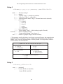
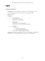
^HY – Upload Graphics .............................................................................................155
^HZA – Display All Description Information ...........................................................156
^HZF – Format Parameter Setting Information .........................................................157
^HZL – Object Directory Listing Information...........................................................158
^HZO – Individual Object Data Information .............................................................159
^HZR – Status Information ........................................................................................160
^ID – Object Delete....................................................................................................161
^IL – Image Load .......................................................................................................163
^IM – Image Move.....................................................................................................165
^IS – Image Save........................................................................................................166
~JA – Cancel All ........................................................................................................168
^JB – Initialize Flash Memory ...................................................................................169
ZPL II Programming Guide Volume One: Command Reference for X.10
ZPL II Programming Guide Volume One: Command Reference for X.10
~JB – Reset Optional Memory...................................................................................170
^JC – Set Media Sensor Calibration...........................................................................171
~JD – Enable Communications Diagnostics ..............................................................171
~JE – Disable Diagnostics..........................................................................................171
~JF – Set Battery Condition .......................................................................................172
~JG – Graphing Sensor Calibration ...........................................................................173
^JJ – Set Auxiliary Port..............................................................................................174
~JL – Set Label Length ..............................................................................................176
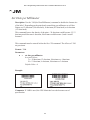
^JM – Set Dots per Millimeter ...................................................................................177
~JN – Head Test Fatal ................................................................................................178
~JO – Head Test Non-fatal.........................................................................................178
~JP – Pause and Cancel Format .................................................................................179
~JR– Power On Reset.................................................................................................180
~JS – Change Backfeed Sequence .............................................................................181
^JT – Head Test Interval ............................................................................................183
^JU – Configuration Update.......................................................................................184
^JW – Set Ribbon Tension .........................................................................................184
~JX – Cancel Current Partially Input Format ............................................................185
^JZ – Reprint After Error ...........................................................................................185
~KB – Kill Battery (Battery Discharge Mode) ..........................................................186
^KD – Date/Time Format (for Real Time Clock) ......................................................187
^KL – Define Language .............................................................................................188
^KN – Define Printer Name .......................................................................................189
^KP – Define Password..............................................................................................190
^LH – Label Home.....................................................................................................191
^LL – Label Length....................................................................................................192
^LR – Label Reverse Print .........................................................................................193
^LS – Label Shift .......................................................................................................194
^LT – Label Top.........................................................................................................195
^MC – Map Clear.......................................................................................................196
ZPL II Programming Guide Volume One: Command Reference for X.10
ZPL II Programming Guide Volume One: Command Reference for X.10
^MD – Media Darkness .............................................................................................197
^MF – Media Feed .....................................................................................................198
^ML – Maximum Label Length .................................................................................199
^MM – Print Mode.....................................................................................................200
^MN – Media Tracking ..............................................................................................202
^MP – Mode Protection .............................................................................................203
^MT – Media Type.....................................................................................................204
^MU – Set Units of Measurement..............................................................................205
~NC – Network Connect............................................................................................207
^NI – Network ID Number ........................................................................................208
~NR – Set All Network Printers Transparent ............................................................208
~NT – Set Currently Connected Printer Transparent.................................................209
^PF – Slew Given Number of Dot Rows ...................................................................210
^PH ~PH – Slew to Home Position...........................................................................211
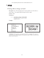
^PM – Printing Mirror Image of Label ......................................................................212
^PO – Print Orientation ..............................................................................................213
^PP ~PP – Programmable Pause ...............................................................................215
^PQ – Print Quantity ..................................................................................................216
^PR – Print Rate .........................................................................................................217
~PR – Applicator Reprint...........................................................................................219
~PS – Print Start .........................................................................................................219
^PW – Print Width .....................................................................................................220
~RO – Reset Advanced Counter ................................................................................220
^SC – Set Communications........................................................................................221
~SD – Set Darkness....................................................................................................222
^SE – Select Encoding ...............................................................................................222
^SF – Serialization Field (with a Standard ^FD String).............................................223
^SL – Set Mode/Language (for Real Time Clock) ....................................................225
^SN – Serialization Data ............................................................................................226
^SO – Set Offset (for Real Time Clock) ....................................................................229
^SP – Start Print .........................................................................................................230
^SQ – Halt ZebraNet ALERT ....................................................................................232
^SR – Set Printhead Resistance..................................................................................233
ZPL II Programming Guide Volume One: Command Reference for X.10
ZPL II Programming Guide Volume One: Command Reference for X.10
^SS – Set Media Sensors............................................................................................234
^ST – Set Time/Date (for Real Time Clock) .............................................................236
^SX – Set ZebraNet ALERT......................................................................................238
^SZ – Set ZPL ............................................................................................................240
~TA – Tear-off Adjust Position .................................................................................241
^TO – Transfer Object ...............................................................................................242
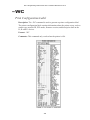
~WC – Print Configuration Label ..............................................................................245
^WD – Print Directory Label .....................................................................................246
^XA – Start Format ....................................................................................................248
^XB – Suppress Backfeed ..........................................................................................249
^XF – Recall Format ..................................................................................................250
^XG – Recall Graphic ................................................................................................251
^XZ – End Format......................................................................................................252
^ZZ – Printer Sleep ....................................................................................................252
ZPL II Programming Guide Volume One: Command Reference for X.10
INTRODUCTION
Volume One
Welcome to ZPL II Programming for X.10 Firmware
ZPL II Programming Guide Volume One: Command Reference for X.10 is designed
for users who already have an understanding of how to create labels and formats
using the Zebra Programming Language (ZPL II). Volume One is the unabridged,
alphabetical reference of programming commands supported in the X.10 release of
Zebra Printer firmware.
Note: This reference is designed somewhat differently than previous releases of the
ZPL II Programming Guide. Volume One is specific for programming Zebra
Printers using only the X.10 release of Zebra Printer firmware. The printer’s
firmware version can be determined by printing out a configuration label. Firmware
upgrade information is also available at http://www.zebra.com.
If you are using a previous version of Zebra Printer firmware, you will find that
some of the commands are the same and function as they have in the past – but
equally as many are new and will not be recognized by firmware that is earlier than
X.10. Other commands have been redesigned and significantly enhanced to support
more powerful innovations like ZebraNet ALERT, and the Real Time Clock.
While many of the commands in this text have examples included to assist with
proper ZPL II usage, these example are not designed to be a complete training
reference. Users who are unfamiliar with ZPL II programming should refer to the
ZPL II Programming Guide Volume Two: The X.10 Environment for information on
how to get started with the language.
To provide more information and convenient cross-referencing, commands that are
directly related to features discussed in Volume Two have been noted under their
Comments heading, pointing to the appendix or section that applies.
If you are an experienced user of the ZPL II programming language, you may wish
to browse this volume to reacquaint yourself with some of the commands and look
for additions to those you already use.
For those unfamiliar with ZPL II, look through this volume and take note of some of
the commands and the scope of what the language can do. Using these two volumes
together will quickly bring you up to speed and have you creating dynamic labels in
no time.
1
ZPL II Programming Guide Volume One: Command Reference for X.10
2
ZPL II Programming Guide Volume One: Command Reference for X.10
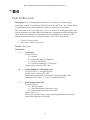
SECTION ONE
ZPL II Programming Commands
Using Section One: ZPL II Command Reference
This section contains the complete alphabetical listing of ZPL II commands
supported by the X.10 firmware release.
The text in Section One is arranged using the following headings and conventions:
Description: Under this heading you will find an explanation of how the command
is used, what it is capable of, and any defining characteristics it may have.
Format: Format explains how the command is syntactically arranged and what
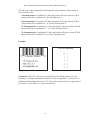
parameters it contains. For example, examine the ^B8 command, which prints a
EAN-8 bar code.
The format of this command is ^B8o,h,f,g. It is arranged with the caret symbol (^),
the command code (B8), and the parameters (o,h,f, and g). Each of the letters that
follow ^B8 – o,h,f, and g – are parameters and are replaced with supported values
determined by the user.
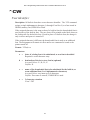
Parameters: If a command has values that the user can define to make its function
more specific, these are outlined as parameters. Parameters typically have Accepted
Values and Default Values.
Still using the ^B8 example, the h parameter is defined as:
h =
bar code height in dots
Accepted Values: 1 to 32000 (dots)
Default Value: Value set by ^BY
If the command has no parameters – for example ~JA (cancel all) – the parameter
heading is removed, indicating that the format of the command (~JA) is acceptable
ZPL II code.
3
ZPL II Programming Guide Volume One: Command Reference for X.10
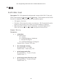
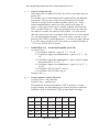
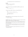
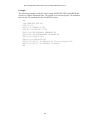
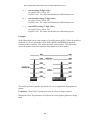
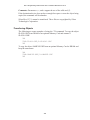
Example: When the command is best clarified in context, an example of the ZPL II
code is provided. Text indicating exact code entered by the user is printed in an
easily recognizable Courier font. An example of code using the ^B8 command
would look like this:
^XA
^FO50,50
^B8N,100,Y,N
^FD1234567^FS
^XZ
Notice that the ^B8 parameter letters have been replaced with real values that apply
to the command. In this example, N, 100, Y, N have been entered.
Comments: This section is reserved for notes that are of value to a programmer,
warnings of potential command interactions, or command-specific information that
should be taken into consideration. An example comment could be: This command
only works when the printer is idle or This command is ignored if a value exceeds the
parameter limits.
Comments are also included next to parameters if they are directly applicable to a
particular setting.
A complete listing of ZPL II commands for the X.10 firmware begins on page 6.
4
ZPL II Programming Guide Volume One: Command Reference for X.10
^A
Scalable/Bitmapped Font
Description: The ^A command is used with build-in or TrueType® fonts. ^A
designates the font for the current ^FD statement or field. The font specified in ^A
will be used only once for that ^FD entry. If ^A is not specified again, the default
^CF font will be used for the next ^FD entry.
Format: ^Af,o,h,w
Parameters:
f =
font name
Accepted Values: letters A through Z, and numbers 1 to 9.
Default Value: A
Any font in the printer (downloaded, EPROM, stored fonts, font A
through Z and 1 to 9) can also be selected with the ^CW command. If
the value is incorrect or unspecified, it will revert to the default or the
current ^CF value.
o =
font orientation
Accepted Values:
N = normal
R = rotated 90 degrees (clockwise)
I = inverted 180 degrees
B = read from bottom up, 270 degrees
Default Value: the last accepted ^FW value or the ^FW default.
h =
character height (in dots)
Scalable:
Accepted Values: 10 to 32000
Default Value: 15, or the last accepted value for ^CF.
Bitmapped:
Accepted Values: Multiples of height from 2 to 10 times the
standard height, in increments of 1.
Default Value: The standard matrix height for a specified font.
w =
width (in dots)
Scalable:
Accepted Values: 10 to 32000
Default Value: 12, or last accepted value for ^CF.
Bitmapped:
Accepted Values: Multiples of width from 2 to 10 times the
standard width, in increments of 1.
Default Value: The standard matrix width for a specified font.
5
ZPL II Programming Guide Volume One: Command Reference for X.10
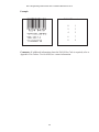
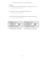
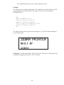
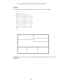
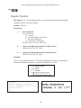
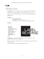
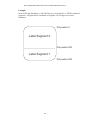
Example:
Scalable Font Command
^XA
^FO50,50^A0,32,25^FDZEBRA^FS
^FO50,150^A0,32,25^FDPROGRAMMING^FS
^FO50,250^A0,32,25^FDLANGUAGE II^FS
^XZ
Bitmap Font Command
^XA
^FO50,50^ADN,36,20^FDZEBRA^FS
^FO50,100^ADN,36,20^FDPROGRAMMING^FS
^FO50,150^ADN,36,20^FDLANGUAGE II^FS
^XZ
Comments: Fonts are built using a matrix that defines standard height-to-width
ratios. If you specify only the height or width value, the standard matrix for that font
will automatically determine the other value. If the value is blank or a 0 (zero) is
entered, the height or width will be determined by the standard font matrix.
For more information on scalable and bitmap fonts, refer to Appendix E or the
section “Differences Between Download Scalable and Bitmap Fonts” in Volume
Two.
6
ZPL II Programming Guide Volume One: Command Reference for X.10
^A@
Use Font Name to Call Font
Description: The ^A@ command uses the complete name of a font, rather than the
character designation used in ^A. Once ^A@ is defined, it will represent that font
until a new font name is specified by ^A@.
Format: ^A@o,h,w,n
Parameters:
o =
font orientation
Accepted Values:
N = normal
R = rotated 90 degrees (clockwise)
I = inverted 180 degrees
B = read from bottom up, 270 degrees
Default Value: Last ^FW value or N if an orientation is not specified.
h =
character height (in dots)
Default Value: Magnification specified by w (character width) or the
last accepted ^CF value. The base height is used if none is specified.
Scalable: The value is the height in dots of the entire character
block. Magnification factors are unnecessary, since characters
are scaled.
Bitmapped: The value is rounded to nearest integer multiple of the
font’s base height, then divided by the font’s base height to
give a magnification nearest limit.
w =
character width (in dots)
Default Value: Magnification specified by h (height) or the last
accepted ^CF value. The base width is used if none is specified.
Scalable: The value is the width in dots of the entire character
block. Magnification factors are unnecessary, since characters
are scaled.
Bitmapped: The value is rounded to nearest integer multiple of the
font’s base width, then divided by the font’s base width to
give a magnification nearest limit.
n =
font name (.FNT extension)
Accepted Values: any valid font (with the extension .FNT)
Default Value: If no letter designates the device location, the default
device is RAM or R:. The font named will carry over on all subsequent
^A@ commands without a font name.
7
ZPL II Programming Guide Volume One: Command Reference for X.10
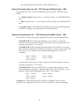
Example:
^XA^A@N,25,25,B:Cyrillic.FNT^FO100,20^FS
^FDThis is a test^FS
^A@N,50,50^FO200,40^FS
^FDThis string uses the B:Cyrillic.FNT^FS^XZ
The first line will search the non-volatile memory of the printer (e.g. B:) looking for
the “Cyrillic.FNT” font name. When the font is found, the command will set the
character size, the field origin, and print the field data “This is a test” on a label (line
2).
In the third command line, the character size is increased and a new field origin is
set. Line 4 prints the field data “This string uses the B:Cyrillic.FNT” in the same
font.
Comments: For more information on scalable and bitmap fonts, refer to Appendix
E or the section “Differences Between Download Scalable and Bitmap Fonts” in
Volume Two.
8
ZPL II Programming Guide Volume One: Command Reference for X.10
^B1
Code 11 Bar Code
Description: The ^B1 command is also known as USD-8 code. In a Code 11 bar
code, each character is composed of three bars and two spaces, and the character set
includes 10 digits plus a dash.
•
•
^B1 supports print ratios of 2.0:1 to 3.0:1.
Field data (^FD) is limited to the width (or length, if rotated) of the label.
Format: ^B1o,e,h,f,g
Parameters:
o =
orientation
Accepted Values:
N = normal
R = rotated 90 degrees (clockwise)
I = inverted 180 degrees
B = read from bottom up, 270 degrees
Default Value: Current ^FW value
e =
check digit
Accepted Values:
Y (yes) = 1 digit
N (no) = 2 digits
Default Value: N
h =
bar code height (in dots)
Accepted Values: 1 to 32000
Default Value: Value set by ^BY
f =
print interpretation line
Accepted Values: Y (yes) or N (no)
Default Value: Y
g =
print interpretation line above code
Accepted Values: Y(yes) or N (no)
Default Value: N
9
ZPL II Programming Guide Volume One: Command Reference for X.10
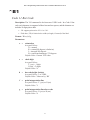
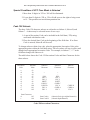
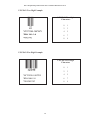
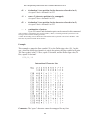
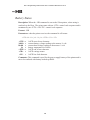
Example:
Characters
0
1
2
3
4
5
6
7
8
9
Internal Start/Stop Characters
@
When used as a stop character
@ is used with 1 check digit
@ is used with 2 check digits
Comments: If additional information about the Code 11 Bar Code is required, refer
to Appendix H in Volume Two for AIM, Inc. contact information.
10
ZPL II Programming Guide Volume One: Command Reference for X.10
^B2
Interleaved 2 of 5 Bar Code
Description: The ^B2 command is a high density, self-checking, continuous,
numeric symbology.
Each data character for the Interleaved 2 of 5 Bar Code is composed of five
elements: five bars or five spaces. Of the five elements, two are wide and three are
narrow. The bar code is formed by interleaving characters formed with all spaces
into characters formed with all bars.
•
•
^B2 supports print ratios of 2.0:1 to 3.0:1.
Field data (^FD) is limited to the width (or length, if rotated) of the label.
Format: ^B2o,h,f,g,e
Parameters:
o =
orientation
Accepted Values:
N = normal
R = rotated 90 degrees (clockwise)
I = inverted 180 degrees
B = read from bottom up, 270 degrees
Default Value: Current ^FW value
h =
bar code height (in dots)
Accepted Values: 1 to 32000
Default Value: Value set by ^BY
f =
print interpretation line
Accepted Values: Y (yes) or N (no)
Default Value: Y
g =
print interpretation line above code
Accepted Values: Y (yes) or N (no)
Default Value: N
e =
calculate and print Mod 10 check digit
Accepted Values: Y (yes) or N (no)
Default Value: N
11
ZPL II Programming Guide Volume One: Command Reference for X.10
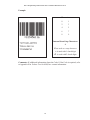
Example:
Interleaved 2 of 5
Characters
0
1
2
3
4
5
6
7
8
9
Start Stop (internal)
Comments: The total number of digits in an Interleaved Bar Code must be even.
The printer automatically adds a leading 0 (zero) if an odd number of digits is
received.
The Interleaved 2 of 5 bar code uses the Mod 10 check-digit scheme for error
checking. For more information on Mod 10 check digits, refer to Appendix C in
Volume Two.
If additional information about the Interleaved 2 of 5 bar code is required, refer to
Appendix H in Volume Two for AIM, Inc. contact information.
12
ZPL II Programming Guide Volume One: Command Reference for X.10
^B3
Code 39 Bar Code
Description: The Code 39 bar code is the standard for many industries, including the
U.S. Department of Defense (DOD). It is one of three symbologies identified in the
American National Standards Institute (ANSI) standard MH10.8M-1983. Code 39 is
also known as “USD-3 Code” and “3 of 9 Code.”
Each character in a Code 39 bar code is composed of nine elements: five bars, four
spaces, and an inter-character gap. Three of the nine elements are wide; the six
remaining elements are narrow.
•
•
•
•
^B3 supports print ratios of 2.0:1 to 3.0:1.
Field data (^FD) is limited to the width (or length, if rotated) of the label.
Code 39 automatically generates the Start and Stop Character (*)
Code 39 is capable of encoding the full 128-character ASCII set.
Format: ^B3o,e,h,f,g
Parameters:
o =
orientation
Accepted Values:
N = normal
R = rotated 90 degrees (clockwise)
I = inverted 180 degrees
B = read from bottom up, 270 degrees
Default Value: Current ^FW value
e =
Mod-43 check digit
Accepted Values: Y (yes) or N (no)
Default Value: N
h =
bar code height (in dots)
Accepted Values: 1 to 32000
Default Value: Value set by ^BY
f =
print interpretation line
Accepted Values: Y (yes) or N (no)
Default Value: Y
g =
print interpretation line above code
Accepted Values: Y (yes) or N (no)
Default Value: N
13
ZPL II Programming Guide Volume One: Command Reference for X.10
Example:
Code 39 Characters
Code 39 Bar Code
1
A
K
U
-
2
B
L
V
.
3
C
M W $
4
D
N
X
/
5
E
O
Y
+
6
F
P
Z
%
7
G
Q
8
H
R
9
I
S
0
J
T
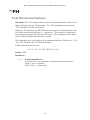
Comments: Extended ASCII is a function of the scanner, not of the bar code. Your
scanner must have Extended ASCII enabled in order for this feature to work. To
turn on (enable) Extended ASCII in the Code 39, you must first encode “+$” in your
^FD statement. To disable Extended ASCII, you must encode “-$” in your ^FD
statement.
For example, to encode a carriage return with line feed into a Code 39 bar code:
^XA^FO20,20^B3N^FDTEST+$$M$J-$^FS^XZ
If additional information about the Code 39 Bar Code is required, refer to Appendix
H in Volume Two for AIM, Inc. contact information.
14
ZPL II Programming Guide Volume One: Command Reference for X.10
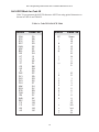
Full ASCII Mode for Code 39
Code 39 can generate the full 128-character ASCII set using paired characters as
shown in Table A and Table B.
Table A: Code 39 Full ASCII Mode
ASCII
SOH
STX
ETX
EOT
ENQ
ACK
BEL
BS
HT
LF
VT
FF
CR
SO
SI
DLE
DC1
DC2
DC3
DC4
NAK
SYN
ETB
CAN
EM
SUB
ESC
FS
FS
RS
US
ASCII
Code 39
SP
!
“
#
$
%
&
‘
(
)
*
++
‘
.
/
0
1
2
3
4
5
6
7
8
9
:
;
<
=
>
?
$A
$B
$C
$D
$E
$F
$G
$H
$I
$J
$K
$L
$M
$N
$O
$P
$Q
$R
$S
$T
$U
$V
$W
$X
$Y
$Z
%A
%B
%C
%D
%E
15
Code 39
Space
/A
/B
/C
/D
/E
/F
/G
/H
/I
/J
/K
/L
.
/O
O
1
2
3
4
5
6
7
8
9
/Z
%F
%G
%H
%I
%J
ZPL II Programming Guide Volume One: Command Reference for X.10
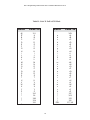
Table B: Code 39 Full ASCII Mode
ASCII
Code 39
ASCII
Code 39
@
A
B
C
D
E
F
G
H
I
J
K
L
M
N
O
P
Q
R
S
T
U
V
W
X
Y
Z
[
\
]
^
_
%V
A
B
C
D
E
F
G
H
I
J
K
L
M
N
O
P
Q
R
S
T
U
V
W
X
Y
Z
%K
%L
%M
%N
%O
‘
a
b
c
d
e
f
g
h
I
j
k
l
m
n
o
p
q
r
s
t
u
v
w
x
y
z
{
|
}
~
DEL
%W
+A
+B
+C
+D
+E
+F
+G
+H
+I
+J
+K
+L
+M
+N
+O
+P
+Q
+R
+S
+T
+U
+V
+W
+X
+Y
+Z
%P
%Q
%R
%S
%T, %X
16
ZPL II Programming Guide Volume One: Command Reference for X.10
^B4
Code 49 Bar Code
Description: The ^B4 command is a multi-row, continuous, variable-length
symbology capable of encoding the full 128-character ASCII set. It is ideally suited
for applications where large amounts of data are required in a small space.
The code consists of two to eight rows. A row consists of a leading quiet zone, four
symbol characters encoding eight code characters, a stop pattern, and a trailing quiet
zone. Rows are separated by a separator bar with a height of one module. Each
symbol character encodes two characters from a set of 49 code characters.
•
•
^B4 has a fixed print ratio.
Rows can be scanned in any order.
Format: ^B4o,h,f,m
Parameters:
o =
orientation
Accepted Values:
N = normal
R = rotated 90 degrees (clockwise)
I = inverted 180 degrees
B = read from bottom up, 270 degrees
Default Value: Current ^FW value
h =
height multiplier of individual rows
Accepted Values: 1 to height of label
Default Value: Value set by ^BY
This number multiplied by the module equals the height of the
individual rows in dots. 1 is not a recommended value.
f =
print interpretation line
Accepted Values:
N = No line printed
A = Print interpretation line above code
B = Print interpretation line below code
Default Value: N
When code exceeds 2 rows, expect the interpretation line to extend
beyond the right edge of the code.
17
ZPL II Programming Guide Volume One: Command Reference for X.10
m =
starting mode
Accepted Values:
0 = Regular Alphanumeric Mode
1 = Multiple Read Alphanumeric
2 = Regular Numeric Mode
3 = Group Alphanumeric Mode
4 = Regular Alphanumeric Shift 1
5 = Regular Alphanumeric Shift 2
A = Automatic mode. The printer determines starting mode by
analyzing field data.
Default Value: A
Example:
Comments: If additional information about the Code 49 Bar Code is required, refer
to Appendix H in Volume Two for AIM, Inc. contact information.
18
ZPL II Programming Guide Volume One: Command Reference for X.10
Field Data
Set
Unshifted
Character Set
Shift 1
Character Set
Shift 2
Character Set
0
1
2
3
4
5
6
7
8
9
A
B
C
D
E
F
G
H
I
J
K
L
M
N
O
P
Q
R
S
T
U
V
W
X
Y
Z
.
SPACE
$
/
++
%
< (Shift 1)
> (Shift 2)
: (N.A.)
; (N.A.)
? (N.A.)
= (Numeric Shift)
0
1
2
3
4
5
6
7
8
9
A
B
C
D
E
F
G
H
I
J
K
L
M
N
O
P
Q
R
S
T
U
V
W
X
Y
Z
.
SPACE
$
/
++
%
’
ESC
FS
GS
RS
US
!
“
#
&
SOH
STX
ETX
EOT
ENQ
ACK
BEL
BS
HT
LF
VT
FF
CR
SO
SI
DLE
DC1
DC2
DC3
DC4
NAK
SYN
ETB
CAN
EM
SUB
(
)
Null
*
,
:
reserved
;
<
=
>
?
@
[
\
]
a
b
c
d
e
f
g
h
I
j
k
l
m
n
o
p
q
r
s
t
u
v
w
x
y
z
_
‘
DEL
{
|
}
~
Code 49 Shift 1 and 2 Character Substitutions
19
ZPL II Programming Guide Volume One: Command Reference for X.10
Code 49 Field Data Character Set
The ^FD data sent to the printer when using starting modes 0 to 5 is based on the
Code 49 Internal Character Set. This is shown in the first column of the Code 49
table on the previous page. The characters
: ; < = > ?
are special Code 49 control characters.
Valid field data must be supplied when using modes 0 to 5. Shifted characters are
sent as a two-character sequence of a shift character followed by a character in the
unshifted character set.
For example, to encode a lowercase “a,” send a “Shift 2 (>)” followed by an
uppercase “A.” If interpretation line printing is selected, a lowercase “a” will print
in the interpretation line. This will reflect what the output from the scanner will
read. Code 49 uses uppercase alphanumeric characters only.
If an invalid sequence is detected, the Code 49 formatter will stop interpreting field
data and print a symbol with the data up to the invalid sequence. The following are
examples of invalid sequences:
•
•
•
•
•
•
Terminating numeric mode with any characters other than 0 through 9 or a Numeric
Space.
Starting in Mode 4 (Regular Alphanumeric Shift 1) and the first field data character is
not in the Shift 1 set.
Starting in Mode 5 (Regular Alphanumeric Shift 2) and the first field data character is
not in the Shift 2 set.
Sending Shift 1 followed by a character not in the Shift 1 set.
Sending Shift 2 followed by a character not in the Shift 2 set.
Sending two Shift 1 or Shift 2 control characters.
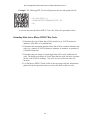
Advantages of Using the Code 49 Automatic Mode
Using the default (automatic mode) completely eliminates the need for selecting the
starting mode or manually performing character shifts. The automatic mode
analyzes the incoming ASCII string, determines the proper mode, performs all
character shifts, and compacts the data for maximum efficiency.
Numeric mode will only be selected or shifted when five or more continuous digits
are found. Numeric packaging provides no space advantage for numeric strings
consisting of fewer than eight characters.
20
ZPL II Programming Guide Volume One: Command Reference for X.10
^B7
PDF417 Bar Code
Description: The ^B7 command is a two-dimensional, multi-row, continuous
stacked symbology. PDF417 is capable of encoding over 1,000 characters per bar
code. It is ideally suited for applications where large amounts of information are
required at the time the bar code is read.
The code consists of 3 to 90 stacked rows. Each row consists of start and stop
patterns and symbol characters called “code-words.” A “code-word” consists of four
bars and four spaces. A three code-word minimum is required per row.
•
PDF417 has a fixed print ratio.
Format: ^B7o,h,s,c,r,t
Parameters:
o =
orientation
Accepted Values:
N = normal
R = rotated 90 degrees (clockwise)
I = inverted 180 degrees
B = read from bottom up, 270 degrees
Default Value: Current ^FW value
h =
bar code height for individual rows
Accepted Values: 1 to height of label
Default Value: Value set by ^BY
This number multiplied by the module equals the height of the
individual rows in dots. 1 is not a recommended value.
s =
security level
Accepted Values: 1 to 8 (error detection and correction)
Default value: 0 (error detection only)
This determines the number of error detection and correction codewords to be generated for the symbol. The default level provides only
error detection without correction. Increasing the security level adds
increasing levels of error correction and increases the symbol size.
c =
number of data columns to encode
Accepted Values: 1 to 30
Default Value: 1:2 (row-to-column aspect ratio)
The user can specify number of code-word columns given control over
the width of the symbol.
21
ZPL II Programming Guide Volume One: Command Reference for X.10
r =
number of rows to encode
Accepted Values: 3 to 90
Default value: 1:2 row-to-column aspect ratio.
The user can specify the number of symbol rows giving control over
the height of the symbol.
For example, with no row or column values entered, 72 code-words
would be encoded into a symbol of 6 columns and 12 rows. Depending
on code-words, the aspect ratio will not always be exact.
t =
truncate right row indicators and stop pattern
Accepted Values: Y (perform truncation) and N (no truncation).
Default Value: N
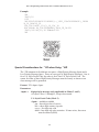
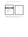
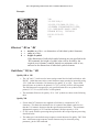
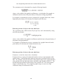
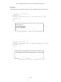
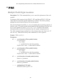
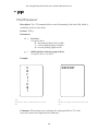
Example 1:
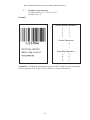
The following code will generate the symbol shown below left. The text used in the
^FD statement is listed to the right of the bar code.
^XA^BY2,3
^FO10,10^B7N,5,5,,83,N
^FD[Text shown at right of bar code]^FS
^XZ
22
ZPL II Programming Guide Volume One: Command Reference for X.10
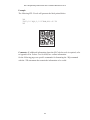
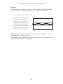
Example 2:
Comments:
•
•
•
•
•
If both columns and rows are specified, their product must be less than 928.
No symbol is printed if the product of columns and rows is greater than 928.
No symbol is printed if total code-words is greater than the product of columns and
rows.
Serialization is not allowed with this bar code.
The truncation feature can be used in situations where label damage is not likely. The
right row indicators and stop pattern will be reduced to a single module bar width.
The difference between a non-truncated and a truncated bar code is shown in Example
2.
23
ZPL II Programming Guide Volume One: Command Reference for X.10
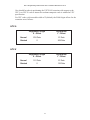
Special Considerations for ^BY When Using PDF417
When used with ^B7, the parameters for the ^BYw,r,t command are:
w =
r =
h =
module width. Default = 2. Limited to 10.
ratio. Default = 3. Ratio is fixed and does not effect PDF417.
height of bars (overall symbol height). PDF417 uses this only when
row height is not specified in the ^B7 h parameter.
Special Considerations for ^FD When Using PDF417
The character set sent to the printer includes the full ASCII set except for those
characters with special meaning to the printer.
CR/LF have become valid characters for all ^FD statements. The following scheme
will be used:
\& = carriage return/line feed
\(*) = soft hyphen (word break with a dash)
\\ = backslash (\)
(*) = Any alphanumeric character
•
•
^CI13 must be selected in order to print a backslash (\).
If a soft hyphen is placed near the end of a line, the hyphen will be printed. If it is not
placed near the end of the line, it will be ignored. This is ignored in the ^B7 bar code.
24
ZPL II Programming Guide Volume One: Command Reference for X.10
^B8
EAN-8 Bar Code
Description: The ^B8 command is the shortened version of the EAN-13 bar code.
EAN is an acronym for European Article Numbering. Each character in the EAN-8
bar code is composed of four elements: two bars and two spaces.
•
•
•
^B8 supports a fixed ratio.
Field data (^FD) is limited to exactly seven characters. ZPL II automatically pads or
truncates on the left with zeros to achieve the required number of characters.
When using JAN-8 (Japanese Article Numbering), a specialized application of
EAN-8, the first two non-zero digits sent to the printer will always be 49.
Format: ^B8o,h,f,g
Parameters:
o =
orientation
Accepted Values:
N = normal
R = rotated 90 degrees (clockwise)
I = inverted 180 degrees
B = read from bottom up, 270 degrees
Default Value: Current ^FW value
h =
bar code height (in dots)
Accepted Values: 1 to 32000
Default Value: Value set by ^BY
f =
print interpretation line
Accepted Values: Y (yes) or N (no)
Default Value: Y
g =
print interpretation line above code
Accepted Values: Y (yes) or N (no)
Default Value: N
25
ZPL II Programming Guide Volume One: Command Reference for X.10
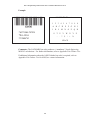
Example:
EAN-8 Characters
0
1
2
3
4
5
6
7
8
9
Comments: If additional information about the EAN-8 Bar Code is required, refer to
Appendix H in Volume Two for AIM, Inc. contact information.
26
ZPL II Programming Guide Volume One: Command Reference for X.10
^B9
UPC-E Bar Code
Description: The ^B9 command is a variation of the UPC symbology used for
number system 0. It is a shortened version of the UPC-A bar code in which zeros are
suppressed, resulting in codes that require less printing space. The 6 dot/mm, 12
dot/mm, and 24 dot/mm printheads produce the UPC/EAN symbologies at 100
percent of the size. However, an 8 dot/mm printhead will produce the UPC/EAN
symbologies at a magnification factor of 77 percent.
Each character in a UPC-E bar code is composed of four elements: two bars and two
spaces. The ^BY command must be used to specify the width of the narrow bar.
•
•
•
^B9 supports a fixed ratio.
Field data (^FD) is limited to exactly 10 characters, requiring a five-digit
manufacturer’s code and five-digit product code.
When using the zero-suppressed versions of UPC, the user must enter the full
10-character sequence. ZPL II will calculate and print the shortened version.
Format: ^Bo,h,f,g,e
Parameters:
o =
orientation
Accepted Values:
N = normal
R = rotated 90 degrees (clockwise)
I = inverted 180 degrees
B = read from bottom up, 270 degrees
Default Value: Current ^FW value
h =
bar code height (in dots)
Accepted Values: 1 to 32000
Default Value: Value set by ^BY
f =
print interpretation line
Accepted Values: Y (yes) or N (no)
Default Value: Y
g =
print interpretation line above code
Accepted Values: Y (yes) or N (no)
Default Value: N
e =
print check digit
Accepted Values: Y (yes) or N (no)
Default Value: Y
27
ZPL II Programming Guide Volume One: Command Reference for X.10
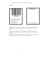
Example:
UPC-E Characters
0
1
2
3
4
5
6
7
8
9
Four Rules for Proper Product Numbers
1. If the last three digits in the manufacturer’s number are 000, 100, or 200,
valid Product Code numbers are 00000 to 00999.
2. If the last three digits in the manufacturer’s number are 300, 400 , 500, 600,
700, 800, or 900, valid Product Code numbers are 00000 to 00099.
3. If the last two digits in the manufacturer’s number are 10, 20, 30, 40 , 50, 60,
70, 80, or 90, valid Product Code numbers are 00000 to 00009.
4. If the manufacturer’s number does not end in zero (0), valid Product Code
numbers are 00005 to 00009.
Comments: If additional information about the UPC-E Bar Code is required, refer to
Appendix H in Volume Two for AIM, Inc. contact information.
28
ZPL II Programming Guide Volume One: Command Reference for X.10
^BA
Code 93 Bar Code
Description: The ^BA command is a variable length, continuous symbology. It is
used in many of the same applications as Code 39. It uses the full 128-character
ASCII Code. ZPL II, however, does not support ASCII control codes or escape
sequences. It uses the substitute characters shown below.
Control Code
ZPL II Substitute
Ctrl $
Ctrl %
Ctrl /
Ctrl +
&
‘
(
)
Each character in Code 93 Bar Code is composed of six elements: three bars and
three spaces. Although invoked differently, the human-readable interpretation line
will print as though the control code has been used.
•
•
^BA supports a fixed print ratio.
Field data (^FD) is limited to the width (or length, if rotated) of the label.
Format: ^BAo,h,f,g,e
Parameters:
o
=
orientation
Accepted Values:
N = normal
R = rotated 90 degrees (clockwise)
I = inverted 180 degrees
B = read from bottom up, 270 degrees
Default Value: Current ^FW value
h =
bar code height (in dots)
Accepted Values: 1 to 32000
Default Value: Value set by ^BY
f =
print interpretation line
Accepted Values: Y (yes) or N (no)
Default Value: Y
29
ZPL II Programming Guide Volume One: Command Reference for X.10
g =
print interpretation line above code
Accepted Values: Y (yes) or N (no)
Default Value: N
e =
print check digit
Accepted Values: Y (yes) or N (no)
Default Value: N
Example:
Code 93 Characters
1
2
3
4
5
6
7
8
9 0
A B C D E F G H I J K
L M N O P Q R S T U V
W X Y Z
-
.
$
/
+
%
&
’
( )
SPACE
Denotes an internal start/stop character
that must precede and follow every bar
code message.
Comments: All the control codes are used in pairs. For specific details, refer to the
Code 93 specification.
Code 93 is also capable of encoding the full 128-character ASCII Set. See Tables A
and B on the following pages.
If additional information about the Code 93 Bar Code is required, refer to Appendix
H in Volume Two for AIM, Inc. contact information.
30
ZPL II Programming Guide Volume One: Command Reference for X.10
Full ASCII Mode for Code 93
Code 93 can generate the full 128-character ASCII Set using paired characters as
shown in tables A and B.
Table A: Code 93 Full ASCII Mode
ASCII
NUL
SOH
STX
ETX
EOT
ENQ
ACK
BEL
BS
HT
LF
VT
FF
CR
SO
SI
DLE
DC1
DC2
DC3
DC4
NAK
SYN
ETB
CAN
EM
SUB
ESC
FS
FS
RS
US
Code 93
ASCII
‘U
&A
&B
&C
&D
&E
&F
&G
&H
&I
&J
&K
&L
&M
&N
&O
&P
&Q
&R
&S
&T
&U
&V
&W
&X
&Y
&Z
‘A
‘B
‘C
‘D
‘E
SP
!
“
#
$
%
&
‘
(
)
*
++
‘
.
/
0
1
2
3
4
5
6
7
8
9
:
;
<
=
>
?
31
Code 93
Space
(A
(B
(C
(D
(E
(F
(G
(H
(I
(J
++
(L
.
/
O
1
2
3
4
5
6
7
8
9
(Z
‘F
‘G
‘H
‘I
‘J
ZPL II Programming Guide Volume One: Command Reference for X.10
Table B: Code 93 Full ASCII Mode
ASCII
Code 93
ASCII
Code 93
@
A
B
C
D
E
F
G
H
I
J
K
L
M
N
O
P
Q
R
S
T
U
V
W
X
Y
Z
[
\
]
^
_
‘V
A
B
C
D
E
F
G
H
I
J
K
L
M
N
O
P
Q
R
S
T
U
V
W
X
Y
Z
‘K
‘L
‘M
‘N
‘O
‘
a
b
c
d
e
f
g
h
I
j
k
l
m
n
o
p
q
r
s
t
u
v
w
x
y
z
{
|
}
~
DEL
‘W
)A
)B
)C
)D
)E
)F
)G
)H
)I
)J
)K
)L
)M
)N
)O
)P
)Q
)R
)S
)T
)U
)V
)W
)X
)Y
)Z
‘P
‘Q
‘R
‘S
‘T
32
ZPL II Programming Guide Volume One: Command Reference for X.10
^BB
CODABLOCK Bar Code
Description: The ^BB command is a two-dimensional multi-row, stacked
symbology. It is ideally suited for applications that require large amounts of
information.
Depending on the mode selected, the code consists of 1 to 44 stacked rows. Each
row begins and ends with a start/stop pattern.
•
•
CODABLOCK A supports variable print ratios.
CODABLOCK E and F support only fixed print ratios.
Format:^BBo,h,s,c,r,m
Parameters:
o =
orientation
Accepted Values:
N = normal
R = rotated 90 degrees (clockwise)
I = inverted 180 degrees
B = read from bottom up, 270 degrees
Default Value: N
h =
bar code height for individual rows (in dots)
Accepted Values: 2 to 32000
Default Value: 8
This number, multiplied by the module, equals the height of the
individual row in dots.
s =
security level
Accepted Values: Y (yes) or N (no)
Default Value: Y
This determines if symbol check-sums will be generated and added to
the symbol. Check sums are never generated for single-row symbols.
This can only be turned off if parameter m is set to A.
c =
number of characters per row (data columns).
Accepted Values: 2 to 62 characters
This is used to encode a CODABLOCK Symbol. It gives the user
control over the width of the symbol.
33
ZPL II Programming Guide Volume One: Command Reference for X.10
r =
number of rows to encode
Accepted Values:
CODABLOCK A: 1 to 22
CODABLOCK E and F: 2 to 4
•
•
•
•
•
m =
If values for c and r are not specified, a single row will be produced.
If a value for r is not specified, and c exceeds the maximum range, a single
row equal to the field data length will be produced.
If a value for c is not specified, the number of characters per row is derived
by dividing the field data by the value of r.
If both parameters are specified, the amount of field data must be less than
the product of the specified parameters. If the field data exceeds the value
of the product, either no symbol or an error code is printed (if ^CV is
active).
If the data field contains primarily numeric data, fewer than the specified
rows may be printed. If the field data contains several shift and code switch
characters, more than the specified number of rows may be printed.
mode
Accepted Values: A, E, F
CODABLOCK A uses the Code 39 character set.
CODABLOCK F uses the Code 128 character set.
CODABLOCK E uses the Code 128 character set and
automatically adds FNC1.
Default Value: F
34
ZPL II Programming Guide Volume One: Command Reference for X.10
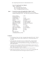
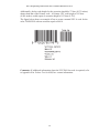
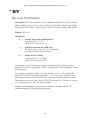
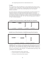
Example:
The code below prints the following CODABLOCK bar code.
^XA^LH10,10^FS
^BY2,3^FO50,50^BBN,30,,30,44,E
^FD Zebra Technologies Corporation strives to be the
expert supplier of innovative solutions to specialty
demand labeling and ticketing problems of business
and government. We will attract and retain the best
people who will understand our customer’s needs and
provide them with systems, hardware, software,
consumables, and service offering the best value,
high quality, and reliable performance, all delivered
in a timely manner.^FS
^XZ
35
ZPL II Programming Guide Volume One: Command Reference for X.10
Special Considerations for the ^BY Command When Using ^BB
The parameters for the ^BYw,r,h command, when used with a ^BB code, are as
follows:
w = Module width. Default Value: 2 Maximum Value: 10. (CODABLOCK A
only).
r = Ratio. Default Value: 3 (fixed value; this has no effect on CODABLOCK E
or F).
h = Height of bars. CODABLOCK uses this as the overall symbol height only
when the row height is not specified in the ^BB h parameter.
Special Considerations for ^FD Character Set When Using ^BB
The character set sent to the printer depends on the mode selected in parameter m.
CODABLOCK A: Uses the same character set as Code 39. If any other
character is used in the ^FD statement, either no bar code is printed or an error
message is printed (if ^CV is active).
CODABLOCK E: The automatic mode includes the full ASCII set except for
those characters with special meaning to the printer. Function codes or the Code
128 subset A <nul> character can be inserted through the use of the ^FH
command.
<fnc1> = 80 hex
<fnc2> = 81 hex
<nul>= 84 hex
<fnc3>= 82 hex
<fnc4>= 83 hex
For any other character above 84 hex, either no bar code is printed or an error
message is printed (if ^CV is active).
CODABLOCK F: Uses the full ASCII set except for those characters with
special meaning to the printer. Function codes or the Code 128 subset A <nul>
character can be inserted through the use of the ^FH command.
<fnc1> = 80 hex
<fnc2>= 81 hex
<nul>= 84 hex
<fnc3>= 82 hex
<fnc4>= 83 hex
Comments: If additional information about the CODABLOCK Bar Code is
required, refer to Appendix H in Volume Two for AIM, Inc. contact information.
36
ZPL II Programming Guide Volume One: Command Reference for X.10
^BC
Code 128 Bar Code (Subsets A, B, and C)
Description: The ^BC command is a high-density, variable length, continuous,
alphanumeric symbology. It was designed for complexly encoded product
identification.
Code 128 has three subsets of characters. There are 106 encoded printing characters
in each set, and each character can have up to three different meanings, depending on
the character subset being used. Each Code 128 character consists of six elements:
three bars and three spaces.
•
•
^BC supports a fixed print ratio.
Field data (^FD) is limited to the width (or length, if rotated) of the label.
Format: ^BCo,h,f,g,e,m
Parameters:
o =
orientation
Accepted Values:
N = normal
R = rotated 90 degrees (clockwise)
I = inverted 180 degrees
B = read from bottom up, 270 degrees
Default Value: Current ^FW value
h =
bar code height (in dots)
Accepted Values: 1 to 32000
Default Value: Value set by ^BY
f =
print interpretation line
Accepted Values: Y (yes) or N (no)
Default Value: Y
The interpretation line can be printed in any font by placing the font
command before the bar code command.
g =
print interpretation line above code
Accepted Values: Y (yes) or N (no)
Default Value: N
e =
UCC check digit
Accepted Values: Y (yes) or N (no)
Default Value: N
37
ZPL II Programming Guide Volume One: Command Reference for X.10
m =
mode
Accepted Values:
N – no selected mode
U – UCC Case Mode
A – Automatic Mode. This analyzes the data sent and
automatically determines the best packing method. The full
ASCII character set can be used in the ^FD statement. The
printer will determine when to shift subsets. A string of four
or more numeric digits will cause an automatic shift to subset
C.
Default Value: N
Example:
Comments: If additional information about the Code 128 bar code is required, refer
to Appendix H in Volume Two for AIM, Inc. contact information.
38
ZPL II Programming Guide Volume One: Command Reference for X.10
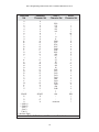
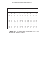
The following tables represent the Code 128 Character Sets.
Value
0
1
2
3
4
5
6
7
8
9
10
11
12
13
14
15
16
17
18
19
20
21
22
23
24
25
26
27
28
29
30
31
32
33
34
35
36
37
38
39
40
41
42
43
44
45
46
47
48
49
50
51
52
Code A
SP
!
''
#
$
%
&
'
(
)
*
++
,
.
/
0
1
2
3
4
5
6
7
8
9
:
;
<
=
>
?
@
A
B
C
D
E
F
G
H
I
J
K
L
M
N
O
P
Q
R
S
T
Code B
SP
!
''
#
$
%
&
'
(
)
*
++
,
.
/
0
1
2
3
4
5
6
7
8
9
:
;
<
=
>
?
@
A
B
C
D
E
F
G
H
I
J
K
L
M
N
O
P
Q
R
S
T
Code C
00
01
02
03
04
05
06
07
08
09
10
11
12
13
14
15
16
17
18
19
20
21
22
23
24
25
26
27
28
29
30
31
32
33
34
35
36
37
38
39
40
41
42
43
44
45
46
47
48
49
50
51
52
Value
53
54
55
56
57
58
59
60
61
62
63
64
65
66
67
68
69
70
71
72
73
74
75
76
77
78
79
80
81
82
83
84
85
86
87
88
89
90
91
92
93
94
95
96
97
98
99
100
101
102
103
104
105
39
Code A
U
V
W
X
Y
Z
[
\
]
^
_
NUL
SOH
STX
ETX
EOT
ENQ
ACK
BEL
BS
HT
LF
VT
FF
CR
SO
SI
DLE
DC1
DC2
DC3
DC4
NAK
SYN
ETB
CAN
EM
SUB
ESC
FS
GS
RS
US
FNC3
FNC2
SHIFT
Code C
Code B
FNC4
FNC1
Code B
U
V
W
X
Y
Z
[
\
]
^
_
.
a
b
c
d
e
f
g
h
i
j
k
l
m
n
o
p
q
r
s
t
u
v
w
x
y
z
{
|
}
~
DEL
FNC3
FNC2
SHIFT
Code C
FNC4
Code A
FNC1
START (Code A)
START (Code B)
START (Code C)
Code C
53
54
55
56
57
58
59
60
61
62
63
64
65
66
67
68
69
70
71
72
73
74
75
76
77
78
79
80
81
82
83
84
85
86
87
88
89
90
91
92
93
94
95
96
97
98
99
Code B
Code A
FNC1
ZPL II Programming Guide Volume One: Command Reference for X.10
Special Conditions if UCC Case Mode is Selected
1. More than 19 digits in ^FD or ^SN will be eliminated.
2. Fewer than 19 digits in ^FD or ^SN will add zeros to the right to bring count
to 19. This produces an invalid interpretation line.
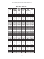
Code 128 Subsets
The three Code 128 character subsets are referred to as Subset A, Subset B, and
Subset C. A subset may be selected in one of two ways:
1. A special Invocation Code can be included in the field data (^FD) string
associated with that bar code.
2. Place the desired Start Code at the beginning of the field data. If no Start
Code is entered, Subset B will be used.
To change subsets within a bar code, place the appropriate Invocation Code at the
appropriate points within the field data string. The new subset will stay in effect until
changed with appropriate Invocation Code. For example, in Subset C, “>7” in the
field data changes the Subset to A.
The table below shows the Code 128 Invocation Codes and Start Characters for the
three subsets.
Invocation
Code
Decimal
Value
><
>0
>=
>1
>2
>3
>4
>5
>6
>7
>8
62
30
94
95
96
97
98
99
100
101
102
Start Characters
103
>9
104
>:
Subset A
Character
Subset B
Character
Subset C
Character
>
>
~
DEL
FNC 3
FNC 2
SHIFT
CODE C
FNC 4
CODE A
FNC 1
CODE B
CODE A
FNC 1
USQ
FNC 3
FNC 2
SHIFT
CODE C
CODE B
FNC 4
FNC 1
Start Code A
Start Code B
(Numeric Pairs give Alpha/Numerics)
(Normal Alpha/Numeric)
Code 128 Invocation Characters
40
ZPL II Programming Guide Volume One: Command Reference for X.10
Example of Code 128 – Subset B
Since Code 128 Subset B is the most commonly used subset, ZPL II defaults to
Subset B if no start character is specified in the data string. This is illustrated in the
following two samples.
The bar codes in the following two samples are identical.
Figure A: Subset B with
no start character
Figure B: Subset B with
start character
The first two commands (^XA^FO100,75) start the label format and set the field
origin (from the upper-left corner) where the bar code field begins – 100 dots across
the x-axis and 75 dots down the y-axis.
The third command (^BCN,100,Y,N,N) calls for a Code 128 bar code to be printed
with no rotation and a height of 100 dots.
Command four (^FDCODE128 in Figure A) and (^FD>:CODE128 in Figure B)
specify the content of the bar code.
Command five (^XZ) indicates the end of the print field and the end of the label
format.
The interpretation line will print below the code with the UCC check digit turned off.
The ^FD command for Figure A does not specify any subset, so Subset B is used. In
Figure B , the ^FD command specifically calls Subset B. Although ZPL II defaults
to Code B, it is a very good practice to include the invocation codes in the command.
Code 128 – Subset B is programmed directly as ASCII text, except for values greater
than 94 decimal and a few special characters:
^
> ~
These characters must be programmed using the invocation codes.
41
ZPL II Programming Guide Volume One: Command Reference for X.10
Example of Code 128 – Subsets A and C
Code 128, Subsets A and C are programmed as pairs of digits, 00-99, in the field
data string (refer to the Code 128 character chart on page 40).
In Subset A, each pair of digits results in a single character being encoded in the bar
code; in Subset C, they are printed as entered. Figure E below is an example of
Subset A. (The “>9” is the Start Code for Subset A.)
Non-integers programmed as the first character of a digit pair (D2) are ignored.
However, non-integers programmed as the second character of a digit pair (2D)
invalidate the entire digit pair, and the pair is ignored. An extra unpaired digit in the
field data string just before a code shift is also ignored.
Figure C and Figure D below are examples of Subset C. Notice that the bar codes in
the figures are identical. In the program code for Figure D, the “D” is ignored and
the 2 is paired with the 4.
Figure C: Subset C,
Normal Data
Figure D: Subset C,
ignoring the Alpha
character
42
Figure E: Subset A
ZPL II Programming Guide Volume One: Command Reference for X.10
^BD
UPS MaxiCode Bar Code
Description: The ^BD command creates a two-dimensional, optically read (not
scanned) code. This symbology was developed by UPS (United Parcel Service).
The code is generated from the information in the ^FD statement which is described
below. Notice that there are no additional parameters for this code and it does not
generate an interpretation line. The ^BY command has no affect on the UPS
MaxiCode Bar Code. However, the ^CV command does work.
Format: ^BDm,n,t
Parameters:
m =
mode
Accepted Values:
2 – Structured carrier message: numeric postal code (U.S.)
3 – Structured carrier message: alphanumeric postal code
(Non-U.S.)
4 – Standard symbol, secretary
5 – Full EEC
6 – Reader program, secretary
Default Value: 2
n =
symbol number
Accepted Values: 1 to 8 may be added in a structured document.
Default Value: 1
t =
total number of symbols
Accepted Values: 1 to 8, representing the total number of symbols in
this sequence.
Default Value: 1
43
ZPL II Programming Guide Volume One: Command Reference for X.10
Example:
^XA
^FO50,50
^CVY
^BD^FH^FD001840152382802[)>_1E01_1D961Z00004951_1DUPS
N_1D_06X610_1D
159_1D1234567_1D1/1_1D_1DY_1D
634 ALPHA DR_1DPITTSBURGH_1DPA_1E_04^FS
^FO30,300^A0,30,30^FDMode2^FS
^XZ
Special Considerations for ^FD when Using ^BD
The ^FD statement is divided into two parts: a High Priority Message (hpm) and a
Low Priority Message (lpm). There are two types of High Priority Messages. One is
for a U.S. Style Postal Code; the other is for a Non-U.S. Style Postal Code. The
syntax for either of these High Priority Messages must be exactly as shown or an
error message will be generated.
Format: ^FD <hpm><lpm>
Parameters:
<hpm> =
high priority message (only applicable in Modes 2 and 3)
Accepted Values: 0 through 9, except where noted.
U.S. Style Postal Code (Mode 2)
<hpm> = aaabbbcccccdddd
aaa = three-digit class of service
bbb = three-digit country zip code
ccccc = five-digit zip code
dddd = four-digit zip code extension. If none exists, four zeros
must be entered (0000).
44
ZPL II Programming Guide Volume One: Command Reference for X.10
Non-U.S. Style Postal Code (Mode 3)
<hpm> = aaabbbcccccc
aaa = three-digit class of service
bbb = three-digit country zip code
ccccc = six-digit zip code (0-9 or A-Z)
<lpm> =
low priority message (only applicable in Modes 2 and 3)
Gs is used to separate fields in a message (0x1D). Rs is used to
separate format types (0x1E). Eot is the end of transmission character.
Message Header
[)>Rs
Transportation Data
Format Header
01Gs96
Tracking Number*
<tracking number>
SCAC*
Gs<SCAC>
UPS Shipper Number
Gs<shipper number>
Julian Day of Pickup
Gs<day of pickup>
Shipment ID Number
Gs<shipment ID number>
Package n/x
Gs<n/x>
Package Weight
Gs<weight>
Address Validation
Gs<validation>
Ship to Street Address
Gs<street address>
Ship to City
Gs<city>
Ship to State
Gs<state>
Rs
Rs
End of Message
Eot
(* Mandatory Data for UPS)
Comments:
•
•
•
•
•
The formatting of <hpm> and <lpm> only apply when using Modes 2 and 3. Mode 4,
for example, will take whatever data is defined in the ^FD command and place it in
the symbol.
UPS requires that certain data be present in a defined manner. When formatting
MaxiCode data for UPS, always use uppercase characters. When filling in the
“fields” in the <lpm> for UPS, follow the data size and types as specified in Guide to
Bar Coding with UPS.
If you do not choose a mode, the default mode will be Mode 2. If you use non-U.S.
postal codes, you will probably get an error message (invalid character or message too
short). When using non-U.S. codes, use mode 3.
ZPL doesn’t automatically change your mode based on the zip code format.
When using special characters, such as Gs, Rs, or Eot, use the ^FH command to tell
ZPL to use the hexadecimal value following the underscore character ( _ ).
45
ZPL II Programming Guide Volume One: Command Reference for X.10
^BE
EAN-13 Bar Code
Description: The ^BE command is similar to the UPC-A bar code. It is widely used
throughout Europe and Japan in the retail marketplace.
The EAN-13 bar code has 12 data characters, one more data character than the
UPC-A code. An EAN-13 symbol contains the same number of bars as the UPC-A,
but encodes a 13th digit into a parity pattern of the left-hand six digits. This 13th
digit, in combination with the 12th digit, represents a country code.
•
•
^BE supports fixed print ratios.
Field data (^FD) is limited to exactly 12 characters. ZPL II automatically truncates or
pads on the left with zeros to achieve the required number of characters.
When using JAN-13 (Japanese Article Numbering), a specialized application of
EAN-13, the first two non-zero digits sent to the printer will always be 49.
•
Format: ^BEo,h,f,g
Parameters:
o
=
orientation
Accepted Values:
N = normal
R = rotated 90 degrees (clockwise)
I = inverted 180 degrees
B = read from bottom up, 270 degrees
Default Value: Current ^FW value
h =
bar code height (in dots)
Accepted Values: 1 to 32000
Default Value: Value set by ^BY
f =
print interpretation line
Accepted Values: Y (yes) or N (no)
Default Value: Y
g =
print interpretation line above code
Accepted Values: Y (yes) or N (no)
Default Value: N
e =
print check digit
Accepted Values: Y (yes) or N (no)
Default Value: N
46
ZPL II Programming Guide Volume One: Command Reference for X.10
Example:
UPC/EAN
Characters
0
1
2
3
4
5
6
7
8
9
Comments: The EAN-13 bar code uses the Mod 10 check-digit scheme for error
checking. For more information on Mod 10, refer to Appendix C in Volume Two.
If additional information about the EAN-13 bar code is required, refer to Appendix
H in Volume Two for AIM, Inc. contact information
47
ZPL II Programming Guide Volume One: Command Reference for X.10
^BF
Micro-PDF417 Bar Code
Description: The ^BF command is a two-dimensional, multi-row, continuous,
stacked symbology identical to PDF417, except it replaces the 17-module-wide
start/stop patterns and left/right row indicators with a unique set of 10-module-wide
row address patterns designed to reduce overall symbol width and to allow linear
scanning at row heights as low as 2X.
Micro PDF417 is designed for applications with a need for improved area efficiency
but without the requirement for PDF417’s maximum data capacity. It may only be
printed in specific combinations of rows and columns up to a maximum of four data
columns by 44 rows.
Field data (^FD) and field hexadecimal (^FH) are limited to:
•
•
•
250 7-bit characters
150 8-bit characters
366 4-bit numeric characters
Format: ^BFo,h,m
Parameters:
o
=
orientation
Accepted Values:
N = normal
R = rotated 90 degrees (clockwise)
I = inverted 180 degrees
B = read from bottom up, 270 degrees
Default Value: Current ^FW value
h =
bar code height (in dots)
Accepted Values: 1 to 9999
Default Value: Value set by ^BY or 10 (if no ^BY value exists)
m =
mode
Accepted Values: 0 to 33 (refer to the Micro-PDF Mode table on page
52)
Default Value: 0 (refer to the Micro-PDF Mode Table on page 52)
48
ZPL II Programming Guide Volume One: Command Reference for X.10
Example: The following ZPL II code will generate the bar code printed at left:
^XA^BY6^BFN,8,3
^FDABCDEFGHIJKLMNOPQRSTUV^FS
^XZ
To encode data into the Micro-PDF417 bar code, follow the procedure below.
Encoding Data into a Micro-PDF417 Bar Code
1. Determine the type of data that will be encoded (e.g., ASCII characters,
numbers, 8-bit data, or a combination).
2. Determine the maximum amount of data that will be encoded within the bar
code (e.g., number of ASCII characters, quantity of numbers, or quantity of
8-bit data characters).
3. Determine the percentage of check digits that will be used within the bar
code. The higher percentage of check digits that are used, the more resistant
the bar code will be to damage – however, the size of the bar code will
increase.
4. Use the Micro-PDF417 Mode Table on the next page with the information
gathered from the questions above to select the mode of the bar code.
49
ZPL II Programming Guide Volume One: Command Reference for X.10
Micro-PDF417 Mode Table
Mode
(M)
0
1
2
3
4
5
6
7
8
9
10
11
12
13
14
15
16
17
18
19
20
21
22
23
24
25
26
27
28
29
30
31
32
33
Number Number
of Data of Data
Columns Rows
1
1
1
1
1
1
2
2
2
2
2
2
2
3
3
3
3
3
3
3
3
3
3
4
4
4
4
4
4
4
4
4
4
4
% of
Max
Cws for
Alpha
EC
Characters
11
14
17
20
24
28
8
11
14
17
20
23
26
6
8
10
12
15
20
26
32
38
44
6
8
10
12
15
20
26
32
38
44
4
64
50
41
40
33
29
50
41
32
29
28
28
29
67
58
53
50
47
43
41
40
39
38
50
44
40
38
35
33
31
30
29
28
50
50
6
12
18
22
30
38
14
24
36
46
56
64
72
10
18
26
34
46
66
90
114
138
162
22
34
46
58
76
106
142
178
214
250
14
Max
Digits
8
17
26
32
44
55
20
35
52
67
82
93
105
14
26
38
49
67
96
132
167
202
237
32
49
67
85
111
155
208
261
313
366
20
ZPL II Programming Guide Volume One: Command Reference for X.10
^BI
Industrial 2 of 5 Bar Code
Description: The ^BI command is a discrete, self-checking, continuous numeric
symbology. Industrial 2 of 5 bar code has been in use the longest of the 2 of 5
family of bar codes. Of that family, the Standard 2 of 5 and Interleaved 2 of 5 bar
codes are also available in ZPL II.
With Industrial 2 of 5, all of the information is contained in the bars. Two bar widths
are employed in this code, the wide bar measuring three times the width of the
narrow bar.
•
•
^BI supports a print ratio of 2.0:1 to 3.0:1.
Field data (^FD) is limited to the width (or length, if rotated) of the label.
Format: ^BIo,h,f,g
Parameters:
o
=
orientation
Accepted Values:
N = normal
R = rotated 90 degrees (clockwise)
I = inverted 180 degrees
B = read from bottom up, 270 degrees
Default Value: Current ^FW value
h =
bar code height (in dots)
Accepted Values: 1 to 32000
Default Value: Value set by ^BY
f =
print interpretation line
Accepted Values: Y (yes) or N (no)
Default Value: Y
g =
print interpretation line above code
Accepted Values: Y (yes) or N (no)
Default Value: N
51
ZPL II Programming Guide Volume One: Command Reference for X.10
Example:
Industrial 2 of 5 Bar Code
Characters
0
1
2
3
4
5
6
7
8
9
Start (internal)
Stop (internal)
Comments: If additional information about the Industrial 2 of 5 bar code is required,
refer to Appendix H in Volume Two for AIM, Inc. contact information.
52
ZPL II Programming Guide Volume One: Command Reference for X.10
^BJ
Standard 2 of 5 Bar Code
Description: The ^BJ command is a discrete, self-checking continuous numeric
symbology.
With Standard 2 of 5, all of the information is contained in the bars. Two bar widths
are employed in this code, the wide bar measuring three times the width of the
narrow bar.
•
•
^BI supports a print ratio of 2.0:1 to 3.0:1.
Field data (^FD) is limited to the width (or length, if rotated) of the label.
Format: ^BJo,h,f,g
Parameters:
o
=
orientation
Accepted Values:
N = normal
R = rotated 90 degrees (clockwise)
I = inverted 180 degrees
B = read from bottom up, 270 degrees
Default Value: Current ^FW value
h =
bar code height (in dots)
Accepted Values: 1 to 32000
Default Value: Value set by ^BY
f =
print interpretation line
Accepted Values: Y (yes) or N (no)
Default Value: Y
g =
print interpretation line above code
Accepted Values: Y (yes) or N (no)
Default Value: N
53
ZPL II Programming Guide Volume One: Command Reference for X.10
Example:
Standard 2 of 5 Bar Code
Characters
0
1
2
3
4
5
6
7
8
9
Start (automatic)
Stop (automatic)
Comments: If additional information about the Standard 2 of 5 bar code is required,
refer to Appendix H in Volume Two for AIM, Inc. contact information.
54
ZPL II Programming Guide Volume One: Command Reference for X.10
^BK
ANSI Codabar
Description: The ^BK command is currently used in a variety of information
processing applications such as libraries, the medical industry, and overnight
package delivery companies. This bar code is also known as USD-4 code, NW-7
and 2 of 7 code. It was originally developed for retail price-labeling use.
Each character in this code is composed of seven elements: four bars and three
spaces. Codabar bar codes use two character sets, numeric and control (start/stop)
characters.
•
•
^BI supports a print ratio of 2.0:1 to 3.0:1.
Field data (^FD) is limited to the width (or length, if rotated) of the label.
Format: ^BKo,e,h,f,g,k,l
Parameters:
o
=
orientation
Accepted Values:
N = normal
R = rotated 90 degrees (clockwise)
I = inverted 180 degrees
B = read from bottom up, 270 degrees
Default Value: Current ^FW value
e =
check digit (not implemented)
Accepted Values: Y (yes) and N (no)
Default Value: N
h =
bar code height (in dots)
Accepted Values: 1 to 32000
Default Value: Value set by ^BY
f =
print interpretation line
Accepted Values: Y (yes) or N (no)
Default Value: Y
g =
print interpretation line above code
Accepted Values: Y (yes) or N (no)
Default Value: N
k =
designates start character
Accepted Values: B, C, D, E, N, T, or *
Default Value: A
55
ZPL II Programming Guide Volume One: Command Reference for X.10
l =
designates stop character
Accepted Values: B, C, D, E, N, T, or *
Default Value: A
Example:
ANSI Codabar Characters
0
2
4
6
8
1
3
5
7
9
Control Characters
:
.
$
/
+
Start/Stop Characters
A
B
C
D
T
N
*
E
Comments: If additional information about the ANSI Codabar bar code is required,
refer to Appendix H in Volume Two for AIM, Inc. contact information.
56
ZPL II Programming Guide Volume One: Command Reference for X.10
^BL
LOGMARS Bar Code
Description: The ^BL command is a special application of Code 39 used by the
Department of Defense (DOD). LOGMARS is an acronym for Logistics
Applications of Automated Marking and Reading Symbols.
•
•
^BI supports a print ratio of 2.0:1 to 3.0:1.
Field data (^FD) is limited to the width (or length, if rotated) of the label.
Format: ^BLo,h,g
Parameters:
o
=
orientation
Accepted Values:
N = normal
R = rotated 90 degrees (clockwise)
I = inverted 180 degrees
B = read from bottom up, 270 degrees
Default Value: Current ^FW value
h =
bar code height (in dots)
Accepted Values: 1 to 32000
Default Value: Value set by ^BY
g =
print interpretation line above code
Accepted Values: Y (yes) or N (no)
Default Value: N
57
ZPL II Programming Guide Volume One: Command Reference for X.10
Example:
LOGMARS Characters
1 2 3 4 5 6 7 8 9
0
A
B
J K
S
C
L
T
U
-
.
D
E
F
G
H
I
M N
O
P
Q
R
V
W
X
Y
* $ / +
%
Z
SPACE
Comments: The LOGMARS bar code produces a “mandatory” check digit using
MOD 43 calculations. For further information, refer to Appendix D in Volume Two.
If additional information about the ANSI Codabar bar code is required, refer to
Appendix H in Volume Two for AIM, Inc. contact information.
58
ZPL II Programming Guide Volume One: Command Reference for X.10
^BM
MSI Bar Code
Description: The ^BM command is a pulse-width modulated, continuous, non-self
checking symbology. It is a variant of the Plessey bar code.
Each character in the MSI bar code is composed of eight elements: four bars and four
adjacent spaces.
•
•
^BI supports a print ratio of 2.0:1 to 3.0:1.
Field data (^FD) is limited to 1 to 14 digits when parameter e is B, C, or D. ^FD is
limited to 1 to 13 digits when parameter e is A, plus a quiet zone.
Format: ^BMo,e,h,f,g,e2
Parameters:
o
=
orientation
Accepted Values:
N = normal
R = rotated 90 degrees (clockwise)
I = inverted 180 degrees
B = read from bottom up, 270 degrees
Default Value: Current ^FW value
e =
check digit selection
Accepted Values:
A = no check digits
B = 1 Mod 10
C = 2 Mod 10
D = 1 Mod 10 and 1 Mod 11
Default Value: B
h =
bar code height (in dots)
Accepted Values: 1 to 32000
Default Value: Value set by ^BY
f =
print interpretation line
Accepted Values: Y (yes) or N (no)
Default Value: Y
g =
print interpretation line above code
Accepted Values: Y (yes) or N (no)
Default Value: N
59
ZPL II Programming Guide Volume One: Command Reference for X.10
e2 =
designates start character
Accepted Values: Y (yes) or N (no)
Default Value: N
Example:
MSI Characters
1
2
3
4
5
6
7
8
9
Comments: If additional information about the MSI bar code is required, refer to
Appendix H in Volume Two for AIM, Inc. contact information.
60
ZPL II Programming Guide Volume One: Command Reference for X.10
^BP
Plessey Bar Code
Description: The ^BP command is a pulse-width modulated, continuous, non-selfchecking symbology.
Each character in the Plessey bar code is composed of eight elements: four bars and
four adjacent spaces.
•
•
^BI supports a print ratio of 2.0:1 to 3.0:1.
Field data (^FD) is limited to the width (or length, if rotated) of the label.
Format: ^BPo,e,h,f,g
Parameters:
o
=
orientation
Accepted Values:
N = normal
R = rotated 90 degrees (clockwise)
I = inverted 180 degrees
B = read from bottom up, 270 degrees
Default Value: Current ^FW value
e =
print check digit
Accepted Values: Y (yes) and N (no)
Default Value: N
h =
bar code height (in dots)
Accepted Values: 1 to 32000
Default Value: Value set by ^BY
f =
print interpretation line
Accepted Values: Y (yes) or N (no)
Default Value: Y
g =
print interpretation line above code
Accepted Values: Y (yes) or N (no)
Default Value: N
61
ZPL II Programming Guide Volume One: Command Reference for X.10
Example:
Plessy Characters
0
8
1
9
2
A
3
B
4
C
5
D
6
E
7
F
Comments: If additional information about the Plessy bar code is required, refer to
Appendix H in Volume Two for AIM, Inc. contact information.
62
ZPL II Programming Guide Volume One: Command Reference for X.10
^BQ
QR Code Bar Code
Description: The ^BQ command produces a matrix symbology consisting of an
array of nominally square modules arranged in an overall square pattern. A unique
pattern at three of the symbol’s four corners assists in determining bar code size,
position, and inclination.
A wide range of symbol sizes is possible along with four levels of error correction.
User-specified module dimensions provide a wide variety of symbol production
techniques.
QR Code Model 1 is the original specification, while QR Code Model 2 is an
enhanced form of the symbology. Model 2 provides additional features and can be
automatically differentiated from Model 1.
Model 2 is the recommended model and should normally be used.
This bar code is printed using field data specified in a subsequent ^FD stream.
Encodable character sets include numeric data, alphanumeric data, 8-bit byte data,
and Kanji characters.
Format: ^BQa,b,c
Parameters:
a =
field position
Accepted Values: Rotation is not supported. ^FW has no effect on
rotation.
Fixed Value: Normal
b =
model
Accepted Values: 1 (original) and 2 (enhanced – recommended)
Default Value: 2
c =
magnification factor
Accepted Values: 1 through 10
Default Value:
1 on 150 dpi printers
2 on 200 dpi printers
3 on 300 dpi printers
6 on 600 dpi printers
63
ZPL II Programming Guide Volume One: Command Reference for X.10
Example:
The following ZPL II code will generate the label printed below.
^XA
^FO20,20^BQN,2,10^FDMM,AAC-42^FS
^XZ
Comments: If additional information about the QR Code bar code is required, refer
to Appendix H in Volume Two for AIM, Inc. contact information.
On the following pages are specific commands for formatting the ^BQ command
with the ^FD statements that contain the information to be coded.
64
ZPL II Programming Guide Volume One: Command Reference for X.10
Considerations for ^FD When Using the QR Code:
QR Switches (formatted into the ^FD field data)
Mixed mode <D>
D = allows mixing of different types of character modes in one code.
Code No. <01 16>
Value = subtracted from the Nth number of the divided code (must be 2
digits).
No. of divisions <02 16>
No. of divisions (must be 2 digits).
Parity data <1 byte>
Value obtained by calculating at the input data (the original input data
before divided byte-by-byte through the EX-OR operation).
Error correction level <H, Q, M, L>
H = Ultra High Reliability Level
Q = High Reliability Level
M = Standard Level (Default)
L = High Density Level
Character Mode <N, A, B, K>
N = Numeric
A = Alphanumeric
Bxxxx = 8-bit Byte mode. Handles the 8-bit Latin/Kana character
set in accordance with JIS X 0201 (character values 0x00 to
0xFF).
xxxx = No. of data characters is represented by 2 bytes of BCD
code
K = Kanji. Only handles Kanji characters in accordance with the
Shift JIS system based on JIS X 0208. This means that all
parameters after the character mode “K” should be 16-bit
characters. If there are any 8-bit characters (such as ASCII
code), an error will occur.
Data character string <Data>
Follows character mode or it will be the last switch in the ^FD
statement.
65
ZPL II Programming Guide Volume One: Command Reference for X.10
Data input <A, M>
A = Automatic input (default). Data character string JIS8 unit,
Shift JIS. When the input mode is automatic input, the binary
codes of 0x80 to 0x9F and 0xE0 to 0xFF cannot be set.
M = Manual input
Two types of data input mode exist: Automatic (A) and Manual (M). If
A is specified, the character mode does not need to be specified. If M
is specified, the character mode must be specified.
^FD Field Data (Normal Mode)
Automatic Data Input (A) with Switches
^FD
<Error correction level>A,
<Data character string>
^FS
Example: QR code, normal mode with automatic data input
^XA
^FO20,20^BQ,2,10^FDQA,0123456789ABCD 2D code^FS
^XZ
<Error Correction level> Q
<Input Mode>
A
<Data character string>
(high)
(automatic setting)
0123456789ABCD 2D code
Manual Data Input (M) with Switches
^FD
<Error correction level>M,
<character mode><data character string>
^FS
Example: QR code, normal mode with manual data input
^XA
^FO20,20^BQ,2,10^FDHM,N123456789012345^FS
^XZ
66
ZPL II Programming Guide Volume One: Command Reference for X.10
<Error Correction level> H
<input mode>
M
<character mode>
N
<data character string>
(ultra-high reliability level)
(manual input)
(numeric data)
123456789012345
Example: QR code, normal mode with standard reliability and manual data input.
^XA
^FO20,20^BQ,2,10^FDMM,AAC-42^FS
^XZ
<Error Correction level> M
<input mode>
M
<character mode>
A
<data character string>
(standard reliability level)
(manual input)
(alphanumeric data)
AC-42
^FD Field Data (Mixed Mode – requires more switches)
Automatic Data Input (A) with Switches
^FD
<Code No.> <No. of divisions> <Parity data>,
<Error correction level> A,
<Data character string>,
<Data character string>,
<
:
>,
<Data character string n**>
^FS
Manual Data Input (M) with Switches
^FD
<Code No.> <No. of divisions> <Parity data>,
<Error correction level> M,
<Character mode 1> <Data character string 1>,
<Character mode 2> <Data character string 2>,
< : >< :
>,
<Character mode n> <Data character string n**>
^FS
n** up to 200 in mixed mode
67
ZPL II Programming Guide Volume One: Command Reference for X.10
Example: QR code, mixed mode with manual data input
^XA
^FO,20,20^BQ,2,10^FDD03048F,LM,N0123456789,A12AABB,B0
006qrcode^FS
^XZ
<Mixed mode identifier>
<Code No.>
<No. of divisions>
<Parity data>
<Error correction level>
<Input mode>
Character mode>
<Data character string>
<Character mode>
<Data character string>
<Character mode>
<Data character string>
D
M
D
M
,
L
M
,
N
,
A
(mixed)
(code number)
(divisions)
(0x8F)
(high-density level)
(manual input)
(numeric data)
0123456789
(alphanumeric data)
12AABB
,
B
(8-bit byte data)
0006 Number of bytes
qrcode
Example: QR Code, Mixed Mode with automatic data Input
^XA
^FO20,20^BQ,2,10^FDD03048F,LA,012345678912AABBqrcode
^FS
^XZ
<Mixed mode identifier>
<Code No.>
<No. of divisions>
<Parity data>
<Error correction level>
<Input mode>
<Data character string>
D
M
D
M
L
A
(mixed)
(code number)
(divisions)
(0x8F)
(high-density level)
(automatic input)
012345678912AABBqrcode
68
ZPL II Programming Guide Volume One: Command Reference for X.10
^BS
UPC/EAN Extensions
Description: The ^BS (UPC/EAN extensions) command is the 2- and 5-digit add-on
used primarily by publishers to create bar codes for ISBN’s (International Standard
Book Numbers). These extensions are handled as separate bar codes.
The ^BS command is designed to be used with ^BU (UPC-A Bar Code) and ^B9
(UPC-E Bar Code).
•
•
^BI supports a fixed print ratio.
Field data (^FD) is limited to exactly 2 or 5 characters. ZPL II automatically
truncates or pads on the left with zeros to achieve required number of characters.
Format: ^BSo,h,f,g
Parameters:
o
=
orientation
Accepted Values:
N = normal
R = rotated 90 degrees (clockwise)
I = inverted 180 degrees
B = read from bottom up, 270 degrees
Default Value: Current ^FW value
h =
bar code height (in dots)
Accepted Values: 1 to 32000
Default Value: Value set by ^BY
f =
print interpretation line
Accepted Values: Y (yes) or N (no)
Default Value: Y
g =
print interpretation line above code
Accepted Values: Y (yes) or N (no)
Default Value: Y
69
ZPL II Programming Guide Volume One: Command Reference for X.10
UPC/EAN Two-Digit Example:
UPC/EAN Two-digit
Characters
0
1
2
3
4
5
6
7
8
9
UPC/EAN Five-Digit Example:
UPC/EAN Five-digit
Characters
70
0
1
2
3
4
5
6
7
8
9
ZPL II Programming Guide Volume One: Command Reference for X.10
Care should be taken in positioning the UPC/EAN extension with respect to the
UPC-A or UPC-E code to insure the resultant composite code is within the UPC
specification.
For UPC codes, with a module width of 2 (default), the Field Origin offsets for the
extension are as follows:
UPC-A
Supplement Origin
X - Offset
Adjustment
Y - Offset
Normal
209 Dots
21 Dots
Rotated
0
209 Dots
Supplement Origin
X - Offset
Adjustment
Y - Offset
Normal
122 Dots
21 Dots
Rotated
0
122 Dots
UPC-E
71
ZPL II Programming Guide Volume One: Command Reference for X.10
Additionally, the bar code height for the extension should be 27 dots (0.135 inches)
shorter than that of the Primary code. A Primary UPC code height of 183 dots
(0.900 inches) would require a extension height of 155 dots (0.765).
The figure below shows an example of how to create a normal UPC-A code for the
value 7000002198 with an extension equal to 04414.
Comments: If additional information about the UPC/EAN bar code is required, refer
to Appendix H in Volume Two for AIM, Inc. contact information.
72
ZPL II Programming Guide Volume One: Command Reference for X.10
^BU
UPC-A Bar Code
Description: The ^BU command is a fixed length, numeric symbology. It is
primarily used in the retail industry for labeling packages. The UPC-A bar code has
11 data characters. The 6 dot/mm, 12 dot/mm, and 24 dot/mm printheads produce
the UPC-A bar code (UPC/EAN symbologies) at 100 percent size. However, an 8
dot/mm printhead will produce the UPC/EAN symbologies at a magnification factor
of 77 percent.
•
•
^BI supports a fixed print ratio.
Field data (^FD) is limited to exactly 11 characters. ZPL II automatically truncates or
pads on the left with zeros to achieve required number of characters.
Format: ^BUo,h,f,g,e
Parameters:
o
=
orientation
Accepted Values:
N = normal
R = rotated 90 degrees (clockwise)
I = inverted 180 degrees
B = read from bottom up, 270 degrees
Default Value: Current ^FW value
h =
bar code height (in dots)
Accepted Values: 1 to 9999
Default Value: Value set by ^BY
f =
print interpretation line
Accepted Values: Y (yes) or N (no)
Default Value: Y
g =
print interpretation line above code
Accepted Values: Y (yes) or N (no)
Default Value: N
e =
print check digit
Accepted Values: Y (yes) and N (no)
Default Value: Y
73
ZPL II Programming Guide Volume One: Command Reference for X.10
The font style of the interpretation line depends on the modulus (width of narrow
bar) selected in ^BY:
6 dot/mm printer: A modulus of 2 dots and greater will print with an OCR-B
interpretation line; a modulus of 1 dot will print font A.
8 dot/mm printer: A modulus of 3 dots and greater will print with an OCR-B
interpretation line; a modulus of 1 or 2 dots will print font A.
12 dot/mm printer: A modulus of 5 dots and greater will print with an OCR-B
interpretation line; a modulus of 1, 2 or 3 dots will print font A.
24 dot/mm printer: A modulus of 9 dots and greater will print with an OCR-B
interpretation line; a modulus of 1 to 8 dots will print font A.
Example:
UPC-A Characters
0
1
2
3
4
5
6
7
8
9
Comments: The UPC-A bar code uses the Mod 10 check digit scheme for error
checking. For further information on Mod 10, refer to Appendix C in Volume Two.
If additional information about the UPC-A bar code is required, refer to Appendix H
in Volume Two for AIM, Inc. contact information.
74
ZPL II Programming Guide Volume One: Command Reference for X.10
^BX
Data Matrix Bar Code
Description: The ^BX command is a two-dimensional matrix symbology which is
made up of square modules arranged within a perimeter finder pattern.
Format: ^BXo,h,s,c,r,f,g
Parameters:
o
=
orientation
Accepted Values:
N = normal
R = rotated 90 degrees (clockwise)
I = inverted 180 degrees
B = read from bottom up, 270 degrees
Default Value: Current ^FW value
h =
dimensional height of individual symbol elements
(one to width of label)
The individual elements are square – this parameter specifies both
module and row height. If this parameter is zero (or not given), the h
parameter (bar height) in ^BY will be used as the approximate symbol
height.
s =
quality level
Accepted Values: 0, 50, 80, 100, 140, 200
Default Value: 0
“Quality” refers to the amount of data that is added to the symbol for
error correction. The AIM specification refers to it as the ECC value.
ECC 50, ECC 80, ECC 100, and ECC 140 use convolution encoding;
ECC 200 uses Reed-Solomon encoding. For new applications, ECC
200 is recommended. ECC 000-140 should only be used in closed
applications where a single party controls both the production and
reading of the symbols and is responsible for overall system
performance.
c =
columns to encode (9 to 49)
Odd values only for quality 0 to 140 (10 to 144); even values only for
quality 200.
75
ZPL II Programming Guide Volume One: Command Reference for X.10
r =
rows to encode (9 to 49)
Odd values only for quality 0 to 140 (10 to 144); even values only for
quality 200.
The number of rows and columns in the symbol will be automatically
determined. The user may wish to force the number of rows and
columns to a larger value to achieve uniform symbol size. In the
current implementation, quality 0 to 140 symbols will always be
square, so the larger of the rows or columns supplied will be used to
force a symbol to that size. If the user attempts to force the data into
too small of a symbol, no symbol will be printed. If a value greater
than 49 is entered, the rows or columns value will be set to zero and the
size will be determined normally. If an even value is entered, it will
generate INVALID-P (invalid parameter). If a value less than 9 but not
0, or if the data is too large for the forced size, no symbol will print; if
^CVY is on, INVALID-L will print.
f =
format ID (0 to 6) – not used with quality set at 200
Accepted Values:
1 = Field data is numeric + space (0..9,”) – No \&’’
2 = Field data is upper-case alphanumeric + space (A..Z,’’) – No
\&’’
3 = Field data is uppercase alphanumeric + space, period, comma,
dash, and slash (0..9,A..Z,“.-/”)
4 = Field data is upper-case alphanumeric + space (0..9,A..Z,’’) –
No \&’’
5 = Field data is full 128 ASCII 7-bit set
6 = Field data is full 256 ISO 8-bit set
Default Value: 6
g =
escape sequence control character
Accepted Values: Any character
Default Value: _ (underscore)
This parameter is only used if quality “200” is specified. It is the
escape character for embedding special control sequences within the
field data. Refer to Field Data (^FD) for Data Matrix for usage.
ECC
LEVEL
ID = 1
ID = 2
ID = 3
ID = 4
ID = 5
ID = 6
0
596
452
394
413
310
271
50
457
333
291
305
228
200
80
402
293
256
268
201
176
100
300
218
190
200
150
131
140
144
105
91
96
72
63
Maximum Field Sizes
76
ZPL II Programming Guide Volume One: Command Reference for X.10
Example:
^XA
^LL500^LH0,0
^FO100,100^BXN,10,200,,,,
^FDZEBRA TECHNOLOGIES CORP,
333 CORPORATE WOODS PKWY
VERNON HILLS, ILLINOIS
60061-3109^FS
^XZ
Effects of ^BY on ^BX
w =
r =
h =
module (no effect – see dimensions of individual symbol elements)
ratio (no effect)
height of symbol
If the dimensions of individual symbol elements are not specified in the
^BD command, the height of symbol value will be divided by the
required rows/columns, rounded, limited to a minimum value of one,
and used as the dimensions of individual symbol elements.
Field Data (^FD) for ^BX
Quality 000 to 140
•
•
The “\&” and “||” can be used to insert carriage return/line feed and back slash as with
PDF417. Other characters in the control character range can only be inserted by using
^FH. Field data is limited to 596 characters for quality “0” to “140.” Excess field
data will cause no symbol to be printed; if ^CVY is on, INVALID-L will be printed.
The field data must correspond to a user-specified format ID or no symbol will be
printed; if ^CVY is on, INVALID-C will be printed.
The maximum field sizes for quality “0” to “140” symbols are shown in the following
table:
Quality 200
•
•
•
If more than 3072 characters are supplied as field data, it is truncated to 3072
characters. This limits the maximum size of a numeric Data Matrix symbol to less
than the 3116 numeric characters that the specification would allow. The maximum
alphanumeric capacity is 2335 and the maximum 8-bit byte capacity is 1556.
If ^FH is used, field hex processing takes place before the escape sequence processing
described below.
The underscore is the default escape sequence control character for quality “200” field
data. A different escape sequence control character may be selected by using
parameter g in the ^BX command.
77
ZPL II Programming Guide Volume One: Command Reference for X.10
The input string escape sequences may be embedded in Quality 200 field data using
the _ character (ASCII 45, underscore) or the character entered in parameter g:
•
•
•
•
•
•
_X is the shift character for control characters (e.g., _@=NUL,_G=BEL,_0 is PAD)
_1 to _3 for FNC characters 1 to 3 (explicit FNC4, upper shift, is not allowed)
FNC2 (Structured Append) must be followed by 9 digits, composed of three 3-digit
numbers with values between 1 and 254, that represent the symbol sequence and file
identifier (for example, symbol 3 of 7 with file ID 1001 is represented by
2214001001)
5NNN is Code Page NNN where NNN is a 3-digit Code Page value (e.g., Code Page
9 is represented by _5009)
_dNNN creates ASCII decimal value NNN for a code word (must be 3 digits)
_ in data is encoded by __ (two underscores)
78
ZPL II Programming Guide Volume One: Command Reference for X.10
^BY
Bar Code Field Default
Description: The ^BY command is used to change the default values for the Narrow
Element Module (Narrow Bar or Space) Width, the Wide Bar to Narrow Bar Width
Ratio and the Bar Height. It can be used as often as necessary within a label format.
Format: ^BYw,r,h
Parameters:
w =
module (narrow bar) width (in dots)
Accepted Values: 1 to 10
Initial Value at Power-up: 2
r =
wide bar to narrow bar width ratio
Accepted Values: 2.0 to 3.0, in .1 increments
(no effect on fixed ratio bar codes)
h =
height of bars (in dots)
Accepted Values: 1 to 32000
Initial Value at Power-up: 10
For parameter r, the actual ratio generated is a function of the number of dots in
parameter w, narrow bar (module). Refer to the table “Bar Code Print Ratios” on the
following page.
For example, set module width (w) to 9 and the ratio (r) to 2.4. The width of the
narrow bar is 9 dots wide and the wide bar is 9 x 2.4 or 21.6 dots. However, since
the printer rounds out to the nearest dot, the wide bar is actually printed at 22 dots.
This produces a bar code with a ratio of 2.44 (22 divided by 9). This ratio is as close
to 2.4 as possible, since only full dots are printed.
Module width and height (w and h) may be changed at anytime with the ^BY
command regardless of the symbology selected.
79
ZPL II Programming Guide Volume One: Command Reference for X.10
Ratio
Module Width in Dots (w)
Selected
(r)
1
2
3
4
5
6
7
8
9
10
2.0
2:1
2:1
2:1
2:1
2:1
2:1
2:1
2:1
2:1
2:1
2.1
2:1
2:1
2:1
2:1
2:1
2:1
2:1
2:1
2:1
2.1:1
2.2
2:1
2:1
2:1
2:1
2.2:1
2.16:1
2.1:1
2.12:1
2.1:1
2.2:1
2.3
2:1
2:1
2.3:1
2.25:1
2.2:1
2.16:1
2.28:1
2.25:1
2.2:1
2.3:1
2.4
2:1
2:1
2.3:1
2.25:1
2.4:1
2.3:1
2.28:1
2.37:1
2.3:1
2.4:1
2.5
2:1
2.5:1
2.3:1
2.5:1
2.4:1
2.5:1
2.4:1
2.5:1
2.4:1
2.5:1
2.6
2:1
2.5:1
2.3:1
2.5:1
2.6:1
2.5:1
2.57:1
2.5:1
2.5:1
2.6:1
2.7
2:1
2.5:1
2.6:1
2.5:1
2.6:1
2.6:1
2.57:1
2.65:1
2.6:1
2.7:1
2.8
2:1
2.5:1
2.6:1
2.75:1
2.8:1
2.6:1
2.7:1
2.75:1
2.7:1
2.8:1
2.9
3.0
2:1
3:1
2.5:1
3:1
2.6:1
3:1
2.75:1
3:1
2.8:1
3:1
2.8:1
3:1
2.85:1
3:1
2.87:1
3:1
2.8:1
3:1
2.9:1
3:1
Comments: Once a ^BY command is entered into a label format, it stays in effect
until another ^BY command is encountered.
80
ZPL II Programming Guide Volume One: Command Reference for X.10
^BZ
POSTNET Bar Code
Description: The POSTNET bar code is used to automate the handling of mail.
POSTNET uses a series of five bars, two tall and three short, to represent the digits 0
to 9.
•
•
^BI supports a print ratio of 2.0:1 to 3.0:1.
Field data (^FD) is limited to the width (or length, if rotated) of the label.
Format: ^BZo,h,f,g
Parameters:
o
=
orientation
Accepted Values:
N = normal
R = rotated 90 degrees (clockwise)
I = inverted 180 degrees
B = read from bottom up, 270 degrees
Default Value: Current ^FW value
h =
bar code height (in dots)
Accepted Values: 1 to 32000
Default Value: Value set by ^BY
f =
print interpretation line
Accepted Values: Y (yes) or N (no)
Default Value: N
g =
print interpretation line above code
Accepted Values: Y (yes) or N (no)
Default Value: N
81
ZPL II Programming Guide Volume One: Command Reference for X.10
Example:
POSTNET
Characters
0
1
2
3
4
5
6
7
8
9
Comments: If additional information about the POSTNET Bar Code is required,
refer to Appendix H in Volume Two for AIM, Inc. contact information, or contact the
United States Postal Service and ask for Publication 25 – Designing Letter Mail,
which includes a full specification for POSTNET. You can also download
Publication 25 from the URL below:
http://pe.usps.gov/cpim/ftp/pubs/pub25/pub25.pdf
82
ZPL II Programming Guide Volume One: Command Reference for X.10
^CC ~CC
Change Caret
Description: The ^CC and ~CC commands are used to change the format command
prefix. The default prefix is the caret (^).
Format: ^CCx or ~CCx
Parameters:
x =
caret character change
Accepted Values: any ASCII character
Default Value: a parameter is required. If no parameter is entered, the
next character received will be the new prefix character.
Example:
^XA
^CC/
/XZ
Comments: In the above example, the forward slash (/) is set at the new prefix.
Note the /XZ ending tag uses the new designated prefix character (/).
83
ZPL II Programming Guide Volume One: Command Reference for X.10
^CD ~CD
Change Delimiter
Description: The ^CD and ~CD commands are used to change the ZPL II delimiter
character. This character is used to separate parameter values associated with several
ZPL II commands. The default delimiter is a comma (,).
Format: ^CDa or ~CDa
Parameters:
a =
delimiter character change
Accepted Values: any ASCII character
Default Value: a parameter is required. If no parameter is entered, the
next character received will be the new prefix character.
Example:
^XA
^CD.
^XZ
Comments: In the above example, the delimiter character is changed to a period (.).
84
ZPL II Programming Guide Volume One: Command Reference for X.10
^CF
Change Alphanumeric Default Font
Description: You can use the ^CF command to keep your programs simple. The
^CF command sets the default font used in your printer.
Format: ^CFf,h,w
Parameters:
f =
specified default font
Accepted Values: A through H, and numerals 0 to 9.
Initial Value at Power-up: A
h =
individual character height (in dots)
Accepted Values: 0 to 32000
Initial Value at Power-up: 9
w =
individual character width (in dots)
Accepted Values: 0 to 32000
Initial Value at Power-up: 5 or last permanent saved value.
Parameter f specifies the default font for every alphanumeric field. Parameter h is
default height for every alpha field, parameter w is default width value for every
alpha field.
The default alphanumeric font is A. If you do not change the alphanumeric default
font (^CF command) and do not use any alphanumeric field command (^Af) or enter
an invalid font value, any data you specify will print in font A.
Defining only the height or width forces the magnification to be proportional to the
parameter defined. If neither value is defined, the last ^CF values given or the
default ^CF values for height and width are used.
85
ZPL II Programming Guide Volume One: Command Reference for X.10
Example:
This example specifies the desired font information once using the ^CF command.
^XA
^CF0,89
^FO120,50^FDA Guide to^FS
^FO120,150^FDthe ZPL II^FS
^FO120,250^FDProgramming^FS
^FO120,350^FDLanguage
^XZ
Comments: Any font in the printer, including downloaded fonts, EPROM stored
fonts, and fonts A through Z and 1 to 9 can also be selected with ^CW.
86
ZPL II Programming Guide Volume One: Command Reference for X.10
^CI
Change International Font
Description: Zebra printers can print all fonts using various international character
sets: USA1, USA2, UK, Holland, Denmark/Norway, Sweden/Finland, Germany,
France 1, France 2, Italy, Spain, and miscellaneous.
ZPL II follows the ISO standards for international characters.
The ^CI command enables you to call up the international character set you want to
use for printing. You can mix character sets on a label. The following page shows
the international character sets available.
This command allows character remapping. Any character within a font can be
remapped to a different numerical position.
Format: ^CIa,s1,d1,s2,d2,...
Parameters:
a =
s1 =
desired character set
Accepted Values:
0 = U.S.A. 1
1 = U.S.A. 2
2 = UK
3 = Holland
4 = Denmark/Norway
5 = Sweden/Finland
6 = Germany
7 = France 1
8 = France 2
9 = Italy
10 = Spain
11 = miscellaneous
12 = Japan (ASCII with Yen symbol)
13 = IBM Code Page 850
14 = 16 bit (Unicode) encoded scalable fonts*
15 = Shift-JIS for scalable Japanese fonts**
16 = EUC-Kanji for scalable fonts
17 = Unicode (for Unicode encoded fonts)
18 to 23 = Reserved
24 = 8-bit access to Unicode encoded fonts
Initial Value at Power-up: last permanent value saved.
source 1 (character position to be remapped)
Accepted Values: decimals 0 to 255
87
ZPL II Programming Guide Volume One: Command Reference for X.10
d1 =
destination 1 (new position for the character referred to in s1)
Accepted Values: decimals 0 to 255
s2 =
source 2 (character position to be remapped)
Accepted Values: decimals 0 to 255
d2 =
destination 2 (new position for the character referred to in s2)
Accepted Values: decimals 0 to 255
… =
continuation of pattern
Up to 256 source and destination pairs can be entered in this command.
*The encoding is controlled by the conversion table (*.DAT). The table generated by ZTools™ is the
TrueType font’s internal encoding (Unicode).
** Shift-JIS encoding converts Shift-JIS to JIS and then looks up the JIS conversion in JIS.DAT. This
table must be present for Shift-JIS to function
Example:
This example re-maps the Euro symbol (21) to the Dollar sign value (36). In this
way, when the dollar sign character is sent to the printer, the Euro symbol will print.
The Euro symbol value, 15 Hex, equals 21 decimal, and the Dollar sign value, 24
Hex, equals 36 decimal.
^CI0,21,36
International Character Sets
Comments: The “space” character cannot be remapped for any font.
88
ZPL II Programming Guide Volume One: Command Reference for X.10
^CM
Change Memory Letter Designation
Description: The ^CM command allows the user to reassign a letter designation to
the printer’s memory devices. If a format already exists, you can reassign the
memory device to the corresponding letter without being forced to alter or recreate
the format itself.
Using this command will impact every subsequent command that refers to specific
memory locations.
Format: ^CMa,b,c
Parameters:
a =
memory alias letter designation
Accepted Values: B:, E:, R:, none
Default Value: B:
b =
memory alias letter designation
Accepted Values: B:, E:, R:, none
Default Value: E:
c =
memory alias letter designation
Accepted Values: B:, E:, R:, none
Default Value: R:
Comments: If two or more parameters specify the same letter designator, all letter
designators will be set to their default values.
If any of the parameters are out of specification, the command will be ignored.
89
ZPL II Programming Guide Volume One: Command Reference for X.10
Example:
This example designates letter E: to point to the B: memory device, and the letter B:
to point to the E: memory device.
^XA^CME,B,R^JUS^XA
This example resets all letter designations to point to themselves.
^XA^CME,B,B^JUS^XA
This example sets all letter designation to point to themselves.
^XA^CM,,R^JUS^XZ
Comments: It is recommended that after entering the ^CM command, ^JUS is
entered to save changes to EEPROM. Any duplicate parameters entered will reset
the letter designations back to the default.
90
ZPL II Programming Guide Volume One: Command Reference for X.10
^CO
Cache On
Description: The ^CO command is used to change the size of the character cache.
By definition, a “character cache” (from here on referred to as cache) is a portion of
the DRAM reserved for storing scalable characters. All printers have a default 22K
cache that is always turned on. The maximum single character size that can be
stored, without changing the size of the cache, is 450 dots by 450 dots.
There are two types of fonts used in Zebra printers: bitmapped and scalable. Letters,
numbers, and symbols in a bitmapped font have a fixed size. For example: 10
points, 12 points, 14 points, etc. On the other hand, scalable fonts are not fixed in
size. Their sizes are user-selectable.
Because their size is fixed, bitmapped fonts can be moved quickly to the label. By
contrast, scalable fonts are much slower because each character is built on an
as-needed basis before it is moved to the label. By storing scaled characters in a
“cache” they can be recalled at a much faster speed.
The number of characters that can be stored in the cache depends on two factors: the
size of the cache (memory) and the size of the character (in points) being saved. The
larger the point size, the more space in the cache it uses. The default cache stores
every scalable character that is requested for use on a label(s). If the same character,
with the same rotation and size is used again, it is quickly retrieved from the cache.
It is quite possible that after a while the print cache could become full. Once the
cache is full, space for new characters is obtained by eliminating an existing
character from the print cache. Existing characters are eliminated by determining
how often they have been used. This is done automatically. For example, a 28 point
“Q” that was used only once would be a good candidate for elimination from the
cache.
Maximum size of a single print cache character is 1500 dots by 1500 dots. It would
require a cache of 300K for this.
When the cache is too small for the desired style, smaller characters may appear but
larger characters will not. If possible, increase the size of the cache.
91
ZPL II Programming Guide Volume One: Command Reference for X.10
Format: ^COa,b,c
Parameters:
a =
cache on
Accepted Values: Y (yes) or N (no)
Default Value: Y
b =
amount of additional memory to be added to cache (in K)
Accepted Values: any size up to total memory available
Default Value: 40K
c =
cache type
Accepted Values:
0 = cache buffer (normal fonts)
1 = internal buffer (recommended for Asian fonts
Default Value: 0
Example:
To resize the print cache to 62K, assuming a 22K existing cache:
^COY,40
To resize the print cache to 100K, assuming a 22K existing cache:
^COY,78
Print Cache Performance:
For printing large characters, memory added to the cache by the ^CO command is
not physically added to the 22K cache already in the printer. In the second example
above, the resultant 100K cache is actually two separate blocks of memory, 22K and
78K.
Since large characters need contiguous blocks of memory, a character requiring a
cache of 90K would not be completely stored because neither portion of the 100K
cache is big enough. Therefore, if large characters are needed, the ^CO command
should reflect the actual size of the cache you need.
Increasing the size of the cache will improve the performance in printing scalable
fonts. However, the performance will start to go down if the size of the cache
becomes large and contains too many characters. The performance gained will be
lost because of the time involved in searching through the cache for all of the
characters.
92
ZPL II Programming Guide Volume One: Command Reference for X.10
Comments: The cache can be resized as often as needed. Any characters in the
cache when it is resized are lost. Memory used for the cache reduces the space
available for label bitmaps, graphic, downloaded fonts, etc.
Some Asian fonts require an internal working buffer which is much larger than the
normal cache. Since most fonts do not require this larger buffer, it is now a
selectable configuration option. Printing with the Asian fonts will greatly reduce the
printer memory available for labels, graphics, fonts and formats.
93
ZPL II Programming Guide Volume One: Command Reference for X.10
^CT ~CT
Change Tilde
Description: The ^CT and ~CT commands are used to change the control command
prefix. The default prefix is the tilde (~).
Format: ^CTa or ~CTa
Parameters:
a =
change control command character
Accepted Values: any ASCII character
Default Value: Parameter is required. If no value is entered, the next
character received will be the new prefix character.
Example:
^XA
^CT+
+DGR:GRAPHIC.GRF,04412,010
^XZ
94
ZPL II Programming Guide Volume One: Command Reference for X.10
^CV
Code Validation
Description: The ^CV command acts as a switch to turn the code validation function
on and off. When this command is turned on, all bar code data will be checked for
the following error conditions:
•
•
•
•
•
Character not in character set
Check digit incorrect
Data field too long (too many characters)
Data field too short (too few characters)
Parameter string contains incorrect data or missing parameter
When invalid data is detected, an error message and code will be printed in reverse
image in place of the bar code. The message will read “INVALID - X” where “X” is
one of the following error codes:
•
•
•
•
•
C = Character not in character set
E = Check digit incorrect
L = Data field too long
S = Data field too short
P = Parameter (occurs only on select bar codes)
Once turned on, the ^CV command will remain active from format to format until
turned off by another ^CV command or the printer is turned off. The command is
not permanently saved.
Format: ^CVa
Parameters:
a =
code validation
Accepted Values: Y (yes) or N (no)
Default Value: N
95
ZPL II Programming Guide Volume One: Command Reference for X.10
Example:
The top sample in both columns shows a correctly printed bar code. It is followed by
an example of the error messages.
Comments: If more than one error exists, the first error detected will be the one
displayed.
The ^CV command tests the integrity of the data encoded into the bar code. It is not
used for (or to be confused with) testing the scan-integrity of an image or bar code.
96
ZPL II Programming Guide Volume One: Command Reference for X.10
^CW
Font Identifier
Description: All built-in fonts have a one-character identifier. The ^CW command
assigns a single alphanumeric character (A through Z and 0 to 9) to a font stored in
DRAM, memory card, EPROM or Flash.
If the assigned character is the same as that of a built-in font, the downloaded font is
used in place of the built-in font. The new font will be printed on the label wherever
the format calls for the built-in font. If used in place of a built-in font, the change is
only in effect until power is turned off.
If the assigned character is different, the downloaded font is used as an additional
font. The assignment will remain in effect until a new command is issued or the
printer turned off.
Format: ^CWa,d:o.x
Parameters:
a =
letter of existing font to be substituted, or new font to be added
Required is a one-character entry.
d =
destination of device to store font in (optional)
Accepted Values: E:, B:, R:, Z:
Default: R:
o =
name of the downloaded font to be substituted for the built-in, or
as an additional font (1 to 8 alphanumeric characters)
Accepted Values: any name up to 8 characters
Default: If no name is entered, UNKNOWN is used.
x =
3-character extension
Fixed: .FNT
97
ZPL II Programming Guide Volume One: Command Reference for X.10
Example:
To use MYFONT.FNT stored in DRAM whenever a format calls for Font A:
^XA^CWA,R:MYFONT.FNT^XZ
To use MYFONT.FNT stored in DRAM as additional Font Q:
^XA^CWQ,R:MYFONT.FNT^XZ
To use NEWFONT.FNT stored in DRAM whenever a format calls for font F:
^XA^CWF,R:NEWFONT.FNT^XZ
Label listing Before Assignment
Label Listing After Assignment
98
ZPL II Programming Guide Volume One: Command Reference for X.10
~DB
Download Bitmap Font
Description: The ~DB command sets the printer to receive a downloaded bitmap
font, defines native cell size, baseline, space size, and copyright.
This command consists of two portions, a ZPL II command which defines the font
and a structured data segment which defines each character of the font.
Format: ~DBd:o.x,a,h,w,base,space,#char,©,data
Parameters:
d =
destination drive to store font
o =
name of font
Accepted Values: 1 to 8 alphanumeric characters
Default Value: UNKNOWN.FNT
x =
extension
Fixed: .FNT
a =
orientation of native font
Fixed: Normal
h =
maximum height of cell (in dots)
w =
maximum width of cell (in dots)
base =
dots from top of cell to character baseline
space =
width of space or non-existent characters
#char =
number of characters in font
Maximum characters allowed is 256. This must match the number of
characters being downloaded.
© =
\ data =
copyright holder
Maximum length of text string is 63 characters.
structured ASCII data that defines each character in the font
The # symbol signifies character code parameters which are separated
with periods. The character code is from 1 to 4 characters to allow for
large international character sets to be downloaded to the printer.
99
ZPL II Programming Guide Volume One: Command Reference for X.10
The data structure is:
#xxxx.h.w.x.y.i.data
#xxxx = character code
h = bitmap height (in dot rows)
w = bitmap width (in dot rows)
x = x-offset (in dots)
y = y-offset (in dots)
i = typesetting motion displacement (width including
inter-character gap of a particular character in the font)
data = hexadecimal bitmap description
Example:
The following is an example of how to use the ~DB command. It shows the first two
characters of a font being downloaded to DRAM.
~DBR:TIMES.FNT,N,5,24,3,10,2,ZEBRA 1992,
#0025.5.16.2.5.18.
OOFF
OOFF
FFOO
FFOO
FFFF
#0037.4.24.3.6.26.
OOFFOO
OFOOFO
OFOOFO
OOFFOO
100
ZPL II Programming Guide Volume One: Command Reference for X.10
~DE
Download Encoding
Description: The standard encoding for TrueType® Windows™ fonts is always
Unicode. Therefore, the ZPL field data must be converted from some other encoding
to Unicode. The required translation table is downloaded with the ~DE command.
These tables are provided with ZTools for Windows.
Format: ~DEn,s,data
Parameters:
n =
table name
Accepted Values: A destination indicator (any non-volatile RAM
device) followed by the table name, up to 8 characters.
Default Value: If a name is not entered, UNKNOWN is used.
s =
table size
Accepted Values: The number of memory bytes required to hold the
Zebra downloadable format of the font.
Default Value: If an incorrect value or no value is entered, the
command is ignored.
data =
data string
Accepted Values: a string of ASCII hexadecimal values.
Default Value: If no data is entered, the command is ignored.
101
ZPL II Programming Guide Volume One: Command Reference for X.10
Example:
~DER:JIS.DAT,27848,300021213001...
(27848 2-digit hexadecimal values)
Comments: For more information on ZTools for Windows, refer to the program
documentation included with the software.
102
ZPL II Programming Guide Volume One: Command Reference for X.10
^DF
Download Format
Description: The ^DF command saves ZPL II format commands as text strings to be
later merged using ^XF with variable data. The format to be stored may contain
Field Number (^FN) commands to be referenced when recalled.
While use of stored formats will reduce transmission time, no formatting time is
saved – this command saves ZPL II as text strings formatted at print time.
If the image name is omitted, the name and extension UNKNOWN.ZPL will be
used. Enter the ^DF stored format command immediately after the ^XA command,
then enter the format commands to be saved.
Format: ^DFd:o.x
Parameters:
d =
destination device to store image
Fixed: always a non-volatile RAM device
o =
image name
Accepted Values: 1 to 8 alphanumeric characters
Default Value: If a name is not entered, UNKNOWN is used.
x =
filename extension
Fixed: .ZPL
103
ZPL II Programming Guide Volume One: Command Reference for X.10
Example:
The following is an example of using the ^DF command to download and store ZPL
II text strings to non-volatile RAM. The name used to store the text strings is
STOREFMT.ZPL.
^XA
^DFR:STOREFMT.ZPL^FS
^FO25,25^AD,36,20^FN1^FS
^FO165,25^AD,36,20^FN2^FS
^FO25,75^AB,22,14^FDBUILT BY^FS
^FO25,125^AE,28,15^FN1^FS
^XZ
The sample shown below is generated by using the ^XF (Recall Format) command
to recall this format.
Comments: A format containing a ^DF will not print. Results are undefined for any
commands that appear prior to the ^DF in a format.
104
ZPL II Programming Guide Volume One: Command Reference for X.10
~DG
Download Graphics
Description: The ~DG (Download Graphic) command performs the following
functions:
1. Puts the printer into graphics mode.
2. Names the graphic (this name is used to recall it into a label).
3. Defines the size of the graphic.
4. Downloads the hexadecimal string to the printer.
Format: ~DGd:o.x,t,w,data
Parameters:
d =
destination device to store image
Accepted Values: a non-volatile RAM device
Default Value: R: (DRAM)
o =
image name
Accepted Values: 1 to 8 alphanumeric characters
Default Value: If no name is entered, UNKNOWN is used.
x =
filename extension
Fixed: .GRF
t =
total number of bytes in graphic
Refer to the formula on the following page.
w =
number of bytes per row
Refer to the formula on the following page.
data =
ASCII hexadecimal string defining image
The data string defines the image and is an ASCII hexadecimal
representation of the image. Each character represents a horizontal
nibble of four dots.
105
ZPL II Programming Guide Volume One: Command Reference for X.10
The t parameter can be determined by using the following formula:
where x is the width of the graphic in millimeters, y is the height of the graphic in
millimeters and dots/mm is the print density of the printer being programmed.
For example, to determine the correct t parameter for a graphic 8mm wide, 16mm
high and a print density of 8 dots/mm, the formula works this way:
Raise any portion of a byte to the next whole byte.
The w parameter (the width in terms of bytes per row) can be determined by using
the following formula:
where x is the width of the graphic in millimeters and dots/mm is the print density of
the printer being programmed.
For example, to determine the correct w parameter for a graphic 8mm wide and a
print density of 8 dots/mm, the formula works this way:
Raise any portion of a byte to the next whole byte.
Parameter w is the first value in the t calculation.
Parameter data is a string of hexadecimal numbers sent as a representation of the
graphic image. Each hexadecimal character represents a horizontal nibble of four
dots. For example, if the first four dots of the graphic image to be created should be
white and the next four black, the dot by dot binary code would be 00001111. The
hexadecimal representation of this binary value would be 0F. The entire graphic
image is coded in this way. The complete graphic image is sent as one long
continuous string of hexadecimal values.
106
ZPL II Programming Guide Volume One: Command Reference for X.10
Example:
The following is an example of using the ~DG command to load a checkerboard
pattern into DRAM. The name used to store the graphic is SAMPLE.GRF.
~DGR:SAMPLE.GRF,00080,010,
FFFFFFFFFFFFFFFFFFFF
8000FFFF0000FFFF0001
8000FFFF0000FFFF0001
8000FFFF0000FFFF0001
FFFF0000FFFF0000FFFF
FFFF0000FFFF0000FFFF
FFFF0000FFFF0000FFFF
FFFFFFFFFFFFFFFFFFFF
Comments: Do not use spaces or periods when naming your graphics. Always use
different names for different graphics.
If two graphics with the same name are sent to the printer, the first graphic will be
erased and replaced by the second graphic.
107
ZPL II Programming Guide Volume One: Command Reference for X.10
~DN
Abort Download Graphic
Description: After decoding and printing the number of bytes in parameter t of the
^DG command, the printer returns to normal print mode. Graphics Mode can be
aborted and normal printer operation resumed by using the ~DN (Abort Download
Graphic) command.
Format: ~DN
Comments: If you need to stop a graphic from downloading, you should abort the
transmission from the host device. To clear the ~DG command, however, you must
send a ~DN command.
108
ZPL II Programming Guide Volume One: Command Reference for X.10
~DS
Download Scalable Font
Description: The ~DS command is used to set the printer to receive a downloadable
scalable font and defines the size of the font in bytes.
The ~DS command, and its associated parameters, are the result of converting a
vendor supplied font for use on a Zebra printer. The conversion is done using the
Zebra utility program ZTools for Windows. The program is available from Zebra
Technologies Corporation. Additionally, you cannot send an Intelifont directly to
the printer; you must convert any Intelifonts using the ZTools for Windows utility.
Format: ~DSd:o.x,s,data
Parameters:
d =
destination device to store image
Accepted Values: a non-volatile RAM device
Default Value: R: (DRAM)
o =
name of image
Accepted Values: 1 to 8 alphanumeric characters
Default Value: if no name is entered, UNKNOWN is used.
x =
filename extension
Fixed: .FNT
s =
size of font in bytes
This number is generated by ZTools and should not be changed.
data =
ASCII hexadecimal string that defines font
This number is generated by ZTools and should not be changed.
Example:
The following example shows the first three lines of a scalable font which has been
converted using the ZTools for Windows program and is ready to be downloaded to
the printer. If necessary, the destination and object name can be changed.
~DSB:CGTIMES.FNT,37080,
OOFFOOFFOOFFOOFF
FFOAECB28FFFOOFF
Comments: Downloaded scalable fonts are not checked for integrity. If they are
corrupt, they will cause unpredictable results at the printer.
109
ZPL II Programming Guide Volume One: Command Reference for X.10
~DT
Download TrueType Font
Description: The ZTools for Windows program must be used to convert a TrueType
font to a Zebra-downloadable format. This program creates a downloadable file that
includes a ~DT command. Once downloaded, the font will function just like the
earlier Intelifont software.
Format: ~DTf,s,data
Parameters:
f =
font name
Accepted Values: A destination indicator (any non-volatile RAM
device; default device is R:) followed by the TrueType name, up to 8
characters.
Default Value: If no name is entered, UNKNOWN is used.
s =
font size
Accepted Values: The number of memory bytes required to hold the
Zebra downloadable format of the font
Default Value: If an incorrect value or no value is entered, the
command is ignored.
data =
data string
Accepted Values: a string of ASCII hexadecimal values (2 hex
digits/byte). The total number of 2-digit values must match s.
Default Value: If no data is entered, the command is ignored.
Example:
~DTR:FONT,52010,00AF01B0C65E...
(52010 2-digit hexadecimal values)
110
ZPL II Programming Guide Volume One: Command Reference for X.10
~DU
Download Unbounded TrueType Font
Description: Some international fonts have more than 256 printable characters.
These fonts are supported as “Large TrueType Fonts” such as Asian fonts, and are
downloaded to the printer with the ~DU command. The ZTools for Windows
program must be used to convert the “Large TrueType Fonts” to a Zebradownloadable format.
The Field Block (^FB) command cannot support the large TrueType fonts.
Format: ~DUf,s,data
Parameters:
f =
font name
Accepted Values: A destination indicator (any non-volatile RAM
device; default device is R:) followed by the TrueType name, up to 8
characters.
Default Value: If no name is entered, UNKNOWN is used.
s =
font size
Accepted Values: The number of memory bytes required to hold the
Zebra downloadable format of the font.
Default Value: If no data is entered, the command is ignored.
data =
data string
Accepted Values: a string of ASCII hexadecimal values (2 hex
digits/byte). The total number of 2-digit values must match s.
Default Value: If no data is entered, the command is ignored.
Example:
~DUR:KANJI,86753,60CA017B0CE7...
(86753 2-digit hexadecimal values)
111
ZPL II Programming Guide Volume One: Command Reference for X.10
~DY
Download Graphics
Description: ~DY downloads to the printer graphic objects in any supported format.
This command can be used in place of ~DG for more saving and loading options.
Format: ~DYf,b,x,t,w,data
Parameters:
f =
font name
b =
format downloaded in data field (f)
a = uncompressed bitmap (.GRF, ASCII)
b = uncompressed bitmap (.GRF, binary)
c = AR-compressed bitmap (.GRF, compressed binary)
p = PNG image (.PNG)
x =
extension of stored graphic
G = raw bitmap (.GRF)
P = store as compressed (.PNG)
t =
total number of bytes in graphic
.GRF images: the size after decompression into memory.
.PNG images: the size of the .PNG file.
w =
data =
total number of bytes per row
.GRF images: number of bytes per row.
.PNG images: this data is ignored – dimensions are encoded directly
into .PNG data.
data
ASCII hexadecimal encoding, ZB64, or binary data, depending on b.
a, p = ASCII hexadecimal or ZB64
b, c = binary
When binary data is sent, all control prefixes and flow control
characters will be ignored until the total number of bytes needed for the
graphic format is received.
Comments: Parameter b, option c is only used by Zebra’s Bar-One® software.
For more information on ZB64 encoding and compression, refer to Appendix I in
Volume Two.
112
ZPL II Programming Guide Volume One: Command Reference for X.10
~EF
Erase Stored Formats
Description: The ~EF command erases all stored formats.
Format: ~EF
Comments: The ~EF command is no longer recommended for use! It is
recommended that the ^ID (Object Delete) command is used to selectively delete
stored formats.
~EG
Erase Download Graphics
Description: The ~EG command is used to delete all graphic images (label format
images and hexadecimal images) from DRAM. This command will erase everything
in R:, E:, and B: memory.
Format: ~EG
Comments: The ~EG command is no longer recommended for use! It is
recommended that the ^ID (Object Delete) command is used to selectively delete
stored graphics.
113
ZPL II Programming Guide Volume One: Command Reference for X.10
^FB
Field Block
Description: The ^FB command allows you to print text into a defined “block type ”
format. This command formats an ^FD text string into a block of text using the
origin, font, and rotation specified for the text string. This command also contains an
automatic word-wrap function.
Format: ^FBa,b,c,d,e
Parameters:
a =
width of text block line (in dots)
Accepted Values: 1 to the width of the label (or 9999)
Default Value: 0
If the value is less than font width or not specified, text will not print.
b =
maximum number of lines in text block
Accepted Values: 1 to 9999
Default Value: 1
Text exceeding the maximum number of lines will overwrite the last
line. Changing the font size will automatically increase or decrease the
size of the block.
c =
add or delete space between lines (in dots)
Accepted Values: -9999 to 9999
Default Value: 0
Numbers are considered to be positive unless preceded by a minus sign.
Positive values add space; negative values delete space.
d =
text justification
Accepted Values: L (left), C (center), R (right), J (justified)
Default Value: L
Last line is left-justified if J is used.
e =
hanging indent (in dots)
Determines the indent of second and remaining lines.
Accepted Values: 0 to 9999
Default Value: 0
114
ZPL II Programming Guide Volume One: Command Reference for X.10
Example:
The following are examples of how the ^FB command affects the field data.
^XA^CF0,30,30^FO25,50
^FB250,4,,
^FD“FD” statement that IS preceded by an “FB”
command.^FS
^XZ
“FD” statement
that IS preceded by
an “FB” command.
^XA^CF0,30,30^FO25,50
^FD“FD” statement that IS NOT preceded by an “FB”
command.^FS
^XZ
“FD” statement that IS NOT preceded by an “FB” comm
115
ZPL II Programming Guide Volume One: Command Reference for X.10
Comments on the ^FB Command
The following scheme can be used to facilitate special functions.
“ \& ” = carriage return/line feed
“ \(*)” = soft hyphen (word break with a dash)
“ \\ ” = \ (See Item 1 below)
Item 1: ^CI13 must be selected in order to print a \.
Item 2: If a soft hyphen is placed near the end of a line, the hyphen will be printed.
If it is not placed near the end of the line, it will be ignored.
(*) = Any alphanumeric character.
•
•
•
•
•
•
•
If a word is too long to print on one line by itself (and no soft hyphen is specified), a
hyphen will automatically be placed in the word at the right edge of the block. The
remainder of the word will be on the next line. The position of the hyphen depends on
word length not a syllable boundary. Placing a soft hyphen with a word controls
where the hyphenation will occur.
Maximum data string length is 3K including control characters and carriage
return/line feeds.
Normal carriage return/line feeds and “word spaces” at line breaks are discarded.
When using ^FT (Field Typeset), ^FT uses the baseline origin of the last possible line
of text. Increasing the font size will cause the text block to increase in size from
bottom to top. This could cause label to print past the top of label.
When using ^FO (Field Origin), increasing the font size will cause the text block to
increase in size from top to bottom.
If an ^SN is used instead of an ^FD, the field will not print.
An ^FS terminates an ^FB statement. Each block requires its own ^FB command.
116
ZPL II Programming Guide Volume One: Command Reference for X.10
^FC
Field Clock (for Real Time Clock)
Description: The ^FC command is used to set the clock-indicators (delimiters) and
the clock mode, for use with the Real Time Clock hardware. This command must be
included within each label field command string each time the Real Time Clock
values are required within the field.
Format: ^FCa,b,c
Parameters:
a =
primary clock indicator character
Accepted Values: Any ASCII character
Default Value: %
b =
secondary clock indicator character
Accepted Values: Any ASCII character
Default Value: none – this value cannot be the same as a or c.
c =
tertiary clock indicator character
Accepted Values: Any ASCII character
Default Value: none – this value cannot be the same as a or b.
Comments: The ^FC command will be ignored if the Real Time Clock hardware is
not present.
117
ZPL II Programming Guide Volume One: Command Reference for X.10
^FD
Field Data
Description: The ^FD command defines the data string for the field. The field data
can be any printable character except those used as command prefixes (^ and ~).
Format: ^FDa
Parameters:
a =
data to be printed
Accepted Values: any ASCII string up to 3072 characters.
Default Value: none – a string of characters must be entered.
Comments:
The ^ and ~ characters can be printed by changing the prefix characters – refer to the
~CC and ~CT commands. The new prefix characters cannot be printed.
Characters with codes above 127, or the ^ and ~ characters can be printed using the
^FH and ^FD commands.
For printing special functions, the following scheme is used:
\& = carriage return/line feed
\(*) = soft hyphen (word break with a dash)
\\ = backslash (\)
•
•
^CI13 must be selected in order to print a \.
If a soft hyphen is placed near the end of a line, the hyphen will be printed. If it is not
placed near the end of the line, it will be ignored.
118
ZPL II Programming Guide Volume One: Command Reference for X.10
^FH
Field Hexadecimal Indicator
Description: The ^FH command allows you to enter the hexadecimal value for any
character directly into the ^FD statement. The ^FH command must precede each
^FD command in which it will be used.
Within the ^FD statement, the HEX indicator must precede each hexadecimal value.
The default hexadecimal indicator is _ (underscore). There must be a minimum of
two characters designated to follow the underscore. The a parameter can be added
when a different hexadecimal indicator is needed.
This command can be used with any of the commands that have field data (i.e. ^FD,
^FV (Field Variable), and ^SN (Serialized Data)).
Valid hexadecimal characters are:
0123456789ABCDEFabcdef
Format: ^FHa
Parameters:
a =
hexadecimal indicator
Accepted Values: any character except current format and control
prefix (^ and ~ by default).
Default Value: _ (underscore)
119
ZPL II Programming Guide Volume One: Command Reference for X.10
Example:
^FO100,100^AD^FH^FDTilde _7e used for HEX^FS
^FO100,100^AD^FH\^FDTilde \7E used for HEX^FS
Both of the lines of code above will print the following result:
120
ZPL II Programming Guide Volume One: Command Reference for X.10
^FM
Multiple Field Origin Locations
Description: The ^FM command allows you to control the placement of bar code
symbols.
It designates field locations for the PDF417 (^B7) and Micro-PDF417 (^BF) bar
codes when the structured append capabilities are utilized. This allows printing
multiple bar codes from the same set of text information.
The structured append capability is a way of extending the text printing capacity of
both bar codes. If a string extends beyond what the data limitations of the bar code
are, it can be printed as a series: 1 of 3, 2 of 3, 3 of 3. Scanners will read the
information and reconcile the information into the original, unsegmented text.
The ^FM command triggers multiple bar code printing on the same label with ^B7
and ^BF only. When used with any other commands, it will be ignored.
Format: ^FMx1,y1,x2,y2,...
Parameters:
x1 =
x-axis location of first symbol (in dots)
Accepted Values:
0 to 32000
e = exclude this bar code from printing
Default Value: none – a value must be entered.
y1 =
y-axis location of first symbol (in dots)
Accepted Values:
0 to 32000
e = exclude this bar code from printing
Default Value: none – a value must be entered.
x2 =
x-axis location of second symbol (in dots)
Same as x1 parameter
y2 =
y-axis location of second symbol (in dots)
same as y1 parameter
… =
continuation of X,Y pairs
Maximum number of pairs: 60
121
ZPL II Programming Guide Volume One: Command Reference for X.10
Examples:
This example assumes a maximum of three bar codes:
^FM100,100,200,200,300,300^B7N,5,5,,83,N^FD<data>^FS
Bar code 1 is at position 100, 100
Bar code 2 is at position 200, 200
Bar code 3 is at position 300, 300
This example assumes a maximum of three bar codes, with bar code 2 of 3 omitted:
^FM100,100,e,e,300,300^B7N,5,5,,83,N^FD<data>^FS
Bar code 1 is at position 100, 100
Bar code 2 is excluded
Bar code 3 is at position 300, 300
If e is entered for any of the x, y values, the bar code will not print. Symbol 2 of 3 in
this example will still be excluded.
^FM100,100,200,e,300,300^B7N,5,5,,83,N^FD<data>^FS
Comments: The number of the x,y pairs must match the number of bar codes
generated. If too few are designated, no symbols will print. If too many are
designated the symbols will print, but code validation (^CV) will generate an error
message (if activated).
122
ZPL II Programming Guide Volume One: Command Reference for X.10
^FN
Field Number
Description: The ^FN command is used to number data fields. This command is
used in both Store Format (^DF) and Recall Format (^XF) operations. Refer to the
example on the following page to see how ^FN is used with ^DF.
In a stored format, the ^FN command is used where you would normally use the ^FD
(Field Data) command. In recalling the stored format, use ^FN in conjunction with
the ^FD (Field Data) command.
Format: ^FN#
Parameters:
# =
number to be assigned to the field
Accepted Values: 1 to 9999
Default Value: none
123
ZPL II Programming Guide Volume One: Command Reference for X.10
Example:
^XA
^DFR:STOREFMT.ZPL^FS
^FO25,25^AD,36,20^FN1^FS
^FO165,25^AD,36,20^FN2^FS
^FO25,75^AB,22,14^FDBUILT BY^FS
^FO25,125^AE,28,15^FN1^FS
^XZ
^XA
^XFR:STOREFMT.ZPL^FS
^FN1^FDZEBRA^FS
^FN2^FDLABEL^FS
^XZ
Comments:
•
•
The same ^FN value can be stored with several different fields.
If a label format contains a field with the ^FN command and the ^FD command, the
data in that field will be printed for any other field containing the same ^FN value.
124
ZPL II Programming Guide Volume One: Command Reference for X.10
^FO
Field Origin
Description: The ^FO command sets a field origin, relative to the label home (^LH)
position. ^FO sets the upper-left corner of the field area by defining points along the
x-axis and y-axis independent of the rotation.
Format: ^FOx,y
Parameters:
x =
x-axis location (in dots)
Accepted Values: 0 to 32000
Default Value: 0
y =
y-axis location (in dots)
Accepted Values: 0 to 32000
Default Value: 0
Comments: If the value entered for the x or y parameter is too high, it could position
the field origin completely off the label.
125
ZPL II Programming Guide Volume One: Command Reference for X.10
^FP
Field Parameter
Description: The ^FP command allows vertical formatting of the font field, which is
commonly used for Asian fonts.
Format: ^FPd,g
Parameters:
d =
direction
Accepted Values:
H = horizontal printing (left to right)
V = vertical printing (top to bottom)
R = reverse printing (right to left)
g =
additional inter-character gap (in dots)
Accepted Values: 0 to 9999
Example:
esrever
v
e
r
t
i
c
a
l
^XA
^FO100,50^FPV,10^AG^FDvertical^FS
^XZ
^XA
^FO350,50^FPR,10^AG^FDreverse^FS
^XZ
Comments: When using reverse printing, the origin specified in ^FT is the
lower-left corner of the right-most text character.
126
ZPL II Programming Guide Volume One: Command Reference for X.10
^FR
Field Reverse Print
Description: The ^FR command allows a field to appear as white over black or
black over white. When printing a field and the ^FR command has been used, the
color of the output is the reverse of its background.
Format: ^FR
Parameters:
^FR =
field reverse print
Example:
Comments: The ^FR command applies to only one field and has to be specified
each time. When multiple ^FR commands are going to be used, it may be more
convenient to use the ^LR command.
127
ZPL II Programming Guide Volume One: Command Reference for X.10
^FS
Field Separator
Description: The ^FS command denotes the end of the field definition.
Alternatively, the field separator command can also be issued as a single ASCII
control code SI (Control-O, HEX 0F).
Format: ^FS
Parameters:
^FS =
field separator
128
ZPL II Programming Guide Volume One: Command Reference for X.10
^FT
Field Typeset
Description: The ^FT command also sets the field position, relative to the home
position of the label designated by the ^LH command. The typesetting origin of the
field is fixed with respect to the contents of the field and does not change with
rotation.
Format: ^FTx,y
Parameters:
x =
x-axis location (in dots)
Accepted Values: 0 to 32000
Default Value: position after last formatted text field
y =
y-axis location (in dots)
Accepted Values: 0 to 32000
Default Value: position after last formatted text field
Text – Origin is the start of the character string, at the baseline of the font. Normally
the baseline is the bottom of most characters except for those with descenders such
as ‘g’, ‘y’, etc.
Bar Codes – The origin is the base of the bar code, even when an interpretation is
present below the bar code, or if the bar code has guard bars.
Graphic Boxes – Origin is at the bottom-left corner of the box.
Images – Origin is at the bottom-left corner of the rectangular image area.
129
ZPL II Programming Guide Volume One: Command Reference for X.10
Example:
The example below shows the differences in font orientation when using ^FT and
^FO relative to their ^LH position. The origin point of the font when using the ^FT
command is always at the left of the baseline position of the first element or
character in the field.
In normal orientation, all characters rest on the baseline. In rotated orientation, all
characters are drawn to the right of the label from the baseline. In inverted
orientation, all characters are drawn down from the baseline and are printed to the
left. In bottom orientation, all characters are drawn towards the left of the label from
the baseline and printed to the right. The “dot” shows the origin point for both the
^FT and ^FO font orientations.
Scalable Normal Font Orientation, Scalable Rotated Font Orientation
Scalable Inverted Font Orientation, Scalable Bottom-up Font Orientation
Comments: When a coordinate is missing, the position following the last formatted
field is assumed. This “remembering” simplifies field positioning with respect to
other fields. Once the first field is positioned, other fields will follow automatically.
There are several instances where using the ^FT command without specifying x and
y parameters is not recommended.
•
•
•
When positioning the first field in a label format.
At any time with the ^FN (Field Number) command.
Following a ^SN (Serialization Data) command.
130
ZPL II Programming Guide Volume One: Command Reference for X.10
^FV
Field Variable
Description: ^FV replaces the ^FD (field data) command in a label format when the
field is variable.
Format: ^FV
Parameters:
a =
variable field data to be printed
Accepted Values: 0 to 3072 character string
Default Value: if no data is entered, the command is ignored.
Example:
The following is an example of how to use the ^MC and ^FV command.
^XA
^FO40,40^GB300,203,8^FS
^FO55,60^FVVARIABLE DATA #1^FS
^FO80,150^FDFIXED DATA^FS
^MCN^XZ
^XA
^FO55,60^FDVARIABLE DATA #2^FS
^MCY^XZ
Comments: ^FV fields are always cleared after the label is printed. ^FD fields are
not cleared.
131
ZPL II Programming Guide Volume One: Command Reference for X.10
^FW
Field Orientation
Description: The ^FW command sets the default orientation for all command fields
that have an orientation (rotation) parameter. Fields can be rotated 0, 90, 180, 270
degrees clockwise by using this command.
The ^FW command only affects fields that follow it. Once you have issued a ^FW
command, the setting is retained until you turn off the printer or send a new ^FW
command to the printer.
Format: ^FWr
Parameters:
r =
rotate field
Accepted Value:
N = normal
R = rotated 90 degrees
I = inverted 180 degrees
B = bottom-up 270 degrees, read from bottom up
Initial Value at Power-up: N
Comments: If the ^FW command is entered with the r parameter missing, the
command is ignored.
^FW only affects the orientation in commands where the rotation parameter has not
been specifically set. If an command has a specific rotation parameter, that is the
one that is used.
132
ZPL II Programming Guide Volume One: Command Reference for X.10
^FX
Comment
Description: The ^FX command is useful when you want to add a “non-printing”
informational comment or statement within a label format. Any data after the ^FX
command up to the next caret (^) or tilde (~) command will not have any effect on
the label format. Therefore, you should avoid using the caret (^) or tilde (~)
commands within the ^FX statement.
Format: ^FXc
Parameters:
c =
non-printing comment
133
ZPL II Programming Guide Volume One: Command Reference for X.10
Example:
The following is an example of how effectively to use the ^FX command.
^XA
^LH100,100^FS
^FXSHIPPING LABEL^FS
^FO10,10^GB470,280,4^FS
^FO10,190^GB470,4,4^FS
^FO10,80^GB240,2,2^FS
^FO250,10^GB2,100,2^FS
^FO250,110^GB226,2,2^FS
^FO250,60^GB226,2,2^FS
^FO156,190^GB2,95,2^FS
^FO312,190^GB2,95,2^FS
^XZ
Comments: Proper usage of the ^FX command includes following it with the ^FS
command.
134
ZPL II Programming Guide Volume One: Command Reference for X.10
^GB
Graphic Box
Description: The ^GB command is used to draw boxes and/or lines as part of a label
format. Boxes and lines are use to highlight important information, divide labels into
distinct areas, or just dress up the way the label looks. The same format command is
used for drawing either boxes or lines.
Format:^GBw,h,t,c,r
Parameters:
w =
box width (in dots)
Accepted Values: value of t to 32000
Default Value: value used for thickness (t) or 1
h =
box height (in dots)
Accepted Values: value of t to 32000
Default Value: value used for thickness (t) or 1
t =
border thickness (in dots)
Accepted Values: 1 to 32000
Default Value: value used for thickness (t) or 1
c =
line color
Accepted Values: B (black) or W (white)
Default Value: B
r =
degree of corner-rounding
Accepted Values: 0 (no rounding) to 8 (heaviest rounding)
Default Value: 0
For the w and h parameters, keep in mind that printers will have a default of 6, 8, 12,
or 24 dots/millimeter. This comes out to 153, 203, 300, or 600 dots per inch. To
determine the values for w and h, calculate the dimensions in millimeters and
multiply by 6, 8, 12, or 24.
If the width and height are not specified, you will get a solid box with its width and
height as specified by value t.
The roundness-index is used to determine a rounding-radius for each box. Formula:
rounding-radius = (rounding-index / 8) * (shorter side / 2)
where the shorter side is the lesser of the width and height (after adjusting for
minimum and default values).
135
ZPL II Programming Guide Volume One: Command Reference for X.10
Examples:
Width: 1.5 inch; Height: 1 inch; Thickness: 10; Color: default; Rounding: default
^XA
^FO150,100
^GB305,203,10
^XZ
Width: 0 inch; Height: 1 inch; Thickness: 20; Color: default; Rounding: default
^XA
^FO150,100
^GB0,203,20
^XZ
Width: 1 inch; Height: 0 inch; Thickness: 30; Color: default; Rounding: default
^XA
^FO150,100
^GB203,0,30
^XZ
Width: 1.5 inch; Height: 1 inch; Thickness: 10; Color: default; Rounding: 5
^XA
^FO150,100
^GB305,203,10,,5
^XZ
136
ZPL II Programming Guide Volume One: Command Reference for X.10
^GC
Graphic Circle
Description: The ^GC command produces a circle on the printed label. The
command parameters specify the diameter (width) of the circle, outline thickness,
and color. Thickness extends inward from the outline.
Format: ^GCd,t,c
Parameters:
d =
circle diameter (in dots)
Accepted Values: 3 to 4095 (larger values are replaced with 4095)
Default Value: 3
t =
border thickness (in dots)
Accepted Values: 2 to 4095
Default Value: value used for thickness (t) or 1
c =
line color
Accepted Values: B (black) or W (white)
Default Value: B
137
ZPL II Programming Guide Volume One: Command Reference for X.10
Example: The following code will generate a label image similar to the one seen
below.
^XA
^FO100,100
^GC250,10,B^FS
^XZ
138
ZPL II Programming Guide Volume One: Command Reference for X.10
^GD
Graphic Diagonal Line
Description: The ^GD command produces a straight diagonal line connecting one
corner with the opposite corner of a box closing this line.
Format:^GBw,h,t,c,r
Parameters:
w =
box width (in dots)
Accepted Values: 3 to 32000
Default Value: value of t (thickness) or 1
h =
box height (in dots)
Accepted Values: 3 to 32000
Default Value: value of t (thickness) or 1
t =
border thickness (in dots)
Accepted Values: 1 to 32000
Default Value: value of t (thickness) or 1
c =
line color
Accepted Values: B (black) or W (white)
Default Value: B
o =
orientation – direction of the diagonal
Accepted Values:
R (or /) = right-leaning diagonal
L (or \) = left-leaning diagonal
Default Value: R
139
ZPL II Programming Guide Volume One: Command Reference for X.10
Example: The following code will generate a label image similar to the one seen
below.
^XA
^FO150,100^GB350,
203,10^FS
^FO155,110^GD330,
183,10,,R^FS
140
ZPL II Programming Guide Volume One: Command Reference for X.10
^GE
Graphic Ellipse
Description: The ^GE command will produce an ellipse in the label format.
Format: ^GEw,h,t,c
Parameters:
w =
ellipse width (in dots)
Accepted Values: 3 to 4095 (larger values are replaced with 4095)
Default Value: value used for thickness (t) or 1
h =
ellipse height (in dots)
Accepted Values: 3 to 4095
Default Value: value used for thickness (t) or 1
t =
border thickness (in dots)
Accepted Values: 2 to 4095
Default Value: value used for thickness (t) or 1
c =
line color
Accepted Values: B (black) or W (white)
Default Value: B
141
ZPL II Programming Guide Volume One: Command Reference for X.10
Example: The following code will generate a label image similar to the one seen
below.
^XA
^FO100,100
^GE300,100,10,B^FS
^XZ
142
ZPL II Programming Guide Volume One: Command Reference for X.10
^GF
Graphic Field
Description: The ^GF command allows you to download graphic field data directly
into the bitmap. This command follows the conventions for any other field, meaning
a field orientation is included. The graphic field data can be placed at any location
within the bitmap space.
Format: ^GFa,b,c,d,data
Parameters:
a =
compression type
Accepted Values:
A = ASCII hexadecimal (follows the format for other download
commands)
B = binary (data sent after the c parameter is strictly binary)
C = compressed binary (data sent after the c parameter is in
compressed binary format. The data is compressed on the host
side using Zebra’s compression algorithm. The data is then
decompressed and placed directly into the bitmap.)
Default Value: A
b =
binary byte count
Accepted Values: 1 to 99999
This is the total number of bytes to be transmitted for the total
image or the total number of bytes that follow parameter d.
For ASCII download the parameter should match parameter c.
Out-of-range values are set to the nearest limit.
Default Value: none – command is ignored if a value is not specified.
c =
graphic field count
Accepted Values: 1 to 99999
This is the total number of bytes comprising graphic format (width
x height), which is sent as parameter d. Count divided by
bytes per row gives the number of lines in the image. This
number represents the size of the image, not necessarily the
size of the data stream (see d).
Default Value: none – command is ignored if a value is not specified.
d =
bytes per row
Accepted Values: 1 to 99999
This is the number of bytes in the download data that comprise one
row of the image.
Default Value: none – command is ignored if a value is not specified.
143
ZPL II Programming Guide Volume One: Command Reference for X.10
data =
data
Accepted Values:
ASCII hexadecimal data: 00 to FF
A string of ASCII hexadecimal numbers, 2 digits per image
byte. CR and LF can be inserted as needed for readability.
The number of 2-digit number pairs must match the above
count. Any numbers sent after count is satisfied are ignored.
A comma in the data will pad the current line with “00” (white
space), thereby allowing minimization of data sent. ~DN or
any caret or tilde character prematurely aborts the download.
Binary data: Strictly binary data is sent from the host. All control
prefixes will be ignored until the total number of bytes needed
for the graphic format is sent.
Example:
This example will download 8,000 total bytes of data and place the graphic data at
location 100,100 of the bitmap. The data sent to the printer is in ASCII form.
^FO100,100^GFA,8000,8000,80,<ASCII data>
This example will download 8,000 total bytes of data and place the graphic data at
location 100,100 of the bitmap. The data sent to the printer is in binary form.
^FO100,100^GFB,8000,8000,80,Binary data
144
ZPL II Programming Guide Volume One: Command Reference for X.10
^GS
Graphic Symbol
Description: The ^GS command enables you to generate the registered trademark,
copyright symbol, and other symbols.
Format: ^GSo,h,w
Parameters:
o =
font orientation
Accepted Values:
N = normal
R = rotate 90 degrees clockwise
I = inverted 180 degrees
B = bottom-up, 270 degrees
Default Value: N or last ^FW value
h =
character height proportional to width (in dots)
Default Value: last ^CF value
w =
character width proportional to height (in dots)
Default Value: last ^CF value
Example:
Use the ^GS command, then use ^FD and the appropriate character (A through E)
within the field data statement to generate the character you want:
^XA^CFD
^FO50,50^FDZEBRA PROGRAMMING^FS
^FO50,75^FDLANGUAGE II (ZPL II )^FS
^FO280,75^GS^FDC
^XZ
145
ZPL II Programming Guide Volume One: Command Reference for X.10
~HB
Battery Status
Description: When the ~HB command is sent to the Zebra printer, a data string is
sent back to the Host. The string starts with an <STX> control code sequence and is
terminated by an <ETX><CR><LF> control code sequence.
Format: ~HB
Parameters: when the printer receives the command it will return:
<STX>bb.bb,hh.hh,bt<ETX><CR><LF>
<STX>
bb.bb
hh.hh
bt
<ETX>
<CR>
<LF>
=
=
=
=
=
=
=
ASCII start-of-text character
current battery voltage reading to the nearest ¼ volt.
current head voltage reading to the nearest ¼ volt
battery temperature in Celsius
ASCII end-of-text character
ASCII carriage return
ASCII line feed character
Comments: This command is used for the power-supply battery of the printer and is
not to be confused with battery backed-up RAM.
146
ZPL II Programming Guide Volume One: Command Reference for X.10
^HG
Host Graphic
Description: The ^HG command is used to upload graphics to the host. The graphic
image can be stored for future use, or it can be downloaded to any Zebra printer.
Format: ^HGn
Parameters:
n =
name of the graphic
Comments: For more information on uploading graphics, refer to the ^HY
command.
147
ZPL II Programming Guide Volume One: Command Reference for X.10
~HI
Host Identification
Description: The ~HI command is designed to be sent from the host to the Zebra
printer to retrieve information. Upon receipt, the printer will respond with
information on the model, software version, dots-per-millimeter setting, memory
size, and any detected objects.
Format: ~HI
Parameters: when the printer receives this command it will return:
XXXXXX,V1.0.0,12,512KB,X
XXXXXX =
model of Zebra printer
V1.0.0
=
version of software
=
dots/mm
6,8,12,24 dots/mm printheads
=
memory
512KB = ½ MB
1024KB = 1 MB
2048KB = 2 MB
4096KB = 4 MB
8192KB = 8 MB
=
recognizable objects
only options specific to printer will be shown (cutter, options, etc.)
12
512KB
x
148
ZPL II Programming Guide Volume One: Command Reference for X.10
~HM
Host Memory Status
Description: Sending the ~HM to the printer immediately returns a memory status
message to the host. Use this command whenever you need to know the status of the
memory.
When ~HM is sent to the Zebra printer, a line of data containing information on the
total amount, maximum amount, and available amount of memory is sent back to the
host.
Format: ~HM
Parameters: When ~HM is sent to the printer, a line of data containing three
numbers is sent back to the host. For example:
1024,0780,0780
The first value is the total amount of RAM (Random Access Memory) installed in
the printer. This number is in kilobytes. In this example, the printer has 1024K
RAM installed.
The second value is the maximum amount of RAM available to the user. This
number is in kilobytes. In this example, the printer has a maximum of 780K RAM
available.
The third value is the amount of RAM currently available to the user. This number is
in kilobytes. In this example, there is 780K of RAM in the printer currently
available to the user.
Comments: Memory taken up by bitmaps is included in the currently available
memory value (due to ^MCN).
Downloading a graphic image, fonts, or saving a bitmap only affects the amount of
RAM. The total amount of RAM and maximum amount of RAM will not change
after the printer is turned on.
149
ZPL II Programming Guide Volume One: Command Reference for X.10
~HS
Host Status Return
Description: When ~HS is sent to the printer, three data strings are sent back to the
Host. Each string starts with an <STX> control code and is terminated by an
<ETX><CR><LF> control code sequence. To avoid confusion, each string will be
printed on a separate line by the host.
String 1
<STX>aaa,b,c,dddd,eee,f,g,h,iii,j,k,l<ETX><CR><LF>
aaa
b
c
dddd
eee
f
g
h
iii
j
k
l
=
=
=
=
=
=
=
=
=
=
=
=
communication (interface) settings*
paper out flag (1 = paper out)
pause flag (1 = pause active)
label length (value in number of dots)
number of formats in receive buffer
“buffer full” flag (1 = receive buffer full)
“communications diagnostic mode” flag (1 = diagnostic mode active)
“partial format” flag (1 = partial format in progress)
unused (always 000)
“corrupt RAM” flag (1 = configuration data lost)
temperature range (1 = under temperature)
temperature range (1 = over temperature)
*This parameter specifies the printer’s baud rate, number of data bits, number of stop bits,
parity setting and type of handshaking. This value is a 3-digit decimal representation of an
8-bit binary number. To evaluate this parameter, first convert the decimal number to a binary
number. The 9-digit binary number is read according to the following table:
aaa = a8 a7 a6 a5 a 4 a3 a2 a1 a0
a 7 = Handshake
0 = Xon/Xoff
1 = DTR
6
a = Parity Odd/Even
0 = Odd
1 = Even
a 5 = Disable/Enable
0 = Disable
1 = Enable
a 4 = Stop Bits
0 = 2 Bits
1 = 1 Bit
a 8 a 2 a 1 a 0 = Baud
0 000 = 110
0 001 = 300
0 010 = 600
0 011 = 1200
0 100 = 2400
0 101 = 4800
0 110 = 9600
0 111 = 19200
1 000 = 28800 (available only on certain printer models)
1 001 = 38400 (available only on certain printer models)
1 010 = 57600 (available only on certain printer models)
1 011 = 14400
a 3 = Data Bits
0 = 7 Bits
1 = 8 Bits
150
ZPL II Programming Guide Volume One: Command Reference for X.10
String 2
<STX>mmm,n,o,p,q,r,s,t,uuuuuuuu,v,www<ETX><CR><LF>
mmm
n
o
p
q
r
=
=
=
=
=
=
s
t
uuuuuuuu
v
www
=
=
=
=
=
function settings*
unused
“head up” flag (1 = head in up position)
“ribbon out” flag (1 = ribbon out)
“thermal transfer mode” flag (1 = thermal trans. mode selected)
print mode
0 = rewind
1 = peel off
2 = tear off
3 = cutter
4 = applicator
print width mode
“label waiting” flag (1 = label waiting in peel-off mode)
labels remaining in batch
“format while printing” flag (always 1)
number of graphic images stored in memory
* This parameter specifies the Printer’s media type, sensor profile status, and communication
diagnostics status. As in String 1, this is a 3-digit decimal representation of an 8-bit binary
number. First, convert the decimal number to a binary number. The 8-digit binary number is
read according to the following table:
mmm = m7 m6 m5 m4 m3 m2 m1 m0
m7 = Media Type
0 = Die-Cut
1 = Continuouse
m4 m3 m2 m1 = Unused
0 = Off
1 = On
m6 = Sensor Profile
0 = Off
m0 = Print Mode
0 = Direct Thermal
1 = Thermal Transfer
m5 = Communications Diagnostics
0 = Off
1 = On
String 3
<STX>xxxx,y<ETX><CR><LF>
xxxx =
y =
password
0 (static RAM not installed)
1 (static RAM installed)
151
ZPL II Programming Guide Volume One: Command Reference for X.10
~HU
Host Unsolicited
Description: This command will return the table of configured ZebraNet ALERT
settings to the host.
Format: ~HU
Example:
If the ~HU command is sent to the printer with existing ALERT messages set to go
to e-mail and SNMP traps, the data returned would look something like the
information below. Refer to ^SX for complete information on parameter settings.
B,C,Y,Y,[email protected],0
J,F,Y,Y,,0
C,F,Y,Y,,0
D,F,Y,Y,,0
E,F,Y,N,,0
F,F,Y,N,,0
H,C,Y,N,[email protected],0
N,C,Y,Y,[email protected],0
O,C,Y,Y,[email protected],0
P,C,Y,Y,[email protected],0
The first line indicates that condition B (ribbon out) is routed to destination C (e-mail
address). The next two characters, Y and Y, indicate that the “condition set” and
“condition clear” options have been set to yes. The next entry is the destination that
the ALERT e-mail should be sent to; in this example it is [email protected].
The last figure seen in the first line is 0, which is the port number.
Each line shows the settings for a different ALERT condition as defined in the ^SX
command.
152
ZPL II Programming Guide Volume One: Command Reference for X.10
^HW
Host Directory List
Description: ^HW is used to transmit a directory listing of objects in a specific
memory area (storage device) back to the host device. This command will return a
formatted ASCII string of object names to the host.
Each object is listed on a line and has a fixed length. The total length of a line is also
fixed. Each line listing an object begins with the asterisk (*) followed by a blank
space. There are then eight spaces for the object name, a period and three spaces for
the extension. The extension is followed by two blank spaces, then six spaces for the
object size, two blank spaces and three spaces for option flags (reserved for future
use). The format looks like this:
<STX><CR><LF>
DIR R:
<CR><LF>
*Name.ext(2sp.)(6 obj. sz.)(2sp.)(3 option flags)
*Name.ext(2sp.)(6 obj. sz.)(2sp.)(3 option flags)
<CR><LF>
-xxxxxxx bytes free
<CR><LF>
<ETX>
<STX> = start of text
<CR><LR> = carriage return/line feed
<ETX> = end on text
The command may be used in a stand-alone type file to be issued to the printer at any
time. The printer will return the directory listing as soon as possible, based on other
tasks it may be performing when the command is received.
This command, like all ^ (caret) commands, is processed in the order that it is
received by the printer.
153
ZPL II Programming Guide Volume One: Command Reference for X.10
Format: ^HWd:o.x
Parameters:
d =
location to retrieve object listing
Accepted Values: E:, B:, R:
Default Value: DRAM
o =
object name
Accepted Values: any 1 to 8 character name
Default Value: asterisk (*). A question mark (?) can also be used.
x =
extension
Accepted Values: any valid 3-letter extension
Default Value: asterisk (*). A question mark (?) can also be used.
Example:
Listed is an example of the ^HR command to retrieve information from R:.
^XA^HWR:*.*^XZ
The printer returned the following information as the Host Directory Listing:
-DIR R:*.*
*R:ARIALN1.FNT 49140
*R:ARIALN2.FNT 49140
*R:ARIALN3.FNT 49140
*R:ARIALN4.FNT 49140
*R:ARIALN.FNT 49140
*R:ZEBRA.GRF 8420
-794292 bytes free R:RAM
154
ZPL II Programming Guide Volume One: Command Reference for X.10
^HY
Upload Graphics
Description: The ^HY command is an extension of the ^HG command. ^HY is
used to upload graphic objects from the printer in any supported format.
Format: ^HYd:o.x
Parameters:
d =
location of object
Accepted Values: E:, R:, B:
Default Value: search priority
o =
object name
Accepted Values: any existing object
Default Value: an object name must be specified
x =
extension
Accepted Values:
G = .GRF (raw bitmap format)
P = .PNG (compressed bitmap format)
Default Value: format the image is stored in
Comments: The image is uploaded in the form of a ~DY command. The data field
of the returned ~DY command will always be encoded in the ZB64 format.
155
ZPL II Programming Guide Volume One: Command Reference for X.10
^HZA
Display All Description Information
Description: The ^HZA command is used for returning complete printer description
information in XML. The printer will return information on format parameters,
object directories, and print status. Refer to Chapter 6 (XML: Super Host Status) in
Volume Two for more information.
Format: ^HZA
156
ZPL II Programming Guide Volume One: Command Reference for X.10
^HZF
Format Parameter Setting Information
Description: This command will return the printer’s format parameter setting
information in XML. Data returned displays the current settings in XML format.
Refer to Chapter 6 (XML: Super Host Status) in Volume Two for more information.
Format: ^HZF
157
ZPL II Programming Guide Volume One: Command Reference for X.10
^HZL
Object Directory Listing Information
Description: The ^HZL command will return the printer’s object directory
information in XML. Refer to Chapter 6 (XML: Super Host Status) in Volume Two
for more information.
Format: ^HZL
158
ZPL II Programming Guide Volume One: Command Reference for X.10
^HZO
Individual Object Data Information
Description: The ^HZO command will return object data from the printer. Refer to
Chapter 6 (XML: Super Host Status) in Volume Two for more information.
Format: ^HZO,n
Parameters:
n =
name of the object to be recalled
Objects can be recalled from R:, B: or E:.
The object name and extension follow the standard Zebra naming
convention. The name is 1 to 8 hexadecimal characters followed by a
three-character extension.
Some supported extensions are:
fonts = .FNT
graphics = .GRF
compressed graphics = .PNG
formats = .ZPL
encoding tables = .DAT
downloadable objects = .ZOB
unsolicited error data files = .STO
159
ZPL II Programming Guide Volume One: Command Reference for X.10
^HZR
Status Information
Description: The ^HZR command returns status information from the printer. Refer
to Chapter 6 (XML: Super Host Status) in Volume Two for more information.
Format: ^HZR
160
ZPL II Programming Guide Volume One: Command Reference for X.10
^ID
Object Delete
Description: The ^ID command deletes objects, graphics, fonts, and stored formats
from storage areas selectively or in groups. This command can be used within a
printing format to delete objects prior to saving new ones, or it can be used in a
stand-alone format to delete objects.
The image name and extension support the use of the asterisk (*) as a wildcard. This
allows for easy deletion of selected groups of objects.
Format: ^IDd:o.x
Parameters:
d =
device location of stored object
Accepted Values: E:, B:, R:
Default Value: R:
o =
object name
Accepted Values: any 1 to 8 character name
Default Value: If no name is entered, UNKNOWN is used.
x =
extension
Accepted Values: any valid 3-letter extension
Default Value: .GRF
161
ZPL II Programming Guide Volume One: Command Reference for X.10
Example:
To delete stored formats from DRAM:
^XA^IDR:*.ZPL^XZ
To delete formats and images named SAMPLE from DRAM, regardless of the
extension:
^XA^IDR:SAMPLE.*^XZ
To delete the image SAMPLE1.GRF prior to storing SAMPLE2.GRF:
^XA
^FO25,25^AD,18,10^FDDelete^FS
^FO25,45^AD,18,10^FDthen Save^FS
^IDR:SAMPLE1.GRF^FS
^ISR:SAMPLE2.GRF^FS
^XZ
In this example, the * is a wild card, indicating that all objects with the .GRF
extension will be deleted.
^XA^IDR:*.GRF^XZ
Comments: When an object is deleted from R:, the object can no longer be used and
memory is available for other uses. This applies only to R:.
When Flash memory is being used (B: and E:), the Flash Defragmentation feature of
ZTools 4.0 must be used to free the memory that was taken by that object before the
space can be used again.
The ^ID command also frees up the uncompressed version of the object in DRAM.
If the name is specified as *.ZOB, all downloaded bar code fonts (or other objects)
will be deleted.
If the named downloadable object cannot be found in the R:, B:, or E: device, the
^ID command is ignored.
162
ZPL II Programming Guide Volume One: Command Reference for X.10
^IL
Image Load
Description: The ^IL command is used at the beginning of a label format to load a
stored image of a format and merge it with additional data. The image is always
positioned at ^FO0,0.
Using this technique to overlay the image of constant information with the variable
data greatly increases the throughput of the label format.
Format:^ILd:o.x
Parameters:
d =
device location of stored object
Accepted Values: E:, B:, R:
Default Value: R:
o =
object name
Accepted Values: any 1 to 8 character name
Default Value: If no name is entered, UNKNOWN is used.
x =
extension
Fixed: .GRF
163
ZPL II Programming Guide Volume One: Command Reference for X.10
Example:
The following example recalls the stored image SAMPLE2.GRF from DRAM and
overlays it with the additional data. The graphic was stored using the ^IS command.
Refer to the ^IS command for the stored label format.
^XA
^ILR:SAMPLE2.GRF^FS
^CFD,36,20
^FO15,210^FD900123^FS
^FO218,210^FDLINE 12^FS
^FO15,360^AD^FDZEBRA THERMAL^FS
^FO15,400^AD^FDTRANSFER PRINTER^FS
^FO15,540^FD54321^FS
^FO220,530^FDZ58643^FS
^FO15,670^A0,27,18^FDTesting Stored Graphic^FS
^FO15,700^A0,27,18^FDLabel Formats!!
^XZ
164
ZPL II Programming Guide Volume One: Command Reference for X.10
^IM
Image Move
Description: The ^IM command performs a direct move of an image from storage
area into the bitmap. The command is identical to the Recall Graphic command
except there are no sizing parameters.
Format: ^IMd:o.x
Parameters:
d =
device location of stored object
Accepted Values: E:, B:, R:
Default Value: Search priority
o =
object name
Accepted Values: any 1 to 8 character name
Default Value: if no name is entered, UNKNOWN is used
x =
extension
Fixed: .GRF
Example: The following example moves the image SAMPLE.GRF from DRAM
and prints it in 5 locations in its original size.
^XA
^FO100,100^IMR:SAMPLE.GRF^FS
^FO100,200^IMR:SAMPLE.GRF^FS
^FO100,300 ^IMR:SAMPLE.GRF^FS
^FO100,400^IMR:SAMPLE.GRF^FS
^FO100,500^IMR:SAMPLE.GRF ^FS
^XZ
Comments: By using the ^FO command, the graphic image can be positioned
anywhere on the label.
The difference between ^IM and ^XG: ^IM does not have magnification, and
therefore may require less formatting time. However, to take advantage of this, the
image must be at a 8, 16, or 32 “bit boundary.”
165
ZPL II Programming Guide Volume One: Command Reference for X.10
^IS
Image Save
Description: The ^IS command is used within a ZPL II label format to save that
format as a graphic image. This command is used within a label format, typically at
the end. It instructs the printer to save that label format as a graphic image rather
than a ZPL II script file. The image can later be recalled with virtually no formatting
time and overlaid with variable data to form a complete label.
Using this technique to overlay the image of constant information with the variable
data greatly increases the throughput of the label format. If the object name is
omitted, the default name “UNKNOWN.GRF” is used.
The following is an example of a label format that might be saved as a graphic image
(constant information). An example of how to use this saved image can be seen with
the ^IL command.
Format: ^ISd:o.x,p
Parameters:
d =
device location of stored object
Accepted Values: E:, B:, R:
Default Value: R
o =
object name
Accepted Values: any 1 to 8 character name
Default Value: if no name is entered, UNKNOWN is used
x =
extension
Accepted Values: .GRF or .PNG
Default Value: .GRF
p =
print image after storing
Accepted Values: Y (yes) or N (no)
Default Value: Y
166
ZPL II Programming Guide Volume One: Command Reference for X.10
Example:
The following is an example of using the ^IS command to save a label format to
DRAM. The name used to store the graphic is SAMPLE2.GRF.
^XA
^LH10,15^FWN^BY3,3,85^CFD,36
^GB430,750,4^FS
^FO10,170^GB200,144,2^FS
^FO10,318^GB410,174,2^FS
^FO212,170^GB206,144,2^FS
^FO10,498^GB200,120,2^FSR^FO212,498^GB209,120,2^FS
^FO4,150^GB422,10,10^FS
^FO135,20^A0,70,60^FDZEBRA^FS
^FO80,100^A0,40,30^FDTECHNOLOGIES CORP^FS
^CFD,18,10^FS^FO15,180^FDARTICLE#^FS
^FO218,180^FDLOCATION^FS^FO15,328^FDDESCRIPTION^FS
^FO15,508^FDREQ.NO.^FS
^FO220,508^FDWORK NUMBER^FS
^FO15,630^AD,36,20^FDCOMMENTS:^FS
^ISR:SAMPLE2.GRF,Y
^XZ
167
ZPL II Programming Guide Volume One: Command Reference for X.10
~JA
Cancel All
Description: The ~JA command cancels all format commands in the buffer. It also
cancels any batches that may be printing.
The printer will stop printing after the current label (if one is printing) is finished
printing. All internal buffers will be cleared of data. The “DATA” LED will turn
off.
~JA scans the buffer for the ~JA and only deletes the data before the ~JA in the input
buffer – it doesn’t scan the remainder of the buffer for additional ~JA commands.
Format: ~JA
168
ZPL II Programming Guide Volume One: Command Reference for X.10
^JB
Initialize Flash Memory
Description: The ^JB command is used to initialize the two types of Flash memory
available in the Zebra printers.
Format: ^JBa
Parameters:
a =
device to initialize
B = Flash card (PCMCIA)
E = Flash memory
Example:
^JBB – initializes the optional Flash card when installed in the printer.
^JBE – initializes the optional Flash memory when installed in the printer.
169
ZPL II Programming Guide Volume One: Command Reference for X.10
~JB
Reset Optional Memory
Description: The ~JB command is used for the following conditions:
•
•
This command must be sent to the printer if the battery supplying power to the battery
powered memory card fails and is replaced. A bad battery would show a “battery
dead” condition on the Printer Configuration Label.
To intentionally clear (reinitialize) the memory card (the card must not be write
protected).
Format: ~JB
Comments: If the battery is replaced and this command is not sent to the printer, the
memory card will not function.
170
ZPL II Programming Guide Volume One: Command Reference for X.10
^JC
Set Media Sensor Calibration
Description: The ~JC command is used to force a label length measurement and
recalibrate the media and ribbon sensors.
Format: ^JC
Comments: In continuous mode, only the media and ribbon sensors will be
calibrated.
~JD
Enable Communications Diagnostics
Description: The ~JD command initiates a diagnostic mode that produces an ASCII
printout (using current label length and full width of printer) of all characters
received by the printer. This printout includes the ASCII Characters, the
hexadecimal value and any communication errors.
Format: ~JD
~JE
Disable Diagnostics
Description: The ~JE command cancels the diagnostic mode and returns the printer
to normal label printing.
Format: ~JE
171
ZPL II Programming Guide Volume One: Command Reference for X.10
~JF
Set Battery Condition
Description: There are two low battery voltage levels sensed by the PA/PT400™
printers. When battery voltage goes below the first level, the green LED begins
flashing as a warning but printing will continue. When this warning occurs, it is good
practice to recharge the battery.
As printing continues, a second low voltage level will be reached. At this point, both
green and orange LEDs will flash as a warning, and printing will pause
automatically.
When “Pause on Low Voltage” is selected (Y), and the battery voltage level falls
below the second “low voltage” level, printing pauses and an error condition is
displayed as an indication that the printer should be plugged into the battery charger.
By pressing the FEED key, printing will continue on a label-by-label basis, but there
is a high risk of losing label format information due to the continued decrease of
battery voltage.
When “Pause on Low Voltage” is deselected (N), and the battery voltage level falls
below the second “low voltage” level, printing will continue and the orange LED
will remain off. If the battery voltage continues to decrease, label information could
be lost and the printer could stop operation. This option should be selected only
when the printer is connected to the Car Battery Adapter. The printer may from time
to time sense that battery voltage is below the first low voltage level. But, due to the
continuous recharging of the car battery, the further loss of battery voltage is not a
concern and printing will continue.
If this option is not selected when using the Car Battery Adapter, the user may need
to press the FEED key to un-pause the printer and print each label.
Format: ~JFp
Parameters:
p =
pause on low voltage
Accepted Values: Y (pause on low voltage) or N (do not pause). N is
suggested when the printer is powered by the car battery adapter.
Default Value: Y
172
ZPL II Programming Guide Volume One: Command Reference for X.10
~JG
Graphing Sensor Calibration
Description: The ~JG command is used to force a label length measurement,
recalibrate the media and ribbon sensors and print a graph (media sensor profile) of
the sensor values.
Format: ~JG
173
ZPL II Programming Guide Volume One: Command Reference for X.10
^JJ
Set Auxiliary Port
Description: The ^JJ command allows you to control an on-line verifier or
applicator device.
Format: ^JJa,b,c,d,e,f
Parameters:
a =
operational mode for auxiliary port
Accepted Values:
0 = off
1 = reprint on error – The printer stops on a label with a
verification error. When the pause key is pressed this label is
reprinted (if ^JZ is set to reprint). If a bar code is near the
upper edge of a label, the label will feed out far enough for the
bar code to be verified and then backfeed to allow the next
label to be printed and verified.
2 = maximum throughput – The printer stops when a verification
error is detected. The printer starts printing the next label
while the verifier is still checking the previous label. This
mode provides maximum throughput, but does not allow the
printer to immediately stop on a label with a verification error.
Default Value: 0
b =
application mode
Accepted Values:
0 = off
1 = End Print signal normally high, and low only when the printer
is moving the label forward.
2 = End Print signal normally low, and high only when the printer
is moving the label forward.
3 = End Print signal normally high, and low for 20ms when a label
has been printed and positioned.
4 = End Print signal normally low, and high for 20ms when a label
has been printed and positioned.
Default Value: 0
174
ZPL II Programming Guide Volume One: Command Reference for X.10
c =
application mode start signal print
Accepted Values:
p = pulse mode – Start Print signal must be de-asserted before it
can be asserted for the next label.
l = level mode – Start Print signal does not need to be de-asserted
to print the next label. As long as the Start Print signal is low
and a label is formatted, the printer will print a label.
Default Value: 0
d =
application label error mode
Accepted Values:
e = error mode – the printer will assert the “Service Required”
signal (svce_req - pin 10) on the application port, enter into
pause mode, and display an error message on the LCD
display.
f = feed mode – the printer will print a blank label when the web is
not found where expected to synch the printer to the media.
Default Value: f
e =
reprint mode
Accepted Values:
e = enabled – printer will ignore the reprint signal.
d = disabled – printer will reprint the last label printed after the
signal is asserted. If a label is canceled, the label to be
reprinted will also be canceled. This mode consumes more
memory because the last printed label is not released until
reprint.
Default Value: d
f =
ribbon low mode
Accepted Values:
e = enabled – printer warning issued when ribbon low.
d = disabled – printer warning not issued when ribbon low.
Default Value: e
175
ZPL II Programming Guide Volume One: Command Reference for X.10
~JL
Set Label Length
Description: The ~JL command is used to set the label length. Depending on size of
label, the printer will feed one or more blank labels.
Format: ~JL
176
ZPL II Programming Guide Volume One: Command Reference for X.10
^JM
Set Dots per Millimeter
Description: Use the ^JM (Set Dots/Millimeter) command to double the format size
of the label . Depending on the print head, normal dots per millimeter on a Zebra
Printer are 12-dots/mm (304-dots/inch), 8-dots/mm (203-dots/inch) or 6-dots/mm
(153-dots/inch).
This command lowers the density of the print – 24 dots/mm would become 12, 12
dots/mm would become 6 dots/mm, 8 dots/mm would become 4, and 6 would
become 3.
This command must be entered before the first ^FS command. The effects of ^JM
are persistent.
Format: ^JMn
Parameters:
n =
set dots per millimeter
Accepted Values:
A = 24 dots/mm, 12 dots/mm, 8 dots/mm or 6 dots/mm
B = 12 dots/mm, 6 dots/mm, 4 dots/mm or 3 dots/mm
Default Value: A
Example:
Comments: If ^JMB is used, the UPS Maxicode bar code becomes out of
specification.
177
ZPL II Programming Guide Volume One: Command Reference for X.10
~JN
Head Test Fatal
Description: The ~JN command resets the printhead element error override, acting
as a toggle for ~JO. If the Head Test Fatal option is activated, it will cause the printer
to halt when a head test failure is encountered.
Format: ~JN
~JO
Head Test Non-fatal
Description: The ~JO command is the default printhead test condition and overrides
a failure of printhead element status check. This state is changed when the printer
receives a ~JN (Head Test Fatal) command. The printhead test will not produce an
error if the ~JO default is active.
Format: ~JO
178
ZPL II Programming Guide Volume One: Command Reference for X.10
~JP
Pause and Cancel Format
Description: The ~JP command clears the format currently being processed and
places the printer in the Pause mode.
The command clears the next format that would print, or the oldest format from the
buffer. Each subsequent ~JP command clears the next buffered format until the
buffer is empty. The DATA indicator turns off when the buffer is empty and no data
is being transmitted.
Issuing the ~JP command is identical to using the CANCEL switch on the printer,
only printer does not have to be in the Pause mode first.
Format: ~JP
~JQ
Terminate Zebra BASIC Interpreter
Description: The ~JQ command is used when the printer’s Zebra BASIC Interpreter
is active. Sending ~JQ to the printer will terminate the ZBI session.
Format: ~JQ
Comments: Entering ZPL at the command prompt will also terminate a ZBI session.
179
ZPL II Programming Guide Volume One: Command Reference for X.10
~JR
Power On Reset
Description: The ~JR command resets all of the printer’s internal software,
performs a power-on self-test (POST), clears the buffer and DRAM, and resets
communication parameters and default values. ~JR performs the same function as a
manual power-on reset.
Format: ~JR
180
ZPL II Programming Guide Volume One: Command Reference for X.10
~JS
Change Backfeed Sequence
Description: The ~JS command is used to control the backfeed sequence. This
command can be used on printers with or without built-in cutters.
The primary applications are:
1. to allow programming of the “rest point” of the cut edge of continuous media.
2. provide immediate backfeed after peel-off when the printer is used in a
print/apply application configuration.
This command only stays in effect until the printer is powered off, a new ~JS
command is sent, or the setting is changed on the front panel. When a ~JS command
is encountered, it will supersede the current front panel setting for the Backfeed
Sequence.
The most common way of eliminating backfeed is to operate in rewind mode.
Rewind mode does not backfeed at all. After a label is printed, the leading edge of
the next label is placed at the print line. This eliminates the need to backfeed and
does not introduce a non-printable area at the leading edge/bottom of the label. It
also does not allow the label to be taken from the printer since it is not fed out from
under the printhead.
Running in another mode with backfeed turned off allows the label to be taken and
eliminates the time overhead of the backfeed sequence. It does introduce a 1-inch,
non-printable area at the leading edge/bottom of the label on 170PAX printers in
applicator mode.
Format: ~JSb
Parameters:
b =
backfeed order in relation to printing
Accepted Values:
A = 100 percent backfeed after printing and cutting
B = 0 percent backfeed after printing and cutting, and 100 percent
before printing the next label
N = normal – 90 percent backfeed after label is printed
O = off – turn backfeed off completely
Default Value: N
When using a specific value, the difference between value entered and 100 percent is
done before the next label is printed. For example, a value of 40 means 40 percent of
the backfeed takes place after the label is cut or removed. The remaining 60 percent
takes place before the next label is printed.
181
ZPL II Programming Guide Volume One: Command Reference for X.10
The value for this command is also reflected in the “Backfeed” parameter on the
printer configuration label.
For ~JSN – the “Backfeed” parameter is listed as “Default”
For ~JSA – or 100 the “Backfeed” parameter is listed as “After”
For ~JSB – or 0 the “Backfeed” parameter is listed as “Before”
For ~JS10 – to 90 the “Backfeed” parameter is listed as the value
182
ZPL II Programming Guide Volume One: Command Reference for X.10
^JT
Head Test Interval
Description: The ^JT command lets you change the printhead test interval from 100
to any desired interval. The ^JT command allows the printer to run the test after
printing a label. When a parameter is defined, the printer will run the test after
printing a set amount of labels.
The printer’s default head test state is off. Parameters for running the printhead test
are defined by the user.
Format: ^JT#,a,b,c
Parameters:
# =
four-digit number of labels to be printed between head tests
Accepted Values: 0000 to 9999. If a value greater than 9999 is entered,
it will be ignored.
Default Value: 0000 (off)
a =
manually select range of elements to test
Accepted Values: Y (yes) or N (no)
Initial Value at Power-up: N
b =
first element to check when parameter
Accepted Values: 0 to 9999
Initial Value at Power-up:0
c =
last element to check when parameter
Accepted Values: 0 to 9999
Initial Value at Power-up:9999
Comments: The ^JT command supports testing a range of print elements. The
printer automatically selects the test range by tracking which elements have been
used since the previous test.
^JT will also turn the automatic mode to specify the first and last elements for the
head test. This makes it possible to select any specific area of the label or the entire
print width.
If the last element selected is greater than the print width selected, the test stops at
the selected print width.
Whenever the head test command is received, a head test is performed on the next
label unless the count is set to zero.
183
ZPL II Programming Guide Volume One: Command Reference for X.10
^JU
Configuration Update
Description: The ^JU command sets the active configuration for the printer.
Format: ^JUa
Parameters:
a =
active configuration
Accepted Values:
F = reload factory values. These values will be lost at power-off if
not saved with ^JUS.
R = recall last saved values
S = save current settings. These will be used at power-on.
^JW
Set Ribbon Tension
Description: ^JW sets the ribbon tension for the printer it is sent to.
Format: ^JWt
Parameters:
t =
tension
Accepted Values:
L = low
M = medium
H = high
Comments: ^JW is used only for PAX-Series printers.
184
ZPL II Programming Guide Volume One: Command Reference for X.10
~JX
Cancel Current Partially Input Format
Description: The ~JX command cancels a format that is currently being sent to the
printer. It does not affect any formats currently being printed, or any subsequent
formats that may be sent.
Format: ~JX
^JZ
Reprint After Error
Description: The ^JZ command is used to reprint a partially printed label caused by
a Ribbon Out, Media Out or Head Open error condition. The label will be reprinted
as soon as the error condition is corrected.
This command will remain active until another ^JZ command is sent to the printer or
the printer is turned off.
Format: ^JZa
Parameters:
a =
reprint after error
Accepted Values: Y (yes) or N (no)
Initial Value at Power-up: Y
Comments: ^JZ sets the error mode for the printer. If ^JZ changes, only labels
printed after the change will be effected.
If the parameter is missing or incorrect, the command will be ignored.
185
ZPL II Programming Guide Volume One: Command Reference for X.10
~KB
Kill Battery (Battery Discharge Mode)
Description: In order to maintain performance of the rechargeable battery of the
portable printers, the battery must be fully discharged and recharged regularly. The
~KB command places the printer in battery discharge mode to allow for draining the
battery without actually printing.
Format: ~KB
Comments: While the printer is in discharge mode, the green power LED will flash
in groups of three flashes.
The discharge mode may be terminated by sending a printing format to the printer or
by pressing either of the front panel buttons.
If the battery charger is plugged into the printer, the battery will be recharged
automatically once the discharge process is completed.
The ~KB command is only supported by the PA-Series and PT-Series printers.
186
ZPL II Programming Guide Volume One: Command Reference for X.10
^KD
Date/Time Format (for Real Time Clock)
Description: The ^KD command is used to select the format in which the Real Time
Clock’s date and time information is printed on a configuration label, displayed on
the “Printer Idle” LCD front panel display, and displayed while setting the date and
time.
Format: ^KDa
Parameters:
a =
value of time/date format
Accepted Values:
0 = normal version number string
1 = MM/DD/YY (24-hour clock)
2 = MM/DD/YY (12-hour clock)
3 = DD/MM/YY (24-hour clock)
4 = DD/MM/YY (12-hour clock)
Default Value: 0
Comments: If the Real Time Clock hardware is not present, the display mode will
be set to “Version Number.”
If the display mode is set to “Version Number” and the Real Time Clock hardware is
present, the date/time format shown on the configuration label and on the LCD front
panel display when setting the data/time will be set to value 1.
187
ZPL II Programming Guide Volume One: Command Reference for X.10
^KL
Define Language
Description: The ^KL command is used to select the language used for the front
panel display.
Format: ^KLa
Parameters:
a =
language
Accepted Values:
1 = English
2 = Spanish
3 = French
4 = German
5 = Italian
6 = Norwegian
7 = Portuguese
8 = Swedish
9 = Danish
10 = Spanish2
11 = Dutch
12 = Finnish
13 = Custom (not currently supported)
Default Value: 1
188
ZPL II Programming Guide Volume One: Command Reference for X.10
^KN
Define Printer Name
Description: The printer’s network name and description can be set using the ^KN
command. ^KN is designed to make your Zebra printer easy for users to identify.
The name the administrator designates will be listed on the configuration label and
on the Web page generated by the printer.
Format: ^KNa,b
Parameters:
a =
printer name
Accepted Values: up to 16 characters
b =
printer description
Accepted Values: up to 35 characters
Example:
^KNZebra1,desk_printer
189
ZPL II Programming Guide Volume One: Command Reference for X.10
^KP
Define Password
Description: The ^KP command is used to define the password that must be entered
to access the front panel switches and LCD set up mode.
Format: ^KP####
Parameters:
#### =
mandatory four-digit password
Accepted Values: any four digit numeric sequence
Default Value: 1234
Comments: If the password is forgotten, the printer can be returned to a default
setup mode in which the default password of 1234 will be entered. Caution should be
used, however – this will also set the printer configuration values back to the default.
190
ZPL II Programming Guide Volume One: Command Reference for X.10
^LH
Label Home
Description: The ^LH command sets the label home position.
The default home position of a label is the upper-left corner (position 0,0 along the
x-axis and y-axis). This is the axis reference point for labels. Any area below and to
the right of this point is available for printing. The ^LH command changes this
reference point. For instance, when working with preprinted labels, use this
command to move the reference point below the preprinted area.
This command will only affect fields that come after it. It is suggested that this be
one of the first commands in the label format.
Format: ^LHx,y
Parameters:
x =
x-axis position (in dots)
Accepted Values: 0 to 32000
Initial Value at Power-up: 0 or last permanent saved value
y =
y-axis position (in dots)
Accepted Values: 0 to 32000
Initial Value at Power-up: 0 or last permanent saved value
Depending on the printhead used in your printer, use one of the following when
figuring the values for x and y:
6 dots = 1 mm (millimeter), 152 dots = 1 inch.
8 dots = 1 mm (millimeter), 203 dots = 1 inch.
11.8 dots = 1 mm (millimeter), 300 dots = 1 inch.
12 dots = 1 mm (millimeter), 304 dots = 1 inch.
To be compatible with existing printers, this command must come before the first
^FS (Field Separator) command. Once you have issued an ^LH command, the setting
is retained until you turn off the printer or send a new ^LH command to the printer.
191
ZPL II Programming Guide Volume One: Command Reference for X.10
^LL
Label Length
Description: The ^LL command defines the length of the label. This command is
necessary when using continuous media (i.e. media not divided into separate labels
by gaps, spaces, notches, slots or holes).
To affect the current label and be compatible with existing printers, this command
must come before the first ^FS command. Once you have issued an ^LL command,
the setting is retained until you turn off the printer or send a new ^LL command to
the printer.
Format: ^LLy
Parameters:
y =
y-axis position (in dots)
Accepted Values: 1 to 32000, not to exceed the maximum label size.
While the printer will accept any value for this parameter, the amount
of memory installed will determine the maximum length of the label.
Default Values:
Stripe® printers: 1225
Xi™ printers: 1244
A value must be entered or the command is ignored
8 inches using 6 dot/mm printhead
6 inches using 8 dot/mm printhead
3 inches using 12 dot/mm printhead
Comments: The following formulas can be used to determine the value of y:
For 6 dot/mm printheads...
Label length in inches x 152.4 (dots/inch) = y
For 8 dot/mm printheads....
Label length in inches x 203.2 (dots/inch) = y
For 12 dot/mm printheads...
Label length in inches x 304.8 (dots/inch) = y
For 24 dot/mm printheads...
Label length in inches x 609.6 (dots/inch) = y
Values for y depend on the memory size. If the entered value for y exceeds the
acceptable limits, the bottom of label will be cut off. The label will also shift down
from top to bottom.
If multiple ^LL commands are issued in the same label format, the last ^LL
command will also affect the next label unless it is prior to the first ^FS.
192
ZPL II Programming Guide Volume One: Command Reference for X.10
^LR
Label Reverse Print
Description: The ^LR command reverses the printing of all fields in the label
format. It allows a field to appear as white over black or black over white.
Using the ^LR is identical to placing a ^FR in all current and subsequent fields.
Format: ^LRa
Parameters:
a =
reverse print all fields
Accepted Values: Y (yes) or N (no)
Initial Value at Power-up: N or last permanently saved value
Example:
Comments: The ^LR setting will remain active unless turned off by ^LRN
command or the printer is powered down.
The effects of an ^LR command will not be seen unless fields overlap as shown in
the above example.
Only fields that come after this command will be affected.
193
ZPL II Programming Guide Volume One: Command Reference for X.10
^LS
Label Shift
Description: The ^LS command allows for compatibility with Z-130 printer formats
that are set for less than full label width. It is used to shift all field positions to the
left so that the same commands used on a Z-130 or Z-220 Printer can be used on
other Zebra printers.
To determine the value for the ^LS command use the following formula.
Z-130 and Z-220 values for ^LHx + ^FOx
(distance from edge of label) = printer value for ^LSa.
If the print position is less than 0, set ^LS to 0.
To be compatible with existing Zebra printers, this command must come before the
first ^FS command. Once you have issued an ^LS command, the setting is retained
until you turn off the printer or send a new ^LS command to the printer.
Format: ^LSa
Parameters:
a =
shift left value (in dots)
Accepted Values: -9999 to 9999
Initial Value at Power-up: 0
Comments: When entering positive values, it is not necessary to use the + sign. The
value is assumed to be positive unless preceded by a negative sign.
194
ZPL II Programming Guide Volume One: Command Reference for X.10
^LT
Label Top
Description: The ^LT command moves the entire label format a maximum of 120
dot rows up or down from its current position with respect to the top edge of the
label. A negative value moves the format towards the top of the label; a positive
number moves the format away from the top of the label.
This command can be used to fine-tune the position of the finished label without
having to change any of the existing parameters.
Format: ^LTx
Parameters:
x =
label top (in dot rows)
Accepted Values: -120 to 120
Default Value: a value must be specified or the command is ignored.
Comments: The Accepted Value range for x may be smaller depending on the
printer platform.
The ^LT command does not change the media rest position.
195
ZPL II Programming Guide Volume One: Command Reference for X.10
^MC
Map Clear
Description: In normal operation, the bitmap is cleared after the format has been
printed. The ^MC command is used to retain the current bitmap. This applies to
current and subsequent labels until cleared with a second ^MCY command.
Format: ^MCa
Parameters:
a =
map clear
Accepted Values: Y (clear bitmap) or N (do not clear bitmap)
Initial Value at Power-up: N
Comments: The ^MC command retains the image of the current label after
formatting. It will appear in the background of the next label printed.
196
ZPL II Programming Guide Volume One: Command Reference for X.10
^MD
Media Darkness
Description: This ^MD command adjusts the darkness relative to the current
darkness setting. The minimum value is -30 and the maximum value is 30.
Format: ^MDa
Parameters:
a =
media darkness level
Accepted Values: -30 to 30, depending on current value.
Initial Value at Power-up: 0
If no value is entered, this command is ignored.
Examples:
•
•
•
If the current value (value on configuration label) is 16, entering the command ^MD-9
would decrease the value to 7.
If the current value (value on configuration label) is 1, entering the command ^MD15
would increase the value to 16.
If the current value (value on configuration label) is 25, entering the command
^MD10 would only increase the value to 30 since that is the maximum value allowed.
Each ^MD command is treated separately in relation to the current value as printed
on the configuration label.
For example, this is what would happen if two ^MD commands were received.
Assume the current value is 15. An ^MD-6 command is received that changes
the current value to 9. Another command, ^MD2, is received. The current value
is changed 17. The two ^MD commands were treated individually with respect
to the current value of 15.
197
ZPL II Programming Guide Volume One: Command Reference for X.10
^MF
Media Feed
Description: The ^MF command dictates what happens to the media at power-up
and at head-close after the error is cleared.
Format: ^MFp,h
Parameters:
p =
feed action at power-up
Accepted Values:
F = feed to the first web after sensor
C = (see ~JC definition)
L = (see ~JL definition)
N = no media feed
Default Value: platform-dependent
h =
feed action after closing printhead
Accepted Values:
F = feed to the first web after sensor
C = (see ~JC definition)
L = (see ~JL definition)
N = no media feed
Default Value: platform-dependent
Comments: It is important to remember that if you choose the N setting, the printer
assumes that the media and its position relative to the printhead is exactly the same
as it was before power was turned off or the printhead was opened. Use the ^JU
command to save changes.
198
ZPL II Programming Guide Volume One: Command Reference for X.10
^ML
Maximum Label Length
Description: The ^ML command lets you adjust the maximum label length.
Format: ^MLa
Parameters:
a =
maximum label length (in dot rows)
Accepted Values: 0 to maximum length of label
Default Value: last permanently saved value
Comments: In order for calibration to work properly, you must set the maximum
label length equal to or greater than your actual label length.
199
ZPL II Programming Guide Volume One: Command Reference for X.10
^MM
Print Mode
Description: The ^MM command determines the action the printer takes after a
label or group of labels has been printed. There are four different modes of
operation:
1. Tear-Off – After printing, the label is advanced so that the web is over the tear
bar. Label, with backing attached, can then be torn off manually.
2. Rewind – The label and backing are rewound on an (optional) external rewind
device. The next label is positioned under the printhead (no backfeed motion).
3. Peel-Off – After printing, the label is moved forward and activates a Label
Available Sensor. Printing stops until the label is manually removed from the
printer.
Power peel – backing material is automatically rewound using an
optional internal rewind spindle.
Value peel – Backing is fed down the front of the printer and manually
removed.
Pre-peel – After each label is manually removed, this causes the printer
to feed the next label forward to pre-peel a small portion of the label
material away from the backing material prior to backfeeding and
printing the label. The pre-peel feature assists in the proper peel
operation of some media types.
4. Cutter – After printing, the media feeds forward and is automatically cut into
predetermined lengths.
200
ZPL II Programming Guide Volume One: Command Reference for X.10
Format: ^MMa,b
Parameters:
a =
desired mode
Accepted Values:
T = tear off
P = peel off (not available on S-300)
R = rewind
A = applicator
C = cutter
Default Value: T
b =
pre-peel select
Accepted Values: Y (yes) or N (no)
Default Value: Y
The command will be ignored if parameters are missing or invalid. The current value
of the command will remain unchanged.
Comments: Make sure that you select the appropriate command for the print mode
you are using to avoid unexpected results.
201
ZPL II Programming Guide Volume One: Command Reference for X.10
^MN
Media Tracking
Description: The ^MN command relays to the printer what type of media is being
used (continuous or non-continuous) for purposes of tracking. There are two choices
for this command:
1. Continuous Media – This media has no physical characteristic (web, notch,
perforation, mark, etc.) to separate labels. Label Length is determined by the
^LL command.
2. Non-continuous Media – This media has some type of physical characteristic
(web, notch, perforation, mark, etc.) to separate the labels.
Format: ^MNa
Parameters:
a =
media being used
Accepted Values:
N = continuous media
Y = non-continuous media
W = non-continuous media web sensing
M = non-continuous media mark sensing
Comments: If the parameter is missing or invalid, the command will be ignored.
202
ZPL II Programming Guide Volume One: Command Reference for X.10
^MP
Mode Protection
Description: The ^MP command is used to disable the various Mode functions on
the front panel. Once disabled, the settings for the particular mode function can no
longer be changed and the LED associated with the function will not light.
Since this command has only one parameter, each mode will have to be disabled
with an individual ^MP command.
Format: ^MPa
Parameters:
a =
mode to protect
Accepted Values:
D = Disable Darkness Mode
P = Disable Position Mode
C = Disable Calibration Mode
E = Enable All Modes
S = Disable all Mode Saves. (Modes can be adjusted but values
will not be saved.)
W = Disable Pause Key
F = Disable Feed Key
X = Disable Cancel Key
M = Disable Menu Changes
Default Value: E
Example:
^XA^MPD^MPC^XZ
Comments: If the parameter is missing or invalid, the command will be ignored.
203
ZPL II Programming Guide Volume One: Command Reference for X.10
^MT
Media Type
Description: The ^MT command selects the type of media being used in the printer.
There are two choices for this command:
1. Thermal Transfer Media – This media uses a high carbon black or colored
ribbon. The ink on the ribbon is bonded to the media.
2. Direct Thermal Media – The media is heat sensitive and requires no ribbon.
Format: ^MTa
Parameters:
a =
media type used
Accepted Values:
T = thermal transfer media
D = direct thermal media
Comments: If the parameter is missing or invalid, the command will be ignored.
204
ZPL II Programming Guide Volume One: Command Reference for X.10
^MU
Set Units of Measurement
Description: This command sets the printer units of measurement. The ^MU
command works on a field-by-field basis. Once the mode units is set, it carries over
from field to field until a new mode units is entered.
^MU also allows for printing at lower resolutions – 600 dpi printers are capable of
printing at 300, 200, and 150 dpi; 300 dpi printers are capable of printing at 150 dpi.
Format: ^MUa,b,c
Parameters:
a =
units
Accepted Values:
D = dots
I = inches
M = millimeters
Default Value: D
b =
format base in dots per inch
Accepted Values: 150, 200, 300
Default Value: a value must be entered or the command is ignored.
c =
desired dots per inch conversion
Accepted Values: 300, 600
Default Value: a value must be entered or the command is ignored.
Example 1: Setting Units
Assume 8 dot-per-millimeter (203 dot-per-inch) printer.
Field based on dots:
^MUd^FO100,100^GB1024,128,128^FS
Field based on millimeters:
^MUm^FO12.5,12.5^GB128,16,16^FS
Field based on inches:
^MUi^FO.493,.493^GB5.044,.631,.631^FS
205
ZPL II Programming Guide Volume One: Command Reference for X.10
Example 2: Converting DPI Values:
Convert a 150 dpi format to a 300 dpi format with a base in dots:
^MUd,150,300
Convert a 150 dpi format to a 600 dpi format with a base in dots:
^MUd,150,600
Convert a 200 dpi format to a 600 dpi format with a base in dots:
^MUd,200,600
To reset the conversion factor to the original format, enter matching values for
parameters b and c:
^MUd,150,150
^MUd,200,200
^MUd,300,300
^MUd,600,600
Comments: This command should appear at the beginning of the label format to be
in proper ZPL II format.
To turn the conversion off, enter matching values for parameter b and c.
206
ZPL II Programming Guide Volume One: Command Reference for X.10
~NC
Network Connect
Description: The ~NC command is used to connect a particular printer into the
network by calling up the printer’s Network ID Number.
Format:~NC#
Parameters:
# =
network ID number assigned
Accepted Values: 001 to 999
Default Values: 000 (none)
Comments: Use this command at the beginning of any label format to specify which
printer on the network is to be used. Once the printer is established, it will continue
to be used until it is changed by another ~NC command. This command must be
included in the label format to “wake up the printer.” This number must be three
digits in length.
The commands ~NC, ^NI, ~NR, and ~NT are only used with ZNET RS-485 printer
networking.
207
ZPL II Programming Guide Volume One: Command Reference for X.10
^NI
Network ID Number
Description: The ^NI command is used to assign a Network ID number to the
printer. This must be done before the printer can be used in a network.
Format: ^NI#
Parameters:
# =
network ID number assigned
Accepted Values: 001 to 999
Default Values: 000 (none)
Comments: The last Network ID Number set will be the one recognized by the
system. This value must be three digits in length or it will not be recognized.
The commands ~NC, ^NI, ~NR, and ~NT are only used with ZNET RS-485 printer
networking.
~NR
Set All Network Printers Transparent
Description: The ~NR command sets all printers in the network transparent,
regardless of ID or current mode.
Format:~NR
Comments: The commands ~NC, ^NI, ~NR, and ~NT are only used with ZNET
RS-485 printer networking.
208
ZPL II Programming Guide Volume One: Command Reference for X.10
~NT
Set Currently Connected Printer Transparent
Description: The ~NT command sets the currently connected network printer
transparent.
Format: ~NT
Comments: With Z Series™ printers, the ~NT command functions the same as the
~NR command. All Z-Series printers on a network will receive the transmission.
The commands ~NC, ^NI, ~NR, and ~NT are only used with ZNET RS-485 printer
networking.
209
ZPL II Programming Guide Volume One: Command Reference for X.10
^PF
Slew Given Number of Dot Rows
Description: The ^PF command causes the printer to slew labels (move labels at a
high speed without printing) a specified number of dot rows from the bottom of the
label. This allows faster printing when the bottom portion of a label is blank.
Format:^PF#
Parameters:
# =
number of dots rows to slew
Accepted Values: 0 to 32000
Default Value: None. If the value is incorrect or missing, the command
will be ignored.
210
ZPL II Programming Guide Volume One: Command Reference for X.10
^PH ~PH
Slew to Home Position
Description: The ~PH or ^PH (Slew to Home Position) command causes the printer
to feed one blank label.
•
•
The ~PH command feeds one label after the format currently being printing is done or
when the printer is placed in pause.
The ^PH command feeds one blank label after the format it is in prints.
Format: ^PH or ~PH
211
ZPL II Programming Guide Volume One: Command Reference for X.10
^PM
Printing Mirror Image of Label
Description: The ^PM command prints the entire printable area of the label as a
mirror image. This command flips the image from left to right.
Format: ^PMa
Parameters:
a =
print mirror image of entire label
Accepted Values: Y (yes) or N (no)
Default Value: N
Example:
Comments: If the parameter is missing or invalid, the command will be ignored.
Once entered, the ^PM command will remain active until ^PMN is received or the
printer is powered down.
212
ZPL II Programming Guide Volume One: Command Reference for X.10
^PO
Print Orientation
Description: The ^PO command inverts the label format 180 degrees. In essence,
the label is printed upside-down. If the original label contains commands such as
^LL, ^LS, ^LT and ^PF, the inverted label output will be effected differently.
Format: ^POa
Parameters:
a =
invert label 180 degrees
Accepted Values: N (normal) or I (invert)
Default Value: N
213
ZPL II Programming Guide Volume One: Command Reference for X.10
Example:
The ^POI command moves the Label Home position to the furthest point away from
the main frame. Therefore, a different ^LH (Label Home) can be used to move the
print back onto the label.
Defining Field Orientation Parameters
Comments: If multiple ^PO commands are issued in the same label format, only the
last command sent to the printer is used.
Once you issue a ^PO command, the setting is retained until another ^PO command
is received or the printer is powered down.
214
ZPL II Programming Guide Volume One: Command Reference for X.10
^PP ~PP
Programmable Pause
Description: The ~PP command stops printing after the current label is printed (if
one is printing) and places the printer in the Pause mode.
The ^PP command is not immediate. Therefore, several labels may be printed before
a pause is performed. This command will pause the printer after the current format
prints.
The operation is identical to pressing the PAUSE button on the front panel of the
printer. The printer will remain paused until the PAUSE button is pressed or a ~PS
command is sent to the printer.
Format: ^PP or ~PP
215
ZPL II Programming Guide Volume One: Command Reference for X.10
^PQ
Print Quantity
Description: The ^PQ command gives control over several printing operations. It
controls the number of labels to print, the number of labels printed before printer
pauses, and the number of replications of each serial number.
Format: ^PQq,p,r,o
Parameters:
q =
total quantity of labels to print
Accepted Value: 1 to 99,999,999
Default Value: 1
p =
pause and cut value
Accepted Value: 1 to 99,999,999 labels between pauses
Default Value: 0 – no pause
r =
replicates of each serial number
Accepted Value: 0 to 99,999,999 replicates
Default Value: 0 – no replicates
o =
override pause count
Accepted Value: Y (yes) or N (no)
Default Value: N
If the parameter is set to Y, the printer cuts but doesn’t pause.
With the o parameter set to Y, the printer will NOT pause after every
group count of labels has been printed. With the o parameter set to N
(default), the printer will pause after every group count of labels has
been printed.
Examples:
^PQ50,10,1,Y: Print a total quantity of 50 labels with one replicate of each serial
number. Print the total quantity in groups of 10, but do not pause after every group.
^PQ50,10,1,N: Print a total quantity of 50 labels with one replicate of each serial
number. Print the total quantity in groups of 10, pausing after every group.
216
ZPL II Programming Guide Volume One: Command Reference for X.10
^PR
Print Rate
Description: The ^PR command determines the media speed during printing and the
slew speed (feeding a blank label).
The printer will operate with the selected speeds until the setting is reissued or the
printer is turned off.
The print speed is application-specific. Since print quality is affected by media and
ribbon, printing speeds and printer operating modes, it is very important to run tests
for your applications.
Format: ^PRp,s,b
Parameters:
p =
s =
print speed
Accepted Values:
A or 2
50.8 mm/sec.
B or 3
76.2 mm/sec.
C or 4
101.6 mm/sec.
5
127 mm/sec.
D or 6
152.4 mm/sec.
E or 8
203.2 mm/sec.
9
220.5 mm/sec.
10
245 mm/sec.
11
269.5 mm/sec.
12
304.8 mm/sec.
Default Value: A
slew speed
Accepted Values:
A or 2
50.8 mm/sec.
B or 3
76.2 mm/sec.
C or 4
101.6 mm/sec.
5
127 mm/sec.
D or 6
152.4 mm/sec.
E or 8
203.2 mm/sec.
9
220.5 mm/sec.
10
245 mm/sec.
11
269.5 mm/sec.
12
304.8 mm/sec.
Default Value: D
217
(2 inches/sec.)
(3 inches/sec.)
(4 inches/sec.)
(5 inches/sec.)
(6 inches/sec.)
(8 inches/sec.)
(9 inches/sec.)
(10 inches/sec.)
(11 inches/sec.)
(12 inches/sec.)
(2 inches/sec.)
(3 inches/sec.)
(4 inches/sec.)
(5 inches/sec.)
(6 inches/sec.)
(8 inches/sec.)
(9 inches/sec.)
(10 inches/sec.)
(11 inches/sec.)
(12 inches/sec.)
ZPL II Programming Guide Volume One: Command Reference for X.10
b =
backfeed speed
Accepted Values:
A or 2
50.8 mm/sec.
B or 3
76.2 mm/sec.
C or 4
101.6 mm/sec.
5
127 mm/sec.
D or 6
152.4 mm/sec.
E or 8
203.2 mm/sec.
9
220.5 mm/sec.
10
245 mm/sec.
11
269.5 mm/sec.
12
304.8 mm/sec.
Default Value: A
(2 inches/sec.)
(3 inches/sec.)
(4 inches/sec.)
(5 inches/sec.)
(6 inches/sec.)
(8 inches/sec.)
(9 inches/sec.)
(10 inches/sec.)
(11 inches/sec.)
(12 inches/sec.)
Comments: The speed setting for p, s, and b is dependent on the limitations of the
printer. If a particular printer is limited to 6 inches per second, a value of 12 can be
entered, but it will only perform at a 6 ips rate. Refer to your printer’s user’s guide
for specifics on performance.
218
ZPL II Programming Guide Volume One: Command Reference for X.10
~PR
Applicator Reprint
Description: The ~PR command is only supported by the PAX and PAX2-Series
printers. If the ~PR command is enabled (refer to ^JJ), the last label printed will be
reprinted, similar to the applicator asserting the Reprint signal on the applicator port.
Format: ~PR
Comments: The ~PR command is only available on the PAX and PAX2-Series
printers. Pressing the PREVIOUS button on the front panel will also cause the last
label to be reprinted.
~PS
Print Start
Description: The ~PS command causes a printer in the Pause mode to resume
printing. The operation is identical to pressing the PAUSE button on the front panel
of the printer when the printer is already in the Pause mode.
Format: ~PS
219
ZPL II Programming Guide Volume One: Command Reference for X.10
^PW
Print Width
Description: The ^PW command allows you set the print width.
Format: ^PWa
Parameters:
a =
label width in dots
Comments: The ^PW command is not available to all Zebra printers, specifically
the Zebra 160S, 105S, 105Se and the S300 and S500 printers.
~RO
Reset Advanced Counter
Description: The ~RO command resets the advanced counters used by the printer to
monitor label generation in inches, centimeters, and number of labels. Two
resettable counters are available and can be reset.
Format: ~ROc
Parameters:
c =
counter number
Accepted Values: 1 or 2
Default Value: A value must be specified or the command is ignored.
220
ZPL II Programming Guide Volume One: Command Reference for X.10
^SC
Set Communications
Description: The ^SC command allows you to change the communications
parameters you are using.
Format: ^SCa,b,c,d,e,f
Parameters:
a =
baud rate
Accepted Values: 110, 130, 600, 1200, 2400, 4800, 9600, 14400,
19200, 28800, 38400, or 57600.
Default Value: must be specified
b =
word length (in data bits)
Accepted Values: 7 or 8
Default Value: must be specified
c =
parity
Accepted Values: N (none), E (even), or O (odd)
Default Value: must be specified
d =
stop bits
Accepted Values: 1 or 2
Default Value: must be specified
e =
handshake
Accepted Values: X (XON/XOFF) or D (DTR/DSR)
Default Value: must be specified
f =
Zebra protocol
Accepted Values:
A = Ack/Nak
N = none
Z = Zebra
Default Value: must be specified
Comments: If you do not specify a new setting for a parameter, it remains
unchanged. It does not change to the default value.
If any of the parameters are missing, that parameter is ignored. If the parameter is out
of specification, not supported by a particular printer, or has a ZPL-override DIP
switch set, the command will be ignored.
A ^JUS command will cause the communications mode changes to persist through
power-up and software resets.
221
ZPL II Programming Guide Volume One: Command Reference for X.10
~SD
Set Darkness
Description: The ~SD command lets you set the darkness of printing via ZPL. It is
equivalent to the darkness setting parameter on the front panel display
Format: ~SD#
Parameters:
# =
desired darkness setting (2-digit number)
Accepted Values: 00 to 30
Default Value: last permanently saved value
Comments: The ^MD command value, if applicable, is added to the ~SD command.
^SE
Select Encoding
Description: The ^SE command has been created to select the desired ZPL or ZPL
II encoding table.
Format: ^SEn
Parameters:
n =
name of encoding table
Accepted Values: R:, B:, E:
Default Value: R:
222
ZPL II Programming Guide Volume One: Command Reference for X.10
^SF
Serialization Field (with a Standard ^FD String)
Description: The ^SF command allows the user to serialize a standard ^FD
string. Fields serialized with this command will be right justified or would end with
the last character of the string. The increment string is aligned with the mask starting
with the right-most position. The maximum size of the mask and increment string is
3K combined.
Format: ^SFa,b
Parameters:
a =
mask string
The mask string sets the serialization scheme. The length of the string
mask defines the number of characters in the current ^FD string to be
serialized. The mask is aligned to the characters in the ^FD string
starting with the right-most position.
Mask String placeholders:
D or d - Decimal numeric 0-9
H or h - Hexadecimal 0-9 plus a-f or A-F
O or o - Octal 0-7
A or a - Alphabetic a-z or A-Z
N or n - Alphanumeric 0-9 plus a-z or A-Z
% - Ignore character or skip
b =
increment string
The increment string is the value to be added to the field on each label.
The default value is equivalent to a decimal value of one. The string is
composed of any characters defined in the serial string. Invalid
characters will be assumed to be equal to a value of zero in that
character position.
The increment value for alphabetic strings will start with ‘A’ or ‘a’ as
the zero place holder. This means to increment an alphabetic character
by one a value of ‘B’ or ‘b’ must be in the increment string.
For characters that do not get incremented, the “%” character needs to
be added to the increment string.
223
ZPL II Programming Guide Volume One: Command Reference for X.10
Example:
^FD12A^SFnnA,C
This mask has the first characters as alphanumeric (nn = 12) and the last digit as
upper case alphabetic (A). The decimal value of the increment number is equivalent
to 2 (C).
The print sequence on a series of labels would be:
12A, 12C, 12E, 12G...
^FDBL0000^SFAAdddd,1
The print sequence on a series of labels would be:
BL0000, BL0001,...BL0009, BL0010,...
BL0099, BL0100,...BL9999, BM0000...
^FDBL00-0^SFAAdd%d,1%1
The print sequence on a series of labels would be:
BL00-0, BL01-1, BL02-2,...BL09-9,
BL11-0, BL12-1...
224
ZPL II Programming Guide Volume One: Command Reference for X.10
^SL
Set Mode/Language (for Real Time Clock)
Description: The ^SL command is used to specify the Real Time Clock’s mode of
operation and language for printing information.
Format: ^SLa,b
Parameters:
a =
mode
Accepted Values:
S = “Start Time” mode. This is the time that is read from the real
time clock when label formatting begins (when ^XA is
received). The first label will have the same time placed on it
as the last label.
T = “Time Now” mode. This is the time that is read from the real
time clock when the label to be printed is placed in queue to
be printed. Time now is similar to a serialized time or date
field.
Default Value: S
b =
language
Accepted Values:
1 = English
2 = Spanish
3 = French
4 = German
5 = Italian
6 = Norwegian
7 = Portuguese
8 = Swedish
9 = Danish
10 = Spanish 2
11 = Dutch
12 = Finnish
Default Value: the language selected with ^KL or the front panel
225
ZPL II Programming Guide Volume One: Command Reference for X.10
^SN
Serialization Data
Description: The ^SN command allows the printer to index data fields by a selected
increment or decrement value (i.e., make the data fields increase or decrease by a
specified value) each time a label is printed. This can be performed on up to 100 to
150 fields in a given format and can be performed on both alphanumeric and bar
code fields. A maximum of 12 of the rightmost integers are subject to indexing. The
first integer found when scanning from right to left starts the indexing portion of the
data field.
If the alphanumeric field to be indexed ends with an alpha character, the data will be
scanned, character-by-character, from right to left until a numeric character is
encountered. Serialization will take place using the value of the first number found.
Format: ^SNv,n,z
Parameters:
v =
starting value
Accepted Values: up to 12 digits for the portion to be indexed.
Default Value: 1
n =
increment/decrement value
Accepted Values: 12-digit maximum
Default Value: 1
To indicate a decrement value, precede the value with a minus sign (-).
z =
add leading zeros (if needed)
Accepted Values: Y (yes) or N (no)
Default Value: N
226
ZPL II Programming Guide Volume One: Command Reference for X.10
Example:
Comments: Incrementing and decrementing takes place for each serial-numbered
field when all replicates for each serial number have been printed, as specified in
parameter r of the ^PQ (print quality) command.
If, during the course of printing serialized labels the printer runs out of either paper
or ribbon, the first label printed (after the media or ribbon has been replaced and
calibration completed) will have the same serial number as the “partial” label printed
before the “out” condition occurred. This is done in case the last label before the
“out” condition did not fully print. This is controlled by the ^JZ command.
227
ZPL II Programming Guide Volume One: Command Reference for X.10
Using Leading Zeros
In the ^SN command, the z parameter determines if leading zeros will be printed or
suppressed. The default value for this parameter is to not print the leading zeros.
Depending on which value is used (Y = Yes, print leading zeros; N = No, do not
print leading zeros) the printer will either print or suppress the leading zeros.
Print Leading Zeros
The starting value consists of the right most consecutive sequence of digits. The
width (number of digits in the sequence) is determined by scanning from right to left
until the first non-digit (space or alpha character) is encountered. To create a specific
width, manually place leading zeros as necessary.
Suppressing Leading Zeros
The starting value consists of the right-most consecutive sequence of digits,
including any leading spaces. The width (number of digits in the sequence) is
determined by scanning from right to left until the first alpha character (except a
space) is encountered. To create a specific width, manually place leading spaces or
zeros as necessary. Suppressed zeros are replaced by spaces. During the serialization
process, when the entire number contains all zeros, the last zero is not suppressed. In
this case a single zero is printed.
The ^SN command replaces the Field Data (^FD) command within a label
formatting program.
228
ZPL II Programming Guide Volume One: Command Reference for X.10
^SO
Set Offset (for Real Time Clock)
Description: The ^SO command is used to set the secondary and the tertiary offset
from the primary Real Time Clock.
Format: ^SO
Parameters:
a =
clock set
Accepted Values: 2 (secondary) or 3 (tertiary)
Default Value: value must be specified
b =
months offset
Accepted Values: -32000 to 32000
Default Value: 0
c =
days offset
Accepted Values: -32000 to 32000
Default Value: 0
d =
years offset
Accepted Values: -32000 to 32000
Default Value: 0
e =
hours offset
Accepted Values: -32000 to 32000
Default Value: 0
f =
minutes offset
Accepted Values: -32000 to 32000
Default Value: 0
g =
seconds offset
Accepted Values: -32000 to 32000
Default Value: 0
229
ZPL II Programming Guide Volume One: Command Reference for X.10
^SP
Start Print
Description: The ^SP command allows a label to start printing at a specified point
before the entire label has been completely formatted. On extremely complex labels,
this command can increase the overall throughput of the print.
The command works as follows.
You specify the dot row at which the ^SP command is to take affect. This then
creates a label “segment.” Once the ^SP command is processed, all information in
that segment will be printed. During the printing process, all of the commands after
the ^SP will continue to be received and processed by the printer.
If the segment after the ^SP command (or the remainder of the label) is ready for
printing, media motion does not stop. If the next segment is not ready, the printer
will stop mid-label and wait for the next segment to be completed. Precise
positioning of the ^SP command requires a trial-and-error process, as it depends
primarily on print speed and label complexity.
The ^SP command can be effectively used to determine the worst possible print
quality. You can determine if using the ^SP command is appropriate for the
particular application by using the following procedure.
If you send the label format up to the first ^SP command and then wait for printing
to stop before sending the next segment, the printed label will be a sample of the
worst possible print quality. It will also drop any field that is out of order.
If the procedure above is used, the end of the label format must be:
^SP#^FS
Format: ^SPa
Parameters:
a =
dot row to start printing
Accepted Values: 0 to 32000
Default Value: 0
230
ZPL II Programming Guide Volume One: Command Reference for X.10
Example:
In the following illustration, a label 800 dot rows in length has a ^SP500 command.
Segment 1 will print while commands in Segment 2 are being received and
formatted.
Dot position 0
Label Segment 2
Dot position 500
Label Segment 1
Dot position 800
231
ZPL II Programming Guide Volume One: Command Reference for X.10
^SQ
Halt ZebraNet ALERT
Description: The ^SQ command is used to stop the ZebraNet ALERT option.
Format: ^SQa,b,c
Parameters:
a =
condition A through Q or *
Accepted Values:
A = paper out
B = ribbon out
C = printhead over-temp
D = printhead under-temp
E = head open
F = power supply over temp
G = ribbon-in warning (direct thermal mode)
H = rewind full
I = defaulted printer
J = cut error
K = printer paused
L = PQ job completed
M = label taken
N = head element out
O = Reserved
P = Reserved
Q = power on
R = all errors
The asterisk (*) can be used as a wildcard to stop alerts for all
conditions.
b =
destination A through Q or *
Accepted Values:
A = serial port
B = parallel port
C = e-mail address
D = TCP/IP
E = UDP/IP
F = SNMP trap
The asterisk (*) can be used as a wildcard to stop alerts for all
destinations.
c =
halt messages
Accepted Values: Y (halt messages) or N (start messages)
Default Value: Y
232
ZPL II Programming Guide Volume One: Command Reference for X.10
^SR
Set Printhead Resistance
Description: The ^SR command allows you set the printhead resistance.
Format: ^SR#
Parameters:
# =
resistance value (4-digit numeric value)
Accepted Value: 488 to 1175
Default Value: last permanently saved value
Comments: To avoid damaging the printhead, this value should be less than or equal
to the value shown on the printhead being used. Setting a higher value may damage
the printhead.
233
ZPL II Programming Guide Volume One: Command Reference for X.10
^SS
Set Media Sensors
Description: The ^SS command is used to change the values for media, web, ribbon
and label length set during the media calibration process. The media calibration
process is described in your specific printer’s user’s guide.
Format: ^SSw,m,r,l,m2,r2,a,b,c
Parameters:
w =
web (3-digit value)
Accepted Values: 000 to 100
Default Value: The value shown on the media sensor profile or
configuration label.
m =
media (3-digit value)
Accepted Values: 000 to 100
Default Value: The value shown on the media sensor profile or
configuration label.
r =
ribbon (3-digit value)
Accepted Values: 001 to 100
Default Value: The value shown on the media sensor profile or
configuration label.
l =
label length (in dots, 4-digit value)
Accepted Values: 0001 to 32000
Default Value: The value calculated in the calibration process.
m2 =
intensity of media LED (3-digit value)
Accepted Values: 000 to 100
Default Value: The value calculated in the calibration process.
r2 =
intensity of ribbon LED
Accepted Values: 000 to 100
Default Value: The value calculated in the calibration process.
234
ZPL II Programming Guide Volume One: Command Reference for X.10
a =
mark sensing (3-digit value)
Accepted Values: 000 to 100
Default Value: The value calculated in the calibration process.
b =
mark media sensing (3-digit value)
Accepted Values: 000 to 100
Default Value: The value calculated in the calibration process.
c =
mark LED sensing (3-digit value)
Accepted Values: 000 to 100
Default Value: The value calculated in the calibration process.
Example:
In the illustration below is an example of a media sensor profile. Notice the numbers
from 000 to 100 and where the words WEB, MEDIA and RIBBON appear in
relation to those numbers. Also notice the black vertical spike. This represents
where the printer sensed the transition from media-to-web-to-media.
The media and sensor profiles produced will vary in appearance from printer to
printer.
Comments: The m2 and r2 parameters have no effect in Stripe® printers.
Maximum values for parameters will depend on which printer platform is being
used.
235
ZPL II Programming Guide Volume One: Command Reference for X.10
^ST
Set Time/Date (for Real Time Clock)
Description: The ^ST command sets the time and date of the Real Time Clock.
Format: ^STa,b,c,d,e,f,g
Parameters:
a =
b =
c =
month
Accepted Values: 01 to 12
Default Value: current month
day
Accepted Values: 01 to 31
Default Value: current day
year
Accepted Values: 1998 to 2097
Default Value: current year
236
ZPL II Programming Guide Volume One: Command Reference for X.10
d =
hour
Accepted Values: 00 to 23
Default Value: current hour
e =
minute
Accepted Values: 00 to 59
Default Value: current minute
f =
second
Accepted Values: 00 to 59
Default Value: current second
g =
format
Accepted Values:
A = a.m.
P = p.m.
M = 24-hour military
Default Value: M
237
ZPL II Programming Guide Volume One: Command Reference for X.10
^SX
Set ZebraNet ALERT
Description: The ^SX command is used to configure the ZebraNet ALERT system.
Format:^SXa,b,c,d,e,f
Parameters:
a =
condition type
Accepted Values:
A = paper out
B = ribbon out
C = printhead over-temp
D = printhead under-temp
E = head open
F = power supply over temp
G = ribbon-in warning (direct thermal mode)
H = rewind full
I = defaulted printer
J = cut error
K = printer paused
L = PQ job completed
M = label taken
N = head element out
O = Reserved
P = Reserved
Q = power on
R = all errors
Default Value: If this parameter is missing or invalid, the command
will be ignored.
b =
destination to route alert to (A through F)
Accepted Values:
A = serial port
B = parallel port
C = e-mail address
D = TCP/IP
E = UDP/IP
F = SNMP trap
Default Value: If this parameter is missing or invalid, the command
will be ignored.
238
ZPL II Programming Guide Volume One: Command Reference for X.10
c =
enable “condition set” alert to this destination
Accepted Values: Y (yes) or N (no)
Default Value: Y or previously configured value
d =
enable “condition clear” alert to this destination
Accepted Values: Y (yes) or N (no)
Default Value: N or previously configured value
Parameters e and f are sub-options based on destination. If the sub-options are
missing or invalid, these parameters will be ignored.
e =
destination setting
Accepted Values:
Internet e-mail address (e.g. [email protected])
IP address (e.g. 10.1.2.123)
SNMP trap
IP or IPX addresses
f =
port number
Accepted Values:
TCP port # (0 to 65535)
UPD port # (0 to 65535)
Examples:
Serial: ^SXA,A,Y,Y
Parallel: ^SXA,B,Y,Y
E-Mail: ^SXA,C,Y,Y,[email protected]
TCP: ^SXA,D,Y,Y,123.45.67.89,1234
UDP: ^SXA,E,Y,Y,123.45.67.89,1234
SNMP Trap: ^SXA,F,Y,Y,255.255.255.255
Comments: In the example above for SNMP Trap, entering 255.255.255.255 will
broadcast the notification to every SNMP manager on the network. To route the
device to a single SNMP manager, a specific address can be entered (123.45.67.89).
239
ZPL II Programming Guide Volume One: Command Reference for X.10
^SZ
Set ZPL
Description: The ^SZ command is used to select the programming language used by
the printer. This command gives you the ability to print labels formatted in both ZPL
or ZPL II.
This command will remain active until another ^SZ command is sent to the printer or
the printer is turned off.
Format:^SZa
Parameters:
a =
ZPL version
Accepted Values:
1 = ZPL
2 = ZPL II
Default Value: 2
Comments: If the parameter is missing or invalid, the command will be ignored.
240
ZPL II Programming Guide Volume One: Command Reference for X.10
~TA
Tear-off Adjust Position
Description: The ~TA command lets you adjust the rest position of the media after a
label is printed, which changes the position at which the label is torn or cut.
Format: ~TA###
Parameters:
### =
change in media rest position (3-digit value in dot rows)
Accepted Values: -120 to 120
Default Value: last permanent value saved
Comments: If the parameter is missing or invalid, the command is ignored.
241
ZPL II Programming Guide Volume One: Command Reference for X.10
^TO
Transfer Object
Description: The ^TO command is used to copy an object or group of objects from
one storage device to another. It is quite similar to the copy function used in PC’s.
Source and destination devices must be supplied and must be different and valid for
the action specified. Invalid parameters will cause the command to be ignored.
There are no defaults associated with this command. However, the asterisk (*) may
be used as a wild card for object names and extensions. For instance, ZEBRA.* or
*.GRF would be acceptable forms for use with ^TO command.
Format: ^TOd:o.x,s:o.x
Parameters:
d =
source device of stored object
Accepted Values: R: or B:
o =
stored object name
Accepted Values: any existing object conforming to Zebra conventions.
x =
object extension
Accepted Values: any extension conforming to Zebra conventions.
s =
destination device of the stored object
Accepted Values: R: or B:
o =
name of the object at destination
Accepted Values: up to 8 alphanumeric characters
Default Value: If no name is entered, UNKNOWN is used.
x =
object extension
Accepted Values: any extension conforming to Zebra conventions.
242
ZPL II Programming Guide Volume One: Command Reference for X.10
Comments: Parameters o, x, and s support the use of the wild card (*).
If the destination device does not have enough free space to store the object being
copied, the command will be abandon.
Zebra files (Z:*.*) cannot be transferred. These files are copyrighted by Zebra
Technologies Corporation.
Transferring Objects
The following are some examples of using the ^TO command. To copy the object
ZLOGO.GRF from DRAM to an optional Memory Card and rename it
ZLOGO1.GRF:
^XA
^TOR:ZLOGO.GRF,B:ZLOGO1.GRF
^XZ
To copy the object SAMPLE.GRF from an optional Memory Card to DRAM and
keep the same name:
^XA
^TOB:SAMPLE.GRF,R:SAMPLE.GRF
^XZ
243
ZPL II Programming Guide Volume One: Command Reference for X.10
Transferring Multiple Objects
The asterisk (*) can be used to transfer multiple object files (except *.FNT) from the
DRAM to the Memory Card. For example, you have several object files that contain
logos. These files are named LOGO1.GRF, LOGO2.GRF, and LOGO3.GRF.
For example, if you wanted to transfer all these files to the memory card using the
name NEW instead of LOGO, an asterisk would be placed after the names NEW and
LOGO in the transfer command. This would copy all files beginning with LOGO in
one command.
^XA
^TOR:LOGO*.GRF,B:NEW*.GRF
^XZ
During a multiple transfer, if a file is too big to be stored on the memory card, that
file will be skipped. All remaining files will attempt to be transferred. All files that
can be stored within the space limitations will be transferred. Other files will be
ignored.
244
ZPL II Programming Guide Volume One: Command Reference for X.10
~WC
Print Configuration Label
Description: The ~WC command is used to generate a printer configuration label
The printer configuration label contains information about the printer set up, such as
sensor type, network ID, ZPL mode, firmware version, and descriptive data on the
R:, B: and E: devices.
Format: ~WC
Comments: This command only works when the printer is idle.
245
ZPL II Programming Guide Volume One: Command Reference for X.10
^WD
Print Directory Label
Description: The ^WD command is used to print a label listing bar codes, objects
stored in DRAM, or fonts.
For bar codes, the list will show the name of the bar code. For fonts, the list shows
the name of the font, number to use with ^Af command, and size. For objects stored
in DRAM, the list shows the name of the object, extension, size and option flags. All
lists are enclosed in a double line box.
Format: ~WDd:o.x
Parameters:
d =
source device – optional
Accepted Values: E:, B:, R: and Z:
Default Value: R:
o =
object name – optional
Accepted Values: any name up to 8 characters.
Default Value: * (asterisk). A ? (question mark) is also allowed.
x =
object extension – optional
Accepted Values: any extension conforming to Zebra conventions.
Default Value: * (asterisk). A ? (question mark) is also allowed.
246
ZPL II Programming Guide Volume One: Command Reference for X.10
Example:
To print a label listing all objects in DRAM, enter:
^XA
^WDR:*.*
^XZ
To print a label listing all the bar codes.
^XA
^WDZ:*.BAR
^XZ
To print a label listing all fonts.
^XA
^WDE:
^XZ
247
ZPL II Programming Guide Volume One: Command Reference for X.10
^XA
Start Format
Description: The ^XA command is used at the beginning of ZPL II code. It is the
opening bracket and indicates the start of a new label format. This command is
substituted with a single ASCII control character STX (control-B, Hexadecimal 02).
Format: ^XZ
Comments: Label formats should start with the ^XA command and end with the
^XZ command to be in valid ^ZPL format.
248
ZPL II Programming Guide Volume One: Command Reference for X.10
^XB
Suppress Backfeed
Description: The ^XB command suppresses forward feed of media to tear-off
position depending on the current printer mode. Since no forward feed is done, a
backfeed before printing of the next label is not necessary, therefore, throughput will
be improved. When printing a batch of labels, the last label should not contain this
command.
Format: ^XB
^XB in the Tear-off Mode
Normal operation: backfeed, print, and feed to rest.
^XB operation: print (rewind mode).
^XB in the Peel-off Mode
Normal operation: backfeed, print, and feed to rest.
^XB operation: print (rewind mode).
249
ZPL II Programming Guide Volume One: Command Reference for X.10
^XF
Recall Format
Description: The ^XF command recalls a stored format to be merged with variable
data. There can be multiple ^XF commands and they can be located anywhere in the
label format.
When recalling a stored format and merging data utilizing the ^FN (Field Number)
function, the calling format must contain the ^FN command to properly merge the
data.
While use of stored formats will reduce transmission time, no formatting time is
saved since the ZPL II format being recalled was saved as text strings which need to
be formatted at print time.
Format: ^XFd:o.x
Parameters:
d =
source device of stored image
Accepted Values: up to 8 alphanumeric characters
Default Value: search priority (R:, B:, E:, Z:)
o =
name of stored image
Accepted Values: up to 8 alphanumeric characters
Default Value: UNKNOWN
x =
image extension
Fixed Value: .ZPL
Example:
The following is an example of using the ^XF command to recall the format
STOREFMT.ZPL from DRAM and also send new reference data:
^XA
^XFR:STOREFMT.ZPL^FS
^FN1^FDZEBRA^FS
^FN2^FDPRINTER^FS
^XZ
250
ZPL II Programming Guide Volume One: Command Reference for X.10
^XG
Recall Graphic
Description: The ^XG command is used to recall one or more graphic images for
printing. This command is used in a label format to merge pictures such as company
logos and piece parts, with text data to form a complete label.
An image may be recalled and resized as many times per format as needed. Other
images and data may be added to the format.
Format:^XGd:o.x,mx,my
Parameters:
d =
source device of stored image
Accepted Values: up to 8 alphanumeric characters
Default Value: search priority (R:, B:, E:, Z:)
o =
name of stored image
Accepted Values: up to 8 alphanumeric characters
Default Value: UNKNOWN
x =
image extension
Fixed Value: .GRF
mx =
magnification factor on the x-axis
Accepted Values: 1 to 10
Default Value: 1
my =
magnification factor on the y-axis
Accepted Values: 1 to 10
Default Value: 1
Example: The following is an example of using the ^XG command to recall the
image SAMPLE.GRF from DRAM and print it in 5 different locations and 5
different sizes on the same label:
^XA
^FO100,100^XGR:SAMPLE.GRF,1,1^FS
^FO100,200^XGR:SAMPLE.GRF,2,2^FS
^FO 100,300^XGR:SAMPLE.GRF,3,3^FS
^FO100,400^XGR:SAMPLE.GRF,4,4^FS
^FO100,500^XG R:SAMPLE.GRF,5,5^FS
^XZ
251
ZPL II Programming Guide Volume One: Command Reference for X.10
^XZ
End Format
Description: The ^XZ command is the ending (closing) bracket. It indicates the end
of a label format. When this command is received, a label will be printed. This
command can also be issued as a single ASCII control character ETX (Control-C,
Hex 03).
Format: ^XZ
Comments: Label formats must start with the ^XA command and end with the ^XZ
command to be in valid ZPL II format.
^ZZ
Printer Sleep
Description: The ^ZZ command places the printer in an idle or shutdown mode.
Format: ^ZZt,b
Parameters:
t =
number of second (idle time) prior to shutdown
Accepted Values: 0 to 999999 – setting 0 disables automatic shutdown.
Default Value: Last permanently saved value or 0
b =
label status at shutdown
Accepted Values:
Y = indicates to shutdown when labels are still queued.
N = indicates all labels must be printed before shutting down.
Default Value: N
Comments: The ^ZZ command is only valid on the PA400 and PT400
battery-powered printers.
252
ZPL II Programming Guide Volume One: Command Reference for X.10
253
ZPL II Programming Guide Volume One: Command Reference for X.10
Zebra Technologies Corporation
333 Corporate Woods Parkway
Vernon Hills, Illinois 60061.3109 U.S.A.
Telephone: +1 847.634.6700
Facsimile: +1 847.913.8766
Zebra Technologies Europe Limited
Zebra House
The Valley Centre, Gordon Road
High Wycombe
Buckinghamshire HP13 6EQ, UK
Telephone: +44 (0) 1494 472872
Facsimile: +44 (0) 1494 450103
Part # 13903L-001 Rev. A
© 2005 ZIH Corp.
254