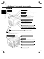
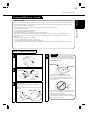
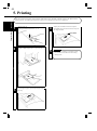
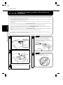
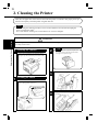
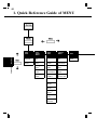
1
0990-7701-02 Color PageWorks User's Manual Copyright 1997 MINOLTA CO., LTD Printed in Japan The information contained in this manual is subject to change without notice to incorporate improvements made on the product or products the manual covers. MINOLTA CO., LTD 3-13, 2-chome, Azuchi-machi, Chuo-ku, Osaka, 541, Japan 7. 8 i Color PageWorks This manual explains the functions and operation of the MINOLTA Color PageWorks printer. It also gives some troubleshooting tips as well as general precautions to be observed when operating this printer. To ensure the best performance and effective use of your printer, please read this manual carefully from cover to cover. After you have read through the manual, keep it near your printer for handy reference. It should help in solving any operational questions you may have. Trademark acknowledgments Color PageWorks is a trademark of Minolta in the U.S. and Canada. Minolta is a registered trademark of MINOLTA CO., LTD. Adobe and PostScript are trademarks of Adobe Systems Incorporated. Agfa and Agfa Intelifont, Agfa font Manager are registered trademarks of Agfa Corporation. Apple, AppleTalk, ColorSync, Macintosh and TrueType are registered trademarks of Apple Computer Inc. HP, LaserJet and PCL are registered trademarks of Hewlett-Packard Company. IBM, PC/ AT and PS/ 2 are registered trademarks of International Business Machines Corporation. Microsoft, MS-DOS, Excel, Windows 3.1, Windows NT and Windows 95 are registered trademarks of Microsoft Corporation. Novell, NetWare, and NDS are registered trademarks of Novell Inc. All other brand or product names are trademarks or registered trademarks of their respective companies or organizations. 7701 Please follow the instructions given in this manual when handling your printer and do not touch any part of the machine which the manual does not cover. NEVER attempt to disassemble or remodel the printer. ii Safety Information LASER SAFETY This is a page printer which operates by means of a laser. There is no possibility of danger from the laser, provided the printer is operated according to the instructions in this manual provided. Since radiation emitted by the laser is completely confined within protective housing, the laser beam cannot escape from the machine during any phase of user operation. INTERNAL LASER RADIATION (For all Users) Maximum Radiation power: 1.0 ✕ 10 -3 (W) Wavelength: 770- 810 (nm) This is a class IIIb Laser Diode Assy. that has an invisible laser beam. The printer head unit is NOT A FIELD SERVICE ITEM. Therefore, the printer head unit should not be opened under any circumstances. For United States Users Laser Safety This printer is certified as a Class 1 Laser product under the U. S. Department of Health and Human services (DHHS) Radiation Performance Standard according to the Food, Drug and Cosmetic Act of 1990. This means that the printer does not produce hazardous laser radiation. CDRH Regulations The Center for Devices and Radiological Health (CDRH) of the U. S. food and Drug Administration implemented regulations for laser products on August 2, 1976. Compliance is mandatory for products marketed in the United States. The label shown below indicates compliance with the CDRH regulations and must be attached to laser products marketed in the United States. WARNING: Use of controls, adjustments or performance of procedures other than those specified in this manual may result in hazardous radiation exposure. For Other Countries Users WARNING: Use of controls, adjustments or performance of procedures other than those specified in this manual may result in hazardous radiation exposure. This is a semiconductor laser. The maximum power of the laser diode is 1.0✕ 10 -3 W and the wavelength is 770- 810 nm. 7701 iii Safety Information USER INSTRUCTIONS (FOR U.S.A. Users) FCC PART 15- RADIO FREQUENCY DEVICES WARNING (Note: Color PageWorks printer without Minolta Network option installed.) WARNING This equipment has been tested and found to comply with the limits for a Class B digital device, pursuant to Part 15 of the FCC Rules. These limits are designed to provide reasonable protection against harmful interference in a residential installation. This equipment generates, uses, and can radiate radio frequency energy and, if not installed and used in accordance with the instructions, may cause harmful interference to radio communications. However, there is no guarantee that interference will not occur in a particular installation. If this equipment does cause harmful interference to radio or television reception, which can be determined by one or more of the following measures: • Reorient or relocate the receiving antenna. • Increase the separation between the equipment and the receiver. • Connect the equipment to an outlet on a circuit different from that to which the receiver is connected. • Consult the dealer or an experienced radio/ TV technician for help. • Any changes or modifications not expressly approved by Minolta could void the user’s authority to operate this equipment. A LAN adapter is only to be used in industrial areas including commercial areas. Use of a LAN adapter in residential areas is forbidden. This device must be used with shielded interface cables. The use of non-shielded cables is likely to result in interference with radio communications and is prohibited under FCC rules. The design and production of this unit conform to FCC regulations, and any changes or modifications must be registered with the FCC and are subject to FCC control. Any changes made by the purchaser or user without first contacting the manufacturer will be subject to penalty under FCC regulations. FCC PART 15- RADIO FREQUENCY DEVICES WARNING (Note: When the network cable is attached to either of the IEEE 802.3 connectors the printer meets the requirement of FCC Class A, Color PageWorks printer with Minolta Network option installed.) WARNING This equipment has been tested and found to comply with the limits for a Class A digital device, pursuant to Part 15 of the FCC Rules. These limits are designed to provide reasonable protection against harmful interference when the equipment is operated in a commercial environment. This equipment generates, uses and can radiate radio frequency energy and, if not installed and used in accordance with the instruction manual, may cause harmful interference to radio communications. Operation of this equipment in a residential area is likely to cause harmful interference in which case the user will be required to correct the interference at his own expense. This device must be used with shielded interface cables. The use of non-shielded cables is likely to result in interference with radio communications and is prohibited under the FCC rules. The design and production of this unit conform to FCC regulations, and any changes or modifications must be registered with the FCC and are subject to FCC control. Any changes made by the purchaser or user without first contacting the manufacturer will be subject to penalty under FCC regulations. 7701 iv Safety Information USER INSTRUCTIONS (FOR Canadian Users) INTERFERENCE-CAUSING EQUIPMENT STANDARD (ICES-003 ISSUE 2) WARNING (Note: Color PageWorks printer without Minolta Network option installed.) This Class B digital apparatus meets all requirements of the Canadian Interference-Causing Equipment Regulations. Cet appil numérique de la class B respecte toutes les exigences du Règlement sur le matériel brouilleur du Canada. INTERFERENCE-CAUSING EQUIPMENT STANDARD (ICES-003 ISSUE 2) WARNING (Note: Color PageWorks printer with Minolta Network option install.) This Class A digital apparatus meets all requirements of the Canadian Interference-Causing Equipment Regulations. Cet appil numérique de la class A respecte toutes les exigences du Règlement sur le matériel brouilleur du Canada. OZONE RELEASE (For all Users) During printer operation, a small quantity of ozone is released. This amount is not large enough to harm anyone adversely. However, be sure the room where the printer is being used has adequate ventilation, especially if you are printing a high volume of materials, or if the printer is being used continuously over a long period. WARNING LABEL 7701 v Highlight 2. Adobe PostScript Level 2 1. High quality printing • Option • Clear text and excellent graphics with true 600 dpi. • Excellent graphics (106 lpi, 122gray levels) • Super Fine Micro Toning (Fine-MT) developing system. • 8µm small particle toner. • Color matching technology. - Apple ColorSync (is available only when the optional Adobe PostScript ROMSIMM is installed). - Windows95 ICM. - Printer embedded color matching. 3. High speed printing • Full color 3ppm, B/W 12ppm. • High performance RISC processor. - Intel i960JF/ 33MHZ. • High speed data transfer. - IEEE 1284 compliant interface. - Network option (Ethernet/ TokenRing). 4. Paper handling versatility 5. Compact size • OHP, labels, thick paper, envelopes. • Width 505mm/ 20" • Depth 527mm/ 20-3/4” • Height 403mm/ 15-3/4” 6. Network ready with option • Ethernet / TokenRing Server: UNIX, Windows NT, NetWare 3.X/ 4.X (Bindery & NDS) Client: Windows 95/ 3.1, Macintosh (option) 7. Easy maintenance and operation • Easy maintenance with cartridge type consumables. • GUI driver. 8. Environmentally friendly • Ozone free. • Power save mode (Energy Star compliant). 7701 vi Using This Manual Organization This manual consists of 6 chapters. Chapters 1 and 2 give the basic information about the printer, chapter 3 introduces the menu utilities of the printer operation, chapter 4 through 6 cover maintenance of the printer and some troubleshooting tips. Please read chapter 1 and 2 before attempting to use your printer. Reading these chapters will help you understand the installation and basic operation of your printer. Read chapter 3 as necessary when you want to use the more advanced menus the machine offers. Chapters 4 and 5 are to be read when you need to add paper, service or troubleshoot the printer. An explanation is given of each operation, allowing you to read only those pages dealing with the operation to be performed. Chapter 6 contains a quick reference overview of the menu utilities setting procedure, specifications, and index. Locating the Information You Need Using the Master Table of Contents The master table of contents gives an overview of how this manual is organized so that you can quickly locate the information you need. It provides you with the most basic keys for locating what you need to know. Using the Contents at the Beginning of Each Chapter The first page of each chapter contains a table of contents which provides greater detail than the Master Table of Contents. This provides a quick reference for each chapter. Using the Index At the back of the book is an alphabetical index which is function-, item-, or term-oriented; i.e., if you know the name of a particular function, item or term, use this section to find a reference to the appropriate page number. If You Need More Information (U.S.A. Technical Support) If you continue to experience technical difficulty with the operation of your printer product, please contact your support representative: Toll free at 1-800-459-3250 or via our website at http://www.minoltappd.com. Hours of operation and toll free nature of our support program is subject to change without prior notice. 7701 vii Page Layout Operational Heading Before operation: Gives an overview of the function/ operation covered herein. Page Number: Used to locate your page. Note: Calls your attention to a particular point in the procedure. Continuation marker: Indicates that there is more information to complete an operation on the next page. Index: Used to locate your chapter quickly. Step No.: Sequential number to follow in performing the procedure. 7701 viii CONTENTS Energy Star Information Introduction i Safety Information ii Highlight v Using This Manual vi Contents viii Chapter 1 Installation 1 1. Preparation for Installation 2 Installation Site/ Power Source/ Grounding 2 Space Requirements 3 2. Precautions for Use 4 Operating Environment/ Using the Printer Properly 4 Care of Printer Supplies/ Moving the Printer 5 3. Setting-Up 6 Checking print operation 6 Connecting Printer to Host Computer 8 Expansion Memory (option) Setting-Up 10 Adobe PostScript ROM SIMM (option) Setting-Up 12 Network Board (option) Setting-Up 14 Chapter 2 Using the Printer 17 1. Printer Parts and Accessories 28 ⋅ Printer 18 ⋅ Accessories 19 ⋅ Control Panel keys 20 ⋅ Operation and warning Labels 22 2. Turning ON and OFF the Printer 23 3. Printing Paper 24 ⋅ Type/ Size 24 ⋅ Print Area/ Capacity/ Care of paper 25 4. Loading the Printing Paper 26 ⋅ Loading Plain Paper/ Recycled Paper 26 - TRAY 1 (Multi Purpose Tray) 26 - TRAY 2 (Second Cassette)/ TRAY 3 (Third Cassette: option) 27 ⋅ Loading OHP sheets/ Labels 29 - TRAY 1 (Multi Purpose Tray) 29 - TRAY 2 (Second Cassette)/ TRAY 3 (Third Cassette: option) 30 ⋅ Loading Special Paper (Letterhead/ Envelopes/ Postcard/ Thick Paper) 32 - TRAY 1 (Multi Purpose Tray) 32 5. Printing 34 7701 ix CONTENTS CHAPTER 1 Chapter 3 Changing the Printer Settings 45 Installation 1. List of MENU Utilities 36 2. Setting the MENU Utilities 38 3. Outline of the MENU Utilities 40 Using the Printer ⋅ RESET MENU/ TEST PRINT MENU 40 ⋅ PRINT MENU 41 ⋅ CONFIG MENU 42 ⋅ IMAGE MENU/ MEMORY MENU 43 ⋅ PCL MENU 44 ⋅ PS MENU / MAINTENANCE MENU 45 Chapter 4 Maintaining Your Printer 47 1. Changing Cartridges 48 ⋅ Changing the Toner Cartridge 48 Auto Mode 48 Manual Mode 52 ⋅ Changing the Drum Cartridge, Toner Collecting Bottle and Oil Roller Unit 56 ⋅ Changing the Fusing Unit and Transfer Roller Unit 62 ⋅ Changing the Image Transfer Belt Unit 66 2. Cleaning the Printer 70 CHAPTER 2 CHAPTER 3 Changing the Printer Settings CHAPTER 4 Maintaining Your Printer CHAPTER 5 Trouble shooting CHAPTER 6 Appendices Chapter 5 Troubleshooting 73 1. How to Troubleshooting 74 2. A Problem Exists in the preparation stage and during a Print Cycle 75 − A Problem Exists in Preparation Stage 75 − A Problem Occurs When You Attempt to Start a Print Cycle 75 − When a Message Appears 76 − When a Paper Misfeed has Occurred 80 3. Print Results are Faulty 84 Chapter 6 Appendices 87 1. Quick Reference Guide of MENU 88 2. List of MENU Utilities 90 3. Specifications of Printer 92 4. Specifications of 250 sheet Third Cassette Unit 95 5. Index 96 7701 7701 x 7701 For U.S.A./ Canada Users As an ENERGY STAR Partner, MINOLTA Co., Ltd has determined that this printer meets the ENERGY STAR Guidelines for energy efficiency. For Other Country Users This printer meets the *EPA’s ENERGY STAR Guidelines for energy efficiency. *The U. S. Environmental Protection Agency. What is an Energy Star Printer? Energy Star Printers have a feature that allows them to automatically “go to sleep” after a period of inactivity. This auto-feature can reduce a machine’s annual electricity cost by 60 percent. 7701 Installation This chapter covers site preparation, precautions for use, and set-up procedure. 1. Preparation for Installation 2 Installation Site 2 Power Source 2 Grounding 2 Space Requirements 3 2. Precautions for Use 4 Operating Environment 4 Using the Printer Properly 4 Care of Printer Supplies 5 Moving the Printer 5 3. Setting-Up 6 Checking print operation 6 Connecting Printer to Host Computer 8 Expansion Memory (option) Setting-Up 10 Adobe PostScript ROM SIMM (option) Setting-Up 12 Network Board (option) Setting-Up 14 Installation Chapter 1 CHAPTER 1 1 Installation CHAPTER 1 2 1. Preparation for Installation Installation Site To ensure a longer life for the printer, it is highly important to select an appropriate installation site. Choose a site that meets the following requirements. - A well-ventilated place. - An area which will not generate ammonia or other organic gas. - A place which is near a power outlet so that the power cord can be easily plugged in and unplugged. - An area free from direct sunlight. - A place which is out of the direct air stream of an air conditioner, heater, or ventilator and is not subject to extremely high or low temperature or humidity. - A stable and level location not subject to undue vibration. - A place free from an object that could block the heat exhaust duct of the printer. - A place away from a curtain or the like that may catch fire and burn easily. - An area where there is no possibility of being splashed with water or other types of liquid. - A dust-free location. Power Source The power source voltage requirements are as follows. - Power source: voltage fluctuation within +10% to -10% - Frequency fluctuation: within +3Hz to -3Hz NOTES NOTE - Use a power source with little voltage and frequency fluctuation. - Use an outlet with the specified voltage capacity only. - Be sure to plug the power cord all the way into the outlet. The outlet should also be located near the printer and easily accessible so that the power cord can be unplugged immediately if printer trouble occurs. - Make sure that the outlet is visible, without being hidden behind this printer or any other office equipment. - If any other electrical equipment is sourced from the same outlet, make sure that the capacity of the outlet is not exceeded. - If an extension cord is needed, use one with a capacity greater than the power consumption of the printer. A cord which falls short of the capacity requirements could lead to a fire. - Never connect any other appliances or machines by means of a multiple socket to the outlet being used for the printer. Grounding To prevent receiving electrical shocks in the case of electrical leakage, always ground the printer. Consult your Technical Representative if you are unable to make grounding connections. Connect the grounding wire to: - The ground terminal of the outlet. - A grounding contact which complies with the local electrical standards. *NEVER connect the grounding wire to a gas pipe, the grounding wire for a telephone, or a water pipe. Space Requirements You must provide open space on all sides of the Printer. Allow at least 300mm (11-3/4 inch) of space above the printer as well, so that you can open the printer cover to replace supplies and clear paper misfits. You also will need easy access to the rear of the printer to connect the printer cable and clear paper misfits. 300mm (11-3/4 inch) 300mm (11-3/4 inch) 100mm (4 inch) 1,380mm (54-1/4 inch) 550mm (21-3/4 inch) 905mm (35-3/4 inch) Installation 1. Preparation for Installation CHAPTER 1 3 Installation CHAPTER 1 4 2. Precautions for Use Operating Environment The operating environmental requirements of the printer are as follows. - Temperature: 10°C (50°F) to 35°C (86°F) with a fluctuation of 10°C (50°F) per hour. - Humidity: 15% to 85% RH with a fluctuation of 20% per hour. * The environmental zone marked “X” on the right represents a critical environment in which the printer can be left to stand. However the manufacturer does not ensure good paper passage performance and print image in this zone. Be sure to use the printer within the operating environment marked by the bold line. Humidity (%) X Temperature (°C) Using the Printer Properly X To ensure the optimum performance of the printer, follow the precautions listed below. : Outside guarantee of paper passage and image reliability - NEVER open any door, or turn OFF the printer during operation. - NEVER bring any magnetized object or flammable gas or liquid near the printer. - NEVER pull on the cord and ALWAYS hold the plug when unplugging the power cord. A damaged cord could result in a fire or cause an electrical shock. - NEVER attempt to unplug the power cord with a wet hand, as it could cause an electrical shock. - ALWAYS unplug the power cord whenever attempting to move the printer. Moving the printer with the power cord plugged in can damage the cord, resulting in a fire or causing an electrical shock. - ALWAYS unplug the power cord when the printer is not to be used for a long time. - NEVER remove any panel or cover which is secured. The printer contains a high-voltage component inside which can cause an electrical shock. - NEVER remodel the printer, as a fire or electrical shock could result. - NEVER place a heavy object on the power cord, or pull or bend it, as a fire or electrical shock could result. - ALWAYS ensure that the printer does not ride on the power cord or communications cable of other electrical equipment, and it does not get such a cord or cable wedged into its own mechanism, as malfunctioning equipment or fire could result. - NEVER drop paper clips, staples, or other small pieces of metal through the vents or other openings in the printer, as a fire or electrical shock could result. - NEVER place a vase or vessel containing water on the printer. If fluid gets inside, it can cause a fire or electrical shock. In case a piece of metal or fluid gets inside the printer, immediately turn it OFF, unplug the power cord, and call your technical representative. A fire or electrical shock could result if the printer is run without taking necessary action. - NEVER leave the printer running when it becomes inordinately hot, or emits smoke, unusual smell, or noise. If that happens, immediately turn OFF the printer, unplug it, and call your technical representative. A fire or electrical shock could result if the printer is run without taking necessary action. NOTE NOTE = Locate the printer in a Well Ventilated Room = A negligible amount of ozone is generated during normal operation of this printer. An unpleasant odor may, however, be created in poorly ventilated rooms during extensive printer operations. For a comfortable, healthy, and safe operating environment, it is recommended that the room be well ventilated. REMARQUE REMARQUE = Placer le imprimante dans une pièce largement ventilée = Unequantité d’ ozone négligable est dégagée pendant le fonctionnement du imprimante quand celui-ci est utilisé normalement. Cependant, use odeur désagréable pent être ressentie dans les pièces dont l’ aération est insuffisante et lorsque une utilisation prolongée du imprimante est effectuée. Pour avoir la certitude de travailler dans un environnement das conditions de confort, anté et sécurité, il est préférable de bien aérer la pièce ou se trouve le imprimante. Care of Printer Supplies Use the following precautions when handling the printer supplies (Toner Cartridge, Drum Cartridge, and paper). - Avoid storing the supplies at any of the following places: A place subject to direct sunlight. (The Drum Cartridge should not be exposed to fluorescent light, either.) A hot place with an open flame. A humid place. A dusty place. - Store paper, which has been removed from its wrapper but not loaded in the printer tray, in a sealed plastic bag in a cool, dark place. - Use only the Toner Cartridge and toner for the exclusive use of this printer. - Keep supplies out of the reach of children. - If your hands become soiled with toner, wash them with soap and water immediately. NOTE NOTE Whenever the Drum Cartridge has been removed from the printer, immediately wrap it in a cloth to protect it from light. Moving the Printer Observe the following precautions when moving the printer. - When the Third Cassette Unit is installed, remove it from the printer and carry the printer. - Since the printer weighs approximately 35kg (77-1/4 lbs.), two people are required to lift it. - If you need to transport the printer over a long distance, consult your Technical Representative. Grips Installation 2. Preparation for Installation CHAPTER 1 5 3. Setting-Up - The following four different procedures must be performed to set up the printer. Perform them step by step. 1. Hardware Setting-Up (Printer and 250-Sheet Third Cassette Unit) ☞Unpacking/ Setting-Up Instructions*1 2. Checking Print Operation ☞p. 6 3. Connecting Printer to Host Computer ☞p. 8 4. Software Setting-Up ☞Printer Driver User's Manual*2 Installation CHAPTER 1 6 NOTE: *1Read the Unpacking/ Setting-Up Instructions (that is shipped together with the accessories that come with this printer set and the 250-Sheet Third Cassette Unit). *2Read the Printer Driver User's Manual separately provided (that is shipped together with the accessories that come with this printer set) and install the printer driver according to the operating system of the host computer to be used. - When the optional Network Board, Expansion Memory, and/or Adobe PostScript ROM SIMM are to be used, perform the steps according to the setting-up procedure for each option. : Expansion Memory ☞p. 10 : Adobe PostScript ROM SIMM ☞p. 12 : Network Board ☞p. 14 - For the parts that come with the Printer and Third Cassette Unit see the UNPACKING/ SETTING-UP INSTRUCTIONS. CAUTION - ALWAYS use a shielded cable for the interface cable. Use of an unshielded interface cable could result in radio frequency interference. - Keep all packing materials out of the reach of children. They are to be used when transporting the printer. CHECKING PRINT OPERATION 2 1 - Make sure that the “Hardware Setting-Up” procedure has been completed ☞ the Unpacking/ Setting-Up Instructions. 3 - Open the Multi-Purpose Tray. - Adjust the Paper Guides to fit the size of the Paper. - Load the paper stack on the tray facing up. Face up Multi-Purpose Tray 2 2 - Ready several sheets of paper for test prints. Use plain paper of A4 or Letter size, weighing 60 g/m2 (16 lbs.) to 90 g/m2 (24 lbs.). - Open the wrapper of the paper. - Fan the paper stack thoroughly and align its edges. 4 - Check that “READY” is shown on the Message Display. READY READY Paper Face 5 - Press the On Line key on the control panel. - Check that “OFF LINE” appears on the Message Display. - Check that the On Line Indicator goes out. 9 - Check that the data on the following demonstration page is printed. Typical Printout: ✕ Once OFFLINE 6 - Press the Menu key on the control panel twice. - Check that “TEST PRINT MENU” appears on the Message Display. ✕ Twice - If the printer turns out blank sheets of paper TEST PRINT MENU 7 without printing the data, the “Hardware Setting “was not probably done properly. In this case, turn the Power Switch OFF and perform the “Hardware Setting-Up (Unpacking/ Setting-Up Instructions)” procedure. If the data on the demonstration screen is still not printed, contact your Technical Representative. - Press the Item key on the control panel once. - Check that “PRINT CONFIG” appears on the Message Display. ✕ Once PRINT CONFIG ENTER TO PRINT 8 - Press the Enter key on the control panel. - The Data Indicator on the control panel lights up. 10 - Press the On Line key on the control panel . ✕ Once - Check that “READY” appears on the Message Display. - Make sure that the On Line Indicator lights up. READY - This completes the checking procedure for the printing operation. - Let's then connect the printer to the host computer. ☞p. 8 Installation 3. Setting-Up CHAPTER 1 7 3. Setting-Up Connecting Printer to Host Computer Installation CHAPTER 1 8 PRECAUTION - This printer is equipped with the following two types of interface connectors for connection to the host computer. Select the correct interface to suit the host computer to be used. Parallel interface - Connector type: IEEE 1284 36-pin Amphenol (full) - Typical compatible computer models: IBM PC/AT or compatible (OS: Windows 3.1/3.11/95) Serial interface - Connector type: LocalTalk DIN-8 (only can use with optional PostScript SIMM) - Typical compatible computer models: Apple Macintosh series (OS: System Level 7 or higher) - The type of interface cable used for connecting the printer to the host computer varies depending on the type of computer used. (This printer set does not contain an interface cable.) Study the operator's manual of your computer and purchase the correct interface cable applicable to this printer and computer. CAUTION - ALWAYS use a shielded cable for the interface cable. Use of an unshielded interface cable could result in radio frequency interference. 1 - Make sure that the “Hardware Setting-Up ☞the Unpacking/ Setting-Up Instructions and “Checking Print Operation” ☞p. 6 procedures have been completed. - Turn the printer OFF. Power Switch 2 For Parallel Interface - Connect one end of the interface cable to the parallel port of the host computer. - Connect the other end of the interface cable to the interface connector on the back side of the printer. - Secure the plug by closing the two clips provided. Parallel Interface connector Interface cable - Check that the host computer to be connected to the printer is OFF. 3 For Serial Interface - Connect one end of the interface cable to the serial port of the host computer. - Connect the other end of the interface cable to the interface connector on the back side of the printer. Serial Interface connector Interface cable 4 - This completes the connection of the printer to the host computer. - You next install the printer driver (software). Read the Printer Driver User’s Manual separately provided (that is shipped together with the accessories that come with this printer set) and install the printer driver according to the operating system of the host computer to be used. Installation 3. Setting-Up CHAPTER 1 9 3. Setting-Up Expansion Memory (Option) Setting-Up Installation CHAPTER 1 10 PRECAUTION - This printer is equipped with two sockets for the installation of expansion memory. - The optional expansion memories come in five different capacities: 1 MB, 2 MB, 4 MB, 8MB, 16 MB, and 32 MB. The combination in which expansion memories of different capacities are plugged in allows the memory capacity of the printer to be expanded up to 68 MB (standard 4 MB + expansion 64 MB). Purchase the expansion memory according to your particular need. CAUTION - Before opening the optional packages or handling the options, briefly touch the metal part of the printer to remove any electrostatic charge from your body. - When options are taken out of their conductive bags or off their mats, hold them by their edge to avoid touching the terminals or the patterned surfaces. - When the Controller board is taken out of the printer, hold it by the edges to avoid touching the terminals or the patterned surfaces. - After removing the options or Controller board, be sure to place it on an anti-static mat or a piece of aluminum foil. 1 - Turn the printer OFF. 3 - Remove the four screws that secure the controller board on the back of the printer. - Slide out the controller board. Power Switch 2 - Disconnect the cable from the interface connector (Parallel or Serial) or network connector (10BASE-T or 10BASE-2) on the back of the printer. 4 NOTE - When the Controller board is taken out of the printer, hold it by the edges to avoid touching the terminals or the patterned surfaces. - After removing the options or Controller board, be sure to place it on an anti-static mat or a piece of aluminum foil. in your printer. - Mount the expansion memory in the socket (SIMM3 or 4) at the location shown on the controller board. SIMM3 9 CHAPTER 1 5 - Take the Expansion Memory out of its carton. - Check which type of Controller board is installed 3. Setting-Up -Insert the controller board into the guide rails. - Secure the controller board in position with the Installation 11 four screws. SIMM4 Controller board (a) SIMM3 SIMM4 Controller board (b) 6 - Insert the expansion memory pin into the socket. 10 7 8 - Reconnect the interface cable or network cable. - Push the expansion memory down in the direction of the arrow. - Check that the expansion memory is mounted securely. Left Side Right Side 11 - This completes the procedure to mount the expansion memory in the printer. - You now change the setting for <Installed memory> that is one of the setup items of the printer driver on the host computer. For details, see the Printer Driver Operator's Manual separately provided (that is shipped together with the accessories that come with this printer set). 3. Setting-Up Adobe PostScript ROM SIMM (Option) Setting-Up Installation CHAPTER 1 12 PRECAUTION - This printer is equipped with a socket for the installation of an Adobe PostScript ROM SIMM. When the printer is equipped with an Adobe PostScript ROM SIMM, it can function as a PostScript printer. CAUTION - Before opening the optional packages or handling the options, briefly touch the metal part of the printer to remove any electrostatic charge from your body. - When options are taken out of their conductive bags or off their mats, hold them by their edges to avoid touching the terminals or the patterned surfaces. - When the Controller board is taken out of the printer, hold it by the edges to avoid touching the terminals or the patterned surfaces. - After removing the options or Controller board, be sure to place it on an anti-static mat or a piece of aluminum foil. 1 - Turn the printer OFF. 3 - Remove the four screws that secure the controller board on the back of the printer. - Slide out the controller board. Power Switch 2 - Disconnect the cable from the interface connector (Parallel or Serial) or network connector (10BASE-T or 10BASE-2) on the back of the printer. 4 NOTE - When the Controller board is taken out of the printer, hold it by the edges to avoid touching the terminals or the patterned surfaces. - After removing the options or Controller board, be sure to place it on an anti-static mat or a piece of aluminum foil. in your printer. - Mount the PostScript ROM in the socket (SIMM2) at the location shown on the controller board. SIMM2 9 CHAPTER 1 5 - Take the PostScript ROM out of its carton. - Check which type of Controller board is installed 3. Setting-Up - Insert the controller board into the guide rails. - Secure the controller board in position with the Installation 13 four screws. Controller board (a) SIMM2 Controller board (b) 6 - Insert the PostScript ROM pin into the socket. 10 7 8 - Reconnect the interface cable or network cable. -Push the PostScript ROM down in the direction of the arrow. - Check that the PostScript ROM is mounted securely. Left Side Right Side completes the procedure to mount the 11 - This PostScript ROM in the printer. - You now install the printer driver (software). Read the PostScript User’s Guide separately provided (that is shipped together with the accessories that come with this Adobe PostScript ROMM SIMM set) and install the printer driver according to the operating system of the host computer to be used. 3. Setting-Up Network Board (Option) Setting-Up Installation CHAPTER 1 14 PRECAUTION - The network board is equipped with the following two types of interface connectors for connection to the network server. Select the correct interface to suit the network to be used. 10BASE-T 10BASE-2 3. Setting-Up Expansion Memory Setting- - The type of cable used for connecting the printer to the network server varies depending on the connection method of the network to be used. (The accessories that come with the network board do not contain a cable.) Study the operator's manual of your network and purchase the correct cable applicable to the connection between the CAUTION printer and network server. CAUTION - Do not make connections both to 10BASE-T and 10BASE-2 at the same time, because it will deactivate the automatic detection function of the connector connected, disabling communications. - Before opening the optional packages or handling the options, briefly touch the metal part of the printer to remove any electrostatic charge from your body. - When options are taken out of their conductive bags or off their mats, hold them by their edges to avoid touching the terminals or the patterned surfaces. - When Controller board is taken out of the printer, hold it by the edges to avoid touching the terminals or the patterned surfaces. - After removing the options or Controller board, be sure to place it on an anti-static mat or a piece of aluminum foil. 1 2 - Turn the printer OFF. Power Switch - Remove the two screws that secure the network board panel on the back of the printer. - Remove the network board panel. 3 4 NOTE - When the Network Board is taken out of its conductive bag or off its mat, hold the Network Board by the edges to avoid touching the terminals or the patterned surfaces. - Take the Network Board out of its carton. 5 - Insert the network board into the mounting rails. 6 - This completes the procedure to mount the - Tighten the two screws that secure the network board in position. network board in the printer. - Now, read the Network Printer Operator's Manual separately provided (that is shipped together with the accessories that come with the Network Board set), connect the network cable and set the network environment variable through the host computer. Installation CHAPTER 1 15 Installation CHAPTER 1 16 3. Setting-Up 17 Chapter 2 This chapter gives basic information on the different parts of the printer and shows you how to use the printer. 1. Printer Parts and Accessories 18 ⋅ Printer 18 ⋅ Accessories 19 ⋅ Control Panel keys 20 ⋅ Operation and Warning Labels 22 2. Turning ON and OFF the Printer 23 3. Printing Paper 24 ⋅ Type 24 ⋅ Size 24 ⋅ Capacity 24 ⋅ Print Area 25 ⋅ Care of paper 25 4. Loading the Printing Paper 26 ⋅ Loading Plain Paper/ Recycled Paper 26 - TRAY 1 (Multi Purpose Tray) 26 - TRAY 2 (Second Cassette)/ TRAY 3 (Third Cassette: option) 27 ⋅ Loading OHP sheets/ Labels 29 - TRAY 1 (Multi Purpose Tray) 29 - TRAY 2 (Second Cassette)/ TRAY 3 (Third Cassette: option) 30 ⋅ Loading Special Paper (Letterhead/ Envelopes/ Postcard/ Thick Paper) 32 - TRAY 1 (Multi Purpose Tray) 32 5. Printing 34 Using the Printer Installation CHAPTER 2 Using the Printer 18 1. Printer Parts and Accessories Power Switch Print Tray The printed paper is fed out face down onto this tray. The tray can hold 250 sheets of printed paper. ☞p. 34 Using the Printer CHAPTER 2 PRINTER Use to turn the printer ON and OFF ☞p. 23 Front Cover Swing open to change supplies such as the Toner Cartridge or to clear a paper misfeed. Control Panel -Allows the operator to make various settings. -The LCD Display shows the current status of the printer. For more details, see “Control Panel Keys.” ☞p. 20 Front Cover Lock Release Lever Pull down to unlock the Front Cover. TRAY 1 (Multi Purpose Tray) - Swing open toward you to load paper. - Holds up to 150 sheets of paper. ☞p. 24 TRAY Œ 2 (250-Sheet Second Cassette) Holds up to 250 sheets of paper. ☞p. 24 TRAY 3 (250-Sheet Third Cassette: Option) Holds up to 250 sheets of paper. ☞p. 24 250-Sheet Third Cassette Unit (Option) When installed under the Printer, houses a third cassette increasing paper capacity to 650 sheets. Grips - Two grips are provided on each side of the printer (four in all). Used to hold the printer when installing or moving it. - The printer should be lifted by two persons. ☞p. 5 Network Board Panel -Use to mount the optional network board. ☞p. 14 Rear Cover Lock Release Lever Pull down to swing open the Rear Cover. Rear Cover Swing open to change the Oil Roller Assembly or clear a paper misfeed. Interface Connector (Serial Connector) Provides connection between the printer and host computer. ☞p. 8 Interface Connector (Parallel Connector) Provides connection between the printer and host computer. ☞p. 8 Power Cord Socket Connect the power cord of the printer to this socket. 19 1. Printer Parts and Accessories Toner Cartridge Waste bottle - Used to collect and contain waste toner. - Replace this Bottle with a new one when it is filled with waste toner. - Put the old bottle in a polyethylene bag or the like and dispose of it according to your local regulations. ☞p. 56 - There are four different color Toner Cartridges: Black, Yellow, Magenta and Cyan. - Replace this cartridge with a new one when it runs out of toner. - Put the old Cartridge in a polyethylene bag or the like and dispose of it according to your local regulations. ☞p. 52 Image Transfer Belt Unit - Transfers the image created by the Drum Cartridge onto paper. Handle with utmost care. ☞p. 66 Drum Cartridge - The image is formed on it. Handle with utmost care. - Replace this Cartridge with a new one when it reaches the time to change. - Put the old Cartridge in a polyethylene bag or the like and dispose of it according to your local regulations. ☞p. 56 Image Transfer Roller Unit Transfers the image created by the Drum Cartridge onto paper. Handle with utmost care. ☞p. 62 Oiling Roller - Supplies the Fusing Rollers with oil and cleans them off. - Replace this Roller with a new one when it reaches the time to change. - Put the old Roller in a polyethylene bag or the like and dispose of it according to your local regulations. ☞p. 56 Fusing Unit Permanently fixes the image onto paper. ☞p. 62 Using the Printer Installation CHAPTER 2 ACCESSORIES 20 1. Printer Parts and Accessories Using the Printer CHAPTER 2 CONTROL PANEL KEYS Message Display - Shows the message telling the current status Data Indicator of the printer. - Shows the setting made for the various functions. - Data Indicator ON When data received from the host computer is stored in the printer memory. - Data Indicator OFF When no data is stored in the printer memory, usually immediately after power on or reset. - Data Indicator Flashing When the printer is receiving data from the host computer. Message Indicator - Message Indicator Flashing When the printer is asking the user for something to occur or when an error occurs. - Message Indicator OFF Otherwise. Œ On Line Key ☞p. 38 The One Line key changes the state between on-line and off-line. If the key is pressed while in the Menu mode, the printer exits the menu and returns on-line. All keys except this key are valid during the off-line state. On-line Indicator ☞p. 38 - On-line Indicator ON When the printer can receive data from the host computer. - On-line Indicator Flashing During Power On Self Test and initialization. - On-line Indicator OFF When the printer can’t receive data from the host computer. Proceed key The Proceed key clears most recoverable errors and returns the printer back to On-line. The key overrides manual feed and paper size requests. 21 1. Printer Parts and Accessories Menu Key ☞p. 38 Item Key Accesses the list of items after selecting a Menu and selects the menu item. This key must be pressed when Menu is selected otherwise no action takes place while displaying “Off Line”. The items go through a loop until the On Line key is pressed or the Menu key is pressed. When the On Line key is pressed, the printer returns to On Line and when the Menu key is pressed, the next Menu selection is displayed. ☞p. 38 UP & DOWN Keys These two keys display the next or the previous setting for the current menu item. If the UP or Down key is pressed continuously when one of the following items are on the LCD, (FONT NUMBER, and PT SIZE), the value is incremented / decremented faster. Enter Key ☞p. 38 This key saves the menu settings while in the Item menu mode. An asterisk appears at the right of the LCD to indicate the current menu setting. Pressing the Enter key in the TEST PRINT MENU, the printer executes the appropriate TEST PRINT MENU including PRINT CONFIG, PCL FONT LIST, PCL DEMO PAGE and PS DEMO PAGE. Using the Printer Installation CHAPTER 2 Accesses the print and configuration menus. The menus goes through a loop until the On Line key is pressed. 22 1. Printer Parts and Accessories Using the Printer CHAPTER 2 OPERATION AND WARNING LABELS Installing the Toner Cartridge - Describes how to replace the Toner Cartridge when it runs out of toner. For details of operation, refer to “Changing the Toner Cartridge” on page 48. Changing the Waste bottle, Drum Cartridge and Oiling Roller - Describes how to replace the Waste bottle, Drum Cartridge and Oiling Roller. For details of operation, refer to “Changing the Drum Cartridge, Waste bottle and Oiling Roller” on page 46. - The Waste bottle, Drum Cartridge and Oiling Roller are preset to reach the time to change simultaneously. Replace these three Units at the same time. Œ Clearing Paper Misfeed in Paper Path - Describes how to remove paper using the Misfeed Removal Cover and Roller Lock Release Lever if a paper misfeed occurs in the paper path. - For details of operation, refer to “When a Paper Misfeed has Occurred” on page 78. Loading Paper - Describes how to replenish the Paper Feeding Tray with paper. - For details of operation, refer to “Loading the Printing Paper” on page 26. WARNING! HIGH TEMPERATURE - Alerts you to the high temperature of the area where the label is applied on the Fusing Unit. Do not touch this area when you change the Oiling Roller or clear a misfeed. 23 Turning Printer Printer ON ON Turning Press the Power Switch to the ❙ (ON) position. Turning Printer OFF Turning Printer OFF Press the Power Switch to the (OFF) position. WhenPrinter PrinterisisTurned TurnedON ON When The printer will be ready to make a print approx. 90 sec. after the Power Switch is turned ON. NOTE NOTE - If no print commands are sent from the host computer to the printer for 15 min., the printer automatically enters standby in the Power save mode. - You can set the time it takes to enter the Power save mode, or turn the mode OFF (no power save) through the CONFIG MENU. For details, see Chapter 3 “Changing the Printer Settings”. ☞p. 35 Using the Printer Installation CHAPTER 2 2. Turning ON and OFF the Printer L 24 Using the Printer CHAPTER 2 3. Printing Paper PRECAUTION This printer is designed to print the following types of paper. Any other types of paper must not be used. Type *: Does not support Legal L size Thick Paper. Paper Feeding Port Plain Paper weighing: 60 to 90 g/m2 16 to 24 lbs. Special Paper Recycled Paper weighing: 60 to 90 g/m2 16 to 24 lbs. OHP Sheet Labels Letterhead JPost(Postcard) size: 100 ✕ 148 mm 4" ✕ 5-3/4” Envelopes Thick Paper* weighing: 90 to 157 g/m2 24 to 41-1/4 lbs. Tray 1 Tray 2 None None None None None Tray 3 None None None None None Size Œ Standard size *: Does not support Legal L size Thick Paper. JIS B5 A5 Legal * Letter Executive Invoice 182✕257 mm 7-1/4”510” 148✕210 mm 8-1/2”514” 8-1/2”511” 7-1/4”✕10-1/2” 5-1/2”✕8-1/2” 5-3/4”✕8-1/4” 216✕356mm 216✕279mm 184✕267mm 140✕216mm Tray 2 None None None None Tray 3 None None None None Paper Feeding Port A4 210✕297 mm 8-1/4”✕11-3/4” Tray 1 L: Lengthwise Non-Standard size (TRAY 1 only) Full-color printing: Widths from 92 to 216mm (3-1/2” to 8-1/2”), lengths from 148 to 277mm (5-3/4” to 11-3/4”) Monochrome printing: Widths from 92 to 216mm (3-1/2” to 8-1/2”), lengths from 148 to 356mm (5-3/4” to 14") Capacity Paper Feeding Port *: Does not support Legal size Thick Paper. Plain Paper weighing: 60 to 90 g/m2 16 to 24 lbs. Special Paper Recycled Paper weighing: 60 to 90 g/m2 16 to 24 lbs. OHP Sheet Labels Letterhead Envelopes JPost(Postcard) size: 100 ✕ 148 mm 4" ✕ 5-3/4” Thick Paper* weighing: 90 to 157 g/m2 24 to 41-1/4 lbs. Tray 1 150 150 50 50 50 20 50 50 Tray 2 250 250 50 None None None None None Tray 3 250 250 50 None None None None None Unit: sheets 25 3. Printing Paper 4mm (0.16") 4mm (0.16") 4mm (0.16") Printable area 4mm (0.16") For full-color printing 293mm (11-1/2”) For monochrome printing 352mm (13-3/4”) - Monochrome (black) printing can be done on paper up to 352mm (13-3/4”) in length, with the exception of four 4mm (0.16") margins. - Full color printing can be done on paper up to 293mm (11-1/2”) in length, with the exception of four 4mm (0.16") margins. Care of Paper Use the following precautions when handling the paper. - Avoid storing the supplies at any of the following places: A place subject to direct sunlight. A hot place with an open flame. A humid place. A dusty place. - Store paper, which has been removed from its wrapper but not loaded in the printer tray, in a sealed plastic bag in a cool, dark place. - Keep paper supplies out of the reach of children. NOTE ⋅ Do not use Legal size Thick paper. (Does not support Legal size Thick Paper.) ⋅ Do not use the following paper. To do so will lead to reduced print quality, a misfeed or a failure. - Paper already used in a thermal transfer printer or ink jet printer. - Paper that is too thin or too thick. - Paper folded, curled or broken. - Paper having binding holes or perforations. - Paper of which surfaces are too smooth or too rough or which is very different in roughness between both surfaces. - Paper whose surfaces have a special coating, such as carbon paper, heat-sensitive paper and pressure-sensitive paper. - Sheets of paper varying in size. - Paper not cut at right angles. - Paper bound by gluing, stapling or clipping. - Labels which are easy to peel. ⋅ Envelopes should meet the following requirements: - Edges and folds are sharp. - General mailing envelopes with no seals on the glued portion. - Those having flaps the full width of the envelope. (Unacceptable if the flap is glued, but not the mating surface.) - Wrinkle-free, no fasteners. ⋅ Generally, envelopes perform well, but some types may wrinkle. We strongly recommend testing any type of envelope before buying it in large amounts. ⋅ The Following transparencies are recommended; - For color printing, Minolta CF-200 (D) or 3M CG3710 - For monochrome printing, Minolta M-100 (D) or 3M PP2500 To purchase Minolta transparencies please contact your local Minolta dealers, on call 1 (888) 2-MINOLTA. (for U.S.A. Users only) ⋅ For more information, refer to “Loading the Printing Paper”. Using the Printer Installation CHAPTER 2 Print Area 26 4. Loading the Printing Paper CHAPTER 2 Loading Plain Paper / Recycled Paper PRECAUTIONS Using the Printer ⋅ Do not use the following paper. To do so will lead to reduced print quality, a misfeed or a failure. - Paper already used in a thermal transfer printer or ink jet printer. - Paper that is too thin (under 60 g/m 2, 16 lbs.) or too thick (over 157 g/m2, 41-1/4 lbs.). - Paper folded, curled or broken. - Paper having binding holes or perforations. - Paper of which surfaces are too smooth or too rough or which is very different in roughness between both surfaces. - Paper whose surfaces have a special coating, such as carbon paper, heat-sensitive paper and pressure-sensitive paper. - Sheets of paper varying in size. - Paper not cut at right angles. - Paper bound by gluing, stapling or clipping. TRAY 1 (Multi Purpose Tray) 1 2 2 - Open the TRAY 1 (Multi Purpose Tray). - Open the wrapper of the paper. - Fan the paper stack thoroughly and align its edges. Paper Face 4 5 - To load a paper stack of long size, open the Paper Support. Paper Support Œ NOTE - The paper should be loaded no higher than the Max. Level Indicator. OK NG - When paper remains in the tray, do not load more paper on the remaining paper. - If you load the paper forcibly, it may cause a paper misfeed. 3 - Adjust the Paper Guides to fit the size of the Paper. - Load the paper stack on the tray facing up. Face up - When you want to replenish the paper, take out the remaining paper and stack it on the additional paper. Then fan the paper and load it. - We recommend replenishing the paper supply only when the Tray is empty. 27 4. Loading the Printing Paper 1 - Slide out the TRAY 2 (second Cassette) or TRAY 3 (Third Cassette). 5 -Pressing the Guide Lock Lever, adjust the Paper Guides to fit the size of the Paper. Paper Guides Guide Lock Lever 2 - Press down the Paper Lifting Plate until it locks. 6 - Set the Paper Size Indicator to fit the size of the paper used. A4 Legal Letter 2 3 Paper Size Indicator - Install the Trailing Edge Guide to fit the size of the paper to be loaded. Trailing Edge Guide 1 2 7 NOTE - If the Paper Size Indicator is not reset to the corresponding size, the printed image may not be printed at the correct size. When you have changed the paper size, always reset the Paper Size Indicator without fail. A4 Letter 8 4 NOTE - Open the wrapper of the paper. Paper Face - When loading Legal-size paper, the Trailing Edge Guide is not used. Return it to the Guide space in the Cassette. Guide space To Be Continued Using the Printer Installation CHAPTER 2 TRAY 2 (Second Cassette) / TRAY 3 (Third Cassette: option) 28 4. Loading the Printing Paper 9 - Fan the paper stack thoroughly and align its edges. 12 - Slide in the Cassette. Using the Printer CHAPTER 2 TRAY 2 (Second Cassette) / TRAY 3 (Third Cassette: option) 10 - Load the paper stack in the Cassette facing down, its corners are under the Paper Separator and its leading edge makes contact with the front side of the Cassette. Face down Paper Separator Œ 2 11 NOTE - The paper should be loaded no higher than the Max. Level Indicator. OK NG - When paper remains in the tray, do not load more paper on the remaining paper. - If you load the paper forcibly, it may cause a paper misfeed. - When you want to replenish the paper, take out the remaining paper and stack it on the additional paper. Then fan the paper and load it. - We recommend replenishing the paper supply only when the Paper Tray is empty. 29 4. Loading the Printing Paper PRECAUTIONS ⋅ Labels must be loaded in the TRAY 1 (Multi Purpose Tray). Do not load them in the TRAY 2 (Second) / TRAY 3 (Third Cassette). ⋅ When handling OHP sheets, it is recommended to wear gloves so that they are not soiled with fingerprints and smears. Soiled OHP sheets may lead to a defective printed image. ⋅ Do not use the following paper. To do so may lead to reduced print quality, a misfeed or a failure. - Labels which are easy to peel. - Labels which have already been peeled partially. - Labels from which adhesive has come out. We recommend testing any type of label before buying it in large amounts. ⋅ OHP sheets or labels can be printed continuously but the feeding capability may be affected by the material used and the operating environment. If they cannot be fed successfully, it is recommended not to load several sheets at a time but to load them one by one. ⋅ The Following transparencies are recommended; - For color printing, Minolta CF-200 (D) or 3M CG3710 - For monochrome printing, Minolta M-100 (D) or 3M PP2500 To purchase Minolta transparencies please contact your local Minolta dealers, on call 1 (888) 2-MINOLTA. (for U.S.A. Users only) TRAY 1 (Multi Purpose Tray) 2 1 - Open the TRAY 1 (Multi Purpose Tray). 4 NOTE - Load the recommended OHP (Minolta CF-200 (D). 3M CG3710, Minolta CF-100 (D) or 3M PP2500) so that the front side (on which the white tape is fitted) faces down in the tray. White Tape Face down 2 - Open the wrapper of the paper. Paper Face - Do not load more than 50 sheets on the tray. - When OHP or Label sheets remain in the tray, do not load more sheets on the remaining sheets. - If you load the OHP or Label sheets forcibly, it may cause a misfeed. 3 - Adjust the Paper Guides to fit the size of the OHP or Label sheets. - To load a paper stack of long size, open the Paper Support. - Load the standard OHP or Label sheet stack on the tray facing up. Face up Paper Support - When you want to replenish the OHP or Label sheets, take out the remaining sheets and stack them on the additional OHP or Label sheets. Then fan the OHP or Label sheets and load them. - We recommend replenishing the OHP or Label sheets only when the Tray is empty. Using the Printer Installation CHAPTER 2 Loading OHP sheets / Labels 30 4. Loading the Printing Paper 1 - Slide out the TRAY 2 (second Cassette) or TRAY 3 (Third Cassette). 5 -Pressing the Paper Guide Lock Lever, adjust the Paper Guides to fit the size of the Paper. Paper Guides Using the Printer CHAPTER 2 TRAY 2 (Second Cassette) / TRAY 3 (Third Cassette: option) Guide Lock Lever 2 - Press down the Paper Lifting Plate until it locks. 6 - Set the Paper Size Indicator to fit the size of the paper used. A4 Legal Œ Letter 2 3 Paper Size Indicator - Install the Trailing Edge Guide to fit the size of the OHP to be loaded. Trailing Edge Guide 1 2 7 NOTE - If the Paper Size Indicator is not reset to the corresponding size, the printed image may not be printed at the correct size. When you have changed the paper size, always reset the Paper Size Indicator without fail. A4 Letter 4 NOTE - When loading Letter-size OHP, the Trailing Edge Guide is not used. Return it to the Guide space in the Cassette. Guide space 8 - Open the wrapper of the OHP. Paper Face 31 4. Loading the Printing Paper 9 - Load the standard OHP stack in the Cassette facing down, its corners are under the Paper Separator, and its leading edge makes contact with the front side of the Cassette. 2 11 Paper Separator NOTE - When you want to replenish the OHP, take out the remaining OHP and stack them on the additional OHP. Then fan the OHP and load them. - We recommend replenishing the OHP only when the Cassette is empty. Face down 10 NOTE - Load the recommended OHP (Minolta CF-200 (D). 3M CG3710. Minolta CF-100 (D) or 3M PP2500) so that the front side (on which the while tape is fitted) faces up in the Cassette. White Face up - The OHP should be loaded no higher than the Max. Level Indicator. OK NG - When OHP remain in the cassette, do not load more sheets on the remaining sheets. - If you load the OHP forcibly, it may cause a misfeed. 12 - Slide in the Cassette. Using the Printer Installation CHAPTER 2 TRAY 2 (Second Cassette) / TRAY 3 (Third Cassette: option) 32 4. Loading the Printing Paper Using the Printer CHAPTER 2 Loading Special Paper (Letterhead/ Envelopes/ Postcard/ Thick Paper) Œ PRECAUTIONS ⋅ Do not use Legal L size Thick paper. (Does not support Legal L size Thick Paper.) ⋅ Do not use the following paper. To do so will lead to reduced print quality, a misfeed or a failure. - Paper already used in a thermal transfer printer or ink jet printer. - Paper that is too thin (under 60g/m2, 16 lbs.) or too thick (over 90g/m2, 24 lbs.). - Paper folded, curled or broken. - Paper having binding holes or perforations. - Paper of which surfaces are too smooth or too rough or which is very different in roughness between both surfaces. - Paper whose surfaces have a special coating, such as carbon paper, heat-sensitive paper and pressure-sensitive paper. - Sheets of paper varying in size. - Paper not cut at right angles. - Paper bound by gluing, stapling or clipping. - Postcards that are warped. ⋅ Envelopes should meet the following requirements: - Edges and folds are sharp. - General mailing envelopes with no seals on the glued portion. - Those having flaps the full width of the envelope. (Unacceptable if the flap is glued, but not the mating surface.) - Wrinkle-free, no fasteners. ⋅ Generally, envelopes perform well, but some types may wrinkle. We strongly recommend testing any type of envelope before buying it in large amounts. ⋅ Special paper can be printed continuously but the paper feed capability may be affected by the material of the paper used and the operating environment. If paper cannot be fed successfully, it is recommended not to load several sheets of paper at a time but to load them one by one. Œ TRAY 1 (Multi Purpose Tray) 1 2 2 - Open the TRAY 1 (Multi Purpose Tray). Open the wrapper of the paper. Paper Face 3 - Fan the paper stack thoroughly and align its edges. 4 - Adjust the Paper Guides to fit the size of the Paper. - To load a paper stack of long size, open the Paper Support. - Load the paper stack on the tray facing up. Face up Paper Support 33 4. Loading the Printing Paper 5 - When printing Envelopes, fold their flaps securely and load them on the Tray with their flap side down. 9 Face up - When printing Letterhead, load it on the Tray with the Header end at the take-up end. 6 7 8 NOTE - Generally, envelopes perform well, but some types may wrinkle. We strongly recommend testing any type of envelopes before buying it in large amounts. - When printing paper, load it on the Tray after straightening warped paper, if any. NOTE - Do not load more than 50 sheets of paper on the tray. - When paper remains in the tray, do not load more paper on the remaining paper. - If you load the paper forcibly, it may cause a paper misfeed. - When you want to replenish the paper, take out the 4 NOTE remaining paper and stack it on the additional paper. Then fan the paper and load it. - We recommend replenishing the paper supply only when the Tray is empty. Using the Printer Installation CHAPTER 2 TRAY 1 (Multi Purpose Tray) 34 5. Printing Paper can be fed for printing either from the TRAY 1 (Multi Purpose Tray), the TRAY 2 (Second Cassette) or the TRAY 2 (Third 1 - Turn the printer on. “Turning ON and OFF the Printer” ☞p. 23 4 - Input a print command from the host computer. The printed paper is fed out onto the Print Tray with the image face down. Using the Printer CHAPTER 2 ŒCassette optional). As available paper depends on the paper port, use the paper port that suits your application. Face down 2 - Load the Paper. “TRAY 1 (Multi Purpose Tray)” ☞ pp. 26, 29, 32 5 NOTE - The Print Tray can hold up to 250 sheets of paper. Use care not to exceed this limit when making multiple prints. Œ “TRAY 2 (Second Cassette) / TRAY 3 (Third Cassette)” ☞ pp. 27, 30 2 3 -To print long-size paper, open the Paper Support in the Print Tray. 35 Chapter 3 Changing the Printer Settings ⋅ RESET MENU 40 - JOB & MEMORY/ MENU RESET ⋅ TEST PRINT MENU 40 - PRINT CONFIG/ PCL FONT LIST/ PS FONT LIST / PCL DEMO PAGE/ PS DEMO PAGE ⋅ PRINT MENU 41 - COPIES/ TRAY1 PAPER/ MANUAL FEED/ TRAY SWITCHING/ PAPER SOURCE/ PAPER SIZE/ TRAY1 MEDIA/ TRAY2 MEDIA/ TRAY3 MEDIA/ ORIENTATION/ FORM LENGTH ⋅ CONFIG MENU 42 - PERSONALITY/ AUTO CONTINUE/ I/O TIMEOUT/ POWER SAVE/ DISPLAY LANGUAGE ⋅ IMAGE MENU 43 - PRINT MODE ⋅ MEMORY MENU 43 - PCL CONTEXT SAVE/ PS CONTEXT SAVE ⋅ PCL MENU 44 - FONT SOURCE/ FONT NUMBER/ FONT PITCH / FONT POINT SIZE/ SYMBOL SET - Understanding Fonts 45 ⋅ PS MENU 45 - PRINT PS ERROR ⋅ MAINTENANCE MENU 45 - TOTAL PRINTOUTS/ REPLACE TONER Changing the Printer Settings 1. List of MENU Utilities 36 2. Setting the MENU Utilities 38 3. Outline of the MENU Utilities 40 CHAPTER 3 This chapter covers using the MENU Utilities provided by the printer. 36 1. List of MENU Utilities The MENU utilities refer to the functions which have settings you can change to suit your particular operating needs. There are a total of 34 features available in the MENU utilities, classified under Nine major groups as detailed below. Changing the Printer Settings CHAPTER 3 MENU 1. RESET MENU 2. TEST PRINT MENU 3. PRINT MENU 4. CONFIG MENU ITEM SETTING 1. JOB & MEMORY ENTER to reset. 2. MENU RESET ENTER to reset. 1. PRINT CONFIG ENTER to print. 2. PCL FONT LIST ENTER to print. 3. PS FONT LIST *1 ENTER to print. 4. PCL DEMO PAGE ENTER to print. 5. PS DEMO PAGE *1 ENTER to print. 1. COPIES 1 to 999 2. TRAY 1 PAPER *2 3. MANUAL FEED OFF / ON 4. TRAY SWITCHING ON / OFF 5. PAPER SOURCE TRAY1 / TRAY2 / *4 TRAY3 6. PAPER SIZE *2 7. TRAY1 MEDIA PLAIN PAPER / TRANSPARENCY/ THICK PAPER/ ENVELOPE 8. TRAY2 MEDIA PLAIN PAPER / TRANSPARENCY 9. TRAY3 MEDIA*4 PLAIN PAPER / TRANSPARENCY 10. ORIENTATION PORTRAIT / LANDSCAPE 11. FORM LENGTH 5 to 128 LINE (*2 64 LINES or *3 60 LINES) 1. PERSONALITY *1AUTOMATIC 2. AUTO CONTINUE ON / OFF 3. I/ O TIMEOUT OFF / 5 SECONDS/ 15 SECONDS/ 30 SECONDS/ 1 MINUTE/ 3 MINUTES 4. POWER SAVE 15 MINUTES / 30 MINUTES/ 60 MINUTES / OFF 5. DISPLAY LANGUAGE ENGLISH / DEUTSCH/ FRANCAIS/ ITALIANO/ NEDERLANDS A4 / A5/ *3 LETTER / INVOICE/ JIS B5/ LEGAL/ EXECUTIVE/ COM10/ C5/ DL/ MONARCH/ J-POST Œ A4 / A5/ *3 LETTER / INVOICE/ JIS B5/ LEGAL/ EXECUTIVE/ COM10/ C5/ DL/ MONARCH/ J-POST / PCL/ *1POSTSCRIPT 37 1. List of MENU Utilities SETTING 5. IMAGE MENU 1. PRINT MODE FULL COLOR/ MONOCHROME 6. MEMORY MENU *5 1. PCL CONTEXT SAVE OFF/ ON 2. PS CONTEXT SAVE OFF/ ON 1. FONT SOURCE INTERNAL / SOFT FONT 2. FONT NUMBER INTERNAL: 0 to 52 (SOFT FONT: 0 to max. 999) 3. FONT PITCH 0.44 to 99.99 (10.00 ) 4. FONT POINT SIZE 4.00 to 999.75 (12.00 ) 5. SYMBOL SET *3 8. PS MENU *1 1. PRINT PS ERROR OFF/ ON 9. MAINTENANCE MENU 1. TOTAL PRINT OUTS 7. PCL MENU 2. REPLACE TONER ROMAN-8/ ISO L1, ISO L2, ISO L5, *2 PC-8, PC-8 D/N, PC-850, PC-852, PC8-TK, WIN L1, WIN L2, WIN L5, DESKTOP, PS TEXT, VN INTL, VN US, MS PUBL, MATH-8, PS-MATH, VN-MATH, PI FONT, LEGAL, ISO-4, ISO-6, ISO-11, ISO-15, ISO-17, ISO-21, ISO-60, ISO-69, and WIN 3.0 BLACK / YELLOW/ MAGENTA/ CYAN *1 : The range of items to choose from when the printer is equipped with an Adobe Postscript ROM SIMM. *2 : Default for European models. *3 : Default for North American models. *4 : The range of items to choose from when the printer is equipped with a 250-sheet Third Cassette Unit. *5 : The range of items to choose from when the printer is equipped with 12MB or more Expansion Memory and Adobe Postscript ROM SIMM. CHAPTER 3 ITEM Changing the Printer Settings MENU 38 2. Setting the MENU Utilities 1 - Make sure that "READY" is shown on the Message Display and the On Line Indicator is lit. 4 Example: Print Menu ✕ 3 times RAEDY Changing the Printer Settings CHAPTER 3 READY PRINT MENU 2 - Press the On Line key on the control panel. - Check that "OFF LINE" appears on the Message 5 Display. - Make sure that the On Line Indicator goes out. - Press the Item key on the control panel as many times as is necessary to select the desired item. - Check that the desired item is shown on the Message Display. Example: PAPER SOURCE ✕ Once Œ OFFLINE 3 2 PAPER SOURCE TRAY 2 - Press the Menu key on the control panel as many times as it is required to show the desired menu. (See the table below.) - Make sure that the Message Display shows the desired menu. Menu key Once Twice 3 times 4 times 5 times 6 times 7 times*1 8 times*2 9 times 10 times 6 Group *2 "MEMORY MENU" appears only when an optional 20 MB or more Expansion Memory and optional Adobe PostScript ROM SIMM is mounted in the printer. - Press the Up/Down key on the control panel to select the desired setting. ✕ Once PAPER SOURCE TRAY 1 7 "PS MENU" appears only when the optional Adobe PostScript ROM SIMM is mounted in the printer. ✻ Example: Changing from TRAY2 to TRAY1 RESET MENU TEST PRINT MENU PRINT MENU CONFIG MENU IMAGE MENU PCL MENU PS MENU MEMORY MENU MAINTENANCE MENU Return to OFF LINE *1 ✕ 5 times - Check that an asterisk "*" appears on the right end of the Message Display. The asterisk indicates that the setting has been confirmed. Example: Changing from TRAY2 to TRAY1 ✕ Once PAPER SOURCE TRAY 1 ✻ 39 2. Setting the MENU Utilities 8 - Press the On Line key on the control panel. - Check that "ON LINE" appears on the Message Display. ✕ Once CHAPTER 3 - Make sure that the On Line Indicator lights up. - This completes the setting procedure of the MENU utilities. 9 NOTE - To quit the MENU function (while you are in any step from step 3 through 6), press the On Line key. Pressing the On Line key cancels the MENU function and returns to the On Line mode. Changing the Printer Settings READY 40 3. Outline of the MENU Utilities 1. RESET MENU RESET MENU is a group that provides the JOB & MEMORY and MENU RESET. The user may reset the parameters of the printer. Changing the Printer Settings CHAPTER 3 1. JOB & MEMORY JOB & MEMORY will reset the printer when the Enter key is pressed, clearing all stored page data from memory. The printer resumes on-line. 2. MENU RESET - MENU RESET will reset the printer when the Enter key is pressed. The printer settings are reset to the Factory Defaults. All stored selections and stored page data are cleard from memory. The printer resumes on-line. - MENU RESET keeps the currently selected language. 2. TEST PRINT MENU TEST PRINT MENU is a group that provides a series of test prints and font lists. The user may make a test chart through the printer. Œ 1. PRINT CONFIG - Select PRINT CONFIG to print the internal settings of the configuration menu. - Pressing the Enter key when PRINT CONFIG is displayed activates the printout. 2. PCL FONT LIST - Select PCL FONT LIST to print the internal and any external fonts stored or accessible to the printer in PCL5C. - Pressing the Enter key when PCL FONT LIST is displayed activates the printout. 3. PS FONT LIST - Select PS FONT LIST to print the internal and any external fonts stored or accessible to the printer in PostScript. - This MENU does not appear if the PostScript SIMM ROM is not installed. - Pressing the Enter key when PS FONT LIST is displayed activates the printout. 4. PCL DEMO PAGE - Select PCL DEMO PAGE to print the PCL demonstration page. - Pressing the Enter key when PCL DEMO PAGE is displayed activates the printout. 5. PS DEMO PAGE - Select PS DEMO PAGE to print the PS demonstration page. - This MENU does not appear if the PostScript SIMM ROM is not installed. - Pressing the Enter key when PS DEMO PAGE is displayed activates the printout. 41 3. Outline of the MENU Utilities 3. PRINT MENU PRINT MENU is a group of menu selections which is used frequently. It includes COPIES, PAPER SIZE and ORIENTATION and so on. 2. TRAY1 PAPER - The paper size of the TRAY 1 (Multi Purpose Tray) is selected. - The settings are A4, A5, Letter, Invoice, JIS-B5, Legal, Executive, COM 10, C5, DL, Monarch, and J-Post. - European models have A4 as the default whereas U.S. and other North American models have Letter as the factory default. 3. MANUAL FEED - The manual feed selection is Off or On. The factory default is Off. - When the Proceed key is pressed while LOAD XXX IN MANUAL is shown, one page of a print job is printed using paper loaded in the TRAY 1 (Multi Purpose Tray). - When the MANUAL FEED function is set to On, a print cycle can be initiated only by using the TRAY 1 (Multi Purpose Tray). 4. TRAY SWITCHING - Enable or disable TRAY SWITCHING by selecting ON or OFF. The factory default is ON. If ON is selected, when either the TRAY 1 (Multi Purpose Tray), TRAY 2 (Second Cassette) or TRAY 3 (Third Cassette) runs out of paper during a printing cycle, the printer will automatically switch to the other tray if it contains the same size and type of paper. 5. PAPER SOURCE - The default TRAY is selected. The factory default is the Second Cassette (TRAY2). - The settings are TRAY 1 (Multi PurposeTray), TRAY 2 (Second Cassette) and TRAY 3 (Third Cassette) (when installed). 6. PAPER SIZE - The default paper size is selected. The factory default is A4 for Europe and Letter for North America. - The settings are A4, A5, Letter, Invoice, JIS-B5, Legal, Executive, COM 10, C5, DL, Monarch, and J-post (Postcard). 7. TRAY1 MEDIA - The TRAY 1(Multi Purpose Tray) media type is selected. The factory default is PLAIN PAPER. - The settings are PLAIN PAPER, TRANSPARENCY, THICK PAPER and ENVELOPE. - When TRANSPARENCY and FULL COLOR (PRINT MODE ☞p. 43) are both selected, the engine slows the machine throughput to one-third so that it can saturate the toner application. - When THICK PAPER is selected, the engine slows the machine throughput to one-third so that it can saturate the toner application. 8. TRAY2 MEDIA - The TRAY 2 (Second Cassette) media type is selected. The factory default media type is PLAIN PAPER. - The settings are PLAIN PAPER and TRANSPARENCY. - When TRANSPARENCY and FULL COLOR (PRINT MODE ☞p. 43) are both selected, the engine slows the machine throughput to one-third so that it can saturate the toner application. - When THICK PAPER is selected, the engine slows the machine throughput to one-third so that it can saturate the toner application. Changing the Printer Settings - The number of COPIES is selected. The setting goes through a loop from 1 to 999 and then back to 1 again. The default value is 1. - When the UP or DOWN key is pressed continuously, the setting is incremented/ decremented faster. CHAPTER 3 1. COPIES 42 3. Outline of the MENU Utilities 3. PRINT MENU CHAPTER 3 9. TRAY3 MEDIA - The TRAY 3 (Third Cassette) media type is selected. The factory default media type is PLAIN PAPER. - When TRANSPARENCY and FULL COLOR (PRINT MODE ☞p. 43) are both selected, the engine slows the machine throughput to one-third so that it can saturate the toner application. - When THICK PAPER is selected, the engine slows the machine throughput to one-third so that it can saturate the toner application. - Notice that TRAY3 MEDIA does not appear unless the 250-Sheet Third Cassette is physically installed under the printer. 10. ORIENTATION Changing the Printer Settings - The default direction of the printed page is selected. PORTRAIT or LANDSCAPE can be selected. - The factory default direction is PORTRAIT. 11. FORM LENGTH - The Number of lines per page is selected. The settings goes through a loop from 5 to 128 and then back to 5 again. - European models having A4 will have 64 lines as the default whereas the U.S. and other North American models having LETTER will have 60 lines as default . - When the Up or Down key is pressed continuously, the setting is incremented/ decremented faster. 4. CONFIG MENU Œ CONFIG MENU is a group that configures the printer environment under normal use (excluding the network settings). 1. PERSONALITY - The default personality is selected (Automatic, PCL5C, PostScript). When the PostScript SIMM ROM is not installed, the menu Settings "POSTSCRIPT" and "AUTOMATIC" do not appear. - The factory default is AUTOMATIC. (When the PostScript SIMM ROM is not installed, the factory default is PCL) 2. AUTO CONTINUE - The Auto Continue setting is selected. When Auto Continue is on, recoverable error messages appear on the LCD for only 30 seconds. Then, the READY message reappears and the printer resumes printing. - When "AUTO CONTINUE" is "ON", printing will continue from the message "LOAD PAPER SIZE" as if the PROCEED key is pressed. - The factory default is ON. 3. I/O TIMEOUT - The period from the end of the print job to the idle state is selected. After the time has elapsed, the controller frees that port. - The settings are 5 SECONDS, 15 SECONDS, 30 SECONDS, 1 MINUTE, 3 MINUTES and OFF. - The factory default is 15 SECONDS. 4. POWER SAVE - The default power save of the printer is selected. - The controller sends the power-down command to the printer when the idle time has passed. If data exists in memory, the printer does not activate the power save mode. - The settings are 15 MINUTES, 30 MINUTES, 60 MINUTES and OFF. - The factory default is 60 MINUTES. 43 3. Outline of the MENU Utilities 4. CONFIG MENU 5. DISPLAY LANGUAGE - The default language of the panel is selected. 5. IMAGE MENU CHAPTER 3 - There are currently 5 languages. The settings are ENGLISH, DEUTSCH, FRANCAIS, ITALIANO and NEDERLANDS. - The factory default is ENGLISH. 1. PRINT MODE - The type of printed image is selected (full color, monochrome). - When FULL COLOR and TRANSPARENCY (TRAY 1, 2, 3 MEDIA ☞pp. 41, 42) are both selected, the engine slows the machine throughput to one-third so that it can saturate the toner application. - The factory default is FULL COLOR. 6. MEMORY MENU MEMORY MENU is a group that controls the context saving (ON, OFF). This MENU does not appear if 12 MB or more Expansion Memory and PostScript ROM SIMM is not installed. When the settings for MEMORY MENU are changed, the message “CONTEXT SAVE CHANGE” appears on the display. If the message is on the display, press the Proceed key. When the message changes to “READY” the new settings have been entered. 1. PCL CONTEXT SAVING - This function allows saving of resources in personalities. It saves downloaded fonts and macros in the memory and then switches to the other EMULATION. - The factory default setting is OFF. 2. PS CONTEXT SAVING - This function allows saving of resources in personalities. It saves downloaded fonts and macros in the memory and then switches to the other EMULATION. - This function does not appear if the PostScript SIMM ROM is not installed. - The factory default setting is OFF. Changing the Printer Settings The IMAGE MENU determines the image printing mode. 44 3. Outline of the MENU Utilities 7. PCL MENU PCL MENU is a group of menu selections which is used frequently. Changing the Printer Settings CHAPTER 3 1. FONT SOURCE - The font source is selected (Internal fonts, Soft fonts). - The printer’s internal memory (INTERNAL) provides a major source for the fonts that can be selected. - The SOFT FONT setting refers to down loaded font. - The factory default setting is INTERNAL. 2. FONT NUMBER - The default font number to be used is selected. - The default font is selected by both the FONT SOURCE setting and the FONT NUMBER setting. - The menu value goes through a loop from 0 to 52 and then back to 0 again if FONT SOURCE/ INTERNAL is selected. - The menu value goes through a loop from 0 to max. 999 and then back to 0 again if FONT SOURCE/ SOFT FONT is selected. - When the UP or DOWN key is pressed continuously, the value is incremented/ decremented faster. - A FONT LIST can be printed by using PCL FONT LIST/ PS FONT LIST of the TEST PRINT MENU. Check the number of the desired FONT with the FONT LIST. - The factory default setting is 0. 3. FONT PITCH Œ - The pitch of the default font is selected. - This menu item does not appear when the default font is not a mono-space scalable font. For example, a mono-space scalable typeface is COURIER for the given 45 LaserJet compatible fonts. When COURIER is selected as the default, the factory default setting is 10.00 pitch. - When the UP or DOWN key is pressed continuously, the value is incremented/ decremented faster. - The settings goes through a loop from 0.44 to 99.99 and then back to 0.44 again. 4. FONT POINT SIZE - The font point size of the default font is selected. - This menu item does not appear when the default font is not a proportional scalable font. - The menu value goes through a loop from 4.00 to 999.75 and then back to 4.00 again. - When the UP or DOWN key is pressed continuously, the value is incremented/ decremented faster. - The factory default setting is 12.00 points 5. SYMBOL SET - The default symbol set is selected. - The settings are ROMAN-8, ISO L1, ISO L2, ISO L5, PC-8, PC-8 D/N, PC-850, PC-852, PC8-TK, WIN L1, WIN L2, WIN L5, DESKTOP, PS TEXT, VN INTL, VN US, MS PUBL, MATH-8, PS-MATH, VN-MATH, PI FONT, LEGAL, ISO-4, ISO-6, ISO-11, ISO-15, ISO-17, ISO-21, ISO-60, ISO-69 and WIN 3.0. - European models have PC-8 character set as the default whereas U.S. and other North American models have ROMAN-8 character set as the factory default. 45 3. Outline of the MENU Utilities Understanding Fonts Bitmap Fonts A bitmap font is stored in printer memory as a set of characters and symbols with a specific size and unique design. Each bit of the font is precisely mapped, so this type of font cannot be scaled to different sizes. This printer maintains 10 TrueType fonts and 35 Intellifont typefaces in memory. Soft Font A soft font is downloaded from host computer to printer memory when it is required. The selection of both scalable fonts and bitmap fonts available to the printer can be expanded using soft fonts. 8. PS MENU PS MENU is a group of menu selections which is used frequently. This MENU does not appear if the PostScript ROM SIMM is not installed. 1. PRINT PS ERROR - This function allows the PostScript errors to be printed. It follows the standard Adobe PostScript sequence. - The factory default is OFF. 9. MAINTENANCE MENU MAINTENANCE MENU is a group that displays the total print count and assists toner replacement by the user. 1. TOTAL PRINT OUTS - The total print counter appears. 2. REPLACE TONER - Pressing the Enter key brings the selected Toner Cartridge to the replacement position. - See p. 58 for the replacement procedure for Toner Cartridges. Changing the Printer Settings Scalable Fonts Scalable fonts (also called outline fonts) can be enlarged or reduced (scaled) to suit your printing needs. There are few limitations on the sizes that you can specify for scalable fonts. CHAPTER 3 Font A font is a specific group of characters that have common style and size characteristics. Your printer can store a variety of different fonts in its memory for printing. Since these fonts reside in printer memory, they are called resident fonts. This printer uses two types of resident fonts: scalable fonts and bitmap fonts. In addition to resident fonts, you can also download non-resident soft fonts for printing. Changing the Printer Settings CHAPTER 3 46 3. Outline of the MENU Utilities Œ 47 Chapter 4 Maintaining Your Printer This chapter covers the procedures to be used for adding and changing supplies and maintaining your printer. 2. Cleaning the Printer 70 Maintaining Your Printer ⋅ Changing the Toner Cartridge 48 Auto Mode 48 Manual Mode 52 ⋅ Changing the Drum Cartridge, Waste Bottle and Oiling Roller 56 ⋅ Changing the Fusing Unit and Transfer Roller Unit 62 ⋅ Changing the Image Transfer Belt Unit 66 CHAPTER 4 1. Changing Cartridges 48 48 1. Changing Cartridges Maintaining Your Printer CHAPTER 4 Œ Changing the Toner Cartridge ⋅ There are four Color Toner Cartridges: Black, Yellow, Magenta and Cyan. When any of the Color Toner Cartridges run out of toner, change it for a new one. ⋅ When any Color Toner Cartridge runs short of toner, “TONER LOW” is displayed to indicate that it will run out of toner soon. In this case, remove the corresponding Cartridge, shake it several times, and reload it into the printer. (This makes the remaining toner uniform.) Also, prepare a new Cartridge because the old one will run out of toner soon. ⋅ When any Color Toner Cartridge runs out of toner, “TONER EMPTY” is displayed to indicate that it has run out of toner, then the printer disables printing. Each Press of the Proceed key will allow one more print. You can still make prints, but the image density will become lighter and lighter. It is recommended therefore that you change the Toner Cartridge as soon as possible. Even when it pressed Proceed key, when “TONER EMPTY” is not canceled. Please change the Toner Cartridge as soon as possible. In this case, change the corresponding Cartridge by the following procedure: ⋅ The Toner Cartridges can be changed by using either the Auto mode or Manual mode of the Maintenance Menu, each having a specific procedure. Use the correct procedure according to the mode. ☞pp. 48, 52 ⋅ Put the old Cartridge in a polyethylene bag or the like and dispose of it according to your local regulations, or return it to your sales representative. Auto mode 1 • Make sure that “READY” is shown on the Message Display and the On Line Indicator is lit. 2 READY to nine times until “Maintenance Menu” appears on the message display. MAINTENANCE MENU 3 2 Œ- Press the Menu key on the control panel seven - Press the On Line key on the control panel. - Make sure that “OFF LINE” appears on the Message Display. - Make sure that the On Line Indicator goes out. - Press the Item key on the control panel twice. - Check that “REPLACE TONER, BLACK” appears on the Message Display. ✕ Twice REPLACE TONER BLACK ✕ Once OFFLINE • Or make sure that “TONER EMPTY” is shown on the Message Display. Example: Color Toner Cartridge Magenta (Red) TONER EMPTY MAGENTA 4 - Press the Up/Down key on the control panel to select the Cartridge to be replaced with a new one. Down key Up key Color — 4 times BLACK Once 3 times YELLOW Twice Twice MAGENTA (Red) 3 times Once CYAN (Blue) 4 times — BLACK 49 1. Changing Cartridges 5 Example: Color Toner Cartridge Magenta (Red) 8 - Grasp and pull down the Front Cover Lock Release Lever to swing open the Front Cover ✕ Twice Front Cover Lock Release Lever - Press the Enter key on the control panel. 9 -Hold the handle of the used Toner Cartridge and pull it toward you. - Check that “PLEASE WAIT XXXXX” appears on the Message Display. - You will hear the sound of the printer operating. - The Message Indicator starts blinking. Example: Color Toner Cartridge Magenta (Red) Handle PLEASE WAIT MAGENTA 7 - Make sure that the sound of the printer operation has died away, indicating that the printer is stationary. - Check that “READY TO REPLACE XXXXX” - The Message Indicator starts blinking. 10 -Raise the left side of the Toner Cartridge first. -Then raise the right side of the Toner Cartridge. 11 - Remove a new Toner Cartridge from its carton and, holding the cartridge as shown, shake it well. Example: Color Toner Cartridge Magenta (Red) READY TO REPLACE MAGENTA To Be Continued Maintaining Your Printer 6 CHAPTER 4 REPLACE TONER MAGENTA 50 1. Changing Cartridges 12 NOTE - Never touch the roller in the Toner Cartridge. Print quality will be reduced. 15 - Hold the new Cartridge in the position shown and insert the green pin on the right side of the Cartridge into the green installation guide of the Rack. Green pin Maintaining Your Printer CHAPTER 4 Roller 13 - Make sure that the toner color label of the Toner°Cartridge Rack is the same color as that of the Toner Cartridge. Toner color label Œ Green installation guide 16 - Then insert the green pin on the left side of the Cartridge into the green installation guide of the Rack. Green pin 14 - When installing the Cartridge, hold the Rack Dial with your left hand to prevent the Rack from turning. Rack Dial Green installation guide 51 1. Changing Cartridges 17 - Firmly press the Cartridge into the Rack. - The Cartridge clicks into place when it is installed correctly. 20 - Make sure that the sound of the printer operation has died away, indicating that the printer is stationary. - Check that “REPLACE TONER XXXXXXX. - Make sure that the Message Indicator lights off. Example: Color Toner Cartridge Magenta (Red) - PUSH DOWN ONLY ON THE GREEN SQUARES on the top face of the Drum Cartridge. - The Cartridge clicks into place when it is installed correctly. 21 - Press the On Line key on the control panel. - Check that “READY” appears on the Message Display. - Make sure that the On Line Indicator lights up. ✕ Once READY 19 - Gently close the Front Cover. Do not close it violently, because a printer breakdown could result. - You will hear the sound of the printer operating. Maintaining Your Printer 18 CHAPTER 4 REPLACE TONER MAGENTA 52 1. Changing Cartridges Changing the Toner Cartridge Œ Manual mode 1 - Grasp and pull down the Front Cover Lock Release Lever to swing open the Front Cover 3 - To confirm the Rack position for removing the Cartridge, use the position confirmation window beside the Dial. The removal position indicator appears in the window to show that the Rack is in position for the Cartridge. Front Cover Lock Release Lever Maintaining Your Printer CHAPTER 4 OK NG Removal position indicator: ALL GREEN 2 - By turning the Toner Cartridge Rack dial clockwise, the Toner Cartridge Rack rotates in the same direction. (The dial cannot be turned in the opposite direction.) - The Toner Cartridges are fitted to the Rack in the order of Black, Yellow, Magenta and Cyan. Turn the Rack to the removal position for the Cartridge to be changed. - You will feel the Dial become heavy while turning it. This is the position for removing the Cartridge. Œ Toner Cartridge rack dial Removal/ Inserting position 4 Toner Cartridge rack Toner Cartridge rack dial Black Toner Cartridge BLK YEL Yellow Toner Cartridge Toner Cartridge rack CYN Cyan Toner Cartridge MAG Magenta Toner Cartridge 5 NOTE - Before installing or removing the Toner Cartridge, always make sure that the Rack is located in the position for removing the Cartridge. If the Rack is in another position, never install or remove the Toner Cartridge. -Hold the handle of the used Toner Cartridge and pull it toward you. 53 7 - Remove a new Toner Cartridge from its carton and, holding the cartridge as shown, shake it well. 10 - When installing the Cartridge, hold the Rack Dial with your left hand to prevent the Rack from turning. 11 - Hold the new Cartridge in the position as shown and insert the green pin on the right-hand side of the Cartridge into the green installation guide of the Rack. Green pin 2 8 NOTE - Never touch the roller in the Toner Cartridge. Print quality will be reduced. Green installation guide 12 Roller 9 - Then insert the green pin on the left side of the Cartridge into the green installation guide of the Rack. Green pin - Make sure that the toner color label of the Toner Cartridge Rack is the same color as that of the Toner Cartridge. Toner color label Green installation guide To Be Continued Maintaining Your Printer 6 -Raise the left side of the Toner Cartridge first. -Then raise the right side of the Toner Cartridge. CHAPTER 4 1. Changing Cartridges 54 1. Changing Cartridges 13 - Firmly press the Cartridge into the Rack. - The Cartridge clicks into place when it is installed correctly. 16 - Make sure that the sound of the printer operation has died away, indicating that the printer is stationary. - Check that “READY” appears on the Message Display. Maintaining Your Printer CHAPTER 4 READY 14 - PUSH DOWN ONLY ON THE GREEN SQUARES on the top face of the Drum Cartridge. - The Cartridge clicks into place when it is installed correctly. Œ 15 - Gently close the Front Cover. Do not close it violently, because a printer breakdown could result. - You will hear the sound of the printer operating. Maintaining Your Printer CHAPTER 4 55 1. Changing Cartridges 56 1. Changing Cartridges Changing the Drum Cartridge, Waste Bottle and Oiling Roller ⋅ The Drum Cartridge provides A4/letter-size prints of up to about 20,000 images. One image is equal to one cycle of Drum Cartridge operation. The Drum Cartridge operates once (one image) to provide one monochrome print. In comparison, the Drum Cartridge operates four times (four images) to provide one color print. ⋅ When 20,000 images are calculated in terms of color prints, about 5,000 sheets can be printed. (This value will vary according to the color-to-monochrome print ratio, image conditions, etc.) ⋅ Change the Drum Cartridge together with the Waste Bottle and Oiling Roller. (These parts are preset to reach the time to change simultaneously.) CHAPTER 4 ⋅ When the Drum Cartridge is nearing the end of its reliable life, “DRUM ALMOST USED” is displayed to indicate that the Drum Cartridge will soon reach the end of its life soon. Prepare a new Drum Cartridge. ⋅ When the Drum Cartridge reaches the end of its life, “REPLACE DRUM UNIT” is displayed to indicate that Drum Cartridge is end worn out. In this case, change the Drum Cartridge, Waste Bottle and Oiling Roller by the following procedure. Maintaining Your Printer ⋅ When the Waste Bottle is filled with waste toner, “REPLACE WASTE BOTTLE” is displayed to indicate that the Bottle is full of waste toner. In this case, change the Drum Cartridge, Waste Bottle and Oiling Roller by the following procedure. ⋅ Put the old Drum Cartridge, Waste Bottle and Oiling Roller in polyethylene bags or the like and dispose of them according to your local regulations, or return them to your sales representative. 1 - Grasp and pull down the Front Cover Lock Release Lever to swing open the Front Cover 4 Front Cover LockRelease Lever Œ NOTE - Do not touch the PC Drum Protection Shutter of the Drum Cartridge. Also, never touch the internal PC Drum. To do so will reduce print quality. - If the Drum Cartridge is not to be immediately installed in the printer, be sure to cover it with a cloth to prevent light from striking it. PC Drum Protection Shutter PC Drum 2 - Hold the grip and pull out the Drum Cartridge. 2 5 3 - Take the new Drum Cartridge out of its carton. NOTE - DO NOT GRASP the Drum Cartridge Shutter when installing the Drum Cartridte. Doing so may damage the Transfer Belt Unit. 57 8 9 10 14 7 - PUSH DOWN ONLY ON THE GREEN SQUARES on the top face of the Drum Cartridge. - The Cartridge clicks into place when it is installed correctly. 11 NOTE - DO NOT PUSH ON the Drum Cartridge Shutter when installing the Drum Cartridge. Doing so may damage the Drum Cartidge. - Remove the old Waste Bottle from the printer. - Remove the Bottle Cap on the old Toner Collecting Bottle and fit it to the mouth of that Bottle to prevent waste toner from falling out. NOTE - Make sure that the Shutter at the toner exit of the Image Transfer Belt Unit is closed securely. Loading a new Waste Bottle with the Shutter open will lead to internal contamination, reduced print quality and/or a failure. OK NG To Be Continued CHAPTER 4 6 - HOLD THE GREEN HANDLE of the Drum Cartridge when installing it into the printer. - Install the Drum Cartridge in the printer, aligning its protrusions with the slots inside the printer frame. Maintaining Your Printer CHAPTER 2 1. Changing Cartridges 58 1. Changing Cartridges 12 - Install the Waste Bottle by inserting its guide into the printer's rail. 15 NOTE - Make sure that the Shutter at the toner exit of the Image Transfer Belt Unit is open securely. To start printing with the Shutter closed will lead to internal contamination, a decline in print quality and/ or a failure. OK (open) NG (closed) Waste Bottle guide 0990U104 Toner Collecting Bottle 13 Maintaining Your Printer CHAPTER 4 Shutter Image Transfer Belt Unit Green Label 16 - Gently close the Front Cover. Do not close it violently, because a printer breakdown could result. - You will hear the sound of the printer operating. 17 - Open the Rear Cover. Œ Printer’s rail 14 - Press down on the top face of the Waste Bottle. - The Bottle clicks into place when it is installed correctly. - Make sure that the Hook of the Waste Bottle is engaged securely with the pins of the Image Transfer Belt Unit. 18 - Push and hold the button of the Fusing Unit Lock Release Lever, and pull out the Fusing Unit. Button of the Fusing Unit Lock Release Lever Hook Pins 59 1. Changing Cartridges 19 NOTE - The Fusing Unit is hot. Be careful not to touch the area carrying the WARNING! HIGH TEMPERATURE label. - Before changing the Oiling Roller, wait until the surface temperature of the Fusing Unit falls and make sure that the temperature is safe for replacement. 22 - Remove a new Oiling Roller from its carton. - Insert the front end of the guide on the new Oiling Roller into the installation hole of the Fusing Unit to install the Oiling Roller. Guides 20 - Loosen the installation screws (2 places) in the Oiling Roller. 2 21 - Hold the grip and take out the Oiling Roller. NOTE - Do not touch the Oiling Roller as its surface is impregnated with silicone oil. 24 - Tighten the installation screws (2 places) in the Oiling Roller. 25 - Hold the Lock Release Lever and push the Fusing Unit in. - The Fusing Unit will click into place when it is installed correctly. Maintaining Your Printer 23 CHAPTER 4 WARNING! HIGH TEMPERATURE label 60 1. Changing Cartridges 2 26 - Make sure that the button of the Fusing Unit Lock Release Lever is pushed up as shown. OK (LOCKED) 27 - Close the Rear Cover. - The Rear Cover will click when it is closed correctly. Maintaining Your Printer CHAPTER 4 NG (UNLOCKED) Œ 2 28 - Make sure that the Rear Cover Lock Release Lever is pushed up as shown. OK (LOCKED) NG (UNLOCKED) Maintaining Your Printer CHAPTER 4 61 1. Changing Cartridges 62 1. Changing Cartridges Changing the Fusing Unit and Image Transfer Roller Unit ⋅ The Image Transfer Roller Unit and Fusing Unit can provide up to about 100,000 A4/ letter-size prints. (This value will vary with the color-to-monochrome print ratio, image conditions, etc.) ⋅ Change the Fusing Unit and Image Transfer Roller Unit at the same time. ⋅ Put the old Fusing Unit and Image Transfer Roller Unit in polyethylene bags or the like and dispose of them according to your local regulations, or return them to your sales representative. - Grasp and pull down the Front Cover Lock Release Lever to swing open the Front Cover Maintaining Your Printer CHAPTER 4 1 4 - Take the new Image Transfer Roller Unit out of its carton. Front Cover Lock Release Lever Œ NOTE 2 - Lift the Image Transfer Roller Unit to the position shown. 5 Transfer Roller Unit - Do not touch the surface of the Image Transfer Roller. It may lead to reduced print quality. Image Transfer Roller 3 - Pull out the Image Transfer Roller Unit. 6 2 - Insert both shafts of the Image Transfer Roller Unit into the bearings as shown. Bearings 63 8 - PUSH DOWN ONLY ON THE GREEN SQUARES on the top face of the Drum Cartridge. - The Cartridge clicks into place when it is installed correctly. 11 12 - Push and hold the button of the Fusing Unit Lock Release Lever and slide out the Fusing Unit. NOTE - The Fusing Unit is hot. Be careful not to touch the area carrying the WARNING! HIGH TEMPERATURE label. - Before changing the Fusing Unit, wait until its surface temperature falls and make sure that the temperature is safe for replacement. WARNING! HIGH TEMPERATURE label 9 - Gently close the Front Cover. Do not close it violently, because a printer breakdown could result. - You will hear the sound of the printer operating. 13 14 10 - Remove the installation screws (2 places) in the Fusing Unit. - Slide the Fusing Unit in the direction shown. - Remove the Fusing Unit from its mount. - Open the Rear Cover. To Be Continued CHAPTER 4 7 - Install the Image Transfer Roller Unit. Maintaining Your Printer CHAPTER 2 1. Changing Cartridges 64 15 - Remove a new Fusing Unit from its carton. 16 - Insert the guide of the Fusing Unit mount into the installation hole of the new Fusing Unit as shown. Maintaining Your Printer CHAPTER 4 1. Changing Cartridges 19 - Turn the Misfeed Clearing Dial of the Fusing Unit counterclockwise and make sure that the white gear shown rotates smoothly. 20 - Hold the Lock Release Lever and push the Fusing Unit in. - The Fusing Unit will click into place when it is installed correctly. Guide Œ 0990U142 Hole 17 - Install the Fusing Unit by inserting the dowel of the mount into the Fusing Unit installation hole. 21 - Make sure that the button of the Fusing Unit Lock Release Lever is pushed up as shown. Fusing Unit installation hole OK (LOCKED) NG (UNLOCKED) Dowel 2 18 - Secure the installation screws (2 places) in the Fusing Unit. 2 22 - Close the Rear Cover. - The Rear Cover will click when it is closed correctly. 65 1. Changing Cartridges NG (UNLOCKED) CHAPTER 4 OK (LOCKED) Maintaining Your Printer 23 - Make sure that the button of the Rear Cover Lock Release Lever is pushed up as shown. 66 1. Changing Cartridges Changing the Image Transfer Belt Unit. ⋅ The Image Transfer Belt Unit provides A4/letter-size prints of up to about 150,000 images. One image is equal to one cycle of Image Transfer Belt Unit operation. The Image Transfer Belt Unit operates once (one image) to provide one monochrome print. In comparison, the Image Transfer Belt Unit operates four times (four images) to provide one color print. ⋅ When 150,000 images are calculated in terms of color prints, about 37,500 sheets can be printed. (This value will vary according to the color-to-monochrome print ratio, image conditions, etc.) ⋅ Put the old Image Transfer Belt Unit in a polyethylene bag or the like and dispose of it according to your local requirements or return it to your sales representative. - Grasp and pull down the Front Cover Lock Release Lever to swing open the Front Cover Maintaining Your Printer CHAPTER 4 2 1 4 - Remove the Waste Bottle from the printer. Front Cover Lock Release Lever Œ 2 - Hold the grip and pull out the Drum Cartridge. 5 NOTE - Make sure that the Shutter at the toner exit of the Image Transfer Belt Unit is closed securely. Leaving the Shutter open will lead to internal contamination, reduced print quality and/or a failure. OK 3 NOTE - Do not touch the PC Drum Protection Shutter of the Drum Cartridge. Also, never touch the internal PC Drum. To do so will reduce print quality. - If the Drum Cartridge is not to be immediately installed in the printer, be sure to cover it with a cloth to prevent light from striking it. PC Drum Protection Shutter 2 PC Drum 6 NG - Hold the grips and pull out the Image Transfer Belt Unit. Left side grip Right side grip 67 1. Changing Cartridges 8 -Turn the belt fixing bracket on the left side of the Image Transfer Belt Unit to the position shown to unlock the bracket. 11 12 -Pull out the belt fixing bracket. - Install the Image Transfer Belt Unit in the printer, aligning its protrusions with the slots inside the printer frame. Left side grip LOCK Right side grip OPEN 0990U161 9 -Pull out the belt fixing bracket. 13 10 NOTE - When installing the Image Transfer Belt Unit, be sure to hold onto the grips. NEVER hold the shutter, because it could damage the Image Transfer Belt. -Turn the belt fixing bracket on the right side of the Image Transfer Belt Unit to the position shown to unlock the bracket. LOCK 0990U261 OPEN To Be Continued CHAPTER 4 - Take the new Image Transfer Belt Unit out of its carton. Maintaining Your Printer 7 2 68 1. Changing Cartridges 17 14 Green Label Maintaining Your Printer CHAPTER 4 Printer’s rail Œ 15 - Check that the connector from the Image Transfer Belt Unit is positively connected to the connector on the printer end. 18 - Press down on the top face of the Waste Bottle. - The Bottle clicks into place when it is installed correctly. - Make sure that the Hook of the Waste Bottle is engaged securely with the pins of the Image Transfer Belt Unit. Hook Pins 19 16 - Install the Waste Bottle by inserting its guide into the printer's rail. NOTE - Make sure that the Shutter at the toner exit of the Image Transfer Belt Unit is open securely. To start printing with the Shutter closed will lead to internal contamination, a decline in print quality and/or a failure. OK(open) NG(closed) Shutter 0990U104 Waste Bottle guide Toner Collecting Image Transfer Belt Unit Bottle 69 1. Changing Cartridges 22 - PUSH DOWN ONLY ON THE GREEN SQUARES on the top face of the Drum Cartridge. - The Cartridge clicks when it is installed correctly. CHAPTER 4 20 NOTE - DO NOT GRASP the Drum Cartridge Shutter when installing the Drum Cartridge. Doing so may damage the Transfer Belt Unit. 23 24 NOTE - DO NOT PUSH ON the Drum Cartridge Shutter when installing the Drum Cartridge. Doing so may damage the Drum Cartridge. - Gently close the Front Cover. Do not close it violently, because a printer breakdown could result. - You will hear the sound of the printer operating. Maintaining Your Printer 21 - HOLD THE GREEN HANDLE of the Drum Cartridge when installing it into the printer. - Install the Drum Cartridge in the printer, aligning its protrusions with the slots inside the printer frame. 70 2. Cleaning the Printer Dust, dirt, and paper dust on the surfaces and inside the printer can interfere with proper printer perŒformance and quality. Clean the printer at regular intervals. NOTE - Before starting the cleaning procedure, be sure to turn OFF the Power Switch and unplug the power cord from the outlet. - Use a soft cloth for cleaning. Do not use abrasives or corrosive detergent. Maintaining Your Printer CHAPTER 4 ATTENTION The Fusing Unit inside the Rear Cover can become very hot during operation. Do not touch the area as it may cause a burn. 1 Cleaning the Outside 2 - Using a soft cloth dampened with mild dishwashing detergent, wipe the outside of the printer clean of dirt. 1 NOTE - Whenever the printer is opened, wrap the Front Cover with a cloth or the like so that the Drum Cartridge is not exposed to light. Œ 3 - Lift the Misfeed Clearing Lever. 4 - Using a soft cloth, wipe dirt and paper dust off the roller shown. Cleaning the Inside - Grasp and pull down the Front Cover Lock Release Lever to swing open the Front Cover Front Cover Lock Release Lever 71 2. Cleaning the Printer 5 NOTE - Do not touch the surface of the Image Transfer Roller. It may lead to reduced print quality. 2 8 - Gently close the Front Cover. Do not close it violently, because a printer breakdown could result. - You will hear the sound of the printer operating. 6 - Push down the Misfeed Clearing Lever. 7 - Press down on the green labels on the top face of the Drum Cartridge. - The Cartridge clicks into place when it is installed correctly. Maintaining Your Printer CHAPTER 4 Image Transfer Roller Maintaining Your Printer CHAPTER 4 72 2. Cleaning the Printer Œ 73 Chapter 5 Troubleshooting This chapter gives you some troubleshooting tips together with the recommended corrective procedures to follow. 1. How to Troubleshoot 74 2. A Problem Exists in the preparation stage and during a Print Cycle 75 − A Problem Exists in the Preparation Stage 75 − A Problem Occurs When You Attempt to Start a Print Cycle 75 − When a Message Appears 76 − When a Paper Misfeed has Occurred 80 Troubleshooting CHAPTER 5 3. Print Results are Faulty 84 74 1. How to Troubleshoot When your printer does not operate as you expect it to or when you are not sure about what you should do in mid-operation, make the following checks before calling your Technical Representative. A simple troubleshooting procedure may solve the problem. If the problem persists even after these procedures, then contact your Technical Representative. Diagnosing Your Printer Different steps of action should be taken for different trouble symptoms. First, find out which one of the following categories your symptom fits into, then go to the corresponding action pages. A Problem Exists in the Preparation Stage. This refers to a situation in which a problem occurs before the printout data is sent from the computer. Typical symptoms include: - The printer is not turned ON. Troubleshooting CHAPTER 5 See p. 75 for such problems. A Problem Occurs When You Attempt to Start a Print Cycle. This refers to a situation in which the printer fails to print data even though data has been sent to it. Typical symptoms include: - The printer does not accept the data. - An error occurs, disabling the printer from printing. - A paper problem such as a misfeed occurs, disabling the printer from printing. See p. 75 for such problems. Œ Print Results are Faulty. This refers to a situation in which you have unexpected print results even though the printer did print the data. Typical symptoms include: - The print quality is poor. - You have print results that do not represent the settings. - It takes the printer too long to complete the print cycle. See p. 84 for such problems. 2. A Problem Exists in the Preparation Stage 75 and During a Print Cycle A Problem Exists in the Preparation Stage. Symptom The printer power is not turned ON. Cause Action The power cord is unplugged or loose. Plug the power cord into the printer and outlet. The power outlet may be faulty. Plug another electrical appliance into the outlet to see if it works properly. The LCD shows nothing and The rated voltage of the printer does not the printer makes no sound match the power outlet voltage. Check the power outlet for correct voltage. though the printer can be turned ON. Neither the Data Indicator lights up nor the printer starts a print cycle. Cause Action The interface cable is unplugged. Connect it properly.☞p. 8 The interface cable may not be compatible Check the model code and specifications of the interface with the computer or printer specifications. cable and make sure that they are compatible with the computer and printer specifications.☞p. 8 The Message Indicator lights up and the print cycle is not initiated. The printer has detected an error. The details of the error is shown on the Message Display. See the “When a Message Appears” section and take the necessary action. ☞p. 76 The print cycle cannot be interrupted. (The Data Indicator remains on.) Print data is in memory. Press the On Line key to set the printer into the Off Line state. Run “Job & Memory” available from the Reset menu to reset the data stored in memory. For details, see “Changing the Printer Settings.” ☞p.35 Personality is not changed. “Personality” of “Config Menu” is not set to “Automatic.” Press the On Line key to set the printer into the Off Line state. Change the setting for “Personality” available from the Config menu to “Automatic.” For details, see “Config Menu.” ☞p. 42 A paper misfeed occurs. Possible causes include: - Paper not meeting specifications is being used. - OHP transparencies have not been fanned thoroughly before loading. - Paper is not loaded properly in the Tray. - The optional Third Cassette Unit is not installed properly. - The Fusing Unit has reached its replacement time. Check the condition closely and take necessary action. Double feed occurs. Sheets of paper stick to each other. - For the types of paper that can be used, see “Printing Paper.” ☞p. 24 - Reload the Printing Paper. ☞p. 26 - For the procedure to clear a paper misfeed, see “When a Paper Misfeed has Occurred.”☞p. 80 - Reinstall the Third Cassette Unit. ☞“Unpacking/ Setting-Up instructions” - Change the Fusing Unit. ☞p. 62 Fan the paper stack thoroughly and reload it. ☞p. 26 Troubleshooting Symptom CHAPTER 5 A Problem Occurs When You Attempt to Start a Print Cycle. 76 2. A Problem Exists in the Preparation Stage and During a Print Cycle When a Message Appears Troubleshooting CHAPTER 5 LCD Message Description Action WARMING UP The Printer is warming up. Wait for a short while. OFF LINE Printer cannot receive data from Host computer. Press the On Line key to set the printer into the On Line state. PROCESSING - Receiving data from the host computer. - The printer is making a print image. Wait for a while. DATA COMPRESSION Compressing data from the host computer Wait for a while. TRAY X PAPER LOW Tray2 or Tray3 is almost out of paper. Ready paper for addition. LOAD XXX TRAY X The specified paper doesn’t exist in the specified cassette. Change the paper in the cassette for paper of the specified size. ☞p.24 Printing will continue with the currently available paper if the Proceed key is pressed or an Autocontinue Time-out occurs. Œ LOAD XXX IN MANUAL Print Menu is set to Manual Feed. TRAY X EMPTY Tray1, Tray2 or Tray3 is paper empty. Add paper.☞p. 26 TONER LOW XXXXX The toner is low but still can print. Ready a new Toner Cartridge for replacement. TONER EMPTY XXXXX The toner is empty. Each Press of the Proceed key will allow one print. ☞p. 41 Load the paper of the specified size in the Tray 1 (multipurpose tray). Then, press the Proceed key. This prints one page. You can still make print, but the image density will become lighter and lighter. It is recommended therefore that you change the Toner Cartridge as soon as possible. ☞p. 48 Change the Toner Cartridge. ☞p. 48 PLEASE WAIT XXXXX The Toner Cartridge is being moved into the replacement position. Wait for a moment. DRUM ALMOST USED The drum cartridge is nearing the end of its reliable life. The Drum Cartridge, Waste Bottle, and Oiling Roller have the same replacement frequency. Ready a new Cartridge for replacement. REPLACE DRUM UNIT The life-time of the drum cartridge has expired. The Drum Cartridge, Waste Bottle, and Oiling Roller have the same replacement frequency. Change all three of these units for new ones. REPLACE WASTE BOTTLE The Waste Bottle is full. ☞p. 56 77 2. A Problem Exists in the Preparation Stage and During a Print Cycle Action REMOVED XXXXX TONER The toner cartridge isn’t present. Mount the Toner Cartridge. ☞p. 48 REMOVED DRUM UNIT The drum cartridge is missing. Mount the Drum Cartridge. ☞p. 56 REMOVED WASTE BOTTLE The waste toner bottle is missing. Mount the Waste Bottle. ☞p. 56 REMOVED OILING ROLLER The Oiling Roller or fusing unit is missing. Mount the Oiling Roller. ☞p. 56 WARNING COVER OPEN The front cover or the rear cover of the printer were not closed correctly. Close the Front Cover.☞p. 18 WARNING PAPER JAM 1 A paper jam occurred near the paper take-up section. Remove the sheet of paper misfed. For details, see “When a Paper Misfeed has Occurred.” ☞p. 80 WARNING PAPER JAM2 A paper jam occurred between the paper take-up section and the fusing section. WARNING PAPER JAM3 A paper jam occurred between the fusing section and the paper exit section. RESET TO SAVE During the printing cycle, one or more printer settings were changed. Mount the Fusing Unit.☞p. 62 Close the Rear Cover. ☞p. 18 If you want the current printing cycle to use the new setting, stop the printing cycle using the JOB & MEMORY function. When printing has stopped, initiate a new printing cycle. ☞pp. 36, 38, 40 If you do not want the current printing cycle to use the new setting, press the Proceed key to resume the current printing cycle. The new setting will be used in the next printing cycle. CONTEXT SAVE CHANGE The setting for PCL CONTEXT SAVING or PS CONTEXT SAVING has been changed. Press the Proceed key. When “READY” appears on the display, the new setting for CONTEXT SAVING has been entered. Please refer to MEMORY MENU in Chapter 3 for details. ☞ p. 45. MEMORY OVERFLOW The printer has received more data than can be fit into its internal memory. Press the Proceed key. The printer returns to the On-line state. Run the print cycle again. BUFFER FULL A buffer full error occurred . DATA TOO COMPLEX The data sent can’t be processed because it is too complex. CHAPTER 5 Description Troubleshooting LCD Message 78 2. A Problem Exists in the Preparation Stage and During a Print Cycle Troubleshooting CHAPTER 5 LCD Message Description Action INTERFACE ERROR PARALLEL PORT An error occurred at the parallel port. INTERFACE ERROR LOCALTALK PORT An error occurred at the localTalk port. INTERFACE ERROR NETWORK An error occurred at the network interface. INSUFFICIENT RAM NEED MORE RAM The RAM size is insufficient. Install an optional Expansion Memory. FATAL ERROR #XX Printer trouble has occurred and the printer is unable to run a print cycle. Turn OFF the Power Switch. Then, turn it ON. Turn OFF the Power Switch. Then, turn it ON again. The printer returns to the On Line state. Run the print cycle again. Call your Technical Representative, giving him/ her the malfunction code (#XX) shown on the screen. Œ 79 Troubleshooting CHAPTER 5 2. A Problem Exists in the Preparation Stage and During a Print Cycle 80 2. A Problem Exists in the Preparation Stage and During a Print Cycle CHAPTER 2 When a Paper Misfeed has Occurred When a paper misfeed occurs in the printer, remove the paper according to the following procedure. ATTENTION The Fusing Unit inside the Rear Cover can become very hot during operation. Do not touch the area as it may cause a burn. 1 - Pull out the paper misfed in the Paper Exit Port toward you. 4 Button of the Fusing Unit Lock Release Lever CHAPTER 5 Troubleshooting - Push and hold the Fusing Unit Lock Release Lever Button and slide out the Fusing Unit. Œ 2 - Open the Rear Cover. 5 NOTE - The Fusing Unit is hot. Be careful not to touch the area carrying the WARNING! HIGH TEMPERATURE label. WARNING! HIGH TEMPERATURE label 3 - Pull down the paper misfed in the Paper Exit Port 6 - While turning the Misfeed Clearing Dial of the Fusing Unit counterclockwise, pull out the paper misfed in the Fusing Unit. Misfeed Clearing Dial 81 2. A Problem Exists in the Preparation Stage and During a Print Cycle 12 8 - Make sure that the button of the Rear Cover Lock Release Lever is pushed up as shown. - Lift the Misfeed Clearing Guide of the Fusing Unit and pull out the paper misfed in the Fusing Unit. OK (LOCKED) NG (UNLOCKED) Misfeed Clearing Guide 13 9 - Hold the Lock Release Lever Button and push the Fusing Unit in. - The Fusing Unit will click into place when it is installed correctly. Front Cover Lock Release Lever 14 10 - Grasp and pull down the Front Cover Lock Release Lever to swing open the Front Cover - Make sure that the button of the Fusing Unit Lock Release Lever is pushed up as shown. NOTE - Whenever the printer is opened, wrap the Front Cover with a cloth or the like so that the Drum Cartridge is not exposed to light. OK (LOCKED) NG (UNLOCKED) To Be Continued CHAPTER 5 11 - Close the Rear Cover. - The Rear Cover will click when it is closed correctly. Troubleshooting 7 - Pull out the paper misfed in the Fusing Unit. 82 2. A Problem Exists in the Preparation Stage and During a Print Cycle 15 - Pull out the paper misfed in the rollers toward the back side. Troubleshooting CHAPTER 5 16 - Lift the Misfeed Clearing Lever. 19 - Lift the Misfeed Clearing Guide. 20 - Pull out the paper misfed in the rollers toward the top. Œ 17 NOTE 21 - Close the Misfeed Clearing Guide. 22 - PUSH DOWN ONLY ON THE GREEN SQUARES on the top face of the Drum Cartridge. - The Cartridge clicks into place when it is installed correctly. - Do not touch the surface of the Image Transfer Roller. It may lead to reduced print quality. Image Transfer Roller 18 - Push down the Misfeed Clearing Lever. 83 2. A Problem Exists in the Preparation Stage and During Print Cycle 1. When a Paper Misfeedahas Occurred - Gently close the Front Cover. 27 2 - Slide out the Third Cassette (option). 24 - Slide out the Second Cassette. 28 - Pull out the paper misfed in the Paper Path toward the front. 2 29 - Slide in the Third Cassette. 25 - Pull out the paper misfed in the paper path toward the front. 23 Do not close it violently, because a printer breakdown could result. 26 - Slide in the Second Cassette. Troubleshooting CHAPTER 5 - You will hear the sound of the printer operating. 84 3. Print Results are Faulty Symptom Light image Cause The print density setting on the host computer is not proper. The paper loaded in the tray is damp. Action Change the print density setting on the host computer to the print density required. Replace the old paper with fresh dry paper. ☞p. 26 The Toner Cartridge is running out of toner. Remove the Toner Cartridge and shake it several times.☞p. 48 Replace the Toner Cartridge with a new one. Troubleshooting CHAPTER 5 ☞p. 48 Dark image The Toner Cartridge may be defective. Remove and check the Cartridge for damage. Install a new Cartridge if need.☞p. 48 The Image Transfer Roller Unit has reached its replacement time. Change the Image Transfer Roller Unit.☞p. 62 The print density setting on the host computer is not proper. Change the print density setting on the host computer to the print density required. The Toner Cartridge may be defective. The Drum Cartridge may be defective. The Image Transfer Belt Unit may be defective. Toner smudges - The Toner Cartridge ☞p. 48 - The Drum Cartridge ☞p. 56 - The Image Transfer Belt Unit ☞p. 66 The Image Transfer Roller Unit has reached its replacement time. Change the Image Transfer Roller Unit. ☞p.62 The Toner Cartridge may be defective. Remove and check the Cartridge for damage. Install a new Cartridge or Unit if need. - The Toner Cartridge ☞p. 48 - The Drum Cartridge ☞p. 56 - The Image Transfer Belt Unit ☞p. 66 The Drum Cartridge may be defective. The Image Transfer Belt Unit may be defective. Partial void image Remove and check the Cartridge for damage. Œ Install a new Cartridge or Unit if needed. The Image Transfer Roller Unit has reached its replacement time. Change the Image Transfer Roller Unit. ☞p.62 The Oiling Roller has reached its replacement time. Change the Oiling Roller. ☞p.56 The paper being used is not up to specifications. See “Printing Paper” and find out the correct type of paper.☞p. 24 The paper loaded in the tray is damp. Replace the old paper with fresh dry paper. ☞p. 26 The Toner Cartridge may be defective. The Drum Cartridge may be defective. The Image Transfer Belt Unit may be defective. The Image Transfer Roller Unit has reached its replacement time. Remove and check the Cartridge for damage. Install a new Cartridge if needed. - The Toner Cartridge ☞p. 48 - The Drum Cartridge ☞p. 56 - The Image Transfer Belt Unit ☞p. 66 Change the Image Transfer Roller Unit. ☞p. 62 85 3. Print Results are Faulty White lines Toner in the cartridge is not even. Remove the Toner Cartridge and shake it several times. ☞p. 48 The Drum Cartridge may be defective. Remove and check the Cartridge for damage. Install a new Cartridge if needed ☞p. 56 The Image Transfer Roller Unit has reached its replacement time. Change the Image Transfer Roller Unit. ☞p. 62 The Toner Cartridge may be defective. Remove and check the Cartridge for damage. Install a new Cartridge if needed. - The Toner Cartridge ☞p. 48 - The Drum Cartridge ☞p. 56 - The Image Transfer Belt Unit ☞p. 66 The Drum Cartridge may be defective. The Image Transfer Belt Unit may be defective. Black (or color) stripes The Image Transfer Roller Unit has reached its replacement time. Change the Image Transfer Roller Unit.☞p. 62 The paper path inside the printer is dirty. Make several prints. The Toner Cartridge may be defective. Remove and check the Cartridge for damage. Install a new Cartridge if needed. - The Toner Cartridge ☞p. 48 - The Drum Cartridge ☞p. 56 - The Image Transfer Belt Unit ☞p. 66 The Drum Cartridge may be defective. The Image Transfer Belt Unit may be defective. Soiled back side Blurred background Action The Image Transfer Roller Unit has reached its replacement time. Change the Image Transfer Roller Unit.☞p. 62 The Oiling Roller has reached its replacement time. Change the Oiling Roller.☞p. 56 The paper path inside the printer is dirty. Make several prints. The Oiling Roller has reached its replacement time. Change the Oiling Roller.☞p. 56 The Toner Cartridge may be defective. Remove and check the Cartridge for damage. Install a new Cartridge if needed. - The Toner Cartridge ☞p. 48 - The Drum Cartridge ☞p. 56 The Drum Cartridge may be defective. The Image is coarse. This is too much large data. The image cannot be fully processed with the present memory capacity. Install an optional Expansion Memory.☞p. 10 CHAPTER 5 Uneven image Cause Troubleshooting Symptom 86 3. Print Results are Faulty Symptom Black pages Cause The Toner Cartridge may be defective. Action Remove and check the Cartridge for damage. Install a new Cartridge if needed. - The Toner Cartridge ☞p. 48 - The Drum Cartridge ☞p. 56 The Drum Cartridge may be defective. Blank pages The Drum Cartridge may be defective. The Image Transfer Roller Unit may be defective. Troubleshooting CHAPTER 5 The Image Transfer Roller Unit may be defective. A paper wrinkle occurs. The print image is blurred when rubbed with fingers. Possible causes include: - Paper not meeting specifications is being used. - Paper is not loaded properly in the Tray. - The Fusing Unit has reached its replacement time. The paper loaded in the tray is damp. Remove and check the Cartridge or Unit for damage. Install a new Cartridge if needed. - The Drum Cartridge ☞p. 56 - The Image Transfer Roller Unit ☞p. 62 - The Image Transfer Belt Unit ☞p. 66 Check the condition closely and take necessary action. - For the types of paper that can be used, see “Printing Paper.” ☞p. 24 - Reload the Printing Paper. ☞p. 26 - Change the Fusing Unit. ☞p. 62 Œ Replace the old paper with fresh dry paper. ☞p. 26 The paper being used is not good. See “Printing Paper” and find out the correct type of paper.☞p. 24 The Fusing Unit has reached its replacement time. Change the Fusing Unit.☞p. 62 Incorrect image registration. (Lines are broken or characters are out of correct position.) The print parameters and paper settings of the application software are different from the settings on the control panel. Make the same settings for the application software and control panel. The print results do not represent the control panel settings. The printer driver settings are different from the control panel settings. The control panel settings take precedence over the printer driver settings. Make the printing settings through the printer driver. The printer takes too long in printing. The printer was in a Power save state when a print command was issued. Change the Power save setting if it is inconvenient. Press the On Line key to set the printer into the Off Line state. Using the Config menu, change the Power Save setting to “OFF”. For details, see “Config menu.”☞pp. 36, 38, 42 The Printer setting was for color transparency (OHP sheet) or thick paper printing. Wait for a while. The printer memory is not enough to accommodate the print data. Install an optional Expansion Memory, which will make the print cycle run faster. ☞p. 10 Make the same settings for the printer driver and control panel.☞p. 35 Change the TRAY X MEDIA setting or PRINT MODE setting if they do not match. For details, see “Print menu.”☞pp. 36, 38, 41 For details, see “Image menu.”☞pp. 37, 38, 43 87 Chapter 6 Appendices Appendices CHAPTER 6 1. Quick Reference Guide of MENU 88 2. List of MENU Utilities 90 3. Specifications of Printer 92 4. Specifications of 250-sheet Third Cassette Unit 95 5. Index 96 88 1. Quick Reference Guide of MENU ➜ Appendices CHAPTER 6 ➜ ➜ ➜ CONFIG MENU IMAGE MENU COPIES PERSONALITY PRINT MODE PCL FONT LIST TRAY1 PAPER AUTO CONTINUE PS FONT LIST *1 MANUAL FEED I/ O TIMEOUT PCL DEMO PAGE TRAY SWITCHING POWER SAVE PS DEMO PAGE *1 PAPER SOURCE DISPLAY LANGUAGE RESET MENU TEST PRINT MENU PRINT MENU JOB & MEMORY PRINT CONFIG MENU RESET Œ PAPER SIZE TRAY1 MEDIA TRAY2 MEDIA TRAY3 MEDIA*2 ORIENTATION FORM LENGTH 89 1. Quick Reference Guide of MENU PS MENU *1 MAINTENANCE MENU PCL CONTEXT SAVE FONT SOURCE PRINT PS ERROR TOTAL PRINT OUTS PS CONTEXT SAVE FONT NUMBER REPLACE TONER ➜ FONT PITCH CHAPTER 6 PCL MENU FONT POINT SIZE SYMBOL SET NOTES *1: The range of items to choose from when the printer is equipped with an Adobe Postscript ROM SIMM. *2: The range of items to choose from when the printer is equipped with a 250-sheet Third Cassette Unit. *3: The range of items to choose from when the printer is equipped with 12MB or more Expansion Memory and a PostScript ROM SIMM. Appendices ➜ MEMORY MENU *3 ➜ ➜ 90 2. List of MENU Utilities MENU 1. RESET MENU 2. TEST PRINT MENU Appendices CHAPTER 6 3. PRINT MENU 4. CONFIG MENU ITEM SETTING 1. JOB & MEMORY ENTER to reset. 2. MENU RESET ENTER to reset. 1. PRINT CONFIG ENTER to print. 2. PCL FONT LIST ENTER to print. 3. PS FONT LIST *1 ENTER to print. 4. PCL DEMO PAGE ENTER to print. 5. PS DEMO PAGE *1 ENTER to print. 1. COPIES 1 to 999 2. TRAY 1 PAPER *2 3. MANUAL FEED OFF / ON 4. TRAY SWITCHING ON / OFF 5. PAPER SOURCE TRAY1 / TRAY2 / *4 TRAY3 6. PAPER SIZE *2 7. TRAY1 MEDIA PLAIN PAPER / TRANSPARENCY/ THICK PAPER/ ENVELOPE 8. TRAY2 MEDIA PLAIN PAPER / TRANSPARENCY 9. TRAY3 MEDIA*4 PLAIN PAPER / TRANSPARENCY 10. ORIENTATION PORTRAIT / LANDSCAPE 11. FORM LENGTH 5 to 128 LINE (*2 64 LINES or *3 60 LINES) 1. PERSONALITY *1 AUTOMATIC 2. AUTO CONTINUE ON / OFF 3. I/ O TIMEOUT OFF / 5 SECONDS/ 15 SECONDS/ 30 SECONDS/ 1 MINUTE/ 3 MINUTES 4. POWER SAVE 15 MINUTES / 30 MINUTES/ 60 MINUTES / OFF 5. DISPLAY LANGUAGE ENGLISH / DEUTSCH/ FRANCAIS/ ITALIANO/ NEDERLANDS A4 / A5/ *3 LETTER / INVOICE/ JIS B5/ LEGAL/ EXECUTIVE/ COM10/ C5/ DL/ MONARCH/ J-POST Œ A4 / A5/ *3 LETTER / INVOICE/ JIS B5/ LEGAL/ EXECUTIVE/ COM10/ C5/ DL/ MONARCH/ J-POST / PCL/ *1 POSTSCRIPT 91 2. List of MENU Utilities SETTING 5. IMAGE MENU 1. PRINT MODE FULL COLOR/ MONOCHROME 6. MEMORY MENU *5 1. PCL CONTEXT SAVE OFF/ ON 2. PS CONTEXT SAVE OFF/ ON 1. FONT SOURCE INTERNAL / SOFT FONT 2. FONT NUMBER INTERNAL: 0 to 52 (SOFT FONT: 0 to MAX. 999) 3. FONT PITCH 0.44 to 99.99 (10.00) 4. FONTPOINT SIZE 4.00 to 999.75 (12.00) 5. SYMBOL SET ROMAN-8/ ISO L1, ISO L2, ISO L5, PC-8, PC-8 D/N, PC-850, PC-852, PC8-TK, WIN L1, WIN L2, WIN L5, DESKTOP, PS TEXT, VN INTL, VN US, MS PUBL, MATH-8, PS-MATH, VN-MATH, PI FONT, LEGAL, ISO-4, ISO-6, ISO-11, ISO-15, ISO-17, ISO-21, ISO-60, ISO-69, and WIN 3.0 8. PS MENU *1 1. PRINT PS ERROR OFF/ ON 9. MAINTENANCE MENU 1. TOTAL PRINT OUTS 7. PCL MENU 2. REPLACE TONER BLACK / YELLOW/ MAGENTA/ CYAN *1: The range of items to choose from when the printer is equipped with an Adobe Postscript ROM SIMM. *2: Default for European models. *3: Default for North American models. *4: The range of items to choose from when the printer is equipped with a 250-sheet Third Cassette Unit. *5: The range of items to choose from when the printer is equipped with 12MB or more Expansion Memory and Adobe Postscript ROM SIMM. CHAPTER 6 ITEM Appendices MENU 92 3. Specifications of Printer Type Printing system Exposure system Print density Paper Feeding system Paper size : Desktop Full Color Laser Beam Printer : Electrostatic dry powdered imaging system : Laser Diode and Polygon Mirror scanning : 600 dpi (dot/ inch) : 2-way system (TRAY 1: Multi Purpose Tray, TRAY 2: 250-sheet Second Cassette) : Standard size A4, A5, JIS B5, Letter 8-1/2” × 11”, Legal 8-1/2” × 14”, Executive 7-1/4”× 10-1/2” Invoice 8-1/2” × 5-1/2” *All paper sizes are Lengthwise only. Paper Feeding Port JIS B5 A5 Tray 2 None Tray 3*2 None A4 Executive Invoice None None None None None None Legal*1 Letter Tray 1 1 size (Tray only) * NonDoesstandard not support Legal 1size of Thick Paper. * 2 Optional 250-sheet Third Cassette Unit - Monochrome print: Width 92mm to 216mm (3-1/2” to 8-1/2”)Length 148mm to 356mm (5-3/4” to 14") - Full color print: Width 92mm to 216mm (3-1/2” to 8-1/2”)Length 148mm to 297mm (5-3/4” to 11-3/4”) Paper Types : Plain Paper 60 to 90 g/m2 (16 to 24 lbs.), Recycled Paper 60 to 90 g/m2 (16 to 24" lbs.), Œ CHAPTER 6 Thick Paper 90 to 157 g/m2 (24-1/4 to 41-3/4 lbs.), OHP sheet, Labels, Letterhead, Envelopes, J-Post (postcard 100 ✕ 148 mm, 4” ✕ 5-3/4”) Appendices Paper Feeding Port Plain Paper Special Paper Labels Letterhead Envelopes JPost(Postcard) Tray 2 None None None None None Tray 3*4 None None None None None Recycled Paper OHP Sheet Thick 3 Paper* Tray 1 Paper Capacity * :3 Does not support Legal size of Thick Paper. * 4 Optional 250-sheet Third Cassette Unit Special Paper Paper Feeding Port Plain Paper Tray 1 Recycled Paper OHP Sheet Labels Letter -head Envelopes JPost(Postc ard) 150 150 50 50 50 20 50 50 Tray 2 250 250 50 None None None None None Tray 3*6 250 250 50 None None None None None * 5 Does not support Legal size of Thick Paper. * 6 Optional 250-sheet Third Cassette Unit Thick 5 Paper* 93 3. Specifications of Printer Paper exit system System speed First Printing time : Face down exit system (Plain Paper 250 prints maximum) : 77 mm/ seconds : paper size print type Monochrome (plain paper) Monochrome (thick paper) Full color (plain paper) Full color (OHP sheet) Multi printing time Warm-up time A4/ Letter Legal 32 seconds or less 38 seconds or less 58 seconds or less 42 seconds or less None None 72 seconds or less None : : Within 90 seconds (when power supplied at 23° C / 73.4° F) paper size print type Monochrome (plain paper) Monochrome (thick paper) Full color (plain paper) Full color (OHP sheet) A4 / Letter Legal 12.0 s/m or more 6.0 s/m or more 1.3 s/m or more 3.0 s/m or more None None 0.97 s/m or more None Printer Languages CPU Memory Interface Font Features : PCL5C Emulation PostScript Level 2 (option) : Intel i960JF, 33MHz : - ROM 4MB - RAM 4MB: Expansion up to 68 MB is possible with options. : - Parallel (IEEE 1284 Type B connector) - LocalTalk (RS-422) Only can use with optional PostScript ROM SIMM. - Ethernet (IEEE 802.3) TCP/IP, SPX/IPX, EtherTalk, NetBIOS. Only can use with Network Board. - Agfa Intelifont 35 fonts - TrueType Font 10 fonts - Bitmap Font 1 fonts Power Saving for Energy Star application Appendices Developing system : Fine Micro Toning system PC Drum : OPC (Organic Photoconductor) PC Charging system : Rotation brush charging system Image Transfer system : Belt image transfer system, and roller image transfer system PC Drum cleaning system: Cleaning blade system Paper separating system : Curvature separating system and Charge neutralizing pin Fusing system : Heat Belt fusing system Acoustic Noise : 39 dB (A) or less (idle state)/ 55 dB (A) or less (during operation) Power Supply : AC 120V 50/60Hz, AC 230V 50/60Hz Power Consumption : During operation 800W or less/ During idle state (average) 45W or less (when the Heater Lamp is OFF) CHAPTER 6 Unit: sheets/ minute 94 3. Specifications of Printer Machine life 407mm (16") Dimensions : - Printer Life 300,000 prints or 5 years - Drum Cartridge life Monochrome prints 20,000 sheets (when the black-to-white ratio is 5% on multi prints) Full Color prints 5,000 sheets (when the color-to-white ratio is 20% on multi prints) - Black Toner Cartridge life 4,500 sheets (when the black-to-white ratio is 5% on multi prints) - Color Toner Cartridge life (Yellow/ Magenta/ Cyan) 3,500 sheets (when the color-to-white ratio is 20% on multi prints) - Waste Bottle life Monochrome prints 20,000 sheets (when the black-to-white ratio is 5% on multi prints) Full Color prints 5,000 sheets (when the color-to-white ratio is 20% on multi prints) - Oiling Roller life Monochrome prints 20,000 sheets (when the black-to-white ratio is 5% on multi prints) Full Color prints 5,000 sheets (when the color-to-white ratio is 20% on multi prints) - Image Transfer Belt Unit life 150,000 images - Image Transfer Roller Unit life 100,000 prints - Fusing Unit life 100,000 prints : Width 505 mm (20"), Depth 530 mm (20-3/4”), Height 407 mm (16") Œ 505mm (20") Weight Operating Environment Appendices CHAPTER 6 530mm (20-3/4”) : Approx. 40 kg (77-1/4 lbs.) including the Drum Cartridge and Toner Cartridge : Temperature: 10°C (50°F) to 35°C (86°F) with a fluctuation of 10°C (50°F) per hour. Humidity: 15% to 85% RH with a fluctuation of 20% per hour. * The environmental zone marked by “X” below represents a critical environment in which the printer can be left to stand. However, the manufacturer does not ensure good paper passage performance and print image in this zone. Be sure to use the printer within the operating environment marked by the bold line. Humidity (%) X X Options : Outside guarantee of paper passage and image reliability : - 250-Sheet Third Cassette Unit Temperature (°C) - Network Board - Expansion Memory 72pin SIMMs, No parity, access time: less than 70ns 1MB/ 2MB/ 4MB/ 8MB/ 16MB/ 32MB DRAM Modules (2 slots available) - Adobe PostScript ROM SIMM Genuine Adobe Postscript Level 2 95 4. Specifications of 250-sheet Third Cassette Unit : 1-way system Paper Types Paper size Paper Capacity Power supply Dimensions Weight : Plain Paper, Recycled Paper 60-90 g/m2 (16 to 24 lbs.), OHP sheet : A4, Letter 8-1/2” × 11”, Legal 8-1/2” × 14” *All paper sizes are Lengthwise only. : Plain Paper and Recycled Paper, 250 sheets, OHP sheet, 50 sheets : Supplied from the printer : Width 505 mm (20"), Depth 479 mm (18-3/4”), Height 78 mm (3") : Approx. 6.2 kg (13-3/4 lbs.) including the Cassette CHAPTER 6 505mm (20") Appendices 479mm (18-3/4”) 78mm (3") Paper Feeding system 96 Index A Adobe PostScript ROM SIMM 12, 40, 45 Adobe PostScript ROM SIMM Setting-Up 12 A Problem Exists in the preparation Stage 75 A Problem Occurs When You Attempt to Start a Print Cycle 75 Auto continue (config menu) 42 Auto mode (changing the Toner cartridge) 48 B Appendices CHAPTER 6 C J Jam (Paper Misfeed) 77, 90 Job & memory (reset menu) 40 L List of menu utilities 36, 90 Loading OHP sheets/ labels (TRAY 1) 29 Loading OHP sheets/ labels (TRAY 2/ TRAY 3) 30 Loading plain paper/ recycled paper (TRAY 1) 26 Loading plain paper/ recycled paper (TRAY 2/ TRAY 3) 27 Loading special paper (letterhead/ envelopes/ postcard/ thick paper : TRAY 1) 32 Loading the Printing paper 26 Bitmap fonts 44 Black toner cartridge 19, 48, 52 Blue (cyan) toner cartridge 19, 48, 52 Care of printer supplies 5 Changing cartridges 19, 48 Changing the Drum cartridge, Toner collecting bottle and Oiling Roller 19, 56 Changing the Fusing unit and Transfer roller unit 19, 62 Changing the Image transfer belt unit 19, 66 Changing the Printer Settings 35 Changing the Toner cartridge 19, 48 Checking print operation 6 Cleaning the printer 70 Config menu 42 Connecting printer to Host Computer 8 Contents viii Control panel 18, 20 Copies (print menu) 41 Cyan (Blue) toner cartridge 19, 48, 52 D Data indicator 20 Display language (config menu) 43 Drum cartridge 19, 56 E Energy Star Information inside of front cover Enter key 21 Expansion memory 10 F Font 44 Font number (PCL menu) 43 Font pitch (PCL menu) 43 Font point size (PCL menu) 43 Font source (PCL menu) 43 Front cover 18 Front cover lock release lever 18 Form length (print menu) 42 Fusing unit 19, 62 G H I Image quality menu 43 Image transfer belt unit 19, 66 Image transfer roller unit 19, 62 Installation Site 2 Interface cable 8 Interface connector (parallel connector) 18 Interface connector (serial connector) 18 Introduction i I/O timeout (config menu) 42 Item key 21 Grips 5 Grounding 2 Hardware Setting-Up 6, Unpacking/ SettingUp Instructions Highlight v How to troubleshoot 74 Œ M N O Magenta (red) toner cartridge 19, 48, 52 Maintenance menu 45 Manual mode (changing the toner cartridge) 52 Manual feed (print menu) 41 Memory menu 43 Menu key 21 Menu reset (reset menu) 40 Menu utilities 36, 90 Message display 20 Message indicator 20 Misfeed (Paper jam) 77, 78 Moving the Printer 5 Multi purpose tray (tray 1) 18, 26, 29, 32 Network board 14 Network board panel 18 Oiling Roller 19, 56 On line indicator 20 On line key 20 Operating environment 4 Operation and warning labels 22 Orientation (print menu) 42 Outline of the menu utilities 40 97 Q R S T Ten (10) BASE-T 14 Ten (10) BASE-2 14 Test print menu 40 Toner cartridge 19, 48, 52 Total printouts (maintenance menu) 45 Tray 1 (multi purpose tray) 18, 26, 29, 32 Tray 1 media (print menu) 41 Tray 1 paper (print menu) 41 Tray 2 (250-sheet second cassette) 19, 27, 30 Tray 2 media (print menu) 41 Tray 3 (250-sheet third cassette) 19, 27, 30 Tray 3 media (print menu) 42 Tray switching (print menu) 41 Turning ON and OFF the printer 23 Two hundred fifty (250) sheet second cassette (tray 2) 19, 27, 30 Two hundred fifty (250) sheet third cassette (tray 3) 19, 27, 30 Two hundred fifty (250) sheet third cassette unit 19 U Understanding Fonts 45 Up & down keys 21 Using the Printer properly 4 Using this manual vi W Waste Bottle 19, 56 When a message appears 76 When a paper misfeed has occurred 78 Y Yellow toner cartridge 19, 48, 52 Quick reference guide of menu 88 Rear cover lock release lever 18 Rear cover 18 Red (magenta) toner cartridge 19, 48, 52 Reset menu 40 Replace toner (maintenance menu) 45 Safety information ii Scalable Fonts 44 Setting the menu utilities 38 Setting-up 6 Serial connector (interface connector) 8, 18 Serial interface 8, 18 Soft Fonts 44 Space requirements 3 Specifications of printer 92 Specifications of 250 sheet third cassette unit 95 Symbol set (PCL menu) 44 Appendices P Paper Misfeed (Paper jam) 77, 80 Paper source (print menu) 41 Paper size (print menu) 41 Parallel interface 8, 18 Parallel connector (interface connector) 8, 18 PCL font list (test print menu) 40 PCL demo page (test print menu) 40 PCL menu 44 PCL context (memory menu) 46 Personality (confide menu) 42 Power cord socket 18 Power save (config menu) 42 Power source 2 Precautions for use 4 Preparation for installation 2 Print config (test print menu) 40 Print menu 41 Print mode (image menu) 43 Print PS error (PS menu) 45 Print Results are Faulty 84 Print tray 18 Printer parts and accessories 18 Printing 34 Printing paper 24 Proceed key 20 PS context save (memory menu) 45 PS demo page (test print menu) 40 PS font list (test print menu) 40 PS menu 45 CHAPTER 6 Index 98 CHAPTER 1 Index Installation CHAPTER 2 Using the Printer CHAPTER 3 Changing the Printer Settings CHAPTER 4 Maintaining Your Printer CHAPTER 5 Appendices CHAPTER 6 Troubleshooting CHAPTER 6 Appendices Œ 0990-7701-02 Color PageWorks UserÕs Manual Copyright 1997 MINOLTA CO., LTD Printed in Japan The information contained in this manual is subject to change without notice to incorporate improvements made on the product or products the manual covers. MINOLTA CO., LTD 3-13, 2-chome, Azuchi-machi, Chuo-ku, Osaka, 541, Japan 7. 8