1
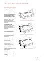
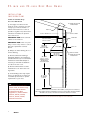
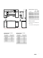
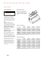
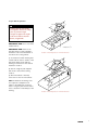
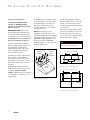
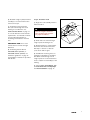
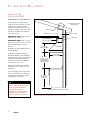
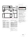
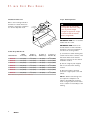
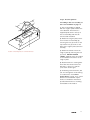
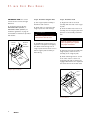
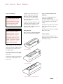
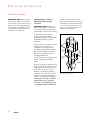
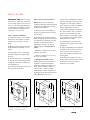
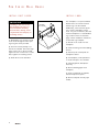
P
R O
S
E R I E S
W
A L L
H
O O D S
I
N S T A L L A T I O N
I
N S T R U C T I O N S
I
M P O R T A N T
I
N F O R M A T I O N
IMPORTANT NOTE: This
installation must be completed by a
qualified installer or service agency.
Before you begin installation, read
these instructions completely and
carefully.
• INSTALLER: please retain these
instructions for local inspector’s
reference, then leave them with the
homeowner.
• Please read the entire installation
instructions prior to installation.
• HOMEOWNER: please read and
keep these instructions for future
reference.
• Please read the entire Wolf
Pro Series Ventilation Use & Care
Information book prior to use.
As you follow these installation
instructions, take particular note of
the CAUTION and WARNING
symbols when they appear. This
information is important for the safe
and efficient installation of the Wolf
Pro Series wall hood.
CAUTION
signals a situation where minor
injury or product damage may
occur if you do not follow
instructions.
WARNING
states a hazard that may cause
serious injury or death if precautions are not followed.
In addition, the printed instructions
may signal an IMPORTANT NOTE,
which highlights information that is
especially important for a problemfree installation.
IMPORTANT NOTE: This appliance
must be installed in accordance with
National Electrical Codes, as well as
all state, municipal and local codes.
The correct voltage, frequency and
amperage must be supplied to the
appliance from a dedicated, grounded circuit which is protected by a
properly sized circuit breaker or time
delay fuse. The proper voltage,
frequency, and amperage ratings are
listed on the product rating plate.
Record the model and serial numbers
before installing the wall hood. Both
numbers are listed on the rating
plate, located on the left wall of hood
shell.
Model #
Serial #
If you have questions concerning the
installation of this product, call Wolf
Appliance Company, LLC at (800)
332-9513.
If you received a damaged wall hood
you should immediately contact your
dealer or builder.
2
P
R O
S
E R I E S
W
A L L
V
E N T I L A T I O N
H
O O D S
PRO SERIES WALL HOODS
22-inch Deep Low Profile Wall Hoods:
Available in 30", 36", 42" and 48"
widths. (R) models include mounting
holes for optional decorative rail. (I)
models include 600 cfm internal blower.
These hoods are not recommended for
use with dual fuel range, range or
rangetop with charbroiler or griddle.
12"
(305 mm)
10"
(254 mm)
48"
22"
(1219 mm)
(559 mm)
24-inch Deep Wall Hoods:
Available in 30", 36", 42", 48", 54",
60" and 66" widths. (R) models
include mounting holes for optional
decorative rail.
22-inch deep Pro Series wall hood overall dimensions
12"
(305 mm)
27-inch Deep Wall Hoods:
Available in 30", 36", 42", 48", 54",
60" and 66" widths. (R) models
include mounting holes for optional
decorative rail.
18"
(457 mm)
48"
Pro Series Wall Hood Features:
24"
(1219 mm)
(610 mm)
• Recessed controls
• Halogen lighting with night-light
24-inch deep Pro Series wall hood overall dimensions
• Hand finished with continually
welded seams
12"
• Stainless steel enclosed liner
(305 mm)
• Stainless steel baffle filters
• Transition included
• Internal or remote blower option
18"
(457 mm)
• Heat Sentry feature
• 16-gauge stainless steel shell
27"
• Top or rear discharge with certain
models
• Heat lamp (27" deep wall hoods only)
48"
(1219 mm)
(686 mm)
27-inch deep Pro Series wall hood overall dimensions
• Damper included
• Optional decorative rail assembly in
stainless, platinum, brass or copper
finish. Hood must be specifically
ordered and configured for rail
assembly.
3
22-
I N C H
A N D
24-
I N C H
D
E E P
W
A L L
H
O O D S
INSTALLATION
CONSIDERATIONS
22-inch and 24-inch Deep
Pro Series Wall Hoods
1) A straight, short duct run will
allow the hood to perform more efficiently. Try to limit the number of
elbows and transitions to as few as
possible. Long duct runs, elbows and
transitions will reduce the performance of the hood.
IMPORTANT NOTE: All hoods must
exhaust to the outdoors.
IMPORTANT NOTE: There is a possibility of noise issues, if there is a short
duct run coupled with a remote
blower.
DUCTWORK INSTALLATION
THROUGH ROOF
ROOF CAP
TRANSITION
SOFIT OR CABINET
OR DUCT COVER
10" (254 mm)
18" (457 mm)
WALL HOOD
WALL CAP
HEIGHT OF HOOD
2) Always use metal ducting. Do not
use flex ducting.
3) Wolf recommends installing a
back-draft damper in all installations
(included with hood). In cold weather
installations a back-draft damper is
necessary to minimize the backflow
of cold air into the room.
TOP DISCHARGE
8" OR 10" ROUND DUCT
REAR DISCHARGE*
22" (559 mm)
24" (610 mm)
DEPTH OF HOOD
DUCTWORK INSTALLATION
THROUGH WALL
30" TO 36"
(762 mm - 914 mm)
COOKING SURFACE
TO BOTTOM OF
VENTILATION HOOD
4) Wolf recommends the hood be
installed 30" to 36" above the cooking surface.
5) Local building codes may require
the use of make-up air. Consult your
local HVAC professional for specific
requirements in your area.
37" (940 mm)
TO COOKING
SURFACE
CAUTION
To reduce the risk of fire and
electric shock, install this range
hood only with the blowers
manufactured by Wolf
Appliance Co., Model numbers
805086, 804702, 801640,
801641, 801642, 804701,
804702 and 805347.
4
*REAR DISCHARGE IS ONLY APPLICABLE ON 22" WALL HOODS (excluding W302210I and W362210I)
AND 24" WALL HOODS USED WITH A WBLOWER-120INT (804702) OR ANY WOLF EXTERNAL BLOWER.
WBLOWER-90INT (805086) IS NOT FOR USE IN REAR DISCHARGE APPLICATIONS.
Installation dimensions for 22-inch and 24-inch deep Pro Series wall hoods.
LOCATION OF
ELECTRICAL FOR 6"
TOP DISCHARGE (152)
E
6"
(152)
5"
(127)
Shipping Weights for Blowers
E
Blower
5"
LOCATION OF
ELECTRICAL FOR
REAR DISCHARGE
(127)
10" (254)
18" (457)
HEIGHT
OF HOOD
WIDTH OF HOOD
30" TO 36"
30" TO 36"
(762 - 914)
TO COOKING
SURFACE
(762 - 914)
TO COOKING
SURFACE
22" (559)
24" (610)
DEPTH OF HOOD
COOKING SURFACE
Part Shipping
Number Weight
WBLOWER-90INT
805086
30 lbs.
WBLOWER-120INT
804702
38 lbs.
CTBLOWER-60REM
801640
35 lbs.
CTBLOWER-90REM
801641
35 lbs.
CTBLOWER-120REM
801642
39 lbs.
CTBLOWER-150REM
804701
47 lbs.
Hardware Contents:
• (10) #10 screws self tapping hex
head 2" long
• (10) 10-24 hex head flanged nuts
NOTE: Dimensions in parentheses are in millimeters.
Cabinetry and electrical placement for 22-inch and 24-inch deep Pro Series wall hoods.
Shipping Weights for 22-inch
Deep Wall Hoods
Shipping Weights for 24-inch
Deep Wall Hoods
Model Number
Shipping Weight
Model Number
Shipping Weight
W302210I
57 lbs.
W302418
67 lbs.
W362210I
63 lbs.
W362418
78 lbs.
W362210
44 lbs.
W422418
86 lbs.
W422210
50 lbs.
W482418
96 lbs.
W482210
55 lbs.
W542418
106 lbs.
W602418
116 lbs.
W662418
126 lbs.
5
22-
I N C H
A N D
24-
I N C H
D
E E P
W
A L L
H
O O D S
INSTALLATION
Step 1: Install Ductwork
WARNING
To reduce the risk of fire, use
only metal ductwork.
Installation Dimensions
Refer to the following illustration
and charts for critical dimensions
needed for the proper installation
of a 22-inch or 24-inch deep wall
hood.
B
HEIGHT OF
TRANSITION
TO CENTER
OF TRANSITION
D
CL
C
1) Decide where the ductwork will
run between the hood and the
outside of the home. Your Wolf hood
has an adjustable discharge location
which can run vertically or horizontally.
NOTE: Rear discharge is only
applicable on 22-inch wall hoods
(excluding W302210I and W362210I)
and 24-inch wall hoods used with a
WBLOWER-120INT (804702) or any
Wolf remote blower. WBLOWER90INT (805086) is not for use in rear
discharge applications.
CL
TO CENTER
OF TRANSITION
A
WIDTH
OF HOOD
22-inch Deep Wall Hoods
Model Number
Width
of Hood (A)
Height of
Transition (B)
To Center of
Transition (C)
To Center of
Transition (D)
W302210I
30" (762)
7 1/2" (191)
15" (381)
4 11/16" (119)
IMPORTANT NOTE: All hoods must
exhaust to the outdoors.
W362210I
36" (914)
7 1/2"
(191)
18" (457)
4 11/16" (119)
W362210
36" (914)
7 1/2" (191)
18" (457)
4 11/16" (119)
2) When not installing a remote
blower, always install a roof or wall
cap. Connect 8" (22-inch deep
hoods) or 10" (24-inch deep hoods)
round metal ductwork to the cap and
work back towards the hood location.
W422210
42" (1067)
7 1/2" (191)
21" (533)
4 11/16" (119)
W482210
48" (1219)
7 1/2" (191)
24" (610)
4 11/16" (119)
3) Use duct tape to seal the joints
between the ductwork sections.
4) Your Wolf wall hood comes standard with a back-draft damper
included in the transition assembly.
An additional back-draft damper is
not required.
NOTE: Dimensions in parentheses are in millimeters.
24-inch Deep Wall Hoods
Model Number
Width
of Hood (A)
Height of
Transition (B)
To Center of
Transition (C)
To Center of
Transition (D)
W302418
30" (762)
9 1/2" (241)
15" (381)
5 13/16" (148)
W362418
36" (914)
9 1/2" (241)
18" (457)
5 13/16" (148)
W422418
42" (1067)
9 1/2" (241)
21" (533)
5 13/16" (148)
W482418
48" (1219)
9 1/2"
(241)
24" (610)
5 13/16" (148)
W542418
54" (1372)
9 1/2" (241)
27" (686)
5 13/16" (148)
W602418
60" (1524)
9 1/2" (241)
30" (762)
5 13/16" (148)
W662418
66" (1676)
9 1/2" (241)
33" (838)
5 13/16" (148)
NOTE: Dimensions in parentheses are in millimeters.
6
Step 2: Wall Preparation
7 1/2"
8" ROUND
17 3/4"
WARNING
Framing must be structurally
tied together and tied to ceiling
joists to provide enough
strength to support the weight
of the hood and the internal
blower, if applicable.
CL
3 1/2"
*
5"
*
16 5/8"
*
.688"
*
5"
*
IMPORTANT NOTE: Do not use duct
smaller than 8".
IMPORTANT NOTE: Wolf recommends that the hood be installed a
minimum of 30" and a maximum of
36" above the cooking surface.
*
5"
31/4"
*
5"
* DIMENSION IS 11/2"
CL
*
Location of mounting holes for 22-inch wall hood
1) Construct wood wall framing that
is flush with the interior surface of the
wall studs. Make certain that the
framing is centered over the desired
installation location.
9 1/2"
21 1/4"
CL
10" ROUND
2"
41/2"
2) Use the rough-in plate shipped
with hood to determine framing
location.
3) After wall surface is finished,
secure the hood to the wall surface.
NOTE: If additional mounting holes
are required for adequate hood
support, drill additional mounting
holes in rough-in plate and use these
holes to attach hood assembly to wall
framing.
2"
2"
8 1/2"
41/2"
20"
2"
8"
.813"
2"
41/2"
2"
2"
41/2"
2"
CL
Location of mounting holes for 24-inch wall hood
7
22-
I N C H
A N D
24-
Step 3: Hood Preparation
If installing a WBLOWER-90INT
(805086) or WBLOWER-120INT
(804702) see Installation for Internal
Blower on page 16.
IMPORTANT NOTE: Wolf recommends installing the internal blower
to the rough-in plate assembly prior
to installing hood to the wall framing.
If installing a duct cover assembly, see
duct cover installation on page 18.
1) The hood assembly is shipped
with the rough-in plate and the transition attached. The transition is
shipped upside down in the top of
the hood assembly and must be
removed and reinstalled.
I N C H
D
E E P
W
H
O O D S
4) Determine the discharge direction
for your installation and rotate back
panel accordingly. Your wall hood
back panel has been designed to
accommodate vertical or horizontal
discharge direction.
NOTE: Rear discharge is only
applicable on 22-inch wall hoods
(excluding W302210I and W362210I)
and 24-inch wall hoods used with a
WBLOWER-120INT (804702) or any
Wolf remote blower. WBLOWER90INT (805086) is not for use in rear
discharge applications.
5) Use rough-in plate assembly to
determine stud locations. Lift roughin plate onto desired wall location
and mark pre-drilled mounting holes
on wall surface.
Horizontal discharge requires a wall
cut-out. See illustrations for 22- and
24-inch deep wall hoods. The location of the cut-out is determined by
the hood installation height.
CAUTION
If wall framing is not available,
wall anchors must be used.
ROUGH-IN
PLATE
SHIPPING
SCREWS
2) Detach the rough-in plate / transition from the hood assembly by
removing the four (4) screws on the
top and the four (4) screws on the
back of the rough-in plate / transition
assembly.
3) Detach the transition from the
rough-in plate by removing the four
(4) screws. DO NOT DISCARD
SCREWS. Shipping screws are needed
for reinstallation of transition to the
rough-in plate.
A L L
TRANSITION
AREA OF CUT-OUT ON WALL SURFACE
17"
TOP OF 22" DEEP HOOD
4 11/16"
4 1/2"
CL
4"
8"
CENTERLINE
OF 8" ROUND
TRANSITION
CENTERLINE OF HOOD
HOOD
ASSEMBLY
Wall cut-out for 22-inch deep hood
AREA OF CUT-OUT ON WALL SURFACE
21"
TOP OF 24" DEEP HOOD
5 13/16"
101/4"
CL
Rough-in plate installation
CENTERLINE
OF 10" ROUND
TRANSITION
CENTERLINE OF HOOD
Wall cut-out for 24-inch deep hood
8
6) Re-attach rough-in plate/ transition
assembly to hood shell with screws
removed in step 2.
7) If installing a remote blower,
drill 7/8" hole through the wood
framing for conduit wires. See
Connect Remote Blower on page 17
for overall dimensions and electrical
requirements. See installation instructions provided with blower for
mounting and installation information.
IMPORTANT NOTE: Do not run
remote blower connects through
ductwork.
8) If installing internal blower
WBLOWER-90INT (805086) or
WBLOWER-120INT (804702) see
installation guidelines on page 16
and installation instructions provided
with blower.
Step 4: Install the Hood
1) Align the hood assembly with the
marked location.
SOFFIT
CAUTION
Note the weight of the hood.
Three people may be required
for proper installation.
ROUGH-IN PLATE
MOUNTING HOLES
2) Install #10 x 2" screws through
rough-in plate mounting holes.
3) Attach transition to existing ductwork with sheet metal screws. Use
duct tape or silicone to make all
joints secure and air tight.
Hood installation
4) If additional mounting holes are
required for adequate hood support,
drill additional mounting holes in
rough-in plate of hood and use these
holes to attach hood assembly to wall
framing.
5) Follow Step 6: Install Wiring, Step
7: Install Hood Filters and Drip Cups
and Final Installation on page 15.
9
27-
I N C H
D
E E P
W
A L L
H
O O D S
INSTALLATION
CONSIDERATIONS
27-inch Deep Pro Series Wall Hoods
1) A straight, short duct run will
allow the hood to perform more efficiently. Try to limit the number of
elbows and transitions to as few as
possible. Long duct runs, elbows and
transitions will reduce the performance of the hood.
DUCTWORK INSTALLATION
THROUGH ROOF
ROOF CAP
TOP DISCHARGE*
10" ROUND DUCT
IMPORTANT NOTE: All hoods must
exhaust to the outdoors.
IMPORTANT NOTE: There is a possibility of noise issues, if there is a short
duct run coupled with a remote
blower.
TRANSITION
SOFIT OR CABINET
OR DUCT COVER
18" (457 mm)
HEIGHT OF HOOD
WALL HOOD
2) Always use metal ducting. Do not
use flex ducting.
3) Wolf recommends installing a
back-draft damper in all installations
(included with hood). In cold weather
installations a back-draft damper is
necessary to minimize the backflow
of cold air into the room.
27" (686 mm)
DEPTH OF HOOD
30" TO 36"
(762 mm - 914 mm)
COOKING SURFACE
TO BOTTOM OF
VENTILATION HOOD
4) Wolf recommends the hood be
installed 30" to 36" above the cooking surface.
5) Local building codes may require
the use of make-up air. Consult your
local HVAC professional for specific
requirements in your area.
37" (940 mm)
TO COOKING
SURFACE
CAUTION
To reduce the risk of fire and
electric shock, install this range
hood only with the blowers
manufactured by Wolf
Appliance Co., Model numbers
805086, 804702, 801640,
801641, 801642 and 804701.
10
*TOP DISCHARGE ONLY FOR 27" WALL HOODS.
Installation dimensions for 27-inch deep Pro Series wall hoods.
INSTALLATION
Step 1: Install Ductwork
LOCATION OF 6"
ELECTRICAL (152)
E
WARNING
5"
(127)
18" (457)
To reduce the risk of fire, use
only metal ductwork.
HEIGHT
OF HOOD
27"
WIDTH OF HOOD
(686)
DEPTH
OF HOOD
30" TO 36"
(762 - 914)
TO COOKING
SURFACE
1) Decide where the ductwork will
run between the hood and the outside of the home. Your Wolf 27-inch
deep hood does not have an
adjustable discharge and must
discharge vertically.
30" TO 36"
(762 - 914)
TO COOKING
SURFACE
COOKING SURFACE
IMPORTANT NOTE: All hoods must
exhaust to the outdoors.
2) When not installing a remote
blower, always install a roof or wall
cap. Connect 10" round metal ductwork to the cap and work back
towards the hood location.
NOTE: Dimensions in parentheses are in millimeters.
Cabinetry and electrical placement for 27-inch deep Pro Series wall hoods.
3) Use duct tape to seal the joints
between the ductwork sections
Shipping Weights for 27-inch
Deep Wall Hoods
Shipping Weights for Blowers
Blower
Part Shipping
Number Weight
Model Number
Shipping Weight
W302718
69 lbs.
WBLOWER-90INT
805086
30 lbs.
W362718
80 lbs.
WBLOWER-120INT
804702
38 lbs.
W422718
88 lbs.
CTBLOWER-60REM
801640
35 lbs.
W482718
98 lbs.
CTBLOWER-90REM
801641
35 lbs.
W542718
108 lbs.
CTBLOWER-120REM
801642
39 lbs.
W602718
118 lbs.
CTBLOWER-150REM
804701
47 lbs.
W662718
128 lbs.
4) Your Wolf wall hood comes standard with a back-draft damper
included in the transition assembly.
An additional back-draft damper is
not required.
Hardware Contents:
• (10) #10 screws self tapping hex
head 2" long
• (10) 10-24 hex head flanged nuts
11
27-
I N C H
D
E E P
W
H
A L L
O O D S
Installation Dimensions
Refer to the following illustration
and chart for critical dimensions
needed for the proper installation
of a 27-inch deep wall hood.
Step 2: Wall Preparation
B
HEIGHT OF
TRANSITION
WARNING
Framing must be structurally
tied together and tied to ceiling
joists to provide enough
strength to support the weight
of the hood and the internal
blower, if applicable.
TO CENTER
OF TRANSITION
D
CL
C
CL
TO CENTER
OF TRANSITION
A
WIDTH
OF HOOD
27-inch Deep Wall Hoods:
Model Number
Width
of Hood (A)
Height of
Transition (B)
To Center of
Transition (C)
To Center of
Transition (D)
W302718
30" (762)
9 1/2" (241)
15" (381)
5 13/16" (148)
W362718
36" (914)
9 1/2"
(241)
18" (457)
5 13/16" (148)
W422718
42" (1067)
9 1/2" (241)
21" (533)
5 13/16" (148)
W482718
48" (1219)
9 1/2" (241)
24" (610)
5 13/16" (148)
W542718
54" (1372)
9 1/2" (241)
27" (686)
5 13/16" (148)
W602718
60" (1524)
9 1/2" (241)
30" (762)
5 13/16" (148)
W662718
66" (1676)
9 1/2" (241)
33" (838)
5 13/16" (148)
NOTE: Dimensions in parentheses are in millimeters.
IMPORTANT NOTE: Do not use duct
smaller than 10" round.
IMPORTANT NOTE: Wolf recommends that the hood be installed a
minimum of 30" and a maximum of
36" above the cooking surface.
1) Construct wood wall framing that
is flush with the interior surface of the
wall studs. Make certain that the
framing is centered over the desired
installation location.
2) Use the rough-in plate shipped
with hood to determine framing
location.
3) After wall surface is finished,
secure the rough-in plate to the wall
surface.
NOTE: If additional mounting holes
are required for adequate hood
support, drill additional mounting
holes in rough-in plate and use these
holes to attach hood assembly to wall
framing.
12
Step 3: Hood Preparation
9 1/2"
21 1/4"
If installing a duct cover assembly, see
duct cover installation on page 18.
CL
10" ROUND
2"
41/2"
2"
2"
8 1/2"
41/2"
20"
2"
8"
.813"
2"
41/2"
2"
2"
41/2"
2"
CL
Location of mounting holes for 27-inch wall hood
1) The hood assembly is shipped
with the rough-in plate and the transition attached. The transition is
shipped upside down in the top of
the hood assembly and must be
removed and reinstalled.
2) Detach the rough-in plate / transition from the hood assembly by
removing the four (4) screws on the
top and the four (4) screws on the
back of the rough-in plate / transition
assembly.
3) Detach the transition from the
rough-in plate by removing the four
(4) screws. DO NOT DISCARD
SCREWS. Shipping screws are needed
for reinstallation of transition to the
rough-in plate.
4) Attach transition to existing ductwork with sheet metal screws. Use
duct tape or silicone to make all
joints secure and air tight.
5) If installing a remote blower, drill
7/8" hole through the wood framing
for conduit wires. See Connect
Remote Blower on page 17 for overall
dimensions and electrical requirements. See installation instructions
provided with blower for mounting
and installation information.
13
27-
I N C H
D
E E P
W
A L L
IMPORTANT NOTE: Do not run
remote blower connects through
ductwork.
6) If installing internal blower
WBLOWER-90INT (805086) or
WBLOWER-120INT (804702) see
installation guidelines on page 16
and installation instructions provided
with blower.
ROUGH-IN
PLATE
SHIPPING
SCREWS
TRANSITION
HOOD
ASSEMBLY
H
O O D S
Step 4: Install the Rough-In Plate
Step 5: Install the Hood
1) Use rough-in plate assembly to
determine stud locations.
1) Align both ends of the hood
assembly with the ends of the roughin plate.
2) Install #10 x 1" screws through
rough-in plate into wall framing.
CAUTION
If wall framing is not available,
wall anchors must be used.
3) If additional mounting holes are
required for adequate hood support,
drill additional mounting holes in
rough-in plate and use these holes to
attach rough-in plate assembly to
wall framing.
2) Insert the back ends of the hood
assembly into the rough-in plate and
push the hood assembly toward the
wall.
CAUTION
Note the weight of the hood.
Three people may be required
for proper installation.
3) Using the hex nuts provided with
rough-in plate, secure the hood
assembly to the rough-in plate.
4) Install remaining #10 x 2" screws
in the lower section of the hood.
Verify that wall studs or framing are
engaged. Wall anchors are required if
the screws will not hit the wall stud.
Rough-in plate installation
SOFFIT
ROUGH-IN
PLATE
MOUNTING
HOLES
Hood installation
14
P
R O
S
E R I E S
W
A L L
Step 6: Install Wiring
WARNING
This ventilation hood must be
properly grounded. This unit
should be installed by a qualified electrician in accordance
with all applicable national
and local electrical codes.
H
O O D S
Step 7: Install Hood Filters and
Drip Cups
4) Remove the junction box cover
from the rough-in plate. Connect
black wire to power supply black
wire, white wire to power supply
white wire and green wire to green
wire or bare wire.
1) Remove all packaging material
from filters and drip cups.
2) Slide drip cups along bottom edge
of hood opening so lip overhangs
slightly.
5) Place all wiring connections inside
junction box and re-install on roughin plate. Make sure that wires are
secure and that no wires are pinched
between cover and box.
3) Lift filters into place. Lines of filters
must run vertically and align with
drip cups.
WARNING
Before servicing or cleaning
unit, switch power off at service
panel and lock the service disconnecting means to prevent
power from being switched on
accidentally. When the service
disconnecting means cannot be
locked, securely fasten a prominent warning device, such as a
tag, to the service panel.
4) Adjust filters to fill space by sliding
filters left to right.
Wiring Diagram
Refer to the wiring diagram packaged
with the hood for more information.
Final Installation
If the Wolf logo nameplate is to be
applied to the hood, refer to page 18
for installation steps.
2 1/2"
2 1/2"
2"
2"
2 1/2"
1) Run 120 VAC, 15 amp (minimum)
circuit electrical power cable from the
service panel to the junction box in
the rough-in plate.
2 1/2"
22" deep wall hood
2 1/2"
2) Remove the knock-out and install
the conduit connector on the roughin plate hole.
2"
2 1/2"
2"
3) Feed the conduit through the hole
on top of the rough-in plate to the
junction box.
2 1/2"
2 1/2"
24" deep wall hood
2"
2 1/2"
2 1/2"
27" deep wall hood – electrical placement
15
V
E N T I L A T O R
I
N S T A L L A T I O N
INTERNAL BLOWER
IMPORTANT NOTE: Before turning
the power on, make sure the blower
is in the "OFF" position. Use wire connectors or wire nuts approved by UL
or C/UL. Refer to installation instructions provided with each blower to
verify wall or roof cut-outs.
WBLOWER-90INT (805086) or
WBLOWER-120INT (804702)
Installation
IMPORTANT NOTE: Wolf recommends installing the internal blower
to the rough-in plate assembly prior
to installing hood to the wall framing.
5) Once hood installation is complete, plug blower power cord(s) into
receptacle(s) located near the center
of the hood shell. Use clips on hood
interior to keep excess power cord
away from moving parts.
1) Assemble blower housing to
blower rough-in plate. Follow
installation instructions included with
the blower assembly for proper
installation.
2) Once blower is mounted to blower
rough-in plate, attach blower
assembly to hood rough-in plate
assembly by sliding blower rough-in
plate over weld studs and securing
with (8) nuts included in blower
mounting hardware kit.
3) Verify that blower discharge aligns
with hood back-plate discharge
cutout.
4) Once the blower is attached to the
hood rough-in plate, install the hood
rough-in plate to the wall. Be sure to
secure power cord(s) so as not to
damage or pinch while installing
hood shell. For all wall hoods follow
installation instructions beginning on
page 13. 27-inch Wall Hood Step 3:
Hood Preparation, Step 4: Install the
Rough-in Plate, Step 5: Install the
Hood, Step 6: Install Wiring and Step
7: Install Hood Filters and Drip Cups.
16
HOOD
ROUGH-IN
PLATE
BLOWER
ROUGH-IN
PLATE
BLOWER
HOUSING
Internal blower installation
REMOTE BLOWER
IMPORTANT NOTE: Before turning
the power on, make sure the blower
is in the "OFF" position. Use wire connectors or wire nuts approved by UL
or C/UL. Refer to installation instructions provided with each blower to
verify wall or roof cut-outs.
STEP 1: Plan the Installation
1) Locate the blower so the length of
the duct run and number of elbows
and transitions are kept to a minimum.
2) Where possible, blower should be
located between wall studs or roof
rafters.
3) Avoid pipes, wires or other ductwork that may be running through
the wall.
4) Be sure that there is enough space
for any transitions that may be needed between the blower and the connecting ductwork.
5) For best performance, locate transitions nearest the blower.
STEP 2: Connect Remote Blower
NOTE: Always refer to all blower
installation instructions provided with
the blower for additional mounting
and wiring instructions.
1) Remove cover from wiring box
inside of hood shell. Remove wiring
box knockout.
2) Feed 6 inches of inbound power
cable through the knockout opening
hole and into the wiring box. Secure
the cable to wiring box with an
appropriate connector for type of
cable being used. Connect leads as
follows:
• Black (L1) to black (loose) in the J
box from the switch.
• Neutral to neutral (loose) in the J
box from the switch.
3) Wiring Remote Blower: Follow
wiring instructions at the blower as
outlined in the particular blower
installation instructions. Black (L1) to
black, white (neutral) to white – or
white to blue, or white to brown
(depending on model) and green to
grounding screw. Run remote blower
cable (ROMEX) to the hood.
Feed 6 inches of ROMEX through the
knockout opening hole and into the
wiring box on the rough-in plate of
hood. Secure the cable to wiring box
with an appropriate connector.
Locate cord assembly provided with
the remote blower. The cord assembly has two leads, black (L1) and
white (neutral). Connect these leads
to the leads from the blower, black to
black and white to white.
Connect ALL green and bare wires
together to the ground screw in the
wiring box.
4) Plug cord assembly into receptacle
located near the center of the hood
shell. Use clips on hood interior to
keep excess power cord away from
moving parts.
5) Re-install wiring box cover and
screws. Make sure all wires are secure
and that no wires are pinched
between cover and box.
18"
20 3/4"
28 1/4"
21"
10"
10"
29 1/2"
10"
DIAMETER
15 1/2"
24 1/2"
14"
29 1/2"
10"
10"
DIAMETER
DIAMETER
14 3/4"
29 1/2"
101/8"
14 3/4"
29 1/2"
10 3/8"
4 3/4"
24 3/4"
Remote blower dimensions – 600 CFM
(801640) and 900 CFM (801641)
22"
7 1/4"
Remote blower dimensions – 1200 CFM
(801642)
25"
7 1/4"
Remote blower dimensions – 1500 CFM
(804701)
17
P
R O
S
E R I E S
W
A L L
H
O O D S
INSTALL DUCT COVER
INSTALL LOGO
CAUTION
Installing a duct cover assembly will impact all aspects of
hood installation including
hood location, ducting, electrical placement and adequacy of
mounting surfaces.
OPTIONAL
DUCT COVER
MOUNTING
SCREWS
1) Attach duct cover from the inside
of the hood through the filter opening using the screws provided.
2) Leave the screws partially loose
until all are installed. Check the alignment of the cover to the hood and
tighten the four corners first to secure
duct. Tighten all remaining screws.
3) Install the hood as described.
The nameplate is not pre-assembled
because there are various locations
that the logo can be installed.
Additionally, some customers prefer
not to have a nameplate on their
hood. For your convenience, Wolf has
created a template for a standardized
logo location. Please see the back
page of these installation instructions
for the Wolf logo template.
1) Decide on the location for the
nameplate.
2) Clean mounting area with rubbing
alcohol.
Duct cover installation
3) If desired, cut-out template for
nameplate location.
4) Fold template, locate placement
on hood and tape to hood surface.
5) Check alignment and adjust if
necessary.
6) Remove backing paper from
nameplate.
7) Position nameplate in template
cutout and press into place.
8) Remove template and any tape
residue.
18
P
R O
S
E R I E S
W
A L L
H
O O D
A
C C E S S O R I E S
BLOWERS
BACKSPLASHES
Internal Blowers
Remote Blowers
• 805347 – 600 CFM internal blower
factory installed with Models
W302210I, W362210I and L282212I.
• CTBLOWER-60REM (801640) –
600 CFM remote blower for 22"D
wall hoods (except 30" and 36" wide
with blower installed) and 24"D and
27"D (30" wide) wall hoods.
• WBLOWER-90INT (805086) –
900 CFM internal blower for 24"D
and 27"D (30", 36" and 42" wide)
wall hoods.
• WBLOWER-120INT (804702) –
1200 CFM internal blower for 24"D
and 27"D (48", 54", 60" and 66"
wide) wall hoods.
See blower and cooking product
chart for recommendations.
• CTBLOWER-90REM (801641) –
900 CFM remote blower for 22"D
wall hoods (except 30" and 36" wide
with blower installed), 24"D and
27"D (30", 36", 42", 48" and 54"
wide) wall hoods.
• CTBLOWER-120REM (801642) –
1200 CFM blower for 24"D and 27"D
wall hoods.
• CTBLOWER-150REM (804701) –
1500 CFM blower for 24"D and 27"D
wall hoods.
See blower and cooking product
chart for recommendations.
Stainless steel backsplashes are
available in the following sizes for all
Wolf wall hoods.
• 30BAK/DF – 30"W x 38"H
backsplash for 30" wall hoods.
• 36BAK/DF – 36"W x 38"H
backsplash for 36" wall hoods.
• 42BAK/DF – 42"W x 38"H
backsplash for 42" wall hoods.
• 48BAK/DF – 48"W x 38"H
backsplash for 48" wall hoods.
• 54BAK/DF – 54"W x 38"H
backsplash for 54" wall hoods.
• 60BAK/DF – 60"W x 38"H
backsplash for 60" wall hoods.
• 66BAK/DF – 66"W x 38"H
backsplash for 66" wall hoods.
19
P
R O
S
E R I E S
W
A L L
H
O O D
A
C C E S S O R I E S
WARMING SHELF
ASSEMBLIES
DUCT COVERS
Warming shelf assemblies are available for all Wolf wall hoods. Assembly
includes 13" stainless steel panel with
two fold-down shelves and 25" stainless steel wall shield.
Stainless steel duct covers are available in 6 and 12 inches for all Wolf
wall hoods.
• 30BAK-SPLH/DF – Warming shelf
assembly for 30" wall hoods.
• 36BAK-SPLH/DF – Warming shelf
assembly for 36" wall hoods.
• 42BAK-SPLH/DF – Warming shelf
assembly for 42" wall hoods.
• 48BAK-SPLH/DF – Warming shelf
assembly for 48" wall hoods.
• 54BAK-SPLH/DF – Warming shelf
assembly for 54" wall hoods.
• 60BAK-SPLH/DF – Warming shelf
assembly for 60" wall hoods.
• 66BAK-SPLH/DF – Warming shelf
assembly for 66" wall hoods.
20
6-inch Duct Covers for Wall Hoods
• DUC6COVER30W – 6" duct cover
for 30" wall hoods.
• DUC6COVER36W – 6" duct cover
for 36" wall hoods.
• DUC6COVER42W – 6" duct cover
for 42" wall hoods.
• DUC6COVER48W – 6" duct cover
for 48" wall hoods.
• DUC6COVER54W – 6" duct cover
for 54" wall hoods.
• DUC6COVER60W – 6" duct cover
for 60" wall hoods.
• DUC6COVER66W – 6" duct cover
for 66" wall hoods.
12-inch Duct Covers for Wall Hoods
• DUC12COVER30W – 12" duct cover
for 30" wall hoods.
• DUC12COVER36W – 12" duct cover
for 36" wall hoods.
• DUC12COVER42W – 12" duct cover
for 42" wall hoods.
• DUC12COVER48W – 12" duct cover
for 48" wall hoods.
• DUC12COVER54W – 12" duct cover
for 54" wall hoods.
• DUC12COVER60W – 12" duct cover
for 60" wall hoods.
• DUC12COVER66W – 12" duct cover
for 66" wall hoods.
DECORATIVE RAIL
ASSEMBLIES
Decorative rail assemblies are available for Wolf wall hoods in stainless
steel, platinum, brass and copper
finishes. Hood must be specifically
ordered and configured for rail
assembly. Assembly includes rail,
standoffs and mounting hardware.
Stainless Steel Finish:
• RAIL-30/SS – Decorative rail for
30" wall hoods.
• RAIL-36/SS – Decorative rail for
36" wall hoods.
• RAIL-42/SS – Decorative rail for
42" wall hoods.
• RAIL-48/SS – Decorative rail for
48" wall hoods.
• RAIL-54/SS – Decorative rail for
54" wall hoods.
• RAIL-60/SS – Decorative rail for
60" wall hoods.
• RAIL-66/SS – Decorative rail for
66" wall hoods.
Platinum Finish:
Copper Finish:
• RAIL-30/PLT – Decorative rail for
30" wall hoods.
• RAIL-30/COP – Decorative rail for
30" wall hoods.
• RAIL-36/PLT – Decorative rail for
36" wall hoods.
• RAIL-36/COP – Decorative rail for
36" wall hoods.
• RAIL-42/PLT – Decorative rail for
42" wall hoods.
• RAIL-42/COP – Decorative rail for
42" wall hoods.
• RAIL-48/PLT – Decorative rail for
48" wall hoods.
• RAIL-48/COP – Decorative rail for
48" wall hoods.
• RAIL-54/PLT – Decorative rail for
54" wall hoods.
• RAIL-54/COP – Decorative rail for
54" wall hoods.
• RAIL-60/PLT – Decorative rail for
60" wall hoods.
• RAIL-60/COP – Decorative rail for
60" wall hoods.
• RAIL-66/PLT – Decorative rail for
66" wall hoods.
• RAIL-66/COP – Decorative rail for
66" wall hoods.
Brass Finish:
• RAIL-30/BR – Decorative rail for
30" wall hoods.
• RAIL-36/BR – Decorative rail for
36" wall hoods.
• RAIL-42/BR – Decorative rail for
42" wall hoods.
• RAIL-48/BR – Decorative rail for
48" wall hoods.
• RAIL-54/BR – Decorative rail for
54" wall hoods.
• RAIL-60/BR – Decorative rail for
60" wall hoods.
• RAIL-66/BR – Decorative rail for
66" wall hoods.
21
I
M P O R T A N T
I
N F O R M A T I O N
SERVICE
INFORMATION
WOLF LOGO TEMPLATE
IMPORTANT NOTE: If the wall hood
does not operate properly, follow
these troubleshooting steps:
Use the full-scale template on the
following page when placing the
nameplate in the standardized Wolf
logo location.
• Verify that power is being supplied
to the wall hood.
• Check the electrical connections to
ensure that the installation has been
completed correctly.
• If the wall hood still does not work,
contact an authorized Wolf Factory
Authorized Service Center. Do not
attempt to repair the wall hood yourself. Wolf is not responsible for service
required to correct a faulty installation.
• To obtain the name and number of
a Wolf Factory Authorized Service
Center, call Wolf Customer Service at
(800) 332-9513 or check our website;
www.wolfappliance.com.
• When calling for service, you will
need the wall hood model and serial
numbers. Both numbers are listed on
the rating plate, located on the left
wall of hood shell.
The information and images are the copyright property of Wolf Appliance Company, LLC,
an affiliate of Sub-Zero Freezer Company, Inc. Neither this book nor any information or images
contained herein may be copied or used in whole or in part without the express written permission
of Wolf Appliance Company, LLC, an affiliate of Sub-Zero Freezer Company, Inc.
© Wolf Appliance Company, LLC all rights reserved.
22
LEFT OUTER EDGE OF HOOD
BOTTOM EDGE OF HOOD
CUT-OUT FOR LOGO PLACEMENT
FOLD LINE FOR LOGO PLACEMENT
W OLF A PPLIANCE C OMPANY, LLC
P. O. Box 44848 • Madison, WI 53744 • 800-332-9513
www.wolfappliance.com
805048
5/03