1
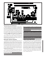
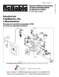
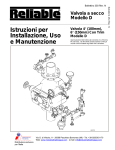
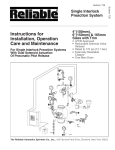
Bulletin 719 Rev. I
Instructions for
Installation, Operation,
Care and Maintenance
7 PSI (0.48 bar) Pneumatic Supervising Pressure
with Electric Actuation
Reliable Automatic Sprinkler Co., Inc., 103 Fairview Park Drive, Elmsford, New York 10523
Bulletin 719 Rev. I
Model H
Single Interlock
Preaction System
11/2” (40mm)
General Description
Reliable Single Interlock Preaction Systems are designed
for water sensitive areas which require protection from inadvertent water flow into the sprinkler system piping. Sprinkler
piping in single interlock systems can effectively be supervised by means of a Reliable Model B-SI Air Compressor
Panel, a Reliable Model C-SI Air Compressor Panel or the
Reliable Model NS-PaK. Loss of supervising pneumatic
pressure, due to a damaged sprinkler or pipe line, will not
cause water to flow through a control valve and into the system piping. A significant loss of pneumatic pressure will activate a trouble-annunciating device when system pressure
falls below the supervisory pressure switch settings (4 psi for
the B-SI and C-SI Air Compressor Panels).
When one electrical detector senses the presence of fire,
the electrical releasing control panel activates fire alarm devices and latches the solenoid releasing valve in the open
position (note that arranging detectors in a cross-zoned pattern will require operation of two detectors before the solenoid valve can open). The solenoid valve, when closed, is
preserving supply water pressure in the inlet of the Reliable
Model H Deluge Riser Assembly. Actuating the solenoid
valve releases that water pressure, allowing water flow into
the sprinkler system in readiness for the subsequent operation of a sprinkler.
To fully operate a cross-zoned single interlock system, two
electrical detectors must activate and a sprinkler must open.
During the early stages of a fire, smoke or heat activates the
first detector which causes the control panel to produce a
local alarm and an alarm at the main fire alarm panel. Electrical relays inside the releasing control panel can be used to
shut down air moving equipment or activate security doors
and other electrical devices when the panel goes into this
first alarm condition. Subsequent activation of a second,
nearby or adjacent, detector will cause the panel to energize
the solenoid valve open and release water into the sprinkler
piping. Water flowing into the sprinkler piping will simultaneously produce water pressure that causes the transfer
of contacts in the pressure switch mounted in the Riser Assembly. This switch can electrically initiate the shutdown or
startup of equipment, such as computers or other second
alarm devices. The flow of water into the sprinkler piping effectively converts the dry system into a wet pipe system. In
the event the fire subsequently produces sufficient heat to
operate a sprinkler head, water will flow from that sprinkler,
controlling or suppressing the fire.
The major benefits of a single interlock preaction system,
when compared with a wet pipe system, are as follows:
A. A fire alarm sounds prior to the operation of a
sprinkler, which may enable extinguishing the
fire by handheld means before the operation of
any sprinkler head occurs.
B. A trouble annunciator signals whenever the integrity of piping or sprinklers is accidentally or
intentionally disturbed; however, no water flow or
water damage will result at that time.
C. Speedy detection and an early fire alarm are provided by fire detectors, without the delay associated with water delivery time in the event of a fire.
Note that with a wet pipe system, the fire alarm is
delayed until after water has begun flowing from
an operated sprinkler head.
A Hydraulic Manual Emergency Releasing Station is standard equipment in the Model H Riser Assembly. It is identified by a nameplate attached above the releasing valve.
A Preaction Trim Kit is available to provide a bypass drain
line and to attach the air or nitrogen supply required to supervise the preaction system at 7 psi (0.48 bar). This kit includes a UL Listed Reliable Model G Right Check Checkä
supplied with rigid grooved pipe couplings, as illustrated in
Figure 2.
Approvals
The 1½” Reliable Single Interlock Preaction System is Underwriters Laboratories, Inc. Listed in the Special System
Water Control Valves - Deluge Type (VLFT) category. It is
also Listed by Underwriters’ Labortory of Canada. The Model G Right Check™ Valve is Listed by UL and ULC. NYC
MEA 258-93-E applies to both the Model H Assembly and
the Model G Right Checkä Valve.
Technical Data
The 1½” Reliable Single Interlock Preaction System, with
associated trim, is rated for a minimum supply pressure of
20 psi (1,4 bar) and a maximum supply pressure of 175 psi
(12 bar).
Friction loss, expressed in equivalent length of Sch. 40
pipe and based on Hazen & Williams formula with C=120,
and a flowing velocity of 15 ft/s (4.6 m/s), is 29 ft. (8.84 m)
for the Model H Riser Assembly, and 7 ft. (2.1 m) for the 2½”
(65mm) Model G Right Checkä Valve.
Shipping Weights:
Model H Riser Assembly
52 lbs. (23.6kg)
Model B-SI Compressor Panel
42 lbs (19.1kg)
Model C-SI Compressor Panel
42 lbs (19.1Kg)
NS-PaK 40 lbs (18.2Kg)
The following list of Technical Data Sheets describe the
valves and devices which are used in this system.
Deluge Riser Assembly
507
Water Flow Pressure Alarm Switch A05-0176
Pressure Maintenance Device
254
Air Compressor Panel
254
Releasing/Control Panel
Potter #5403550
Electric Emergency Station
700
Thermal Detectors700
Fire Alarm Devices
722
Automatic Nitrogen Reg. Device
253
Model G Right Check™ Valve 806
2.
System Design Considerations
Figure 1
The automatic sprinklers, air compressor, releasing devices, electric releasing control equipment, fire detection devices, manual pull stations, and signaling devices which are
utilized with the Reliable Single Interlock System must be UL
and/or ULC listed, as applicable. The Single Interlock Preaction Assembly (Figure 2) and all interconnecting piping must
be located in a readily visible and accessible location and in
an area which can be maintained at a minimum temperature
of 40°F (4°C). NOTE: HEAT TRACING IS NOT PERMITTED.
The solenoid valve is operated and supervised by the
electric releasing control panel. Details on connecting the
electrical portion of this system to a Potter PFC-4410-RC Releasing/Control Panel can by found in Reliable Bulletin 700,
“Specail Hazards & Special Systems.”
NFPA 13 is acceptable. In addition, the clapper can remain
in the closed position and the trim kit need not be isolated,
as each has been designed to withstand hydrostatic testing
as required by NFPA 13.
Hydrostatically testing the valve and trim to pressures
higher than their rating is limited to the hydrostatic test as referenced by NFPA 13. It does not address the occurrence(s)
of a “water hammer” effect, which can indeed damage the
valve. A “water hammer” in the water supply piping of the
valve can create pressures in excess of the rated pressure
and should be avoided by all necessary means. This condition may be created from improper fire pump settings,
underground construction work, or an improper venting of
trapped air in the water supply piping.
Hydrostatic Testing of Systems
System Supervising Pressure Requirements
A Reliable Model B-SI Air Compressor Panel or Model C-SI
Air Compressor Panel is used to maintain the supervising
pneumatic pressure. The Air Compressor Panel contains an
integral low air pressure warning light. The Reliable supervisory pressure sources are factory set to transfer contact
when the supervisory pressure falls below approximately 4
psi (0.48 bar). The Pressure Maintenance Device is a supervisory pneumatic supply for use where a clean, dependable
and continuous (7 days per week at 24 hours per day) plantwide compressed air or dry nitrogen gas source is available
in a 40 to 100 psi (2,8 to 6,9 bar) pressure range. Detailed
information on these supervisory pressure sources can be
found in Reliable Bulletin 254.
As required by NFPA 13, fire sprinkler systems with working pressures up to and including 150 psi are to be hydrostatically tested at a water pressure of 200 psi and maintain
that pressure without loss for two hours. Fire sprinkler systems with working pressures above 150 psi are required to
be hydrostatically tested at 50 psi above the system working pressure and maintain that pressure without loss for two
hours. In addition to the hydrostatic tests described above,
dry pipe and double interlock preaction systems require an
additional low pressure air test.
In some cases, hydrostatic testing (in accordance with the
NFPA 13 requirements noted above) will result in pressures
that exceed the working pressure of the valve and trim kit for
the two-hour test period. The valve and applicable trim kit
have been tested, approved and listed under these conditions and as such, hydrostatic testing in accordance with
3.
Figure 2 — Single Interlock Preaction Assembly
System Supervising Pressure Requirements
- Cont’d
Item
No.
In some circumstances, such as when dry sprinklers are
being used in a preaction system, it may be desirable to
supervise the preaction system at air pressures higher than
7 psi. For such cases, Reliable recommends the use of the
NS-Pak or a Model A-2 air maintenance device with either
a System Sensor EPS-10 or EPS-40 low air pressure switch.
Supervising air pressure may be between 7 psi and 20 psi,
depending on which low air pressure switch is being utilized.
1
System Electrical Requirements
All releasing, alarm and detection devices in the Single Interlock System are supervised by the Potter PFC-4410-RC
Releasing/Control Panel. Typical connection of these devices is shown in Figure 1. The power supply, standby emergency power supply, battery charger and rectifier circuitry
are all contained within the Panel. Batteries that provide
90 hours of standby power are required in FM Approved
systems. For additional information and detailed wiring diagrams, refer to Reliable Bulletin 700.
Description
6107020000 Valve, Riser Check, 2½” Model G
No.
Req’d
1
2
98050002
Reducer, 2½” Grv. x 2” NPT, 2¾” Lg.
1
3
98050003
Reducer, 2½” Grv. x 1½” NPT, 2¾” Lg.
1
4
98543234
Nipple, ¾” x 3½” Lg. (Galv.)
1
5
98543231
Nipple, ¾” x 3” Lg. (Galv.)
1
6
98543279
Nipple, ¾” x Close (Galv.)
1
7
98815202
Union, ¾” (Galv.)
1
8
98840113
Valve, Angle, ¾”
1
9
750510100 Coupling, Rigid, 2½” NPT
2
10
98048035
Bushing 1¼” x ¾”
1
11
98614403
Plug, ¼” (Galv.)
1
12
98543212
Nipple ½” x Close (Galv.)
1
13
98543220
Nipple, ¼” x 3” Lg. (Galv.)
1
14
98048000
Bushing, Reducer, ½” x ¼” (Galv.)
1
15
98761651
Tee, ½” (Galv.)
1
16
98840160
Valve, 3-Way Gauge, ¼”
1
98248000
Gauge, Air Pressure
1
17
4.
Part No.
18
6501200112 Preaction Trim Kit
19
6503003001 Model H Riser Assembly
1
Figure 3 — Single Interlock Preaction, Component Identification
System Operation
Preaction Trim Kit
To activate a Reliable Single Interlock System, two independent events must coexist before water can flow from the
system to the fire. First, an electrical detector (two detectors in a cross-zoned system) must activate to fill the system
with water, and subsequently, a sprinkler head must open
to discharge water on the fire. When a fire is detected, the
releasing control panel energizes the solenoid valve open
and water flows from the supply through the riser assembly to the system and to the alarm initiating pressure switch.
The valve maintains its open position until the solenoid is
de-energized.
Caution: The solenoid valve must be maintained open to
prevent automatic closing of the Model H Deluge Riser Assembly. The Potter PFC-4410-RC Releasing/Control Panel
has a latching feature for this purpose.
After system shutdown, the riser assembly is easily reset
without special tools. Restore detection devices by resetting
or replacing any operated device. Once detection devices
are restored, reset the releasing control panel (see Bulletin
700) and the supply pressure (see Bulletin 507).
The Preaction Trim Kit (P/N 6501200112) consists of items
1 through 17. The illustrated (Figure 2) assembly has a
convenient arrangement for draining the sprinkler system
through the Model H Riser Assembly drain line. Assemble
the Preaction Trim Kit using a suitable Teflon-based pipe
thread sealant applied to each male thread. Assemble rigid
couplings by first applying a thin coat of silicone or other
lubricant that does not contain hydrocarbons to the lips and
outside surfaces of the gasket. Position gaskets uniformly on
the valve and adjacent reducers so that all grooves are exposed. Place coupling housings over gaskets and engage
the housing keys in the grooves. Insert bolts and tighten nuts
alternately until housing halves are drawn together uniformly.
5.
Single Interlock Riser Installation
Maintenance
The recommended sequence of installation is as follows
(refer to Figures 2 and 3):
1. Install the Deluge Riser Assembly portion in accordance with Bulletin 507, “Model H Deluge Riser
Assembly.
2. Install the Model G Right Check™ Valve above the
Model H Riser Assembly using threaded/grooved
reducers and rigid grooved couplings supplied
with the Preaction Trim Kit.
3. Connect the bypass drain line between the 1 NPT
(R1) port on the Right Check™ Valve and the
Model H Riser Assembly after removing its ¾” NPT
(R¾) plug. Follow instructions provided in the Preaction Trim Kit.
4. Connect the air supply line form the Reliable Air
Maintenance Device (Model B-SI Compressor
Panel, Model C-SI Compressor Panel, NS-PaK or
Model A-2 AMD) to the ½” NPT (R 1/2) port on the
Right CheckTM Valve.
The Reliable Single Interlock System and associated
equipment shall periodically be given a thorough inspection
and test. NFPA 25, Inspection, Testing and Maintenance
of Water Based Fire Protection Systems, provides minimum maintenance requirements. A single interlock system
should be tested, operated, cleaned and inspected at least
annually, and parts replaced as required. Refer to Bulletin
507 for information regarding maintenance of the solenoid
valve and the manual emergency station valve. Bulletin 254
provide information on the Reliable Air/Nitrogen Automatic
Pressure Maintenance Devices. Bulletin 806 describes the
Model G Right Check™ Valve.
Figure 4 — Single Interlock Preaction System
6.
Resetting Single Interlock System
Testing Detection System Without
Causing Water Flow
Refer to Figure 3.
1. Close the valve controlling water supply to the riser
assembly and shut off the system air supply.
2. Open both drain valves and the manual emergency
station valve to drain the system through the riser assembly.
3. Open any low point drain valves and vents throughout the system, closing all drain valves and vents
when draining of water has stopped.
4. Inspect and replace any portion of the sprinkler system and detection system exposed to fire conditions.
Reset detectors and Potter PFC-4410-RC Releasing/
Control Panel (refer to Bulletin 700). This action will
also close (reset) the solenoid valve.
5. Reset the riser assembly in accordance with Bulletin
507, “Model H Deluge Riser Assembly Instructions
for Installation, Operation, Care and Maintenance.”
6. Restore the system supervisory by activating the
Reliable Air/Nitrogen Pressure Maintenance Device
(Refer to Bulletin 254).
7. Verify that the supervised control valve is open, and
proper monitoring has been restored. Also verify
there is no leakage from the automatic drain valve,
thereby confirming that supply water is not leaking
into the system.
Refer to Figure 3 and 4.
1. Close the isolating valve controlling water supply
to the riser assembly, and note the water pressure
gauge reading. Also, close supervisory pressure
supply line to the system.
2. Operate the detection system - operate a crosszoned releasing control panel by operating two detectors (refer to Bulletin 700, “Special Hazards &
Special Systems” for details).
3. Operation of the detection system must result in a
sudden drop of water pressure as the solenoid
valve opens. When the water pressure gauge drops
to zero; open main drain valve, bypass drain valve
and manual emergency station valve until all water
above the Isolating Valve drains away.
4. Reset detection system - reverse operations performed in Step “2” above. All detection devices must
be reset before the Potter PFC-4410-RC Releasing/Control Panel can be reset. The solenoid valve
closes when the releasing panel is reset. Close the
bypass drain valve and manual emergency station
valve.
5. Open slightly the isolating valve controlling water
supply to the riser assembly, closing the main drain
valve when water flows steadily. Open slowly but
fully the isolating valve and monitor it properly.
6. It is necessary to shut down the supervisory pressure supply (ref. Step “1”) during testing; otherwise,
low pressure annunciation can occur when the drain
valves are opened in Step “3”. Restore the supervisory pressure to 35 oz/in2 (2 psi or 0,14 bar) at this
time.
Inspection and Testing
Refer to Figures 3 and 4.
1. Water supply - be sure the valve controlling water
supply to the riser assembly is open fully and monitored properly.
2. Other trimming valves - check that all pressure gauge
valves are open. Verify that gauges are indicating
proper supervisory and water pressure readings.
3. Check that system supervisory pressure is approximately 7 psi or 0.48 bar.
4. Test water flow alarm devices by opening alarm test
valve. After closing alarm test valve, push plunger
into automatic drain valve to verify that all water is
drained from the alarm line.
5. The automatic drain valve monitors the possibility
of leakage past the solenoid valve or manual emergency station valve. Push the plunger inward, and if
no water discharges and the drip cup is dry, the riser
assembly is leak tight.
6. 6.
7. Operation test - operate by electrical actuation (refer to Bulletin 700, ”Special Hazards & Special Systems,” for details).
Note: An operational test will cause water flow throughout
the riser assembly and into the system. Where difficulty in
performance is experienced, contact Reliable Technical
Services before any field adjustment is to be made.
7.
Ordering Information
Specify (Ref. Figure 4):
Item
No.
Component Part
Mfr.
1
Deluge Riser Assembly
2
Preaction Trim
Description
Technical Bulletin
B
Model H
507
B
Refer to Parts List in this Bulletin
719
Releasing / Control Panel
Model PFC-4410-RC
12 VDC, 12 AMP Hours (90 Hours Backup) FM
Batteries
3
12 VDC, 7 AMP Hours (60 Hours Backup)
C
CA2Z (Class A Wiring Module for Initiating Circuits)
Potter 50
Reliable 700
CAM (Class A Wiring Module for Indicating Circuits)
Optional Accessories
ARM-1 / ARM-2 (Auxiliary Relay Module)
RA-4410-RC (Remote Annunciator)
Model SSM24-8 24 VDC / Polarized Bell
4
Alarm Annunciator
A
Model SSM24-10 24 VDC / Polarized Bell
Model MA24-D 24 VDC / Polarized Sounder
Reliable 700
Model MASS24LO 24 VDC / Polarized Sounder Strobe
Model SSM24-6 24 VDC / Polarized Bell
5
Trouble Annunciator
A
6
Manual Emergency Station (Elec.)
A
7
Detection
Various
Smoke, Heat Detectors, etc.
Reliable 722
8
Sprinklers
B
Closed Type
Reliable 110, 117,
131, 136, etc.
Model MA24-D 24 VDC / Polarized Sounder
Model BNG-1 (SPDT) 1 & 2 Area Detection
Model BNG-1F (DPDT) Cross Zoned Detection
Reliable 700
Reliable 700
Model B-SI Air Compressor Panel
9
Supervisory Air Pressure Supply
B
Model C-SI Air Compressor Panel
Model A-2 AMD
NS-PaK
System Equipment Manufacturers
Patents
(A)Notifier
(B) The Reliable Automatic Sprinkler Co., Inc.
(C) Potter Electric Signal Company
U.S. Patent No. 5,720,351
8.
Reliable 254
9.
Installation Dimensions in Inches
SOLENOID VALVE INSPECTIONS, TESTS AND MAINTENANCE
WARNING: THE OWNER IS RESPONSIBLE FOR MAINTAINING THE FIRE PROTECTION SYSTEM IN PROPER
OPERATING CONDITION. ANY SYSTEM MAINTENANCE OR TESTING THAT INVOLVES PLACING A CONTROL
VALVE OR DETECTION SYSTEM OUT OF SERVICE MAY ELIMINATE THE FIRE PROTECTION OF THAT SYSTEM. PRIOR TO PROCEEDING, NOTIFY ALL AUTHORITIES HAVING JURISDICTION. CONSIDERATION SHOULD
BE GIVEN TO EMPLOYMENT OF A FIRE PATROL IN THE AFFECTED AREA.
WARNING: PRIOR TO OPERATING THE SOLENOID VALVE, BE SURE TO CLOSE THE SYSTEM CONTROL
VALVE TO AVOID UNINTENTIONAL OPERATION OF THE DELUGE VALVE
1. Inspections: It is imperative that the system be inspected and tested in accordance with NFPA 25 on a regular
basis. The frequency of the inspections may vary due to contaminated water supplies, corrosive water supplies, or
corrosive atmospheres. In addition, the alarm devices, detection systems, or other connected trim may require a
more frequent schedule. Refer to the system description and applicable codes for minimum requirements.
2. The valve must be inspected at least monthly for cracks, corrosion, leakage, etc., and cleaned, repaired, or replaced, or replaced as necessary.
3. If leakage is suspected through the solenoid valve, the valve diaphragms and seats should be inspected and if
necessary, repaired or replaced.
WARNING: CLOSE SYSTEM CONTROL VALVE, TURN OFF POWER SUPPLY, AND DEPRESSURIZE VALVE
BEFORE DISASSEMBLING VALVE. IT IS NOT NECESSARY TO REMOVE THE VALVE FROM THE PIPE LINE TO
MAKE INSPECTIONS.
4. When lubricating valve components, use high grade silicone grease (Dow Corning® 111 Compound Lubricant or
equal).
5. When reassembling, tighten parts to torque values indicated in the manufacturer’s maintenance instructions
(packed with valve).
6. After maintenance is completed, operate the valve a few times to be sure of proper operation. A metallic “click”
signifies the solenoid is operating.
7. All service must be performed by qualified personnel. Upon completion of inspections or replacement of the valve,
the entire system must be checked for proper operation. See appropriate system description and testing instructions for additional information.
The equipment presented in this bulletin is to be installed in accordance with the latest published Standards of the National Fire Protection Association, Factory
Mutual Research Corporation, or other similar organizations and also with the provisions of governmental codes or ordinances whenever applicable.
Products manufactured and distributed by Reliable have been protecting life and property for over 90 years, and are installed and serviced by the most highly
qualified and reputable sprinkler contractors located throughout the United States, Canada and foreign countries.
Manufactured by
Reliable Automatic Sprinkler Co., Inc.
(800) 431-1588 Sales Offices
(800) 848-6051 Sales Fax
(914) 829-2042 Corporate Offices
www.reliablesprinkler.com Internet Address
Recycled
Paper
Revision lines indicate updated or new data.
EG. Printed in U.S.A 08/14
P/N 9999970119