1
Bulletin 749 Rev. B
Bulletin 749 Rev. B
Model DDX
Single Interlock Preaction Systems
2” (50 mm), 2½” (65 mm), 3” (80 mm),
76 mm, 4” (100 mm), 6” (150 mm),
165 mm & 8” (200mm)
Instructions for Installation,
Operation, Care, and Maintenance
Wet Pilot Line,
Dry Pilot Line, and
Electric Actuation Trims
• Electric Release Trim Available with 175 psi
•
•
•
•
(12,1 bar) or 300 psi (20,7 bar) Rated Solenoid
Valve
Electric Release Trim and Wet Pilot Trim
Utilize 7 to 10 psi (0,5 to 0,7 bar) Pneumatic
Supervising Pressure
Dry Pilot Trim Utilize 8 psi to 28 psi (0,6 to 1,9
bar) Pneumatic Supervising Pressure
Externally Resettable Clapper
One Main Drain
Reliable Automatic Sprinkler Co., Inc., 103 Fairview Park Drive, Elmsford, New York 10523
General
lot line is directly installed to the Model DDX Deluge Valve’s
pushrod chamber. Wet pilot line sprinklers are detection devices and do not provide any water to aid in the firefighting
capability of the fire sprinkler system.
To fully operate a Wet Pilot Line Single Interlock Preaction
System, the heat from a fire must fuse a wet pilot line sprinkler/detector thereby releasing the water pressure from the
Deluge Valve’s pushrod chamber. As this water pressure is
lost in this chamber, the main water supply will open the Deluge Valve’s clapper, thereby flowing water into the fire sprinkler piping. Water flowing into the system will flow through
the intermediate chamber of the deluge valve to a mechanical sprinkler alarm (optional) and/or will simultaneously produce water pressure that causes the transfer of contacts in
the (optional) alarm pressure switch mounted in the trim. If
provided, the alarm pressure switch can electrically initiate
the shut-down or start up of equipment, such as computer,
HVAC, or other secondary alarm devices (Note: the wiring
contacts for the alarm pressure switch are the “Common”
and “A” contacts). The flow of water into the sprinkler system piping converts the dry system into a wet system. In the
event that the fire subsequently produces enough heat to
operate a fire sprinkler head, water will flow from that sprinkler, controlling or suppressing the fire.
The fire sprinkler system piping may be required to be
supervised (see NFPA 13) with air pressure. Loss of this
supervisory air due to a damaged sprinkler or the sprinkler piping will not cause the Model DDX Deluge Valve to
open. The supervisory air supply for the fire sprinkler piping
may effectively be supervised by Reliable’s Model B-SI Air
Compressor Panel or Reliable’s Model C-SI Air Compressor
Panel. Other options include the use of the Reliable NS-PaK
or Nitrogen Regulator with an approved nitrogen source, the
Reliable Model A-2 Pressure Maintenance Device with a
tank-mounted air compressor, or a tank-less air compressor
controlled by a pressure switch or the Reliable Model B-1 Air
Maintenance Device. (See Reliable Bulletin 254).
In Electric Actuation Single Interlock Preaction Systems, when one electrical detector senses the presence of
fire, the electrical releasing control panel activates fire alarm
devices and operates the normally-closed solenoid valve
(175 psi (12,1 bar) or 300 psi (20,7 bar) Rated) to the open
position (Note: Arranging detectors in a cross-zoned pattern will require operation of two detectors before the solenoid valve can open). The solenoid valve, when closed, retains sufficient water pressure in the pushrod chamber of the
Model DDX Deluge Valve to maintain it closed. Energizing
the solenoid valve relieves the water pressure, thus opening
the Deluge Valve and allowing water to flow into the sprinkler
system.
To fully operate a cross-zoned single interlock system, two
electrical detectors must activate and a sprinkler head must
open. During the early stages of a fire, smoke or heat activates the first detector, which causes the control panel to
produce a local alarm and an alarm at the main fire alarm
panel. Electrical relays inside the releasing control panel
can be used to shut down air moving equipment or activate
security doors and other electrical devices when the panel
goes into the first alarm condition. Subsequent activation of
Single Interlock Preaction Systems are designed for water
sensitive areas that require protection from inadvertent water
flow into the sprinkler system piping.
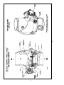
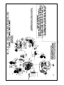
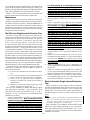
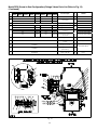
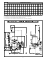
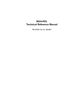
At the heart of Reliable’s Single Interlock Preaction Systems is the Model DDX Deluge Valve. This deluge valve is
a hydraulically operated, straight-through-design, differential latching clapper-type (see Fig. 1). System maintenance
is simplified since the deluge valve can be reset externally
without removing its cover plate. This feature provides a significant system-restoration time advantage. The Model DDX
Deluge Valve has an intermediate chamber and thereby
does not require an in-line air check valve. Also, for ease
of installation, the deluge valve only requires a single drain
connection.
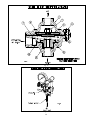
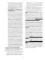
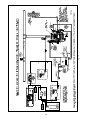
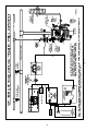
The trim sets for the single interlock preaction systems
(see Figs. 3, 4, 5, 6, 7 and 8) provide all of the necessary
equipment for connections to the Model DDX Deluge Valve’s
pushrod chamber inlet and outlet ports, a 1¼” (30 mm) main
drain on 2” (50 mm), 2½” (65 mm), 76 mm and 3” (80 mm)
valve sizes or a 2” (50 mm) main drain on 4” (100 mm), 165
mm, 6” (150 mm) and 8” (200 mm) valve sizes, alarm devices, air supply, and required pressure gauges. The trim
sets are available in individual (loose) parts, in time-saving,
segmented assembled kit forms or fully assembled to the
Model DDX Deluge Valve (with or without a control valve).
The major benefits of a single interlock preaction system,
when compared with a wet pipe or deluge system are as
follows:
• A fire alarm sounds prior to the operation of a sprinkler
head, which may enable extinguishing the fire by handheld means before the actual operation of any sprinklers
and subsequent water damage.
• A trouble annunciator signals whenever the integrity of
the piping or sprinklers is accidentally or intentionally
disturbed; however, no water flow or water damage will
occur at that time.
• Speedy detection and an early fire alarm are provided
by fire detectors, without the delay associated with water delivery time in the event of a fire. Note that with a wet
pipe system, the fire alarm is delayed until after water
has begun flowing from an operated sprinkler head.
Sprinkler piping in Wet Pilot and Electric Actuation Single
Interlock Preaction Systems can effectively be supervised
by means of a Reliable Model B-SI Air Compressor Panel or
Model C-SI Air Compressor Panel. Loss of 7 psi (0,5 bar)
supervising pneumatic pressure, due to a damaged sprinkler or sprinkler pipe will not cause water to flow through the
Model DDX Deluge Valve and into the system piping. A significant loss of pneumatic pressure will activate a troubleannunciating device when the system pressure falls below
approximately 4 psi (0,3 bar). Note: Wherever the word “air”
is used in this bulletin as a reference to the pneumatic pressure source it shall also mean “air or nitrogen.”
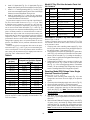
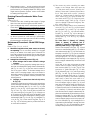
Wet Pilot Line Single Interlock Preaction Systems use
a pilot line consisting of a line of closed sprinklers or pilot
line detectors (Reliable’s Model F1-FTR), which are located
in the area to be protected. These sprinklers/detectors are
more sensitive (lower activation temperature) than the sprinkler heads installed in the fire sprinkler system. The wet pi2.
a second, nearby or adjacent, detector will cause the panel
to energize the solenoid valve open and release water into
the sprinkler system piping. Water flowing into the sprinkler
system piping will simultaneously produce water pressure
that causes the transfer of contacts in the pressure switch
mounted in the Reliable Single Interlock Preaction System’s
riser assembly. This pressure switch can electrically initiate
the shut down or startup of equipment, such as computers
or other second alarm devices. The flow of water into the
sprinkler system piping effectively converts the dry system
into a wet pipe system. In the event that the fire subsequently produces sufficient heat to operate a sprinkler head, water
will flow from that sprinkler, controlling or suppressing the
fire.
Dry Pilot Single Interlock Preaction Systems are used
in areas that may be subjected to freezing conditions. They
can also be utilized to obtain installed sprinkler heights and
pipe lengths greater than the allowed for wet pilot systems.
A dry pilot line installation consists of an air-pressurized line
of closed sprinklers or pilot line detectors (Reliable’s Model F1-FTR), which are located in the area to be protected.
NFPA 72 or the Authority Having Jurisdiction (AHJ) should
be consulted for spacing and elevation requirements for the
installation of dry pilot sprinklers/detectors.
In the system’s trim, the dry pilot line is connected to a
Model LP Dry Pilot Line Actuator. This actuator functions
very much like a miniature dry pipe valve. It requires only 8
to 28 psi (0,6 to 1,9 bar) of air pressure (depending on the
water supply pressure) to maintain the Model DDX Deluge
Valve in a closed position. In areas where moisture-laden air
could cause a freezing condition, or other problems in the
dry pilot line, the use of a dry, compressed gas such as nitrogen is suggested. Approved gas handling regulators (see
Reliable Bulletin 254) and connections are recommended.
When one of the dry pilot line sprinklers/ detectors actuates,
the air pressure in the line is reduced, thus opening the Model LP Dry Pilot Line Actuator, which in turn releases the DDX
Deluge Valve and fills the fire sprinkler piping with water.
However, water does not flow from the fire sprinkler system
until one of its sprinklers fuses from the heat of the fire.
The fire sprinkler system piping may be required to be supervised (see NFPA 13) with air pressure. Loss of this supervisory air due to a damaged sprinkler or the sprinkler piping
will not cause the Model DDX Deluge Valve to open. This is
accomplished by the ½” check valve which is located in the
valve’s trim. The check valve prevents air pressure (from the
dry pilot line) from escaping out of the Model LP Dry Pilot Line
Actuator. A low air pressure switch (System Sensor EPS40-2
or EPSA40-2) is also provided in the trim. The contacts of
this switch will close on the loss of air in the sprinkler piping,
thereby providing a low air alarm to aid in insuring the integrity of the sprinkler system piping. The pressure switch’s
low air alarm should be wired to a supervisory alarm bell or
the building’s alarm system (Note: The wiring for closing of
contacts on the loss of pressure is made on the “COM” and
“B” terminals of switch 2.)
Damage to a dry pilot line sprinkler/detector or the dry pilot line piping that causes a significant loss of pressure will
cause the Model DDX Deluge Valve to open, flowing water
into the fire sprinkler system piping. The supervisory air supply for both the dry pilot line and the fire sprinkler piping can
effectively be maintained by means of pressure-switch-operated, tank-mounted air compressor and a Reliable Model
A-2 Pressure Maintenance Device (see Reliable Bulletins
254). The compressor’s tank provides a reserve supply of
air, whereas the Model A-2 Pressure Maintenance Device
consistently regulates the air pressure of both the dry pilot
line and the fire sprinkler piping.
The dry pilot line sprinklers/detectors must be more sensitive to the heat from a fire than the sprinklers in the fire
sprinkler system. The Model F1-FTR (Fixed Temperature Release) is specifically designed for use in dry pilot line operated sprinkler systems. Dry pilot line sprinklers are detection
devices and do not provide any water to aid in the firefighting capability of the fire sprinkler system.
To fully operate a dry pilot line preaction system, the heat
from a fire must fuse a dry pilot line sprinkler/detector thereby
releasing the air pressure from the Model LP Dry Pilot Line
Actuator. The water pressure is then able to overcome the
pressure differential of the actuator, allowing water to flow
from the Model DDX Deluge Valve’s push rod chamber. As
this water pressure is lost in the push rod chamber, the supply pressure will then force the valve’s clapper open, flowing
water into the fire sprinkler system piping. Water flowing into
the system will flow through the intermediate chamber of the
deluge valve to a mechanical sprinkler alarm (optional) and/
or will simultaneously produce water pressure that causes
the transfer of contacts in the (optional) alarm pressure
switch mounted in the trim. If provided, the alarm pressure
switch can electrically initiate the shut-down or start up of
equipment, such as computer, HVAC, or other secondary
alarm devices (Note: the wiring contacts for the alarm pressure switch are the “Common” and “A” contacts). The flow
of water into the sprinkler system piping converts the dry
system into a wet system. In the event that the fire subsequently produces enough heat to operate a fire sprinkler
head, water will flow from that sprinkler, controlling or suppressing the fire.
Listings & Approvals:
(Only when used with Reliable’s Trim Sets.)
1. Reliable’s 2” (50 mm), 2½” (65 mm), 76 mm, 3” (80 mm),
4” (100 mm), 165 mm, 6” (150 mm) and 8” (200 mm) Electric Actuation Single Interlock Preaction Systems, Wet Pilot
Line Single Interlock Preaction Systems and Dry Pilot Line
Single Interlock Preaction Systems are Underwriters Laboratories, Inc. Listed and UL certified for Canada (cULus)
in the Special System Water Control Valve-Deluge Type
(VLFT) category.
2. Reliable’s 2” (50 mm), 2½” (65 mm), 76 mm, 3” (80 mm), 4”
(100 mm), 165 mm, 6” (150 mm) and 8” (200 mm) Electric
Actuation Single Interlock Preaction Systems are certified
by Factory Mutual Approvals (FM). Factory Mutual does
not approve the use of smoke detectors or cross zoned detectors in preaction systems.
3.
4.
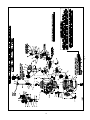
Fig. 1
System Operation
In all Reliable Single Interlock Preaction Systems, once the
clapper has opened, the lever acts as a latch, preventing the
clapper from returning to the closed position. Water from the
supply flows through the Deluge Valve into the system piping. Water also flows through the Deluge Valve alarm outlet to
the alarm devices.
After system shutdown, resetting the Model DDX Deluge
Valve is quite simple. Doing so only requires pushing in and
turning the reset knob at the rear of the valve (see Fig 1).
The external reset feature of the Model DDX Deluge Valve
provides a means for simple, economical system testing,
which is one essential facet of a good maintenance program.
The external reset feature does not, however, eliminate another important facet of good maintenance, namely, periodic
cleaning and inspection of the internal valve parts.
In the event that water builds up inside the valve due to
condensate from the air supply system or water left inside
from valve system testing, a drain is available for venting. After closing the main supply valve, a small valve over the drain
cup can be opened slightly until the water inside the valve
body and the main pipe column has drained. See the section
titled “Draining Excess/Condensate Water From System” in
this bulletin for the detailed procedure.
The Model B Manual Emergency Station (see Fig. 12) is
also included in all Reliable Single Interlock Preaction System
trim sets. It consists of an aluminum nameplate mechanically
attached to a ball valve. The valve handle in its OFF position
is guarded against accidental turning to the ON position (and
system discharge) by a nylon cable tie provided with each
trim kit. The cable tie is inserted, as shown in Fig. 12, after the
system has been restored for operation. The nylon cable tie
is designed to allow, in case of an emergency, forceful turning of the valve handle to the ON position. As an alternative to
the Model B Hydraulic Manual Emergency Station, the Model
A Hydraulic Manual Emergency Pull Box (see Reliable Bulletin 506) is also available and can be provided as an option.
Whenever ambient temperature conditions are high, the
water temperature in the Model DDX Deluge Valve’s pushrod chamber could possibly increase, thereby increasing the
pressure in the chamber to values exceeding the rated pressure of the system. In an indoor installation where standard
room temperatures are exceeded, a pressure relief kit may
be needed. Pressure relief kit, P/N 6503050001, can be installed into the pushrod chamber’s releasing line to limit the
pressure to 250 psi (17,2 bar).
Reliable Model DDX Deluge Valve with associated Single
Interlock Preaction Trims sizes 2” (50 mm), 2½” (65 mm), 76
mm, 3” (80 mm), 4” (100 mm), 165 mm, 6” (150 mm) and 8”
(200 mm) are rated for use at a minimum water supply pressure of 20 psi (1,4 bar) and a maximum water supply pressure of 250 psi (17,2 bar) for 2” (50mm), 2½” (65mm), 76mm,
3” (80mm) and 8” (200mm) valve sizes and 300 psi (20,7
bar) for 4” (100mm), 165mm and 6” (150mm) valve sizes.
Water supplied to the inlet of the valve and to the push rod
chamber must be maintained between 40˚F (4˚C) and 140˚F
(60˚C).
When set correctly for service, the Model DDX Deluge
Valve is hydraulically established to withhold the supply water from the sprinkler system piping. The Reliable Model DDX
Deluge Valve is shown in both closed and open positions in
Fig. 1. In the closed position, the supply pressure acts on the
underside of the clapper and also on the push rod through
the push rod chamber’s inlet restriction. The resultant force
due to the supply pressure acting on the push rod is multiplied by the mechanical advantage of the lever and is more
than sufficient to hold the clapper closed against normal supply pressure surges.
To fully operate (deliver water) a Wet Pilot Line Single Interlock Preaction System, two independent events must coexist
before water flow will occur. A wet pilot line sprinkler/detector
must fuse along with a fire sprinkler head. Operation of either
one of these heads will cause an alarm to annunciate, but
will not cause water discharge from the fire sprinkler system
piping.
When a fire is detected, the opened wet pilot line sprinkler/
detector vents the push rod chamber to atmosphere through
the chamber’s outlet. Since the pressure cannot be replenished through the inlet restriction as rapidly as it is vented, the
push rod chamber pressure falls instantaneously. When the
push rod chamber pressure approaches approximately onethird of the supply pressure, the upward force of the supply
pressure acting beneath the clapper overcomes the leverapplied force thereby opening the clapper.
To fully operate an Electric Actuation Single Interlock Preaction System, two independent events must coexist before
water flow will occur. One electrical detector (two detectors
in a cross-zoned system) must activate and a sprinkler head
must open. Operation of either one of these items will only
cause an alarm to annunciate, but will not cause water to
discharge from the sprinkler system piping.
When a fire is detected, the energized solenoid valve vents
the push rod chamber to atmosphere through the chamber’s
outlet. Since the pressure cannot be replenished through the
inlet restriction as rapidly as it is vented, the pushrod chamber pressure falls instantaneously. When the pushrod chamber pressure approaches approximately one-third of the supply pressure, the upward force of the supply pressure acting
beneath the clapper over comes the lever-applied force
thereby opening the clapper.
To fully operate (deliver water) a Dry Pilot Line Single Interlock Preaction System, two independent events must coexist
before water flow will occur. A dry pilot line sprinkler/detector
must fuse along with a fire sprinkler head. Operation of either
one of these heads will cause an alarm to annunciate, but
will not cause water discharge from the fire sprinkler system
piping.
When a fire is detected, the Model LP Dry Pilot Line Actuator vents the push rod chamber to atmosphere through the
chamber’s outlet. Since the pressure cannot be replenished
through the inlet restriction as rapidly as it is vented, the push
rod chamber pressure falls instantaneously.
When the push rod chamber pressure approaches approximately one-third of the supply pressure, the upward force of
the supply pressure acting beneath the clapper overcomes
the lever-applied force thereby opening the clapper.
5.
6.
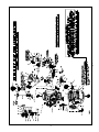
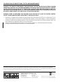
MAXIMUM PILOT LINE HEIGHT (ft)
0
10
20
30
40
50
60
70
80
90
100
110
120
0
SI
SI
I
50
20 PSI
4 0 PS
60 PS
I
80 P
100
P
100
150
200
40 PS
I
SU
PP
LY
PR
ES
SU
RE
SI
SI
125
P
150
P
SI
0P
SI
175
P
20
22
5P
SI
25
0P
SI
250
300
350
I
SI
400
80 P
450
100
P
500
SI
SI
550
125
P
Fig. 2
PIPING EQUIVALENT LENGTH (ft)
6 0 PS
600
650
700
750
800
850
22
20
175
5 P 250
0P
150
PS
PS
SI
S
PS
I
I
I
I
WET PILOT LINE HEIGHT VS LENGTH
900
7.
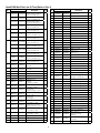
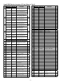
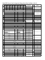
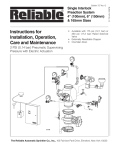
Fig. 3
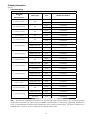
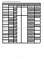
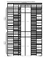
Small DDX Wet Pilot Line SI Trim (Refer to Fig. 3)
Item
No.
Part No.
Galvanized Black Pipe
Description
Item
No.
QTY.
23
95306270
95306270
Drain Hose Clip
1
24
98174404
98164402
Elbow, ¼"
1
6103022500 6103022500
Valve Assembly, 2½" (65mm)
- For 2½" Assembly Only
25
98174401
98164401
Elbow, ½"
1
26
98174402
98164400
Elbow, ¾"
1
27
98174403
98164404
Elbow, 1"
1
28
98174414
98164407
Elbow, 1¼"
1
29
96920912
96920912
Flex Line, ½"
1
30
98840172
98840172
Globe Valve, ¼"
1
31
98840171
98840171
Globe Valve, ½"
1
32
98543226
98523213
Nipple ¼" x 1½"
4
Butterfly Valve, 3"
- For 3" Assembly Only
33
98543243
98526522
Nipple ¼" x 4"
1
34
98543223
98523210
Nipple ½" x 1½"
6
Rigid Coupling, 2"
7G05080800 7G05080800
- For 2" Assembly Only
35
98543209
98523209
Nipple ½" x 2"
4
36
98543230
98523230
Nipple ½" x 3"
2
37
98543228
98523234
Nipple ½" x 4½"
1
38
98543212
98523221
Nipple ½" x Close
4
39
98543232
98523242
Nipple ¾" x 2"
1
40
98543231
98523240
Nipple ¾" x 3"
1
41
98543263
98523261
Nipple 1" x 3"
2
42
98543213
98523222
Nipple 1" x Close
1
43
98543239
98523256
Nipple 1¼" x 3"
1
44
98543250
98523264
Nipple 1¼" x 4"
1
45
98543285
98523274
Nipple 1¼" x Close
1
46
98750003
98750013
Pipe Cross, ½"
1
47
96686756
96686756
PVC Tubing, 3/8" ID x 6 ft.
1
48
98048025
98048011
Reducer Bushing, ¾" x ¼"
1
49
98048022
98048012
Reducer Bushing, ¾" x ½"
2
1
6103030000 6103030000
Valve Assembly, 76mm
- For 76mm Assembly Only
1
Valve Assembly, 3" (80mm)
- For 3" Assembly Only
Butterfly Valve, 2"
6990003549 6990003549
- For 2" Assembly Only
6215051000 6215051000
6215051200 6215051200
Butterfly Valve, 2½"
- For 2½" Assembly Only
Rigid Coupling, 2½"
7G05101000 7G05101000
- For 2½" Assembly Only
7G05121200 7G05121200
91004002
4
QTY.
Valve Assembly, 2" (50mm)
- For 2" Assembly Only
6103027600 6103027600
3
Description
6103022000 6103022000
1
2
Part No.
Galvanized Black Pipe
91004001
91004003
2
Rigid Coupling, 3"
- For 3" Assembly Only
91004002
Outlet Spool, 2"
- For 2" Assembly Only
91004001
Outlet Spool, 2½"
- For 2½" Assembly Only
91004003
1
1
Outlet Spool, 3"
- For 3" Assembly Only
5
78653000
78653000
Manual Emergency Station
Assembly
1
6
78653004
78653004
Valve Caution Station
Assembly
1
7
78653100
78653100
Ball Drip Valve, ½"
1
8
99080002
99080002
Adhesive Pad
1
9
98840101
98840101
Angle Valve, ¼"
1
50
98048015
98048015
Reducer Bushing,
2" Spigot x 1" NPTF, PVC
10
98840106
98840106
Angle Valve, 1¼"
1
51
89141112
89141112
Retaining Tie
9
98840117
Ball Valve,
¼" NPTF x ¼" NPTM
1
52
98614403
98604403
Square Head Plug, ¼"
3
53
98604406
98604402
Square Head Plug, ½"
2
98840188
Check Valve,
¼" NPTM x ¼" NPTF
1
54
98614401
98604401
Square Head Plug, ¾"
1
98840181
Check Valve,
Horizontal Swing, ½" NPT
1
55
98727607
98727607
Strainer, ¼"
1
56
98174400
98164409
Street Elbow, ½"
2
98840145
Check Valve, Horizontal
Swing, 1" NPT
1
57
98761651
98761603
Tee, ½"
1
58
98761649
98761604
Tee, ½" x ¼" x ½"
1
98840147
Check Valve,
Inline Poppet, ¼"
1
59
96606607
98761605
Tee, ½" x ½" x ¼"
2
Compression Connector,
/8" ID Tube x ¼" NPT
60
96606601
98766521
Tee, ¾"
1
1
61
96606612
98761614
Tee, ¾" x ½" x ½"
1
62
96606603
98761621
Tee, 1¼" x 1¼" x 1"
1
63
98815200
98805200
Union, ½"
2
64
98815204
98845204
Union, ½", O-ring Seal
1
65
98840160
98840160
Valve, 3-way, ¼"
2
66
98248000
98248000
Air Pressure Gauge
(0-80 psi)
1
11
12
13
14
15
16
17
18
98840117
98840188
98840181
98840145
98840147
92056702
92056703
92056810
92056702
3
92056703
Compression Connector,
Elbow 3/8" ID Tube x ¼" NPT
1
92056810
Connector,
3
/8" ID Tube x ½" NPT
1
19
92056705
92056705
3
Connector, Elbow,
/8" ID Tube x ¼" NPT
1
20
96686722
96686722
Copper Tubing, /8" OD x 2 ft.
1
21
94616917
94616917
Single Interlock Nameplate
1
67
98248001
98248001
Water Pressure Gauge
(0-300 psi)
2
22
98050004
98050004
Drain Cup, PVC
1
68
95306255
95306255
Hose Clamp
2
3
8.
9.
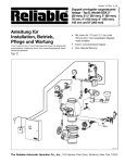
Fig. 4
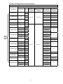
Large DDX Wet Pilot Line SI Trim (Refer to Fig. 4)
Part No.
Item
No. Galvanized Black Pipe
Description
Part No.
Item
No. Galvanized Black Pipe
QTY.
Valve Assembly, 4" (100mm)
- For 4" Assembly Only
23
98174404
98164402
Elbow, ¼"
1
24
98174402
98164400
Elbow, ¾"
2
6103040026 6103040026
Valve Assembly, 6" (150mm)
- For 6" Assembly Only
25
98174403
98164404
Elbow, 1"
1
26
98174405
98164405
Elbow, 2"
1
27
96920912
96920912
Flex Line, ½"
1
28
98840172
98840172
Globe Valve, ¼"
1
29
98840171
98840171
Globe Valve, ½"
1
30
98543226
98523213
Nipple ¼" x 1½"
1
31
98543225
98573220
Nipple ¼" x 2½"
1
32
98543220
98523219
Nipple ¼" x 3"
1
Butterfly Valve, 8"
- For 8" Assembly Only
33
98543217
98523217
Nipple ¼" x 6"
2
34
98543223
98523210
Nipple ½" x 1½"
10
Rigid Coupling, 4"
7G05161600 7G05161600
- For 4" Assembly Only
35
98543209
98523209
Nipple ½" x 2"
3
36
98543230
98523230
Nipple ½" x 3"
1
37
98543216
98523216
Nipple ½" x 3½"
1
38
98543237
98523250
Nipple ½" x 8"
1
39
98543234
98523247
Nipple ¾" x 3½"
1
40
98543279
98523241
Nipple ¾" x Close
2
41
98543222
98523224
Nipple 1" x 3½"
1
42
98543266
98523228
Nipple 1" x 6"
1
43
98543213
98523222
Nipple 1" x Close
1
44
98543262
98523262
Nipple 2" x 3½"
2
45
98543238
98523254
Nipple 2" x Close
1
46
98750003
98750013
Pipe Cross, ½"
1
47
96686756
96686756
PVC Tubing, 3/8" ID x 6 ft.
1
48
98048025
98048011
Reducer Bushing, ¾" x ¼"
1
49
98048022
98048012
Reducer Bushing, ¾" x ½"
2
1
6103060028 6103060028
6103080001 6103080001
Valve Assembly, 165mm For 165mm Assembly Only
1
Valve Assembly, 8" (200mm)
- For 8" Assembly Only
Butterfly Valve, 4"
6215051600 6215051600
- For 4" Assembly Only
6215052400 6215052400
6215053200 6215053200
3
Butterfly Valve, 6"
- For 6" Assembly Only
Rigid Coupling, 6"
7G05242400 7G05242400
- For 6" Assembly Only
7G05323200 7G05323200
91004004
4
QTY.
6103060024 6103060024
1
2
Description
91004006
91004008
2
Rigid Coupling, 8"
- For 8" Assembly Only
91004004
Outlet Spool, 4"
- For 4" Assembly Only
91004006
Outlet Spool, 6"
- For 6" Assembly Only
91004008
1
1
Outlet Spool, 8"
- For 8" Assembly Only
5
78653000
78653000
Manual Emergency Station
Assembly
1
6
78653004
78653004
Valve Caution Station
Assembly
1
7
78653100
78653100
Ball Drip Valve, ½"
1
8
99080002
99080002
Adhesive Pad
1
9
98840100
98840100
Angle Valve, 2"
1
50
98048015
98048015
Reducer Bushing,
2" Spigot x 1" NPTF, PVC
10
98840117
98840117
Ball Valve,
¼" NPTF x ¼" NPTM
1
51
89141112
89141112
Retaining Tie
9
52
98614403
98604403
Square Head Plug, ¼"
4
53
98604406
98604402
Square Head Plug, ½"
2
54
98614401
98604401
Square Head Plug, ¾"
1
55
98727607
98727607
Strainer, ¼"
1
56
98761651
98761603
Tee, ½"
1
57
98761649
98761604
Tee, ½" x ¼" x ½"
2
58
96606607
98761605
Tee, ½" x ½" x ¼"
1
59
96606601
98766521
Tee, ¾"
1
60
96606612
98761614
Tee, ¾" x ½" x ½"
1
61
96606627
98761618
Tee, 2" x 2" x 1"
1
62
98815200
98805200
Union, ½"
2
63
98815204
98845204
Union, ½", O-ring Seal
1
64
98840160
98840160
Valve, 3-way, ¼"
3
1
11
98840188
98840188
Check Valve,
¼" NPTM x ¼" NPTF
1
12
98840181
98840181
Check Valve,
Horizontal Swing, ½" NPT
1
13
98840145
98840145
Check Valve,
Horizontal Swing, 1" NPT
1
1
14
98840147
98840147
Check Valve,
Inline Poppet, ¼"
15
92056702
92056702
Compression Connector,
3
/8" ID Tube x ¼" NPT
1
16
92056703
92056703
Compression Connector,
Elbow 3/8" ID Tube x ¼" NPT
1
1
17
92056810
92056810
Connector,
3
/8" ID Tube x ½" NPT
18
92056705
92056705
Connector, Elbow,
3
/8" ID Tube x ¼" NPT
1
19
96686722
96686722
Copper Tubing, /8" OD x 2 ft.
1
20
94616917
94616917
Single Interlock Nameplate
21
98050004
98050004
22
95306270
95306270
65
98248000
98248000
Air Pressure Gauge
(0-80 psi)
1
66
98248001
98248001
Water Pressure Gauge
(0-300 psi)
2
Drain Cup, PVC
1
67
95306255
95306255
Hose Clamp
2
Drain Hose Clip
1
3
10.
11.
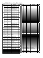
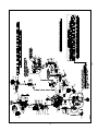
Fig. 5
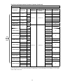
Small DDX Electric Actuation SI Trim (Refer to Fig. 5)
Part No.
Item
No. Galvanized Black Pipe
Description
6103022000 6103022000
Valve Assembly, 2" (50mm)
- For 2" Assembly Only
6103022500 6103022500
Valve Assembly, 2½" (65mm)
- For 2½" Assembly Only
1
6103027600 6103027600
6103030000 6103030000
Valve Assembly, 76mm
- For 76mm Assembly Only
Part No.
Item
No. Galvanized Black Pipe
QTY.
1
Valve Assembly, 3" (80mm)
- For 3" Assembly Only
Butterfly Valve, 2"
6990003549 6990003549
- For 2" Assembly Only
2
Butterfly Valve, 2½"
6215051000 6215051000
- For 2½" Assembly Only
6215051200 6215051200
7G05080800 7G05080800
3
91004002
4
91004001
91004003
5
Butterfly Valve, 3"
- For 3" Assembly Only
Rigid Coupling, 2"
- For 2" Assembly Only
Rigid Coupling, 2½"
7G05101000 7G05101000
- For 2½" Assembly Only
7G05121200 7G05121200
91004002
1
2
Rigid Coupling, 3"
- For 3" Assembly Only
Outlet Spool, 2"
- For 2" Assembly Only
91004001
Outlet Spool, 2½"
- For 2½" Assembly Only
91004003
Outlet Spool, 3"
- For 3" Assembly Only
6871020000 6871020000 Solenoid Valve, 175 psi Rated
6871020020 6871020020 Solenoid Valve, 300 psi Rated
1
1
Description
QTY.
23
94616917
94616917
Single Interlock Nameplate
1
24
98050004
98050004
Drain Cup, PVC
1
25
95306270
95306270
Drain Hose Clip
1
26
98174404
98164402
Elbow, ¼"
1
27
98174401
98164401
Elbow, ½"
1
28
98174402
98164400
Elbow, ¾"
1
29
98174403
98164404
Elbow, 1"
1
30
98174414
98164407
Elbow, 1¼"
1
31
96920912
96920912
Flex Line, ½"
1
32
98840172
98840172
Globe Valve, ¼"
1
33
98840171
98840171
Globe Valve, ½"
1
34
98543226
98523213
Nipple ¼" x 1½"
4
35
98543243
98526522
Nipple ¼" x 4"
1
36
98543223
98523210
Nipple ½" x 1½"
7
37
98543209
98523209
Nipple ½" x 2"
4
38
98543230
98523230
Nipple ½" x 3"
2
39
98543228
98523234
Nipple ½" x 4½"
1
40
98543212
98523221
Nipple ½" x Close
4
41
98543232
98523242
Nipple ¾" x 2"
1
42
98543231
98523240
Nipple ¾" x 3"
1
43
98543263
98523261
Nipple 1" x 3"
2
44
98543213
98523222
Nipple 1" x Close
1
45
98543239
98523256
Nipple 1¼" x 3"
1
46
98543250
98523264
Nipple 1¼" x 4"
1
47
98543285
98523274
Nipple 1¼" x Close
1
48
98750003
98761604
Pipe Cross, ½"
1
6
78653000
78653000
Manual Emergency Station
Assembly
1
96686756
96686756
PVC Tubing, 3/8" ID x 6 ft.
1
78653004
78653004
Valve Caution Station
Assembly
49
7
1
50
98048025
98048011
Reducer Bushing, ¾" x ¼"
1
8
78653100
78653100
Ball Drip Valve, ½"
1
51
98048022
98048012
Reducer Bushing, ¾" x ½"
2
1
9
99080002
99080002
Adhesive Pad
1
10
98840101
98840101
Angle Valve, ¼"
1
11
98840106
98840106
Angle Valve, 1¼"
1
12
98840117
98840117
Ball Valve,
¼" NPTF x ¼" NPTM
1
13
98840188
52
98048015
98048015
Reducer Bushing,
2" Spigot x 1" NPTF, PVC
53
89141112
89141112
Retaining Tie
9
54
98614403
98604403
Square Head Plug, ¼"
3
55
98604406
98604402
Square Head Plug, ½"
2
56
98614401
98604401
Square Head Plug, ¾"
1
57
98727607
98727607
Strainer, ¼"
1
98174400
98164409
Street Elbow, ½"
2
98840188
Check Valve,
¼" NPTM x ¼" NPTF
1
58
59
98761651
98761603
Tee, ½"
1
60
98761649
98761604
Tee, ½" x ¼" x ½"
1
61
96606607
98761605
Tee, ½" x ½" x ¼"
2
62
96606601
98766521
Tee, ¾"
1
63
96606612
98761614
Tee, ¾" x ½" x ½"
1
64
96606630
98761621
Tee, 1¼" x 1¼" x 1"
1
98815200
98805200
Union, ½"
2
1
14
98840181
98840181
Check Valve,
Horizontal Swing, ½" NPT
15
98840145
98840145
Check Valve,
Horizontal Swing, 1" NPT
1
98840147
Check Valve,
Inline Poppet, ¼"
1
92056702
Compression Connector,
3
/8" ID Tube x ¼" NPT
92056703
Compression Connector,
Elbow 3/8" ID Tube x ¼" NPT
1
65
98815204
98845204
Union, ½", O-ring Seal
1
92056810
Connector,
3
/8" ID Tube x ½" NPT
66
1
67
98840160
98840160
Valve, 3-way, ¼"
2
1
16
17
18
19
98840147
92056702
92056703
92056810
1
20
92056705
92056705
Connector, Elbow,
3
/8" ID Tube x ¼" NPT
1
21
92056704
92056704
Connector, Elbow,
3
/8" ID Tube x ½" NPT
1
22
96686722
96686722
Copper Tubing, 3/8" OD x 2 ft.
1
12.
68
98248000
98248000
Air Pressure Gauge
(0-80 psi)
69
98248001
98248001
Water Pressure Gauge
(0-300 psi)
2
70
95306255
95306255
Hose Clamp
3
13.
Fig. 6
Large DDX Electric Actuation SI Trim (Refer to Fig. 6)
Part No.
Item
No. Galvanized Black Pipe
4
5
6
98050004
98050004
Drain Cup, PVC
95306270
95306270
Drain Hose Clip
1
Valve Assembly, 6" (150mm)
6103040026 6103040026
- For 6" Assembly Only
25
98174404
98164402
Elbow, ¼"
1
26
98174402
98164400
Elbow, ¾"
2
27
98174403
98164404
Elbow, 1"
1
28
98174405
98164405
Elbow, 2"
1
29
96920912
96920912
Flex Line, ½"
1
Valve Assembly, 165mm
- For 165mm Assembly Only
1
Valve Assembly, 8" (200mm)
- For 8" Assembly Only
6215051600 6215051600
Butterfly Valve, 4"
- For 4" Assembly Only
30
98840172
98840172
Globe Valve, ¼"
1
31
98840171
98840171
Globe Valve, ½"
1
Butterfly Valve, 6"
6215052400 6215052400
- For 6" Assembly Only
32
98543226
98523213
Nipple ¼" x 1½"
1
33
98543225
98573220
Nipple ¼" x 2½"
1
34
98543220
98523219
Nipple ¼" x 3"
1
35
98543217
98523217
Nipple ¼" x 6"
2
36
98543223
98523210
Nipple ½" x 1½"
11
37
98543209
98523209
Nipple ½" x 2"
3
38
98543230
98523230
Nipple ½" x 3"
1
Rigid Coupling, 8"
7G05323200 7G05323200
- For 8" Assembly Only
39
98543216
98523216
Nipple ½" x 3½"
1
40
98543237
98523250
Nipple ½" x 8"
1
41
98543234
98523247
Nipple ¾" x 3½"
1
42
98543279
98523241
Nipple ¾" x Close
2
43
98543222
98523224
Nipple 1" x 3½"
1
44
98543266
98523228
Nipple 1" x 6"
1
45
98543213
98523222
Nipple 1" x Close
1
46
98543262
98523262
Nipple 2" x 3½"
2
47
98543238
98523254
Nipple 2" x Close
1
48
98750003
98750013
Pipe Cross, ½"
1
49
96686756
96686756
PVC Tubing, 3/8" ID x 6 ft.
1
50
98048025
98048011
Reducer Bushing, ¾" x ¼"
1
51
98048022
98048012
Reducer Bushing, ¾" x ½"
2
1
Butterfly Valve, 8"
- For 8" Assembly Only
7G05161600 7G05161600
Rigid Coupling, 4"
- For 4" Assembly Only
7G05242400 7G05242400
Rigid Coupling, 6"
- For 6" Assembly Only
91004004
91004004
Outlet Spool, 4"
- For 4" Assembly Only
91004006
91004006
Outlet Spool, 6"
- For 6" Assembly Only
91004008
91004008
Outlet Spool, 8"
- For 8" Assembly Only
6871020000 6871020000 Solenoid Valve, 175 psi Rated
6871020020 6871020020 Solenoid Valve, 300 psi Rated
78653000
1
2
1
1
78653000
Manual Emergency Station
Assembly
1
1
7
78653004
78653004
8
78653100
78653100
Ball Drip Valve, ½"
1
9
99080002
99080002
Adhesive Pad
1
10
98840100
98840100
Angle Valve, 2"
1
98840117
Ball Valve,
¼" NPTF x ¼" NPTM
98840117
52
98048015
98048015
Reducer Bushing,
2" Spigot x 1" NPTF, PVC
53
89141112
89141112
Retaining Tie
9
54
98614403
98604403
Square Head Plug, ¼"
4
55
98604406
98604402
Square Head Plug, ½"
2
1
56
98614401
98604401
Square Head Plug, ¾"
1
57
98727607
98727607
Strainer, ¼"
1
58
98761651
98761603
Tee, ½"
1
59
98761649
98761604
Tee, ½" x ¼" x ½"
2
60
96606607
98761605
Tee, ½" x ½" x ¼"
1
61
96606601
98766521
Tee, ¾"
1
62
96606612
98761614
Tee, ¾" x ½" x ½"
1
63
96606627
98761618
Tee, 2" x 2" x 1"
1
64
98815200
98805200
Union, ½"
2
65
98815204
98845204
Union, ½", O-ring Seal
1
66
98840160
98840160
Valve, 3-way, ¼"
3
67
98248000
98248000
Air Pressure Gauge
(0-80 psi)
1
68
98248001
98248001
Water Pressure Gauge
(0-300 psi)
2
69
95306255
95306255
Hose Clamp
3
1
12
98840188
98840188
Check Valve,
¼" NPTM x ¼" NPTF
13
98840181
98840181
Check Valve,
Horizontal Swing, ½" NPT
1
Check Valve,
Horizontal Swing, 1" NPT
1
98840147
Check Valve,
Inline Poppet, ¼"
1
92056702
Compression Connector,
3
/8" ID Tube x ¼" NPT
92056703
Compression Connector,
Elbow 3/8" ID Tube x ¼" NPT
1
Connector,
/8" ID Tube x ½" NPT
1
92056705
Connector, Elbow,
3
/8" ID Tube x ¼" NPT
1
1
14
15
16
17
18
19
1
6103080001 6103080001
Valve Caution Station
Assembly
11
QTY.
24
6215053200 6215053200
3
Description
23
6103060028 6103060028
2
Part No.
Item
No. Galvanized Black Pipe
QTY.
Valve Assembly, 4" (100mm)
- For 4" Assembly Only
6103060024 6103060024
1
Description
98840145
98840147
92056702
92056703
92056810
92056705
98840145
92056810
3
1
20
92056704
92056704
Connector, Elbow,
3
/8" ID Tube x ½" NPT
21
96686722
96686722
Copper Tubing, 3/8" OD x 2 ft.
1
22
94616917
94616917
Single Interlock Nameplate
1
14.
15.
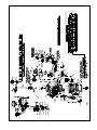
Fig. 7
Small DDX Dry Pilot Line SI (Refer to Fig. 7)
Part No.
Item
No. Galvanized Black Pipe
6103022000 6103022000
1
2
6103027600 6103027600
Valve Assembly, 76mm
- For 76mm Assembly Only
6103030000 6103030000
Valve Assembly, 3" (80mm)
- For 3" Assembly Only
6990003549 6990003549
Butterfly Valve, 2"
- For 2" Assembly Only
Butterfly Valve, 2½"
6215051000 6215051000
- For 2½" Assembly Only
7G05080800 7G05080800
4
7G05101000 7G05101000
7
8
1
Butterfly Valve, 3"
- For 3" Assembly Only
Rigid Coupling, 2"
- For 2" Assembly Only
Rigid Coupling, 2½"
- For 2½" Assembly Only
2
96686722
Copper Tubing, 3/8" OD x 2 ft.
1
94616917
94616917
Single Interlock Nameplate
1
26
98050004
98050004
Drain Cup, PVC
1
27
95306270
95306270
Drain Hose Clip
1
28
98174404
98164402
Elbow, ¼"
1
29
98174402
98164400
Elbow, ¾"
1
30
98174403
98164404
Elbow, 1"
1
31
98174414
98164407
Elbow, 1¼"
1
32
96920912
96920912
Flex Line, ½"
1
33
98840172
98840172
Globe Valve, ¼"
1
34
98840171
98840171
Globe Valve, ½"
1
35
98543226
98523213
Nipple ¼" x 1½"
4
36
98543220
98523219
Nipple ¼" x 3"
1
37
98543243
98526522
Nipple ¼" x 4"
1
38
98543223
98523210
Nipple ½" x 1½"
9
7
98523209
Nipple ½" x 2"
98543230
98523230
Nipple ½" x 3"
1
41
98543235
98523235
Nipple ½" x 8½"
1
42
98543212
98523221
Nipple ½" x Close
4
43
98543232
98523242
Nipple ¾" x 2"
1
44
98543267
98523263
Nipple ¾" x 6"
1
45
98543263
98523261
Nipple 1" x 3"
2
46
98543213
98523222
Nipple 1" x Close
1
47
98543239
98523256
Nipple 1¼" x 3"
1
48
98543250
98523264
Nipple 1¼" x 4"
1
49
98543285
98523274
Nipple 1¼" x Close
1
50
98750003
98750013
Pipe Cross, ½"
3
91004002
91004002
Outlet Spool, 2"
- For 2" Assembly Only
91004001
91004001
Outlet Spool, 2½"
- For 2½" Assembly Only
91004003
Outlet Spool, 3"
- For 3" Assembly Only
Pressure Switch (EPS40-2)
(UL/FM)
Pressure Switch (EPSA40-2)
6999992361 6999992361
(ULC)
71030010
78653000
78653004
1
71030010
Model LP Pilot Line Actuator
78653000
Manual Emergency Station
Assembly
78653004
Valve Caution Station
Assembly
1
1
51
96686756
96686756
PVC Tubing, 3/8" ID x 6 ft.
1
1
52
98048000
98048020
Reducer Bushing, ½" x ¼"
1
53
98048025
98048011
Reducer Bushing, ¾" x ¼"
1
1
54
98048022
98048012
Reducer Bushing, ¾" x ½"
2
1
78653100
78653100
Ball Drip Valve, ½"
1
99080002
99080002
Adhesive Pad
1
11
98840101
98840101
Angle Valve, ¼"
1
12
98840106
98840106
Angle Valve, 1¼"
1
98840117
Ball Valve,
¼" NPTF x ¼" NPTM
1
Check Valve,
¼" NPTM x ¼" NPTF
1
98840181
Check Valve, Horizontal
Swing, ½" NPT
2
1
15
96686722
25
98543209
9
14
24
40
10
13
QTY.
39
6999991340 6999991340
6
1
Description
Rigid Coupling, 3"
7G05121200 7G05121200
- For 3" Assembly Only
91004003
5
Part No.
Item
No. Galvanized Black Pipe
QTY.
Valve Assembly, 2" (50mm)
- For 2" Assembly Only
Valve Assembly, 2½" (65mm)
6103022500 6103022500
- For 2½" Assembly Only
6215051200 6215051200
3
Description
98840117
98840188
98840181
98840188
55
98048015
98048015
Reducer Bushing,
2" Spigot x 1" NPTF, PVC
56
98840195
98840195
Relief Valve, ½" NPT, 33 psi
1
57
89141112
89141112
Retaining Tie
9
58
98614403
98604403
Square Head Plug, ¼"
4
59
98604406
98604402
Square Head Plug, ½"
2
60
98614401
98604401
Square Head Plug, ¾"
1
61
98727607
98727607
Strainer, ¼"
1
62
98174400
98164409
Street Elbow, ½"
3
63
98761651
98761603
Tee, ½"
2
64
98761649
98761604
Tee, ½" x ¼" x ½"
2
65
96606607
98761605
Tee, ½" x ½" x ¼"
1
16
98840145
98840145
Check Valve, Horizontal
Swing, 1" NPT
17
98840147
98840147
Check Valve, Inline Poppet, ¼"
1
66
96606601
98766521
Tee, ¾"
1
18
96816904
96816904
Check Valve, Inline Poppet, ½"
1
67
96606612
98761614
Tee, ¾" x ½" x ½"
1
92056702
Compression Connector,
3
/8" ID Tube x ¼" NPT
1
68
96606603
98761621
Tee, 1¼" x 1¼" x 1"
1
69
98815200
98805200
Union, ½"
2
70
98815204
98845204
Union, ½", O-ring Seal
2
71
98840160
98840160
Valve, 3-way, ¼"
3
2
19
92056702
20
92056703
92056703
Compression Connector,
Elbow 3/8" ID Tube x ¼" NPT
1
21
92056810
92056810
Connector,
3
/8" ID Tube x ½" NPT
1
22
92056705
92056705
Connector, Elbow,
3
/8" ID Tube x ¼" NPT
1
92056704
Connector, Elbow,
3
/8" ID Tube x ½" NPT
1
23
92056704
16.
72
98248000
98248000
Air Pressure Gauge
(0-80 psi)
73
98248001
98248001
Water Pressure Gauge
(0-300 psi)
2
74
95306255
95306255
Hose Clamp
3
17.
Fig. 8
Large DDX Dry Pilot Line SI (See Fig. 8)
Part No.
Item
No. Galvanized Black Pipe
98050004
98050004
Drain Cup, PVC
95306270
95306270
Drain Hose Clip
1
Valve Assembly, 6" (150mm)
6103040026 6103040026
- For 6" Assembly Only
27
98174404
98164402
Elbow, ¼"
1
28
98174402
98164400
Elbow, ¾"
2
29
98174403
98164404
Elbow, 1"
1
30
98174405
98164405
Elbow, 2"
1
31
96920912
96920912
Flex Line, ½"
1
Valve Assembly, 165mm
- For 165mm Assembly Only
1
Valve Assembly, 8" (200mm)
- For 8" Assembly Only
6215051600 6215051600
Butterfly Valve, 4"
- For 4" Assembly Only
32
98840172
98840172
Globe Valve, ¼"
1
33
98840171
98840171
Globe Valve, ½"
1
Butterfly Valve, 6"
6215052400 6215052400
- For 6" Assembly Only
34
98543226
98523213
Nipple ¼" x 1½"
1
35
98543225
98573220
Nipple ¼" x 2½"
1
36
98543220
98523219
Nipple ¼" x 3"
2
37
98543217
98523217
Nipple ¼" x 6"
2
38
98543223
98523210
Nipple ½" x 1½"
14
39
98543209
98523209
Nipple ½" x 2"
3
40
98543230
98523230
Nipple ½" x 3"
2
41
98543216
98523216
Nipple ½" x 3½"
1
42
98543252
98523232
Nipple ½" x 10½"
1
98543234
98523247
Nipple ¾" x 3½"
(6" & 8" Versions)
1
98543282
98523253
Nipple ¾" x 4" (4" Version)
44
98543279
98523241
Nipple ¾" x Close
2
45
98543222
98523224
Nipple 1" x 3½"
1
46
98543266
98523228
Nipple 1" x 6"
1
47
98543213
98523222
Nipple 1" x Close
1
48
98543262
98523262
Nipple 2" x 3½"
2
49
98543238
98523254
Nipple 2" x Close
1
50
98750003
98750013
Pipe Cross, ½"
3
51
96686756
96686756
PVC Tubing, 3/8" ID x 6 ft.
1
52
98048000
98048020
Reducer Bushing, ½" x ¼"
1
53
98048025
98048011
Reducer Bushing, ¾" x ¼"
1
54
98048022
98048012
Reducer Bushing, ¾" x ½"
2
1
1
Butterfly Valve, 8"
- For 8" Assembly Only
7G05161600 7G05161600
Rigid Coupling, 4"
- For 4" Assembly Only
7G05242400 7G05242400
Rigid Coupling, 6"
- For 6" Assembly Only
91004004
91004004
Outlet Spool, 4"
- For 4" Assembly Only
91004006
91004006
Outlet Spool, 6"
- For 6" Assembly Only
91004008
Outlet Spool, 8"
- For 8" Assembly Only
91004008
6999991340 6999991340
5
1
6103080001 6103080001
2
Rigid Coupling, 8"
7G05323200 7G05323200
- For 8" Assembly Only
4
QTY.
26
6215053200 6215053200
3
Description
25
6103060028 6103060028
2
Part No.
Item
No. Galvanized Black Pipe
QTY.
Valve Assembly, 4" (100mm)
- For 4" Assembly Only
6103060024 6103060024
1
Description
Pressure Switch (EPS40-2)
(UL/FM)
Pressure Switch (EPSA40-2)
6999992361 6999992361
(ULC)
43
1
1
6
71030010
71030010
Model LP Pilot Line Actuator
1
7
78653000
78653000
Manual Emergency Station
Assembly
1
1
8
78653004
78653004
Valve Caution Station
Assembly
9
78653100
78653100
Ball Drip Valve, ½"
1
10
99080002
99080002
Adhesive Pad
1
55
98048015
98048015
Reducer Bushing,
2" Spigot x 1" NPTF, PVC
11
98840100
98840100
Angle Valve, 2"
1
56
98840195
98840195
Relief Valve, ½" NPT, 33 psi
1
1
57
89141112
89141112
Retaining Tie
9
58
98614403
98604403
Square Head Plug, ¼"
5
59
98604406
98604402
Square Head Plug, ½"
2
60
98614401
98604401
Square Head Plug, ¾"
1
61
98727607
98727607
Strainer, ¼"
1
62
98761651
98761603
Tee, ½"
2
63
98761649
98761604
Tee, ½" x ¼" x ½"
2
12
98840117
98840117
Ball Valve,
¼" NPTF x ¼" NPTM
13
98840188
98840188
Check Valve,
¼" NPTM x ¼" NPTF
1
14
98840181
98840181
Check Valve, Horizontal
Swing, ½" NPT
2
15
98840145
98840145
Check Valve, Horizontal
Swing, 1" NPT
1
16
98840147
98840147
Check Valve, Inline Poppet, ¼"
1
64
96606607
98761605
Tee, ½" x ½" x ¼"
1
17
96816904
96816904
Check Valve, Inline Poppet, ½"
1
65
96606601
98766521
Tee, ¾"
1
1
66
96606612
98761614
Tee, ¾" x ½" x ½"
1
67
96606627
98761618
Tee, 2" x 2" x 1"
1
68
98815200
98805200
Union, ½"
2
69
98815204
98845204
Union, ½", O-ring Seal
2
70
98840160
98840160
Valve, 3-way, ¼"
4
71
98248000
98248000
Air Pressure Gauge
(0-80 psi)
2
72
98248001
98248001
Water Pressure Gauge
(0-300 psi)
2
73
95306255
95306255
Hose Clamp
3
18
92056702
92056702
Compression Connector,
3
/8" ID Tube x ¼" NPT
19
92056703
92056703
Compression Connector,
Elbow 3/8" ID Tube x ¼" NPT
1
Connector,
/8" ID Tube x ½" NPT
1
Connector, Elbow,
/8" ID Tube x ¼" NPT
1
20
92056810
92056810
3
21
92056705
92056705
3
22
92056704
92056704
3
Connector, Elbow,
/8" ID Tube x ½" NPT
1
23
96686722
96686722
Copper Tubing, 3/8" OD x 2 ft.
1
24
94616917
94616917
Single Interlock Nameplate
1
18.
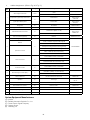
Pressurizing Line Connection
System Design Considerations
The water supply for the push-rod chamber must be provided by connection of its inlet pressurizing line to the water supply piping. Pressurizing lines for multiple Model DDX
Deluge Valve push-rod chambers must never be manifolded together, having only a single tap on the water supply
piping. Each Model DDX Deluge Valve must have its own
push-rod chamber pressurizing line connection.
This connection must be made on the supply side of the
water supply control valve (see Fig. 7 or Fig. 8). This can be
accomplished by:
• Using a tapped connection directly below or next to the
main water supply control valve using a welded outlet
or the appropriate mechanical fittings. A grooved-end
outlet coupling is one way to achieve this; or
• Using a water supply control valve that has an available
threaded (NPT) supply-side tap design to allow for a direct water supply connection to the Model DDX Deluge
Valve’s push-rod chamber.
Caution: Reliable’s DDX valve is designed with an inlet restriction built into the pushrod chamber. It is important not to
introduce additional restrictions into the direct water supply
connection or the discharge from the pushrod chamber by
installing additional valves or improperly installing the copper lines used in the trim of the valve.
The automatic sprinklers, wet pilot line sprinklers/ detectors, and signaling devices which are utilized with the Wet
Pilot Line Single Interlock Preaction System must be UL or
ULC Listed, as applicable.
The automatic sprinklers, air compressor, releasing devices, electric releasing control equipment, fire detection
devices, manual pull stations, and signaling devices which
are utilized with the Electric Actuation Single Interlock Preaction System must be UL or ULC Listed or FM Approved, as
applicable.
The automatic sprinklers, air compressor, releasing devices, electric releasing control equipment, fire detection
devices, manual pull stations, and signaling devices which
are utilized with the Dry Pilot Line Single Interlock Preaction
System must be UL or ULC Listed, as applicable.
The Deluge Valve, and all interconnecting piping must be
located in a readily visible and accessible location and in an
area that can be maintained at a minimum temperature of
40°F (4°C). Note: Heat tracing is not permitted.
Pendent sprinklers, other than dry pendents, used on preaction systems shall be installed on return bends per NFPA
13.
In Electric Actuation Single Interlock Preaction Systems,
the solenoid valve is operated and supervised by the electrical releasing/control panel.
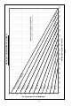
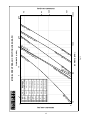
In Wet Pilot Line Single Interlock Preaction Systems, the
wet pilot line is only a detection system and does not contribute to controlling the fire. Its installation is subject to the
following restrictions:
a. It is not to be installed in an area subject to freezing.
b. It is not to be installed in an area where temperatures in excess of 150°F (65°C) are anticipated.
c. NFPA 72 or the authority having jurisdiction should
be consulted for spacing and elevation requirements.
d. Maximum wet pilot line length and height must comply with data provided in Fig. 2.
Hydrostatic Testing of DDX Valves and DDX
Systems
As required by NFPA 13, fire sprinkler systems with working pressures up to and including 150 psi are to be hydrostatically tested at a water pressure of 200 psi and maintain
that pressure without loss for two hours. Fire sprinkler systems with working pressures above 150 psi are required to
be hydrostatically tested at 50 psi above the system working pressure and maintain that pressure without loss for two
hours. In addition to the hydrostatic tests described above,
dry pipe and double interlock preaction systems require an
additional low pressure air test.
In some cases, hydrostatic testing (in accordance with the
NFPA 13 requirements noted above) will result in pressures
that exceed the working pressure of the valve and trim kit for
the two-hour test period. The valve and applicable trim kit
have been tested, approved and listed under these conditions and as such, hydrostatic testing in accordance
with NFPA 13 is acceptable. In addition, the clapper can
remain in the closed position and the trim kit need not
be isolated, as each has been designed to withstand hydrostatic testing as required by NFPA 13.
Hydrostatically testing the valve and trim to pressures
higher than their rating is limited to the hydrostatic
test as referenced by NFPA 13. It does not address the
occurrence(s) of a “water hammer” effect, which can indeed damage the valve. A “water hammer” in the water
supply piping of the valve can create pressures in excess of the rated pressure and should be avoided by all
necessary means. This condition may be created from
improper fire pump settings, underground construction
work, or an improper venting of trapped air in the water
supply piping.
19.
System Air Pressure Requirements
For Wet Pilot Single Interlock Preaction Systems and
Electric Actuation Single Interlock Preaction Systems, a
Reliable Model B-SI Air Compressor Panel or Reliable Model C-SI Air Compressor Panel can be used to maintain the
system air pressure at approximately 7 psi (0,5 bar). The
air compressor panels contain an integral low air pressure
warning light.
In some circumstances, such as when dry sprinklers are
being used in a preaction system, it may be desirable to supervise the preaction system at air pressures higher than 7
psi (0,5 bar). For such cases, Reliable recommends the use
of a tank-mounted compressor and the Reliable Model A-2
Pressure Maintenance Device. Supervising pressure may
be between 7 psi and 20 psi (0,5 and 1,4 bar).
For Dry Pilot Line Single Interlock Preaction Systems,
a Reliable Model A-2 Pressure Maintenance Device can be
used to maintain the pneumatic pressure of both the Dry
Pilot Line of detectors and the fire sprinklers to the values
shown in Table A. The values listed in the table represent the
necessary ranges of pneumatic pressure required to keep
the Model LP Dry Pilot Line Actuator in the closed position
for a given water supply pressure.
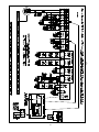
battery charger, and the rectifier circuitry are all contained
within the Potter PFC-4410-RC Releasing Control Panel. The
solenoid valve is operated and supervised by the Potter
PFC-4410-RC Releasing Control Panel. Potter PFC-4410RC Releasing Control Panel requires 120 VAC. Batteries that
provide ninety hours of standby power are required for Factory Mutual Approved systems.
Note:
Table A
Skinner Model 73212BN4TNLVN0C322C2
Rated working pressure: 300 psi (20,7 bar)
Voltage: 24 VDC
Power: 22 Watts
Current: 0.83 Amps Holding
Enclosure Coil: NEMA 4X
Pipe Size: ½” NPT Female
Cv Factor: 2.8
Water Pressure
psi (bar)
Maximum
20 (1.4)
30 (2.1)
50 (3.4)
75 (5.2)
100 (6.9)
125 (8.6)
150 (10.3)
175 (12.1)
200 (13.8)
225 (15.5)
250 (17.2)
275 (19.0)
300 (20.7)
In order for the solenoid valve to maintain Reliable’s warranty it must remain sealed as it came from the factory. If
there are concerns about the valve’s internal components,
immediate replacement is recommended.
Standard Solenoid Valve Specifications:
Skinner Model 73218BN4UNLVN0C111C2
Rated working pressure: 175 psi (12,1 bar)
Voltage: 24 VDC
Power: 10 Watts
Current: 0.41 Amps Holding
Enclosure Coil: NEMA 4X
Pipe Size: ½” NPT Female
Cv Factor: 4.0
Alternate Solenoid Valve Specifications:
Pneumatic Pressure to be
Pumped into Sprinkler System
psi (bar)
Not Less Than Not More Than
8 (0.6)
10 (0.7)
12 (0.8)
13 (0.9)
15 (1.0)
16 (1.1)
17 (1.2)
18 (1.2)
19 (1.3)
21 (1.4)
22 (1.5)
23 (1.6)
24 (1.7)
10 (.7)
14 (1.0)
16 (1.1)
17 (1.2)
19 (1.3)
20 (1.4)
21 (1.4)
22 (1.5)
23 (1.6)
25 (1.7)
26 (1.8)
27 (1.9)
28 (1.9)
Single Interlock Preaction Systems Engineering
Specification
2” (50 mm), 2½” (65 mm), 76 mm, 3” (80 mm), 4” (100 mm),
165 mm, 6” (150 mm) and 8” (200 mm)
Model DDX Deluge Valve
Preaction System shall be a Single Interlock Preaction
System utilizing a [2” (50 mm)][2½” (65 mm)][76 mm] [3”
(80 mm)][4” (100 mm)][165 mm][6” (150 mm][8” (200 mm)]
[cULus Listed] [Factory Mutual Approved] hydraulically operated, differential latching clapper type valve. Deluge valve
construction shall be of lightweight, ductile iron construction
with either a “screw in” stainless steel seat and clapper assembly or drop in bronze seat and clapper assembly. Stainless steel or Bronze seat shall have O-ring seals to resist
leakage and corrosion. Clapper facing shall be pressure
actuated, providing a limited compression seat for the sealing force between the clapper rubber facing and the valve
seat. Deluge valve shall have an external reset knob for
resetting the clapper without requiring the removal of the
valve face plate. Push-rod chamber design shall consist of
a stainless steel piston/ push-rod and spring assembly with
diaphragm seal secured to the casting through a push-rod
guide constructed of a synthetic engineering plastic to resist
corrosion. Casting shall have a bleeder hole located on the
pushrod chamber for air/water leakage indication. Trip ratio
shall be approximately a 3:1 force differential. Deluge valve
shall be of the straight through design to minimize friction
Note: During system set-up, a higher pneumatic pressure may be required in order to properly set the Model
LP Dry Pilot Line Actuator.
Whenever multiple systems area supplied by a common
air or nitrogen source, each system must have its own pressure maintenance device for individual maintenance of
pressure (NFPA 13, 7.2.6.5).
System Electrical Requirements
When Using the Electric Actuation Single Interlock Preaction System, all releasing, alarm and detection devices in
the Single Interlock Preaction System are supervised by
the Potter PFC-4410-RC Releasing Control Panel. Connect
these devices as shown in Fig. 9. The Releasing/ Control
Panel should be set to use Program #6 (See Potter Instruction Manual #5403550).
The power supply, the standby emergency power supply,
20.
21.
Fig. 9
Pneumatic Supervisory Pressure Supply Options
loss. Inlet restriction orifice shall be factory installed into the
inlet port of the deluge valve push-rod cover plate and not
be a separate part of the deluge valve trim. End connection
style to be [2” (50 mm)][2½” (65 mm)][76 mm] [3” (80 mm)]
[4” (100 mm)][165 mm][6” (150 mm][8” (200mm] grooved,
per ANSI/AWWA C606 or flanged per ASME B16.5 or ISO
7005. Deluge valve shall have a rated working pressure of
250 psi (17,2 bar) for 2” (50mm), 2½” (65mm), 76mm, 3”
(80mm) and 8” (200mm) valve sizes and 300 psi (20,7 bar)
for 4” (100mm), 165mm and 6” (150mm) valve sizes and
shall be factory hydrostatic tested at 500 psi (34,5 bar) for
2” (50mm), 2½” (65mm), 76mm, 3” (80mm) and 8” (200mm)
valve sizes and 600 psi (41,4 bar) for 4” (100mm), 165mm
and 6” (150mm) valve sizes.
Deluge valve to be [2” (50 mm)][2½” (65 mm)][76 mm] [3”
(80 mm)][4” (100 mm)][165 mm][6” (150 mm][8” (200 mm)]
Reliable Model DDX Deluge Valve (Bulletin 519).
Interlock Preaction Trims shall consist of either black pipe
or galvanized pipe and brass components specifically listed/approved with the deluge valve.
In addition, the Electric Actuation Single Interlock Preaction Trim shall include a Deluge valve releasing device to
be an electrical two-way, normally closed, pilot operated solenoid valve [cULus Listed] [FMApproved] for its intended
use. The solenoid valve shall be constructed of a brass body
with stainless steel sleeve tube, springs, stop and plunger,
and with ½” female NPT end connections. Solenoid valve
shall have a maximum working pressure of [175 psi (12,1
bar)] [300 psi (20,7 bar)] and maximum ambient temperature rating of 150°F (66°C). Power consumption of integrated
coil shall be limited to [10 watts (175 psi (12,1 bar)) Rated]
[22 watts (300 psi (20,7 bar)) Rated] and require 24 VDC
from a releasing/control panel listed for such service. Solenoid valve shall be a Skinner ½” normally-closed solenoid
valve, [Model 73218BN4UNLVNOC111C2 (175 psi (12,1
bar)) Rated]. [Model 73212BN4TNLVNOC322C2 (300 PSI
(20,7 bar)) Rated].
Dry Pilot Line Single Interlock Preaction Trim shall include
a low pressure pneumatic actuator which is constructed of
cast iron utilizing a diaphragm and compression spring design to separate the pushrod chamber water pressure from
the system piping’s pneumatic supervisory air pressure.
The low-pressure actuator shall only require between 8 and
28 psi (0,6 and 1,9 bar) supervisory air pressure for proper
setting in accordance with the manufacturers instructions.
The Low-pressure actuator shall be Reliable Model LP Dry
Pilot Line Actuator. The Dry Pilot Line Single Interlock Trim
shall also include a low air pressure switch to indicate loss
of air pressure in the system piping. The switch shall be
[UL Listed/ FM Approved][cULus Listed] and of the bellowsactivated type enclosed in a weatherproof NEMA 4X/ NEMA
4 rated enclosure incorporating tamper resistant screws.
There shall be two sets of SPDT (form C) contacts rated 10.0
A @ 125/250 VAC and 2.5 A @ 6/12/24 VDC. The pressure
switch shall have a maximum service pressure rating of 250
psi (17,2bar). Switch shall be provided with a ½” NPT male
pressure connection. Low air supervisory switch shall be
System Sensor EPS40-2.
Owner’s Air supply
Supervisory air supply shall be provided by an owner supplied air system in conjunction with a [cULus Listed] automatic pressure maintenance device, capable of maintaining
a constant system pressure regardless of pressure fluctuations in the compressed air source. The pressure maintenance device shall consist of galvanized trim and brass
parts, including a strainer and a field adjustable air pressure regulator, and have a working pressure rating of 175 psi
(12,1 bar). The pressure regulator shall have an adjustable
outlet pressure range of 5 to 100 psi (0,34 to 6,8 bar). Pressure maintenance device shall be Reliable Model A-2 (see
NFPA13).
Low Pressure Air Compressor Panel
Wet Pilot Line Single Interlock Preaction and Electric Actuation Single Interlock Preaction system supervisory air supply shall be a [cULus Listed] [FM Approved] self-contained,
low pressure air compressor panel containing a 1/16 hp air
compressor, DPDT relay for remote supervisory annunciation, low pressure warning light, pressure gauge, and low
pressure alarm switch. Pressure switch shall control the
compressor, providing a maximum operating supervisory
pressure of approximately 7 psi (0,5 bar), and a low-pressure
supervisory alarm at approximately 4 psi (0,3 bar). Power requirements shall be 120 VAC/60 Hz or 220/230 VAC/50 HZ.
Low Pressure Air Compressor Panel shall be Reliable Model
B-SI or C-SI.
Compressed Air Supply
Supervisory air supply shall be provided by an automatic
air compressor sized for the capacity (volume) of the single
interlock preaction system piping, and be capable of restoring normal air pressure in the system within the time limits
specified in NFPA 13.
Dry Pilot Line Single Interlock Preaction systems desiring a higher supervisory air pressure, shall only require
between 8 and 28 psi (0,6 to 1,9 bar) supervisory pressure
for proper setting of the low pressure pneumatic actuator in
accordance with the manufacturer’s instructions. Air supply
shall be equipped with an automatic pressure maintenance
device capable of maintaining a constant system pressure
regardless of pressure fluctuations in the compressed air
(or nitrogen) source, or system piping. The pressure maintenance device shall consist of galvanized trim and brass
parts, including a strainer and a field adjustable air pressure
regulator, or pressure switch, and have a working pressure
rating of 175 psi (12,1 bar). The pressure regulator shall have
an adjustable outlet pressure range of 5 to 100 psi (0,34 to
6,8 bar). Pressure maintenance device shall be Reliable
Model A-2 or Reliable Model B-1. (Note: For small systems
with air compressors having a capacity less than 5.5 cfm @
10 psi, a pressure maintenance device is not required per
NFPA 13. Consideration should be given, however, to the
impact of a direct air supply on the overall performance of
the system.)
22.
Nitrogen
Nitrogen cylinders provided by an approved source shall
provide the nitrogen supply. Dry Pilot Line Single Interlock
Preaction System and Wet Pilot Ling Single Interlock or Electric Actuation Single Interlock Preaction systems desiring a
higher supervisory air pressure, shall only require between
8 and 28 psi (0,6 to 1,9 bar) supervisory pressure for proper
setting of the low pressure pneumatic actuator in accordance with the manufacturer’s instructions. The nitrogen cylinder pressure shall be regulated and supervised through
the use of nitrogen regulating device and low-pressure trim
kit. This device shall consist of a brass, single stage pressure regulator, equipped with high pressure inlet and low
pressure outlet gauges, and ¼” copper connection tubing
with galvanized ¾” x ¼” reducer bushing. Optional: Lowpressure trim kit shall be included to monitor the regulated
nitrogen supply pressure to provide a low-pressure supervisory alarm. This kit shall include a low-pressure switch with
associated galvanized connection trim. Assembly shall be
a Reliable Nitrogen Regulating Device. This device is to be
used in conjunction with the Reliable Model A-2 Pressure
Maintenance Device.
shall be capable of providing any of the following desired
modes of operation: single hazard, two zone; single hazard,
cross-zoned; dual hazard, combined release; and dual hazard, split release (two area). Releasing/control panel shall be
equipped with a local tone alarm to annunciate loss of AC
power, system trouble, circuit trouble, and low auxiliary DC
power supply. Panel shall be [cULus Listed] [FM Approved]
and be capable of providing power for compatible detectors
and auxiliary devices used. Audible alarms shall be able to
be silenced at releasing panel. Auxiliary DC power supply
shall consist of (2) 12-volt lead acid batteries of the same
ampere-hour rating, providing [60 hours – cULus Listed]
[90 hours – FM Approved]. Dry contacts shall be provided
for remote annunciation of alarm, trouble, and supervisory
panel signals. Main power supply to be a dedicated a 120
VAC / 60 Hz circuit.
Technical Data
Reliable Single Interlock Preaction Systems, with associated trim, size 2” (50 mm), 2½” (65 mm), 76 mm, 3” (80 mm),
4” (100 mm), 165 mm, 6” (150 mm) & 8” (200 mm) are rated
for use at minimum water supply pressure of 20 psi (1,4 bar)
and maximum supply pressure of 250 psi (17,2 bar) for 2”
(50mm), 2½” (65mm), 76mm, 3” (80mm) and 8” (200mm)
valve sizes and 300 psi (20,7 bar) for 4” (100mm), 165mm
and 6” (150mm) valve sizes. Water supplied to the inlet of
the valve and to the pushrod chamber must be maintained
between 40°F (4°C) and 140°F (60°C).
The following list of technical bulletins pertains to valves
and devices that may be used in this preaction system:
Optional System Accessories
System Control Valve
Preaction system control valve shall be a slow close, [cULus Listed] indicating butterfly type valve with a pre-wired
supervisory tamper switch assembly. The valve shall be
rated for a working pressure of [300 psi (20,7 bar)]. System
control valve shall be for a [2” (50 mm)] Gruvlock AN77223A Butterfly Valve or [2½” (65 mm)][3” (80 mm)][4” (100
mm)][6” (150 mm][8” (200 mm] - Nibco GD-4765-8N Butterfly Valve.
Deluge Valve
Hydraulic Emergency Station (Model A)
Solenoid Valve
Mechanical Sprinkler Alarm
Pressure Maintenance Device
Nitrogen Regulating Device
Air Compressor Panel
(Models B-SI & C-SI)
Releasing/Control Panel
Pilot Line Detector
Waterflow Alarm Pressure Switch
Alarm pressure switch shall be provided to indicate water
flow and provide a water flow alarm. Pressure switch shall be
[cULus Listed] and of the bellows activated type enclosed
in a weatherproof, 4x, NEMA 4-rated enclosure incorporating tamper-resistant screws. There shall be two sets of SPDT
(Form C) contacts rated at 10.0 A @ 125/250 VAC and 2.5 A
@ 6/12/24 VDC. The pressure switch shall have a maximum
service pressure rating of 250 psi (17,2 bar) and shall be
factory adjusted to operate at a pressure of 4 to 8 psi (0,27
to 0,55 bar) with adjustment up to 20 psi (1,3 bar). Switch
shall be provided with a 1/2” NPT male pressure connection. Waterflow alarm pressure switch shall be System Sensor EPS10-2.
Waterflow Pressure Alarm Switch
Reliable 518/519
Reliable 506
Reliable 718
Reliable 612/613
Reliable 254
Reliable 254
Reliable 254
Potter #5403550
Reliable 180
System Sensor
WFDS51701
Model DDX Deluge Valve Description
1. Rated working pressure:
Valve & System - 250 psi (17.2 bar) for 2” (50mm),
21/2” (65mm), 76mm, 3” (80mm) and 8” (200mm)
valve sizes and 300 psi (20,7 bar) for 4” (100mm),
165mm and 6” (150mm) valve sizes.
2. Factory tested to a hydrostatic pressure of 500 psi
(34,5 bar) for 2” (50mm), 2½” (65mm), 76mm, 3” (80mm)
and 8” (200mm) valve sizes and 300 psi (20,7 bar) for 4”
(100mm), 165mm and 6” (150mm) valve sizes. (Valve only)
Detection System
To operate the solenoid valve on the electric actuation
preaction system, a supplemental electric detection system
shall be provided [Insert applicable product specification].
Releasing/Control Panel
A releasing/control panel shall be used to operate the
preaction system. The releasing/control panel shall be a
conventional, microprocessor-controlled panel containing
two initiating device circuits, and waterflow and supervisory
inputs. Output circuits shall include alarm, waterflow, supervisory, and releasing circuits. The releasing/control panel
23.
3. End and trim connections:
•
6. Valve Shipping Weight:
ANSI/AWWA C606 grooved inlet and outlet
Nominal
Pipe Size
Outlet
Diameter
Groove
Diameter
Groove
Width
Outlet
Face to
Groove
2” (50 mm)
2.375”
(60mm)
2.250”
(57mm)
11/32”
(9.0mm)
5/8”
(16mm)
2½” (65 mm)
2.875”
(73mm)
2.720”
(69mm)
11/32”
(9.0mm)
5/8”
(16mm)
76 mm
3.000”
(76mm)
2.845”
(72mm)
11/32”
(9.0mm)
5/8”
(16mm)
3” (80 mm)
3.500”
(89mm)
3.344”
(85mm)
11/32”
(9.0mm)
5/8”
(16mm)
4” (100 mm)
4.500”
(114mm)
4.334”
(110mm)
3/8”
(9.5mm)
5/8”
(16mm)
165 mm
6.500”
(165mm)
6.330”
(161mm)
3/8”
(9.5mm)
5/8”
(16mm)
6” (150 mm)
6.625”
(168mm)
6.455”
(164mm)
3/8”
(9.5mm)
5/8”
(16mm)
8” (200 mm)
8.625”
(219mm)
8.441”
(214mm)
7/16”
(11mm)
3/4”
(19mm)
•
Threaded openings Per ANSI B 2.1
•
Flange Dimensions
Flange
Type:
/16”
AMSE B16.5
4”
7½”
¾”
9”
Class 150 (100mm) (191mm) (19mm) (229mm) (24mm)
8
¾”
9”
/16”
ISO 7005-2
4”
7 /32”
PN16
(100mm) (180mm) (19mm) (229mm) (24mm)
8
7
15
/8”
11”
/16”
AMSE B16.5
6”
9½”
Class 150 (150mm) (241mm) (22mm) (279mm) (24mm)
8
29
15
ISO 7005-2
6”
97/16”
/32”
11”
/16”
PN16
(150mm) (240mm) (23mm) (279mm) (24mm)
8
7
AMSE B16.5
8”
11¾”
/8”
13½”
1”
Class 150 (200mm) (298mm) (22mm) (343mm) (25.4mm)
8
/32”
13½”
1”
ISO 7005-2
8”
11 /8”
PN16
(200mm) (295mm) (23mm) (343mm) (25.4mm)
12
3
15
5
29
34 lbs (15 kg)
4" (100mm)
Black or Red
2½” (65 mm)
Black or Red
76 mm
Red
3” (80 mm)
Black or Red
4” (100 mm)
Black or Red
165 mm
Red
6” (150 mm)
Black or Red
8” (200 mm)
Black or Red
End
Connection:
End to End:
2" (50mm), 2½" (65mm),
76mm & 3" (80mm)
Groove/ Groove
12½" (318mm)
Groove/ Groove
14" (356mm)
Flange/ Groove
16" (406mm)
Flange/ Flange
16" (406mm)
Groove/ Groove
16" (406mm)
Flange/ Groove
19" (483mm)
Flange/ Flange
19" (483mm)
Groove/ Groove
193/8” (492mm)
Flange/ Flange
21¼" (540mm)
64 lbs (29 kg
Flange/ Groove
79 lbs (36 kg)
Flange/ Flange
92 lbs (42 kg)
Groove/ Groove
95 lbs (43 kg)
Flange/ Groove
122 lbs (56 kg)
Flange/ Flange
138 lbs (69 kg)
Groove/ Groove
148 lbs (67 kg)
Flange/ Flange
197 lbs (90 kg)
Trim
Configuration
2" (50 mm),
2½" (65 mm),
3" (80 mm)
& 76 mm
4" (100 mm),
6" (150 mm),
8" (200 mm)
& 165 mm
Wet Pilot Single Interlock
32 lbs (15 kg)
38 lbs (17 kg)
Dry Pilot Single Interlock
45 lbs (20 kg)
52 lbs (24 kg)
Electric Actuation Single Interlock
35 lbs (16 kg)
40 lbs (18 kg)
8. Friction loss (Expressed in equivalent length of
Schedule 40 pipe, based on Hazen & Williams formula:
Valve Size:
2" (50mm)
2½" (65mm)
76mm
3" (80mm)
4" (100mm)
165mm
6" (150mm)
8" (200mm)
Equivalent Length:
C = 120
C = 100
4.4 ft (1,3 m)
3.1 ft (1,0 m)
6.0 ft (1,8 m)
4.3 ft (1,3 m)
7.7 ft (2,3 m)
5.5 ft (1,7 m)
12.6 ft (3,8 m)
9.0 ft (2,7 m)
14 ft (4,3 m)
10 ft (3,0 m)
29.4 ft (9,0 m)
20.9 ft (6,4 m)
29.4 ft (9,0 m)
20.9 ft (6,4 m)
53.5 ft (16,3 m)
38.1 ft (11,6 m)
Cv
101
236
241
254
469
886
886
1516
9. Installation position: Vertical
The Single Interlock Preaction Trims for the Reliable Model
DDX Deluge Valve are arranged for rapid, easy, and compact attachment, and serve as connection points to Reliable
Model C Mechanical Alarms and other devices.
The available Model DDX Single Interlock Preaction System trim sets are:
• Wet Pilot Line Single Interlock Preaction Trim
• Dry Pilot Line Single Interlock Preaction Trim
• Electric Actuation Single Interlock Preaction Trim
All three trim configurations can be ordered as individual
parts, in time-saving segmentally assembled kit forms, or
fully assembled to the Model DDX Deluge Valve (with or
without a control valve).
The Model B Hydraulic Manual Emergency Station (see
Fig. 12) is a standard item of all Deluge Valve trim sets. It
consists of an aluminum nameplate mechanically attached
to a ball valve. The valve handle in its OFF position is guarded against accidental turning to the ON position (and system discharge) by a nylon cable tie provided with each trim
kit. The cable tie is inserted, as shown in Fig. 12, after the
system has been restored for operation. The nylon cable tie
is designed to allow, in case of an emergency, forceful turn-
5. Face to face dimensions:
Valve Size:
Groove/ Groove
7. Trim Shipping Weight:
Color
2” (50 mm)
8" (200mm)
Groove/ Groove
Trim Descriptions
Valve Size
6" (150mm) & 165mm
Weight:
8" (200mm)
4. Valve Exterior’s Color:
4" (100mm)
End Connection:
6" (150mm) & 165mm
Nominal
Bolt
Bolt
Flange Flange Number
Pipe
Circle
Hole
Outside Thickof
Size Diameter Diameter Diameter ness
Bolts
15
Valve Size:
2" (50mm), 2½" (65mm),
76mm & 3" (80mm)
24.
25.
PRESSURE LOSS (PSI)
0.1
1
10
10
2
C
IN
H
0
(5
)
M
M
1
5
100
Fig. 10
FLOW RATE (GPM)
10
2
0
MM
)&
16
5M
21
/
2I
NC
H
M
IN
CH
(5
0
FLOW RATE (L/SEC)
NC
H
(15
(20
M
M
)
(65
M
M)
&
7
3I
NC 6 M
M
1000
MM
)
100
(1
00
50
IN
CH
)&
M
M
)
16
5M
MODEL DDX HYDRAULIC FRICTION LOSS GRAPH
2-1
/2
IN
C
H
(65
3I
M
4 NCH
M)
IN
&
C (80
H
7
M
6M
M)
(1
00
M
M
M
)
6I
8
IN
CH
0M
M)
H(
80
4
6I
NC
H
(
1
5
0M
M
8I
NC
H
(20
0M
M
M)
0.01
0.05
0.1
0.5
10000
500
PRESSURE LOSS (BAR)
ing of the valve handle to the ON position. As an alternative
to the Model B Hydraulic Manual Emergency Station, the
Model A Hydraulic Manual Emergency Pull Box (see Bulletin
506) is also available and can be provided as an option.
Model F1-FTR fixed temperature pilot line detectors and
spacing requirements are described in Bulletin 180.
2.
Maintenance
Reliable Single Interlock Preaction Systems and associated equipment shall periodically be given a thorough inspection and test. NFPA 25, Inspection, Testing and Maintenance
of Water Based Fire Protection Systems, provides minimum
maintenance requirements. System components shall be
tested, operated, cleaned, and inspected at least annually,
and parts replaced as required.
3.
Wet Pilot Line Single Interlock Preaction Trim
Wet pilot line single interlock preaction trim operation is a
simple method of Deluge Valve Actuation. The trim contains
components such as a one and one quarter main drain on
2” (50 mm), 2½” (65 mm), 76 mm and 3” (80 mm) valve
sizes or a two inch main drain on 4” (100 mm), 165 mm,
6” (150 mm) and 8” (200 mm) valve sizes, alarm test, supply and push rod chamber pressure gauges, and push rod
chamber connections. The wet pilot line consists of a line
of closed detectors (Model F1-FTR) located over the area to
be protected. This line contains water under pressure and is
connected to the outlet of the push rod chamber of the Deluge Valve. When one of the pilot line detectors actuates, the
push rod chamber is vented and the Deluge Valve operates.
The Deluge Valve can also be operated manually by opening the ball valve of the Model B Hydraulic Manual Emergency Station (see Fig. 12) or the optional Model A Hydraulic
Manual Emergency Pull Box (see Reliable Bulletin 506).
The wet pilot line is only a detection system and does not
contribute to controlling the fire. Its installation is subject to
the following restrictions:
a) It is not to be installed in an area subject to freezing.
b) It is not to be installed in an area where temperatures in excess of 150°F (65°C) are anticipated.
c) NFPA 72 or the authority having jurisdiction
should be consulted for spacing and elevation
requirements.
d) Maximum wet pilot line length and height must
comply with data provided in Fig. 2.
Wet Pilot Trim installation on Model DDX Deluge Valves
uses eight tapped openings for trim connections. Each
opening and its function are indicated on Fig. 3 or Fig. 4.
Using Fig. 3 or Fig. 4 as reference, the recommended trim
installation is as follows:
1. Install ½” nipple (#35, Fig. 3 or #37, Fig. 4) in the tapped
opening marked “TEST”. Note: If interference occurs
between the supply gauge and the control valve, the
1/4” plug (#52, Fig. 3 or #52, Fig. 4) in the opening
marked “SUPPLY” may be swapped with: the 1/4”
nipple (#33, Fig. 3), angle valve (#9, Fig. 3) and gauge
(#67, Fig. 3) for the 2” (50mm), 2-1/2” (65mm), 76mm
and 3” (80mm) valve sizes; 1/4” nipple (#32, Fig. 4),
4.
5.
6.
7.
8.
1/4” elbow (#23, Fig. 4), 1/4” nipple (#33, Fig. 4), 3-way
valve (#64, Fig. 4) and the gauge (#66, Fig. 4) for the
4” (100mm), 165mm and 6” (150mm) valve sizes;
1/4” nipple (#33, Fig. 4), 3-way valve (#64, Fig. 4) and
the gauge (#66, Fig. 4) for the 8” (200mm) valve size,
in the trim installed in the opening marked “TEST”.
Install ½” nipple (#38, Fig. 3 or #34, Fig. 4) in the tapped
opening marked “ALARM” and connect balance of this
trim line.
Install ¼” plug (#52, Fig. 3 or #52, Fig. 4) in the tapped
opening marked “SUPPLY.” Note: If interference occurs between the supply gauge and the control
valve, the 1/4” plug (#52, Fig. 3 or #52, Fig. 4) in the
opening marked “SUPPLY” may be swapped with:
the 1/4” nipple (#33, Fig. 3), angle valve (#9, Fig. 3)
and gauge (#67, Fig. 3) for the 2” (50mm), 2-1/2”
(65mm), 76mm and 3” (80mm) valve sizes; 1/4” nipple (#32, Fig. 4), 1/4” elbow (#23, Fig. 4), 1/4” nipple
(#33, Fig. 4), 3-way valve (#64, Fig. 4) and the gauge
(#66, Fig. 4) for the 4” (100mm), 165mm and 6”
(150mm) valve sizes; 1/4” nipple (#33, Fig. 4), 3-way
valve (#64, Fig. 4) and the gauge (#66, Fig. 4) for the
8” (200mm) valve size, in the trim installed in the
opening marked “TEST”.
Install ½” nipple (#34, Fig. 3 or #34, Fig. 4) in the tapped
opening marked “OUT” and connect balance of this
trim line.
Install ¼” inline check valve (#15, Fig. 3 or #14, Fig. 4) in
the tapped opening marked “IN” and connect balance
of this trim line. Caution: Over tightening check valve
can cause a restriction in flow that may prevent the valve
from “setting up”.
Install 1¼” Nipple (#44, Fig. 3) or 2” nipple (#44, Fig.
4) in the tapped drain opening and connect balance of
this trim line.
Install ¾ x ¼ reducing coupling (#48, Fig. 3 or #48, Fig.
4) in the lower-most tapped opening at the rear of the
Deluge Valve and connect the balance of this trim line.
Install ¾” nipple (#40, Fig. 3 or #39, Fig. 4) in the uppermost tapped opening at the rear of the Deluge Valve
and connect the balance of this trim line.
Electric Actuation Single Interlock Preaction
Trim
Electric Actuation trim (see Figures 5 and 6) combines a
normally closed/powered-open solenoid valve with the Wet
Pilot Line Single Interlock Preaction Trim for releasing the
Deluge Valve. The solenoid valve used in the assembly is
available in either a 175 psi (12,1 bar) or 300 psi (20,7 bar)
rating.
Note:
In order for the solenoid valve to maintain Reliable’s warranty it must remain sealed as it came from the factory. If
there are concerns about the valve’s internal components,
immediate replacement is recommended.
Electric Actuation Trim installation on Model DDX Deluge
Valves uses eight tapped openings for trim connections.
Each opening and its function are indicated on Fig. 5 or Fig.
6. Using Fig. 5 or Fig. 6 as reference, the recommended trim
installation is as follows:
26.
area to be protected. This pressurized line is connected to a
Model LP Dry Pilot Line Actuator. The dry pilot line actuator
functions very much like a miniature dry pipe valve. In areas where moisture-laden air could cause freezing or other
problems in the dry pilot line, the use of a cylinder of dry
compressed gas such as nitrogen is suggested. Approved
gas handling regulators and connections are then recommended. When one of the closed sprinklers on the dry pilot
line actuates, the air pressure is reduced, thus opening the
Model LP Dry Pilot Line Actuator, which releases the Deluge
Valve. NFPA 72 or the Authority Having Jurisdiction should
be consulted for spacing and elevation requirements of the
pilot line sprinklers.
The Dry Pilot Line Trim, shown in Figures 7 and 8, includes
gauges to read the air and water pressure, a low air pressure switch, a pressure relief valve, a Model LP Dry Pilot Line
Actuator, and connections for the dry pilot line of detectors.
Dry Pilot Line Trim installation on Model DDX Deluge Valves
uses eight tapped openings for trim connections. Each
opening and its function are indicated on Fig. 7 and Fig. 8.
Using Fig. 7 and Fig. 8 as reference, the recommended trim
installation is as follows:
1. Install ½” nipple (#39, Fig. 7 or #41, Fig. 8) in tapped opening marked “TEST”. Note: If interference occurs between
the supply gauge and the control valve, the 1/4” plug
(#58, Fig. 7 or #58, Fig. 8) in the opening marked “SUPPLY” may be swapped with: the 1/4” nipple (#37, Fig. 7),
angle valve (#11, Fig. 7) and gauge (#73, Fig. 7) for the
2” (50mm), 2-1/2” (65mm), 76mm and 3” (80mm) valve
sizes; 1/4” nipple (#36, Fig. 8), 1/4” elbow (#27, Fig. 8),
1/4” nipple (#37, Fig. 8), 3-way valve (#70, Fig. 8) and
the gauge (#72, Fig. 8) for the 4” (100mm), 165mm and
6” (150mm) valve sizes; 1/4” nipple (#37, Fig. 8), 3-way
valve (#70, Fig. 8) and the gauge (#72, Fig. 8) for the 8”
(200mm) valve size, in the trim installed in the opening
marked “TEST”.
2. Install ½” nipple (#42, Fig. 7 or #38, Fig. 8) in tapped opening marked “ALARM” and connect balance of this trim line.
3. Install ¼” plug (#58, Fig. 7 or #58, Fig. 8) in tapped opening
marked “SUPPLY.” Note: If interference occurs between
the supply gauge and the control valve, the 1/4” plug
(#58, Fig. 7 or #58, Fig. 8) in the opening marked “SUPPLY” may be swapped with: the 1/4” nipple (#37, Fig. 7),
angle valve (#11, Fig. 7) and gauge (#73, Fig. 7) for the
2” (50mm), 2-1/2” (65mm), 76mm and 3” (80mm) valve
sizes; 1/4” nipple (#36, Fig. 8), 1/4” elbow (#27, Fig. 8),
1/4” nipple (#37, Fig. 8), 3-way valve (#70, Fig. 8) and
the gauge (#72, Fig. 8) for the 4” (100mm), 165mm and
6” (150mm) valve sizes; 1/4” nipple (#37, Fig. 8), 3-way
valve (#70, Fig. 8) and the gauge (#72, Fig. 8) for the 8”
(200mm) valve size, in the trim installed in the opening
marked “TEST”.
4. Install ½” nipple (#38, Fig. 7 or #38, Fig. 8) in tapped opening marked “OUT” and connect balance of this trim line.
5. Install ¼” inline check valve (#17, Fig. 7 or #16, Fig. 8) in
tapped opening marked “IN” and connect balance of this
trim line. Caution: Over tightening check valve can cause
a restriction in flow that may prevent the valve from “setting
up”.
1. Install ½” nipple (#37, Fig. 5 or #39, Fig. 6) in tapped
opening marked “TEST.” Note: If interference occurs
between the supply gauge and the control valve,
the 1/4” plug (#54, Fig. 5 or #54, Fig. 6) in the opening marked “SUPPLY” may be swapped with: the
1/4” nipple (#35, Fig. 5), angle valve (#10, Fig. 5) and
gauge (#69, Fig. 5) for the 2” (50mm), 2-1/2” (65mm),
76mm and 3” (80mm) valve sizes; 1/4” nipple (#34,
Fig. 6), 1/4” elbow (#25, Fig. 6), 1/4” nipple (#35,
Fig. 6), 3-way valve (#66, Fig. 6) and the gauge (#68,
Fig. 6) for the 4” (100mm), 165mm and 6” (150mm)
valve sizes; 1/4” nipple (#35, Fig. 6), 3-way valve
(#66, Fig. 6) and the gauge (#68, Fig. 6) for the 8”
(200mm) valve size, in the trim installed in the opening marked “TEST”.
2. Install ½” nipple (#40, Fig. 5 or #36, Fig. 6) in tapped
opening marked “ALARM” and connect balance of this
trim line.
3. Install ¼” plug (#54, Fig. 5 or #54, Fig. 6) in tapped opening marked “SUPPLY.” Note: If interference occurs between the supply gauge and the control valve, the
1/4” plug (#54, Fig. 5 or #54, Fig. 6) in the opening
marked “SUPPLY” may be swapped with: the 1/4”
nipple (#35, Fig. 5), angle valve (#10, Fig. 5) and
gauge (#69, Fig. 5) for the 2” (50mm), 2-1/2” (65mm),
76mm and 3” (80mm) valve sizes; 1/4” nipple (#34,
Fig. 6), 1/4” elbow (#25, Fig. 6), 1/4” nipple (#35, Fig.
6), 3-way valve (#66, Fig. 6) and the gauge (#68, Fig.
6) for the 4” (100mm), 165mm and 6” (150mm) valve
sizes; 1/4” nipple (#35, Fig. 6), 3-way valve (#66, Fig.
6) and the gauge (#68, Fig. 6) for the 8” (200mm) valve
size, in the trim installed in the opening marked.
4. Install ½” nipple (#36, Fig. 5 or #36, Fig. 6) in tapped
opening marked “OUT” and connect balance of this
trim line.
5. Install ¼” inline check valve (#16, Fig. 5 or #15, Fig. 6)
in tapped opening marked “IN” and connect balance of
this trim line. Supply line must be connected to the inlet
of the control valve for each Deluge Valve as shown.
Caution: Over tightening check valve can cause a restriction in flow that may prevent the valve from “setting
up”.
6. Install 1¼” Nipple (#46, Fig. 5) or 2” nipple (#46, Fig. 6)
in tapped drain opening and connect balance of this
trim line.
7. Install ¾” x ¼” reducing bushing (#50, Fig. 5 or #50, Fig.
6) in the lower-most tapped opening at the rear of the
Deluge Valve and connect the balance of this trim line.
8. Install ¾” nipple (#42, Fig. 5 or #41, Fig. 6) in the uppermost tapped opening at the rear of the Deluge Valve
and connect the balance of this trim line.
Dry Pilot Line Single Interlock Preaction Trim
Dry pilot line single interlock preaction trim is used in water
sensitive areas which are subject to freezing conditions or to
obtain installed sprinkler heights and pipe lengths greater
than allowed for wet pilot line trim.
Dry pilot operation uses a pilot line of closed sprinklers
(Model F1-FTR) containing air under pressure located in the
27.
Model LP Dry Pilot Line Actuator Parts List
6.
Install 1¼” Nipple (#48, Fig. 7) or 2” nipple (#48, Fig. 8) in
tapped drain opening and connect balance of this trim line.
7. Install ¾” x ¼” reducing bushing (#53, Fig. 7 or #53, Fig. 8)
in the lower-most tapped opening at the rear of the Deluge
Valve and connect the balance of this trim line.
8. Install ¾” nipple (#44, Fig. 7 or #43, Fig. 8) in the uppermost tapped opening at the rear of the Deluge Valve and
connect the balance of this trim line.
Connect the air supply to the air inlet side of the Model LP
Dry Pilot Line Actuator as shown in Fig. 7 or Fig. 8. Table
A specifies the air pressure to be used in a dry pilot line.
The level of air pressure is adjusted by removing the cap
nut on the end of the Relief Valve (#56, Fig. 7 or #56, Fig. 8)
and turning the now exposed slotted adjusting screw clockwise to increase pressure or counterclockwise to reduce it.
Replace the cap nut after the correct pressure setting has
been made at 5 psi above the maximum pilot line pressure
required by Table A. An appropriate automatic pressure
maintenance device must be used to safeguard against the
Deluge Valve tripping due to air pressure leaks in the dry
pilot line. See Bulletin 254 for pressure maintenance device
information.
Install the dry pilot line as required. Wire the low air pressure switch (#5, Fig. 7 or #5, Fig. 8) to an annunciating device or control panel. This low air pressure switch should be
set to open at an air pressure which is slightly lower than the
“Not Less Than” values found in Table A.
P/N 71030010
Item
No.
Part No.
1
94106936
Lower Housing
1
2
94106935
Upper Housing
1
3
96006905
Seat
1
4
92206311
Diaphragm
1
5
95106911
Facing Plate Assembly
1
6
96906311
Diaphragm Washer
1
7
94906406
Facing Plate Nut
1
8
95406901
Seat O-Ring
1
9
95606305
Bolt
6
10
96406902
Compression Spring
1
Description
Qty.
Required
Maintenance – Model LP Dry Pilot Line Actuator
Refer to Figs. 11 & 15
If water constantly flows through the Model LP Dry Pilot
Line Actuator and into the drain, there is a leak in the seal
of the Actuator’s seat.
1. Close the main valve controlling water supply (Fig. 15) to
the Dry Pipe Valve and close off the air/nitrogen supply to
the sprinkler system. Close valve A (Fig. 15).
2. Drop pressure in the system by opening the ¼” globe valve,
valve E (Fig. 15), and remove the Actuator from the system.
3. Remove all six bolts (#9, Fig. 11) holding the Actuator together. Clean or replace the facing plate assembly (#5, Fig.
11) and seat (#3, Fig. 11).
4. Reassemble the Actuator, using a torque of 8 ft-lbs on the
facing plate nut (#7, Fig. 11) and 12 ft-lbs on the six bolts
(#9, Fig. 11). Use a cross-tightening pattern. Reinstall the
Actuator. Set up the Model DDX Deluge Valve as per the
section “Resetting Model DDX Deluge Valve System”.
Table A
Pneumatic Pressure to be
Pumped into Sprinkler System
psi (bar)
Maximum
Not Les Than Not More Than
20 (1.4)
8 (0.6)
10 (0.7)
30 (2.1)
10 (0.7)
14 (1.0)
50 (3.4)
12 (0.8)
16 (1.1)
75 (5.2)
13 (0.9)
17 (1.2)
100 (6.9)
15 (1.0)
19 (1.3)
125 (8.6)
16 (1.1)
20 (1.4)
150 (10.3)
17 (1.2)
21 (1.4)
175 (12.1)
18 (1.2)
22 (1.5)
200 (13.8)
19 (1.3)
23 (1.6)
225 (15.5)
21 (1.4)
25 (1.7)
250 (17.2)
22 (1.5)
26 (1.8)
275 (19.0)
23 (1.6)
27 (1.9)
300 (20.7)
24 (1.7)
28 (1.9)
Note: During system set-up, a higher pneumatic pressure
may be required in order to properly set the Model LP Dry
Pilot Line Actuator.
Water Pressure
psi (bar)
Resetting Model DDX Deluge Valve Single
Interlock Preaction Systems
Refer to Figs. 7, 8, 13, 14 & 15.
1. Close the valve controlling water supply (Fig. 15) to the
Deluge Valve and close off the air supply to the sprinkler
system.
2. Close the pushrod chamber supply valve, valve A (Fig. 15).
3. Open main drain valve B (Fig. 15) and drain system.
4. Open all drain valves and vents at low points throughout
the system, closing them when flow of water has stopped.
Open valve D (Fig. 15). Note: The above steps accomplish the relieving of pressure in the pushrod chamber of
the Deluge Valve.
5. With valve F (Fig. 15) open, push in the plunger of ball drip
valve G (Fig. 15), forcing the ball from its seat, and drain the
alarm line.
6. With the Model B Manual Emergency Station, valve D (Fig.
15) open, push in and rotate the Deluge Valve’s external
reset knob (#14, Fig. 13 or #38, Fig. 14) clockwise, until you
hear a distinct noise indicating that the clapper has reset.
Note: The reset knob can be rotated only while pressure in
the pushrod chamber is vented to atmospheric conditions
(0 psig).
28.
Fig. 11
Fig. 12
29.
7.
8.
9.
10.
11.
12.
13.
4. Ball drip valve G (Fig. 15) — Make sure valve F (Fig. 15) is
open. Push in on the plunger to be sure ball check is off its
seat. If no water appears, the Deluge Valve’s water seat is
tight. Inspect the bleed hole (see Fig. 13 or Fig. 14) on the
underside of the push rod chamber for leakage.
5. Dry pilot trim — check air gauge pressure for conformance to Table A.
6. Wet pilot and Electric Actuation trim — check that system air pressure is approximately 7 psi (0,5 bar). Check
the pressure maintenance device for leakage and proper
pressure.
7. Releasing device — check outlet of the releasing device
(i.e., the dry pilot line actuator, solenoid valve, or the hydraulic manual emergency station) for leakage. Also verify that
tubing drain lines from releasing devices are not pinched or
crushed which could prevent proper releasing of the Deluge Valve.
8. Testing alarms — Make sure valve F (Fig. 15) is open.
Open valve J (Fig. 15) permitting water from the supply to
flow to the electric sprinkler alarm switch and to the mechanical sprinkler alarm (water motor). After testing, close
this valve securely. Push in on the plunger of ball drip valve
G (Fig. 15) until all of the water has drained from the alarm
line.
9. Operation test — Open the Model B Manual Emergency
Station, valve D (Fig. 15).
Note: An operational test will cause the Deluge Valve to
open and flow water into the sprinkler system.
10. Secure the Model B Manual Emergency Station, valve D
(Fig. 15), in the OFF position with nylon tie after Deluge
Valve is reset (see Fig. 12).
Inspect and replace any portion of the detection system
and/or sprinkler system subjected to fire conditions.
Open valve A (Fig. 15) and allow water to fill the push rod
chamber. Close valve D (Fig. 15).
Bleed all air from the actuation piping.
A. Wet Pilot Line Single Interlock Preaction Trim—bleed
the entire wet pilot line until all air is removed at the
most remote sprinkler.
B. Electric Actuation Single Interlock Preaction Trim—
open the solenoid valve by operating a detector or
an electric manual emergency station. While water is
flowing through the solenoid valve, cause it to close
using the release control panel reset.
C. Dry Pilot Line Single Interlock Preaction Trim—open
valve D (Fig. 15) allowing water to flow through the
pilot line actuator. When all air has been expelled from
the release line, and there is a solid flow of water into
the drain cup H (Fig. 15), apply compressed air or
nitrogen through the pressure maintenance device to
close the pilot line actuator. Subsequently, close valve
D (Fig. 15) or (#7, Fig. 7 or #7, Fig. 8) and adjust the
air or nitrogen pressure to the appropriate value in
Table A as indicated on air pressure gauge (#72, Fig.
7 or #71, Fig. 8).
Close valve F (Fig. 15). Open the valve to restore air pressure in the sprinkler system. Note: To build supervisory
air pressure in the sprinkler system, it may be necessary to temporarily close the main drain valve, valve
B until air pressure has built up to the manufacturers
recommended levels.
Open valve F (Fig. 15). Verify the main drain valve, valve
B is open. Open slightly the main valve controlling water
supply (Fig. 15) to the Model DDX Deluge Valve, closing
drain valve B (Fig. 15) when water flows. Observe if water
leaks through the ball drip valve, valve G (Fig. 15), into the
drip cup, H (Fig. 15). If no leak occurs, the Deluge Valve’s
clapper is sealed. Open slowly and verify the main valve
controlling water supply is fully opened and properly monitored.
Verify that valve A (Fig. 15) and valve F (Fig. 15) are open.
Valve A (Fig. 15) must remain open when the Deluge
Valve has been reset, to maintain water pressure in the
push rod chamber.
Verify that the Model B Manual Emergency Station, valve D
(Fig. 15) is secured in the OFF position with the appropriate
nylon tie (#57, Fig. 7 or #57, Fig. 8) see Fig. 12.
Testing Detection System Without Operating
Deluge Valve
Refer to Figs. 7, 8 & 15.
1. Close the valve controlling water supply to Deluge Valve
and open the main drain valve B (Fig. 15).
2. Verify that valve A (Fig. 15) is open, allowing water to enter
the push rod chamber.
3. Operate detection system —
A. Wet Pilot Line Single Interlock Preaction Trim—open
Model B Manual Emergency Station, valve D (Fig.
15).
B. Dry Pilot Line Single Interlock Preaction Trim—directly
above the Model LP Dry Pilot Line Actuator, remove
the ¼” pipe plug (#58, Fig. 7 or #58, Fig. 8) and open
the ¼” three-way valve (#71, Fig. 7 or #70, Fig. 8) until
the Model LP actuator operates. This will be indicated by a sudden drop in water pressure on the Deluge
Valve’s pushrod chamber gauge. The operation of
the actuator will vent the pushrod chamber of the Deluge Valve and cause the valve’s clapper to open.
C. Electric Actuation— energize the solenoid valve by
operating a detector (or detectors if cross-zoned).
4. Operation of the detection system must result in a sudden
drop of water pressure in the push rod chamber.
Inspection and Testing
Refer to Figs. 13, 14 & 15.
1. Water supply — be sure the valves controlling water supply to the Deluge Valve are opened fully and properly monitored.
2. Alarm line — be sure that valve F (Fig. 15) is opened and
remains in this position.
3. Other trimming valves — check that valve A (Fig. 15)
is open, as well as all of the pressure gauge’s ¼“ 3-way
valves. Valves D, E & J (Fig. 15) should be closed.
30.
31.
Fig. 13
Model DDX (Screw-In Seat Configuration) Deluge Valves Parts List (Refer to Fig. 13)
Item
No.
1
2
Part No.
2"
2½"
3"
4”
6”
8"
Part Description
QTY.
76mm
165mm
(50mm) (65mm)
(80mm) (100mm)
(150mm) (200mm)
91006011 91006012 91006023 91006013 91006005 91006027 91006007 91006028 Valve Body Groove/Groove
N/A
N/A
N/A
N/A
91006045
N/A
91006067
N/A
Valve Body Flange/Groove
1
N/A
N/A
N/A
N/A
91006035
N/A
91006037 91006039 Valve Body Flange/Flange
N/A
N/A
N/A
N/A
N/A
N/A
95406414
O-ring (Mounting Ring)
1
3
4
5
6
7
8
9
10
11
12
13
14
15
16
17
18
71040416
91106123
N/A
N/A
N/A
91306013
91916013
92116063
93416003
93706003
93722000
N/A
N/A
94506003
95006414
N/A
N/A
95606107
N/A
N/A
91106006
N/A
N/A
91306014
91306016
91916014
91916016
92116064 92116065 92116066
93416014
93416016
93706004
93706006
93722000
N/A
N/A
93722000
N/A
N/A
93916006
93916066
94106066
94356006
94506004
94506016
94006412
95006410
95106006
95276006
N/A
N/A
N/A
95606110
91306018
91916008
92116068
93416008
93706008
N/A
N/A
93722000
94506008
95006410
95306267
N/A
N/A
N/A
N/A
95306267
N/A
N/A
N/A
N/A
95306269
N/A
N/A
N/A
N/A
95316408
95306267
N/A
N/A
N/A
N/A
95306267
95306267
N/A
N/A
N/A
N/A
95316408
19
20
21
95406007
22
95406024
23
24
25
26
95406410
95406411
95406407
95406409
95406420
95506006
27
95606114
28
95606127
95606133
N/A
95436126
95446226
95406413
95406412
N/A
N/A
29
30
31
32
N/A
95606130
95606130
95606130
96016003
96206003
N/A
96216003
N/A
96016014
N/A
96216086
N/A
96216044
96016016
N/A
96216068
N/A
96216047
96016008
N/A
96206008
N/A
96216008
32.
Pushrod Cover Assembly
1
Hex Bolt ½”-13 x 1¼”
Hex Bolt ½”-13 x 1½”
Hex Bolt 5/8”-11 x 1¾”
Hex Bolt 5/8”-11 x 2”
Mounting Ring
Clapper
Access Cover
Seal Assembly
Access Cover Gasket
6
6
6
8
1
1
1
1
1
1
2
3
1
1
1
1
1
1
1
1
Bumpstop Assembly
Pushrod Guide
Reset Shaft
Reset Housing
Reset Knob
Lever
Striker
Piston
Diaphragm
Retaining Ring, 3/8" Shaft,
Lever Pin
Retaining Ring, ½” Shaft,
Lever Pin
Retaining Ring, 5/8” Shaft,
Lever Pin
Retaining Ring, ¾” Shaft,
Lever Pin
Retaining Ring, 3/8” Shaft,
Hinge Pin
Retaining Ring, ½” Shaft,
Hinge Pin
Retaining Ring, 3/4” Shaft,
Hinge Pin
O-Ring, Reset Housing ID
O-Ring, Reset Housing &
Pushrod Guide OD
O-Ring, Pushrod Guide ID
O-Ring, Upper Seat
O-Ring, Lower Seat
Pushrod
Socket Head Screw, ¼”-20
x 5/8”
Flat Head Socket Cap Screw
3
/8"-16 x ¾"
Socket Head Screw #6-32
x ½"
Socket Head Screw #10-32
x 1"
Seat
Material
Ductile Iron 65-45-12
Buna-N
Ductile Iron 65-45-12
& Brass C360000
Zinc Plated Steel
Stainless Steel CF8 or CF8M
Stainless Steel CF8 or CF8M
Ductile Iron 65-45-12
Stainless Steel 304 & EPDM
Buna-N or Neoprene
Stainless Steel UNS S31600
& EPDM
Acetal
Brass UNS C36000
Brass UNS C36000
Aluminum 6061
Stainless Steel UNS S17400
Aluminum Bronze C95400
Stainless Steel CF8M
EPDM & Polyester
2
Stainless Steel 15-7 or 17-7
2
Stainless Steel 15-7 or 17-7
1
Buna-N
2
Buna-N
1
1
1
1
Buna-N
Buna-N
Buna-N
Stainless Steel UNS S30300
6
Steel
1
Steel
Stainless Steel 18-8
1
Stainless Steel UNS S31600
1
Hinge Pin
1
Lever Pin
1
Stainless Steel CF8M
Stainless Steel UNS S30400
Stainless Steel UNS S21800
Stainless Steel UNS S17400
Stainless Steel UNS S21800
Model DDX (Screw-In Seat Configuration) Deluge Valves Parts List (Refer to Fig. 13)
(Continued)
Item
No.
2"
(50mm)
2½"
(65mm)
76mm
Part No.
3"
4”
(80mm) (100mm)
165mm
6”
8"
(150mm) (200mm)
Part Description
QTY.
Material
33
96310003
96906904
96906904
96310008
Clapper Spacer
2
Teflon or Acetal
34
96406003
N/A
N/A
96406004
N/A
96406005
N/A
96406008
Lever Spring
1
Stainless Steel UNS S30400
Stainless Steel UNS S31600
Piston/ Reset Spring
2
Stainless Steel UNS S31600
N/A
Spring Lock Washer, #6
96906111 Spring Lock Washer, #10
N/A
Flat Head Socket Cap Screw
¼”-20 x ½”
N/A
35
36
37
96406906
96906112
N/A
95606140
N/A
96906111
N/A
N/A
96906111
N/A
N/A
95606139
N/A
N/A
N/A
Flat Head Socket Cap Screw
95606135
½"-13 x ¾"
N/A
1
2
Stainless Steel 18-8
Stainless Steel UNS S31600
Stainless Steel 18-8
Stainless Steel UNS S31600
Stainless Steel UNS S31600
38
98604402
Plug, ½” NPT
1
Steel
39
94616921
Knob Caution Label (Not
Shown)
1
Polystyrene
40
91556922
Ball Chain, 1/8" (Not Shown)
(Length is in Inches)
6
41
91556923
Clamping Link, Ball Chain
(Not Shown)
1
42
699993406
O-Ring Grease, Duponttm
Krytox® GPL-205
A/R
Fig. 14
33.
Nickel Plated Brass
Krytox®
Model DDX (Drop-In Seat Configuration) Deluge Valves Parts List (Refer to Fig. 14)
Item
No.
Part No.
QTY.
Material
Valve Body
1
Ductile Iron 65-45-12
96016006
Seat
1
Brass UNS C86300
91916006
Clapper
1
Brass UNS C86300
Access Cover
1
Ductile Iron 65-45-12
Seal Assembly
1
Stainless Steel 304 & EPDM
93706006
Access Cover Gasket
1
Buna-N or Neoprene
94506006
Lever
1
Stainless Steel UNS S17400
4"
(100mm)
165mm
6"
(150mm)
1
91006005
91006027
91006007
2
96016004
3
91916004
4
92116064
5
93416004
93416006
6
93706004
7
94506004
92116065
92116066
Part Description
8
71040416
Pushrod Cover Assembly
1
Ductile Iron 65-45-12 & Brass
UNS C36000
9
95406407
O-Ring, Pushrod Guide ID
1
Buna-N
10
95406007
O-Ring, Reset Housing ID
1
Buna-N
11
95406006
12
13
95406016
95406024
93706001
93706002
O-Ring, Upper Seat
2
O-Ring, Lower Seat
Buna-N
Buna-N
O-Ring, Reset Housing OD
2
Buna-N
Clapper Gasket
1
Buna-N or Neoprene
14
96216086
Hinge Pin
1
Stainless Steel UNS S21800
15
96216046
Lever Pin
1
Stainless Steel UNS S44000
16
95606131
Threaded Stud, #10-32 x ¾"
1
Stainless Steel 18-8
17
96216066
Locking Pin (not shown)
2
Stainless Steel UNS S44000
18
95106006
Piston
1
Stainless Steel CF8M
19
95200038
Socket Plug 3/8” - 18 NPT (not shown)
2
Steel
20
95506006
Pushrod
1
Stainless Steel UNS S30300
21
93916006
Pushrod Guide
1
Acetal
22
95306267
Retaining Ring, 1/2" Shaft
3
23
95606128
Button Head Screw #10-32 x 3/8"
1
24
95606129
Hex Washer Head Screw #10-32 x 3/8"
4
Stainless Steel 18-8
6
Zinc Plated Steel
Stainless Steel UNS S31600
25
95606107
N/A
Hex Cap Screw ½"-13 x 1½"
N/A
91106006
Hex Cap Screw 5/8"-11 x 1¾"
Stainless Steel 15-7 or 17-7
26
96906111
Spring Lock Washer, #10
1
27
95606127
Flat Head Socket Cap Screw 3/8"-16 x ¾"
1
Steel
28
95606130
Socket Head Screw #10-32 x 1"
1
Stainless Steel UNS S31600
29
95606136
Socket Head Screw, ¼"-20 x 5/8"
6
Steel
30
93916066
Reset Shaft
1
Brass UNS C36000
31
96406004
Lever Spring
1
Stainless Steel UNS S30400
32
96406906
Piston/ Reset Spring
2
Stainless Steel UNS S31600
33
96906904
Clapper Spacer
3
Teflon
34
95276006
Diaphragm
1
EPDM & Polyester
35
92306006
Bumper Disc
1
SBR Rubber
36
94106066
Reset Housing
1
Brass UNS C36000
37
94356006
Reset Knob
1
Aluminum 6061
38
6999993406
A/R
Krytox®
39
94616921
Knob Caution Label (Not Shown)
1
Polystyrene
40
91556922
Ball Chain, 1/8" (Not Shown) (Length is in Inches)
6
41
91556923
Clamping Link, Ball Chain (Not Shown)
1
O-Ring Grease, Duponttm Krytox® GPL-205
34.
Nickel Plated Brass
5.
A) Shut down the valve controlling the water
supply to the Deluge Valve and open the
1¼” main drain valve on the 2” (50mm), 2½”
(65mm), 76mm and 3” (80mm) valve sizes or
the 2” main drain valve on the 4” (100mm),
165mm, 6” (150mm) and 8” (200mm) valve
sizes, valve B (Fig. 15). Open the water column drain valve E (Fig. 15). Close the pushrod chamber supply valve A (Fig. 15) and
open the Model B Manual Emergency Station, valve D (Fig. 15).
B) Remove the Deluge Valve’s front (handhold)
cover (#7, Fig. 13 or #4, Fig. 14) and inspect
the seat (#29, Fig. 13 or #2, Fig. 14), clapper
(#6, Fig. 13 or #3, Fig. 14), and seal assembly (#8, Fig. 13 or #5, Fig. 14) for damage. If
inspection indicates damage to the seal assembly (#8, Fig. 13 or #5, Fig. 14), replace
as follows:
For Valve Sizes: 2” (50mm), 2½” (65mm),
76mm, 3” (80mm), 8” (200mm) and 4”
(100mm), 6” (150mm) & 165mm with Screw-In
Seat only, Refer to Fig. 7, Fig. 8 & Fig. 13:
Remove the bumpstop nuts (#10, Fig. 13) and
remove the seal assembly (#8, Fig. 13). Install a
new seal assembly (#8, Fig. 13) and thread the
bumpstop nuts (#10, Fig. 13) onto the threaded
studs of the seal assembly (#8, Fig. 13) and tighten finger tight plus ¼ to ½ turn. If inspection indicates damage to the clapper (#6, Fig. 13) only,
then the clapper subassembly can be removed
as follows:
At the rear of the valve, disconnect the water
column drain trim section starting with the elbow connector (#22, Fig. 7 or #21, Fig. 8). Then
remove the ¼” globe valve (#33, Fig. 7 or #32,
Fig. 8), followed by the ¾”x¼” reducing bushing
(#53, Fig. 7 or #53, Fig. 8). Remove the retaining ring (condensate drain side for 2” (50mm),
2½” (65mm), 3” (80mm), 76mm and 8” (200mm)
valve sizes or hand hole cover side for 4”
(100mm), 6” (150mm) and 165mm valve sizes)
from the clapper hinge pin (#30, Fig. 13) and
push this pin through the hand hole opening for
2” (50mm), 2½” (65mm), 3” (80mm), 76mm and
8” (200mm) valve sizes or condensate drain side
for 4” (100mm), 6” (150mm) and 165mm valve
sizes and remove the clapper subassembly. Replace the seal assembly as described previously.
Inspect the clapper (#6, Fig. 13) visually before
reinstalling. Reinstall in the reverse order making
sure the clapper spacers are in their proper position. If the seat (#29, Fig. 13) is damaged or it is
suspected that the leakage is through the lower
O-ring (#24, Fig. 13), the seat-clapper subassembly is easily removed as a unit as follows:
Reset detection system — reverse operations performed
in step three above and then proceed according to the directions listed in the “Resetting Model DDX Deluge Valve
Single Interlock Preaction Systems” section of this bulletin
for resetting the Deluge Valve.
Draining Excess/Condensate Water From
System
Refer to Fig. 15
1. Close the main valve controlling water supply to Deluge
Valve. Also close valve A and open main drain valve B.
2. Open condensate drain valve E until all water has drained.
Close valve E. Note: Be sure not to keep valve E open for
an extended period of time because that will cause enough
system air to bleed off thereby causing an undesirable activation of a trouble-annunciating device.
3. Close main drain valve B. If system contains pressurized
air, allow air pressure to come back up to specification.
Open valve A first, and then open the main valve controlling
the water supply to the Deluge Valve.
Maintenance Procedures - Model DDX Deluge
Valve
Refer to Figs. 7, 8, 13, 14 & 15.
5. Mechanical sprinkler alarm (water motor–not shown)
not operating: This is most likely caused by a clogged
screen in the strainer of the water motor. Proceed as follows: Remove plug from the strainer. Remove and clean the
screen. Replace the screen and the plug, and then tighten
securely (Ref. Bulletin 613).
6. Leakage out of the ball drip valve G (Fig. 15).
a. Water leakage due to water column in deluge
systems:
This condition can be caused by leakage past the system side of the Model DDX Deluge Valve’s seal assembly
(#8, Fig. 13 or #5, Fig. 14). Be sure that this surface is
free of any type of debris. To eliminate leakage due to
water column in a deluge system, refer to the section in
this bulletin marked “Draining Excess/Condensate Water
From System”. If the problem continues proceed to the
following section.
b. Leakage, air or water from the ball drip valve,
G (Fig. 15):
If system air is leaking out the ball drip valve, the problem
is either damage to the airside of the Model DDX Deluge
Valve’s seal assembly (#8, Fig. 13 or #5, Fig. 14), seat
(#29, Fig. 13 or #2, Fig. 14), the upper seat o-ring (#23,
Fig. 13 or #11, Fig. 14) or, on the 8” (200 mm) valve size
only, the mounting ring o-ring (#2, Fig. 13). If supply water is leaking out the ball drip valve, the problem could
be caused by damage to the Model DDX Deluge Valve’s
seal assembly (#8, Fig. 13 or #5, Fig. 14), seat (#29, Fig.
13 or #2, Fig. 14), or lower seat O-ring (#24, Fig. 13 or
#11, Fig. 14). The following section provides instructions
to correct both conditions:
35.
Using Reliable P/N 6881603000 Seat Wrench for
2” (50mm), 2½” (65mm), 76mm and 3” (80mm)
valve sizes, Reliable P/N 6881604000 for 4”
(100mm) valve size, Reliable P/N 6881606000
for the 6” (150mm) and 165mm valve sizes or
Reliable P/N 6881608000 Seat Wrench for 8”
(200mm) valve size, remove the seat by unscrewing. This will loosen the seat-clappermounting ring subassembly. Reach into the
valve and grasp the seat and remove it from the
valve. Then remove the clapper-mounting ring
subassembly from the valve. Visually examine all
components of the seat-clapper-mounting ring
subassembly replacing any component that appears damaged. New O-rings (#23 & #24, Fig.
13 and #2, Fig. 13 (8” (200mm) valve size only))
should always be used for reassembly.
For Valve Sizes: 4” (100mm), 165mm, 6”
(150mm) with Drop-In Seat Configuration
only, Refer to Fig. 8 and Fig. 14:
At the rear of the valve, disconnect the water
column drain trim section starting with the elbow connector (#21, Fig. 8). Then remove the
¼” globe valve (#32, Fig. 8), followed by the
¾”x¼” reducing bushing (#53, Fig. 8). Remove
the retaining ring (hand hole cover side) from
the clapper hinge pin (#14, Fig. 14) and push
this pin through the condensate drain port and
remove the clapper subassembly. Remove the
four retaining screws (#24, Fig. 14) holding the
seal faceplate assembly (#5, Fig. 14). Inspect
the clapper (#3, Fig. 14) visually before installing.
Apply a small amount of silicone based lubricant
to the four retaining screws. Install a new seal
faceplate assembly. Torque the retaining screws
to approximately 40 inch-pounds and reassemble. If the seat (#2, Fig. 14) is damaged or it is
suspected that the leakage is through the lower
o-ring (#11, Fig. 14), the seat-clapper subassembly is easily removed as a unit as follows:
Using a 5/16” Allen wrench, remove the two 3/8”
NPT pipe plugs (#19, (not shown) Fig. 14) located on the side chamber side of the Model DDX
deluge valve. The seat-clapper subassembly is
retained by two locking pins (#17, (not shown)
Fig. 14). The centers of these pins have a ¼”-20
threaded hole. Remove the two locking pins by
engaging them with a ¼”-20 screw and pulling
them out (the two locking pins are not externally
threaded, so turning them with the attached ¼”20 screw or threaded rod is not recommended. A
proven method is to use ¼”-20 threaded rod with
a locknut on the unassembled end. Grab hold of
the locknut with a pliers or vise-grips and tap the
pliers or vise-grips in the direction away from the
Deluge Valve. Doing so should pull the locking
pins out of the Deluge Valve. With the clapper
(#3, Fig. 14) in the closed position (not latched),
dislodge the clapper-seat subassembly from the
valve body by inserting two slotted screwdrivers
under the lever and clapper mounting ears and
pry up until the clapper-seat subassembly is free
from its bore. Reach into the valve and grasp
the clapper-seat subassembly from the sides.
Making sure the clapper is in the closed position
(see Fig. 1), lift up and rotate the clapper-seat
sub assembly clockwise 90 degrees so that the
lever side of the assembly is facing up towards
the outlet of the deluge valve. Next, rotate the
clapper-seat sub assembly 90 degrees about
the centerline of the valve so that the clapper is
facing the hand hole opening and the lever is still
facing the outlet of the deluge valve. Then rotate
the clapper-seat sub assembly 90 degrees, so
that the clapper is now facing the outlet of the
deluge valve and the lever is now facing the
back of the valve. Pull the clapper-seat sub assembly out through the hand hole opening by the
hinge pin side. Rotating the seat-clapper subassembly up as it is being removed will help it slide
out more easily since the lever will prohibit it from
sliding straight out. Visually examine all components of the clapper-seat subassembly replacing
any component that appears damaged. New orings (#11, Fig. 14) should always be used for
reassembly.
Reassembly:
For Valve Sizes: 2” (50mm), 2½” (65mm),
76mm, 3” (80mm), 8” (200mm) and 4”
(100mm), 6” (150mm) & 165mm with Screw-In
Seat Configuration only, Refer to Fig. 13:
Clean the bore of the valve body. Lubricate the
bore with O-ring grease. Lubricate and install the
O-rings (#23 & #24, Fig. 13) onto the seat. Lubricate and install the mounting ring o-ring (#2, Fig.
13) into the body (8” (200mm) valve size only). Insert the clapper-mounting ring subassembly into
the handhold opening of the Deluge Valve using
caution to not damage or dislodge the mounting
ring o-ring (#2, Fig. 13)(8” (200mm) valve size
only). Align the mounting ring so that the Lever
(#15, Fig. 13) is near the pushrod (#25, Fig. 13)
and the mounting ring (#5, Fig. 13) “ears” are between the tabs of the valve body (#1, Fig. 13). Insert the seat (#29, Fig. 13) into the valve body (#1,
Fig. 13) and through the clapper-mounting ring
subassembly. Start to tread the seat (#29, Fig.
13) into the body by hand, then tighten the seat
(#29, Fig. 12) with Reliable P/N 6881603000 Seat
Wrench for 2” (50mm), 2½” (65mm), 76mm and
3” (80mm) valve sizes, Reliable P/N 6881604000
Seat Wrench for 4” (100mm) valve size, Reliable
P/N 688106000 Seat Wrench for 6” (150mm and
165mm valve sizes or Reliable P/N 6881608000
Seat Wrench for 8” (200mm) valve size until it
bottoms out on the mounting ring (#5, Fig. 13).
Verify that the seat-clapper-mounting ring subassembly is in the fully down position between the
36.
7.
(100mm), 165mm, 6” (150mm) and 8” (200mm)
valve sizes, valve B (Fig. 15). Close the valve
A (Fig. 15) that supplies water to the push rod
chamber, and open the Model B Manual Emergency Station, valve D (Fig. 15).
b) Remove the trim at the unions nearest to the push
rod chamber cover (#3, Fig. 13 or #8 Fig. 14).
c) Take the push rod chamber cover (#3, Fig. 13
or #8, Fig. 14) off by removing the six retaining
screws (#26, Fig. 13 or #29, Fig. 14).
CONDITION ONE (Water coming out of the bleed
hole):
Water coming out of the bleed hole is caused by a leaking diaphragm (#18, Fig. 13 or #34, Fig. 14). Visually inspect the push rod chamber cover (#3, Fig. 13 or #8,
Fig. 14) and piston (#17, Fig. 13 or #18, Fig. 14) to determine what could have damaged the diaphragm and
correct. Install a new diaphragm. NOTE: The diaphragm
has two different surfaces; it is not bi-directional. It will fail
if installed backwards! Roll the diaphragm so that the
smooth surface (the pressure side) conforms to the inside of the push rod chamber cover and reassemble the
six retaining screws (#26, Fig. 13 or #29, Fig. 14) with an
installation torque of 15 foot-pounds. Set up the Model
DDX Deluge Valve as per the section “Resetting Model
DDX Deluge Valve Single Interlock Preaction Systems”.
CONDITION TWO (System Air coming out of the
bleed hole):
System air coming out of the bleed hole is caused by a
defective O-ring assembled to the push rod guide (#11,
Fig. 13 or #9, Fig. 14). Remove the piston-push rod subassembly, push rod spring (#34, Fig. 13 or #32, Fig. 14),
and push rod guide (#11, Fig. 13 or #21, Fig. 14). Verify
by hand turning, that the push rod cannot be unscrewed
from the piston. Replace all O-rings and the push rod
guide (#21, #22 & #11, Fig. 13 or #9, #12 & #21, Fig. 14).
The correct installation torque for the pushrod guide is 35
inch-pounds. CAUTION: Do not over tighten the push
rod guide. Reassemble the components that were initially removed. Re-install the diaphragm (#18, Fig. 13 or
#34, Fig. 14) if it appears to be in good shape, otherwise,
replace it also. NOTE: The diaphragm has two different
surfaces; it is not bi-directional. It will fail if installed backwards! Roll the diaphragm so that the smooth surface
(the pressure side) conforms to the inside of the push rod
chamber cover and reassemble the six retaining screws
(#26, Fig. 13 or #29, Fig. 14) with an installation torque
of 15 foot-pounds. Set up the Model DDX Deluge Valve
as per the section “Resetting Model DDX Deluge Valve
Single Interlock Preaction Systems”.
tabs of the body, and check to see that the lever
(#15, Fig. 13) lines up with the push rod (#25, Fig.
13). Loosen and reassemble if necessary. Reassemble the handhold cover (#7, Fig. 13) and set
up the Model DDX Deluge Valve as per the section “Resetting Model DDX Deluge Valve Single
Interlock Preaction Systems”.
For Valve Sizes: 4” (100mm), 165mm, 6”
(150mm) with Drop-In Seat Configuration
only, Refer to Fig. 14:
It is likely that the lower seat o-ring (#11, Fig. 14)
has remained at the bottom of the Deluge Valve
body’s bore. Discard this o-ring and clean the
bore. Lubricate the bore with o-ring grease and
place the lower o-ring on the step at the bottom
of the bore, verifying that it is in full contact with
the bore. Lubricate the bottom step and upper oring (#11, Fig. 14) of the refurbished clapper-seat
subassembly. Insert the clapper-seat sub assembly into the hand hole opening, lever (#7, Fig.
14) first and rotating the clapper-seat subassembly until the lever faces the outlet of the deluge
valve. Next rotate the clapper-seat subassembly
90 degrees about the center axis of the valve until the bottom of the clapper-seat sub assembly
faces the pushrod (#20, Fig. 14). Then rotate the
clapper-seat subassembly 90 degrees counterclockwise so that the clapper (#3, Fig. 14) is facing the outlet of the deluge valve and the lever
(#7, Fig. 14) is facing the pushrod (#20, Fig. 14).
Once the clapper seat subassembly is in this
position simply slide the assembly into the bore
of the valve, making sure it is straight to avoid
binding of the seat in the bore. Slightly twisting
the assembly will assist in getting the clapperseat subassembly properly seated. Once it is
verified that the clapper-seat sub assembly is
in the fully down position and the lever (#7, Fig.
14) is aligned with the pushrod (#20, Fig. 14),
clean and lubricate the two locking pins (#17,
(not shown) Fig. 14) with o-ring lubricant. Slide
the two locking pins into the deluge valve body
to lock the seat in place. Slightly twisting and
pressing down on the clapper-seat subassembly
will help the pins to slide in more easily. Then reinstall the 3/8” NPT pipe plugs (#19, (not shown)
Fig. 14). Reassemble the hand hole cover (#4,
Fig. 14) and set up the Model DDX Deluge Valve
as per the section “Resetting Model DDX Deluge
Valve Single Interlock Preaction Systems”.
Leakage out of the push rod chamber vent hole:
A small bleed hole is located on the underside of the push
rod chamber (see Fig. 13 or Fig. 14). If there is air or water
leakage coming out of this hole, do the following:
a) Shut down the valve controlling water supply
to the Deluge Valve. Relieve the inlet pressure
by opening the 1¼” main drain valve on the 2”
(50mm), 2½” (65mm), 76mm and 3” (80mm)
valve sizes or the 2” main drain valve on the 4”
37.
Fig. 15
38.
39.
Fig. 16
40.
Fig. 17
Ordering Information
Specify:
• Valve Model & Size —
Valve Part Numbers
Valve Size
&
End Connection
Flange Type
2” (50mm) Grv/Grv
N/A
2½” (65mm) Grv/Grv
N/A
3” (80mm) Grv/Grv
N/A
76mm Grv/Grv
N/A
4” (100mm) Grv/Grv
N/A
4” (100mm) Flg/Grv
4” (100mm) Flg/Flg
6” (168mm) Grv/Grv
6” (168mm) Flg/Grv
6” (168mm) Flg/Flg
165mm Grv/Grv
165mm Flg/Grv
8” (200mm) Grv/Grv
8” (200mm) Flg/Flg
•
Color
Reliable Part Number
Black
6103022000
Red
6103022001
Black
6103022500
Red
6103022501
Black
6103030000
Red
6103030001
Red
6103027600
Black
6103040026
Red
6103040030
ASME Class 150
Black
6103040044
ASME Class 150
Red
6103040046
ISO PN16
Red
6103040048
ASME Class 150
Black
6103040045
ASME Class 150
Red
6103040047
ISO PN16
Red
6103040049
Black
6103060024
Red
6103060030
ASME Class 150
Black
6103060045
ASME Class 150
Red
6103060048
ISO PN16
Red
6103060049
ASME Class 150
Black
6103060046
ASME Class 150
Red
6103060047
ISO PN16
Red
6103060050
N/A
Red
6103060028
ASME Class 150
Red
6103060051
ISO PN16
Red
6103060052
Black
6103080001
Red
6103080003
ASME Class 150
Black
6103080016
ASME Class 150
Red
6103080018
ISO PN16
Red
6103080020
N/A
N/A
Trim — Wet Pilot Line Single Interlock Preaction Trim, Dry Pilot Line Single Interlock Preaction Trim, or Electric Actuation
Single Interlock Preaction Trim. Each trim set is available in individual parts, in time-saving, segmentally assembled kit
forms, or fully assembled to the Model DDX Deluge Valve with or without a control valve). The Electric Actuation trim is
available with a 175 psi (12,1 bar) or 300 psi (20,7 bar) rated solenoid valve.
41.
Wet Pilot Line Single Interlock Preaction Systems
Trim Part Numbers
Trim Configurations
Valve Size & End
Connection
Flange Type
2" (50mm) Grv/Grv
N/A
2½" (50mm) Grv/Grv
N/A
3" (50mm) Grv/Grv
N/A
76mm Grv/Grv
N/A
4" (100mm) Grv/Grv
N/A
4" (100mm) Flg/Grv
4" (100mm) Flg/Flg
6" (168mm) Grv/Grv
6" (168mm) Flg/Grv
6" (168mm) Flg/Flg
165mm Grv/Grv
165mm Flg/Grv
8" (200mm) Grv/Grv
8" (200mm) Flg/Flg
Fully Assembled to
Model DDX Valve w/o
Control Valve
Fully Assembled to
Model DDX Valve w/
Control Valve
Black
6505020076
6505020075
Red
6505A20076
6505A20075
Black
6505022576
6505022575
6505A22576
6505A22575
Black
6505030076
6505030075
Red
6505A30076
6505A30075
Red
6505A27676
N/A
Black
6505040275
6505040276
Red
6505A40275
6505A40276
ASME Class 150
Black
6505043275
ASME Class 150
Red
6505A43275
ISO PN16
Red
6505A44275
ASME Class 150
Black
6505047275
ASME Class 150
Red
6505A47275
ISO PN16
Red
6505A48275
Black
6505060275
6505060276
Red
6505A60275
6505A60276
ASME Class 150
Black
6505063275
ASME Class 150
Red
ISO PN16
Red
ASME Class 150
Black
6505067275
ASME Class 150
Red
6505A67275
ISO PN16
Red
6505A68275
N/A
Red
6505A65274
ASME Class 150
Red
6505A66275
ISO PN16
Red
6505A69275
Black
6505080275
6505080276
Red
6505A80275
6505A80276
ASME Class 150
Black
6505087275
ASME Class 150
Red
6505A87275
ISO PN16
Red
6505A88275
N/A
N/A
Color
Red
Individual Parts Segmentally Assembled
(Model DDX Valve (Model DDX Valve Sold
Sold Seperately)
Seperately)
6503002752
6503002753
6503001710
6503001711
42.
6505A63275
N/A
N/A
N/A
6505A64275
N/A
N/A
N/A
N/A
Electric Actuation Deluge (Explosion Proof Solenoid Available Upon Request)
{
{
175 psi
(12,1 bar)
Rated
Solenoid
Valve
300 psi
(20,7 bar)
Rated
Solenoid
Valve
Trim Part Numbers
Trim Configurations
Valve Size & End
Connection
Flange Type
2" (50mm) Grv/Grv
N/A
2½" (50mm) Grv/Grv
N/A
3" (50mm) Grv/Grv
N/A
76mm Grv/Grv
N/A
4" (100mm) Grv/Grv
N/A
4" (100mm) Flg/Grv
4" (100mm) Flg/Flg
6" (168mm) Grv/Grv
6" (168mm) Flg/Grv
6" (168mm) Flg/Flg
165mm Grv/Grv
165mm Flg/Grv
ASME Class 150
ASME Class 150
ISO PN16
ASME Class 150
ASME Class 150
ISO PN16
N/A
ASME Class 150
ASME Class 150
ISO PN16
ASME Class 150
ASME Class 150
ISO PN16
N/A
ASME Class 150
ISO PN16
8" (200mm) Grv/Grv
N/A
8" (200mm) Flg/Flg
ASME Class 150
ASME Class 150
ISO PN16
Individual Parts Segmentally Assembled Fully Assembled to Fully Assembled to
Color (Model DDX Valve (Model DDX Valve Sold Model DDX Valve Model DDX Valve
Sold Separately)
Separately)
w/o Control Valve w/ Control Valve
Black
Red
Black
Red
Black
Red
Red
Black
Red
Black
Red
Red
Black
Red
Red
Black
Red
Black
Red
Red
Black
Red
Red
Red
Red
Red
Black
Red
Black
Red
Red
Black
Red
Black
Red
Black
Red
Red
Black
Red
Black
Red
Red
Black
Red
Red
Black
Red
Black
Red
Red
Black
Red
Red
Red
Red
Red
Black
Red
Black
Red
Red
6503002222
6503001706
6503002226
6503001708
43.
6503002223
6503001707
6503002227
6503001709
6505020031
6505A20031
6505022531
6505A22531
6505030031
6505A30031
6505A27631
6505020030
6505A20030
6505022530
6505A22530
6505030030
6505A30030
N/A
6505040231
6505A40231
6505043231
6505A43231
6505A44231
6505047231
6505A47231
6505A48231
6505060231
6505A60231
6505063231
6505A63231
6505A64231
6505067231
6505A67231
6505A68231
6505A65231
6505A66231
6505A69231
6505080231
6505A80231
6505087231
6505A87231
6505A88231
6505020041
6505A20041
6505022541
6505A22541
6505030041
6505A30041
6505A27641
6505040241
6505A40241
6505043241
6505A43241
6505A44241
6505047241
6505A47241
6505A48241
6505060241
6505A60241
6505063241
6505A63241
6505A64241
6505067241
6505A67241
6505A68241
6505A65241
6505A66241
6505A69241
6505080241
6505A80241
6505087241
6505A87241
6505A88241
6505040230
6505A40230
N/A
N/A
6505060230
6505A60230
N/A
N/A
N/A
N/A
6505080230
6505A80230
N/A
6505020040
6505A20040
6505022540
6505A22540
6505030040
6505A30040
N/A
6505040240
6505A40240
N/A
N/A
6505060240
6505A60240
N/A
N/A
N/A
N/A
6505080240
6505A80240
N/A
{
UL/FM
Approved
Pressure
Switch
Dry Pilot Line Single Interlock Preaction Systems
Trim Part Numbers
Trim Configurations
Valve Size & End
Connection
Flange Type
2" (50mm) Grv/Grv
N/A
2½" (50mm) Grv/Grv
N/A
3" (50mm) Grv/Grv
N/A
76mm Grv/Grv
N/A
4" (100mm) Grv/Grv
N/A
Individual Parts Segmentally Assembled Fully Assembled to Fully Assembled to
Color (Model DDX Valve (Model DDX Valve Sold Model DDX Valve Model DDX Valve
Sold Separately)
Separately)
w/o Control Valve w/ Control Valve
Black
6505020081
6505020080
Red
6505A20081
6505A20080
Black
6505022581
6505022580
6505A22581
6505A22580
Black
6505030081
6505030080
Red
6505A30081
6505A30080
Red
6505A27681
N/A
Black
6505040280
6505040281
Red
6505A40280
6505A40281
ASME Class 150
Black
6505043280
4" (100mm) Flg/Grv ASME Class 150
Red
6505A43280
ISO PN16
Red
6505A44280
ASME Class 150
Black
6505047280
4" (100mm) Flg/Flg ASME Class 150
Red
6505A47280
Red
6505A48280
Black
6505060280
6505060281
Red
6505A60280
6505A60281
ASME Class 150
Black
6505063280
6" (168mm) Flg/Grv ASME Class 150
Red
ISO PN16
6" (168mm) Grv/Grv
N/A
Red
6503002708
6503001712
6503002709
6503001713
6505A63280
N/A
N/A
N/A
ISO PN16
Red
ASME Class 150
Black
6505067280
6" (168mm) Flg/Flg ASME Class 150
Red
6505A67280
ISO PN16
Red
6505A68280
N/A
Red
6505A65277
ASME Class 150
Red
6505A66280
ISO PN16
Red
6505A69280
Black
6505080280
6505080281
Red
6505A80280
6505A80281
ASME Class 150
Black
6505087280
8" (200mm) Flg/Flg ASME Class 150
Red
6505A87280
Red
6505A88280
165mm Grv/Grv
165mm Flg/Grv
8" (200mm) Grv/Grv
N/A
ISO PN16
44
6505A64280
N/A
N/A
N/A
N/A
{
ULC
Approved
Pressure
Switch
Dry Pilot Line Single Interlock Preaction Systems (Continued)
Trim Part Numbers
Trim Configurations
Valve Size & End
Connection
Flange Type
2" (50mm) Grv/Grv
N/A
2½" (50mm) Grv/Grv
N/A
3" (50mm) Grv/Grv
N/A
76mm Grv/Grv
N/A
4" (100mm) Grv/Grv
N/A
Individual Parts Segmentally Assembled Fully Assembled to Fully Assembled to
Color (Model DDX Valve (Model DDX Valve Sold Model DDX Valve Model DDX Valve
Sold Separately)
Separately)
w/o Control Valve w/ Control Valve
Black
6505020086
6505020085
Red
6505A20086
6505A20085
Black
6505022586
6505022585
6505A22586
6505A22585
Black
6505030086
6505030085
Red
6505A30086
6505A30085
Red
6505A27686
N/A
Black
6505040282
6505040283
Red
6505A40282
6505A40283
ASME Class 150
Black
6505043282
4" (100mm) Flg/Grv ASME Class 150
Red
6505A43282
ISO PN16
Red
6505A44282
ASME Class 150
Black
6505047282
4" (100mm) Flg/Flg ASME Class 150
Red
6505A47282
Red
6505A48282
Black
6505060282
6505060283
Red
6505A60282
6505A60283
ASME Class 150
Black
6505063282
6" (168mm) Flg/Grv ASME Class 150
Red
ISO PN16
6" (168mm) Grv/Grv
N/A
Red
6503002712
6503001714
6503002713
6503001715
6505A63282
N/A
N/A
N/A
ISO PN16
Red
ASME Class 150
Black
6505067282
6" (168mm) Flg/Flg ASME Class 150
Red
6505A67282
ISO PN16
Red
6505A68282
N/A
Red
6505A65280
ASME Class 150
Red
6505A66282
ISO PN16
Red
6505A69282
Black
6505080282
6505080283
Red
6505A80282
6505A80283
ASME Class 150
Black
6505087282
8" (200mm) Flg/Flg ASME Class 150
Red
6505A87282
Red
6505A88282
165mm Grv/Grv
165mm Flg/Grv
8" (200mm) Grv/Grv
N/A
ISO PN16
6505A64282
N/A
N/A
N/A
N/A
Note: For metric installations, a 1¼” NPT x R1¼. ISO 7/1 x Close Nipple (Reliable P/N 98543403) or a 2”
NPT x R2. ISO 7/1 x Close Nipple (Reliable P/N 98543401) is sold separately as an adapter for the single
drain outlet of the trims.
45.
•
Item
No.
1
Additional equipment—(Refer to Fig. 16 & Fig. 17).
Component Part
Mfgr.
Water Supply Control Valve
Select
Tamper Switch (Optional) for OS&Y Valve
Description
Technical Bulletin
OS&Y
-
Butterfly
-
Model OS&Y2
System Sensor
A05-0196
Model P1BV2
System Sensor
A05-0197
D
(Optional) for Butterfly Valve
2
Deluge Valve
B
Model DDX
Reliable 518/519
3
Single Interlock Preaction Trim Kit
B
Refer to Parts List in this Bulletin
Reliable 749
4
Waterflow Alarm Pressure Switch
D
Model EPS10-2 (DPDT, UL, FM)
System Sensor
WFDS51701
Model EPSA10-2 (DPDT, ULC)
5
Mechanical Alarm (Optional)
B
Model C
Releasing / Control Panel
Model PFC-4410-RC
12 VDC, 12 AMP Hours (90 Hours Backup) FM
Batteries
6
Reliable 612 / 613
12 VDC, 7 AMP Hours (60 Hours Backup)
C
CA2Z (Class A Wiring Module for Initiating Circuits)
Potter #5403550
CAM (Class A Wiring Module for Indicating Circuits)
Optional Accessories
ARM-1 / ARM-2 (Auxiliary Relay Module)
RA-4410-RC (Remote Annunciator)
Model SSM24-8 24 VDC / Polarized Bell
7
Alarm Annunciator
A
Model SSM24-10 24 VDC / Polarized Bell
Model MA24-D 24 VDC / Polarized Sounder
-
Model MASS24LO 24 VDC / Polarized Sounder Strobe
Model SSM24-6 24 VDC / Polarized Bell
8
Trouble Annunciator
A
9
Manual Emergency Station (Elec.)
A
10
Pilot Line Detectors
B
Model F1-FTR Pilot Line Detectors
Reliable 180
11
Sprinklers
B
Closed Type
Reliable 110, 117, 131,
136, etc.
12
Air Compressor
E
Per NFPA 13 requirements
Gast F-30
13
Pressure Maintenance Device
B
Model A-2 or B-1
Reliable 254
14
-
-
Model B1
Reliable 323
15
Nitrogen Regulating Device
B
-
-
16
Air Compressor Panel
B
Model B-SI or C-SI Air Compressor Panel
Reliable 254
Model MA24-D 24 VDC / Polarized Sounder
Model BNG-1 (SPDT) 1 & 2 Area Detection
Model BNG-1F (DPDT) Cross Zoned Detection
System Equipment Manufacturers
(A)
(B)
(C)
(D)
(E)
Notifier
Reliable Automatic Sprinkler Co., Inc.
Potter Electric Signal Company
System Sensor
Gast Mfg, Inc.
46.
-
-
Nominal
Pipe Size
Installation Dimensions in Inches (mm)
D*
D**
D***
D****
E
F
G
8
7
9½
(203) (178) (241)
12½
(318)
21¼
(540)
N/A
N/A
19
(283)
26¾
(679)
6
(152)
2½” (65
8
7
9½
mm), 3” (80
(203)
(178)
(241)
mm) & 76 mm
12½
(318)
22
(559)
N/A
N/A
19
(283)
26¾
(679)
7¼
7½
10
(184) (191) (254)
14
(356)
24¼
(616)
16
(406)
16
(406)
19¾
(502)
6” (150 mm) 7¼
8½
11
& 165 mm (184) (215) (280)
16
(406)
27½
(699)
19
(483)
19
(483)
7¼
9¼
11½
(184) (235) (292)
193/8
(492)
30¼
(768)
N/A
21¼
(540)
2” (50 mm)
4” (100
mm)
8” (200
mm)
A
B
C
H
J
K
L
M
N
P
Q
5¼
4¼
(133) (108)
5½
(140)
11
(279)
3
(76)
4½
(114)
9
(229)
9¼
(235)
6
(152)
5¼
4¼
(133) (108)
5½
(140)
11
(279)
3
(76)
4½
(114)
9
(229)
9¼
(235)
24¾
(629)
7½
(191)
1¼
(32)
5½
(140)
8¼
(210)
13½
(343)
5
(127)
6¾
(171)
8
(203)
11¾
(298)
21½
(546)
26½
(673)
8
(203)
1¼
(32)
5½
(140)
8¼
(210)
13¾
(349)
4¾
(121)
6½
(165)
8¾
(222)
12
(305)
28¼
(718)
33¼
(845)
9
(229)
1¼
(32)
5½
(140)
8¼
(210)
14½
(368)
3½
(89)
5¼
(133)
8½
(216)
12¾
(324)
D* is total takeout for Fully Assembled to Grv/Grv DDX Valve w/o Control Valve Configurations
D** is total takeout for Fully Assembled to Grv/Grv DDX Valve w/ Control Valve Configurations
D*** is total takeout for Fully Assembled to Flg/Grv DDX Valve w/o Control
D**** is total takeout for Fully Assembled to Flg/Flg DDX Valve w/o Control Valve Configurations
47.
SOLENOID VALVE INSPECTIONS, TESTS AND MAINTENANCE
WARNING: THE OWNER IS RESPONSIBLE FOR MAINTAINING THE FIRE PROTECTION SYSTEM IN PROPER
OPERATING CONDITION. ANY SYSTEM MAINTENANCE OR TESTING THAT INVOLVES PLACING A CONTROL
VALVE OR DETECTION SYSTEM OUT OF SERVICE MAY ELIMINATE THE FIRE PROTECTION OF THAT SYSTEM. PRIOR TO PROCEEDING, NOTIFY ALL AUTHORITIES HAVING JURISDICTION. CONSIDERATION SHOULD
BE GIVEN TO EMPLOYMENT OF A FIRE PATROL IN THE AFFECTED AREA.
WARNING: PRIOR TO OPERATING THE SOLENOID VALVE, BE SURE TO CLOSE THE SYSTEM CONTROL
VALVE TO AVOID UNINTENTIONAL OPERATION OF THE DELUGE VALVE
1.
2.
3.
Inspections: It is imperative that the system be inspected and tested in accordance with NFPA 25 on a regular basis. The frequency of the inspections may vary due to contaminated water supplies, corrosive water supplies, or corrosive atmospheres.
In addition, the alarm devices, detection systems, or other connected trim may require a more frequent schedule. Refer to the
system description and applicable codes for minimum requirements.
The valve must be inspected at least monthly for cracks, corrosion, leakage, etc., cleaned and replaced as necessary.
If leakage is suspected through the solenoid valve, it should be replaced.
The equipment presented in this bulletin is to be installed in accordance with the latest published Standards of the National Fire Protection Association, Factory
Mutual Research Corporation, or other similar organizations and also with the provisions of governmental codes or ordinances whenever applicable.
Products manufactured and distributed by Reliable have been protecting life and property for over 90 years, and are installed and serviced by the most highly
qualified and reputable sprinkler contractors located throughout the United States, Canada and foreign countries.
Manufactured by
Reliable Automatic Sprinkler Co., Inc.
(800) 431-1588
Sales Offices
(800) 848-6051
Sales Fax
(914) 829-2042
Corporate Offices
www.reliablesprinkler.com Internet Address
Recycled
Paper
Revision lines indicate updated or new data.
EG. Printed in U.S.A. 03/15
P/N 9999970440