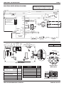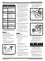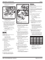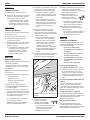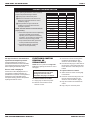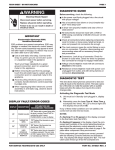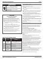
1
TECH SHEET - DO NOT DISCARD
WARNING
Electrical Shock Hazard
Disconnect power before servicing.
Replace all parts and panels before operating.
Failure to do so can result in death or
electrical shock.
PAGE 1
DIAGNOSTIC GUIDE
Before servicing, check the following:
■ Is the power cord firmly plugged into a live circuit with proper
voltage?
■ Has a household fuse blown or circuit breaker tripped? Time
delay fuse?
■ Is dryer vent properly installed and clear of lint or obstructions?
■ All tests/checks should be made with a VOM or DVM having a
sensitivity of 20,000 ohms per volt DC or greater.
■ Check all connections before replacing components. Look for
IMPORTANT
Electrostatic Discharge (ESD)
Sensitive Electronics
ESD problems are present everywhere. ESD may damage or
weaken the electronic control assembly. The new control
assembly may appear to work well after repair is finished, but
failure may occur at a later date due to ESD stress.
■ Use an anti-static wrist strap. Connect wrist strap to
green ground connection point or unpainted metal in
the appliance
-ORTouch your finger repeatedly to a green ground
connection point or unpainted metal in the appliance.
■ Before removing the part from its package, touch the
anti-static bag to a green ground connection point or
unpainted metal in the appliance.
■ Avoid touching electronic parts or terminal contacts;
handle electronic control assembly by edges only.
■ When repackaging failed electronic control assembly in
anti-static bag, observe above instructions.
broken or loose wires, failed terminals, or wires not pressed into
connectors far enough.
■ The most common cause for control failure is corrosion on
connectors. Therefore, disconnecting and reconnecting wires will
be necessary throughout test procedures.
■ Connectors: Look at top of connector. Check for broken or loose
wires. Check for wires not pressed into connector far enough to
engage metal barbs.
■ Resistance checks must be made with power cord unplugged
from outlet.
DIAGNOSTIC TEST
This test allows factory/service personnel to test and verify all inputs to
the electronic control. The basic operation of this test is to notify the
operator with an audible beep every time the status of an input to the
control changes state.
Activating the Diagnostic Test Mode
1. Unit must be in Standby (unit plugged in, display off).
2. Alternately press the More Time ∧, Less Time ∨ touchpads
two times. All LED’s should light and the display should show 88.
If any of these initial conditions are not satisfied, the control will not
enter the test mode.
NOTES:
If a flashing E1 or E2 appears in the display, proceed to the
thermistor test (TEST #3a), page 5.
DISPLAY FAULT/ERROR CODES
DISPLAY
DESCRIPTION
PF
POWER
FAILURE
E1
E2
E3
EXPLANATION AND RECOMMENDED
PROCEDURE
“PF” flashes after a power failure while the
dryer is running. Press Start to continue the
cycle, or press Stop/Cancel to clear the
display.
“E1” flashes if the thermistor is open.
THERMISTOR OPEN See TEST #3a, page 5.
THERMISTOR
SHORTED
USER INTERFACE
OR SOFTWARE
MISMATCH
“E2” flashes if the thermistor has shorted.
See TEST #3a, page 5.
“E3” flashes when there is a keyswitch or
software mismatch. This error code will ONLY
appear when in the Diagnostic Test mode.
See TEST #5, page 6.
If a flashing E3 appears in the display, unplug dryer or disconnect
power. Check the component part numbers of the control panel/
touchpad assembly and the electronic control assembly to see if they
match the part numbers in the chart, page 3. Replace either
component if they are incorrect.
If the component part numbers are correct, plug in dryer or reconnect
power, reenter the Diagnostic Test mode above, and proceed with
the following Console Switches and Indicators Test. The display will
always display the “E3”. The indicator LEDs should go off as the
touchpads are pressed. If the LEDs do not turn off, replace the
touchpad assembly. If all LEDs function properly, proceed to
TEST #5, page 6.
Test Mode Functionality
When the control is in the Diagnostic Test mode, every input change
of state will result in a beep, including the Door Switch, and the
Moisture Sensor (short/open Sensor will result in a beep).
NOTE: A moistened finger or damp cloth may also be used.
Refer to table on next page to test console touchpad.
FOR SERVICE TECHNICIAN'S USE ONLY
PART NO. 8541836
PAGE 2
TECH SHEET - DO NOT DISCARD
CONSOLE SWITCHES AND INDICATORS TEST
PRESS TOUCHPAD
DISPLAY
Heavy Duty
88
88
88
88
88
88
88
88
88
88
88
88
88
88
88
88
88
88
88
88
88
88
88
88
88
88
88
88
8
88
8
88
repeat
Towels/Cotton
repeat
Normal
repeat
Bulky Items
repeat
Casual
repeat
Delicate
repeat
More Dry
repeat
Less Dry
repeat
Timed Dry
repeat
Rack Dry
repeat
Touch Up
repeat
Temp
repeat
Cycle Signal
repeat
Wrinkle Shield
repeat
More Time
repeat
Less Time
repeat
Start
repeat
Stop/Cancel
03 or 05
88
88
CONTROL ACTION
Beep sound. “Heavy Duty” LED is turned off.
Beep sound. “Heavy Duty” LED is turned on.
Beep sound. “Towels/Cotton” LED is turned off.
Beep sound. “Towels/Cotton” LED is turned on.
Beep sound. “Normal” LED is turned off.
Beep sound. “Normal” LED is turned on.
Beep sound. “Bulky Items” LED is turned off.
Beep sound. “Bulky Items” LED is turned on.
Beep sound. “Casual” LED is turned off.
Beep sound. “Casual” LED is turned on.
Beep sound. “Delicate” LED is turned off.
Beep sound. “Delicate” LED is turned on.
Beep sound. Five (5) dryness level LEDs are turned off.
Beep sound. Five (5) dryness level LEDs are turned on.
Beep sound. Five (5) dryness level LEDs are turned off.
Beep sound. Five (5) dryness level LEDs are turned on.
Beep sound. “Timed Dry” LED is turned off.
Beep sound. “Timed Dry” LED is turned on.
Beep sound. “Rack Dry” LED is turned off.
Beep sound. “Rack Dry” LED is turned on.
Beep sound. “Touch Up” LED is turned off.
Beep sound. “Touch Up” LED is turned on.
Beep sound. Six (6) associated LEDs for “Temp” are turned off.
Beep sound. Six (6) associated LEDs for “Temp” are turned on.
Beep sound. LEDs for “Louder”, “Softer”, “Off”, and “Estimated Time Remaining” are turned off.
Beep sound. LEDs for “Louder”, “Softer”, “Off”, and “Estimated Time Remaining” are turned on.
Beep sound. “Wrinkle Shield” LED is turned off.
Beep sound. “Wrinkle Shield” LED is turned on.
Beep sound. Left digit of “88” display is turned off.
Beep sound. Left digit of “88” display reappears.
Beep sound. Right digit of “88” display is turned off.
Beep sound. Right digit of “88” display reappears.
Beep sound. Six (6) associated “Status” LEDs are turned off and relays are activated.
Beep sound. Six (6) associated “Status” LEDs are turned on and relays are deactivated.
Beep sound. All LEDs are turned off.
If pressing any of the above touchpads does not result in the correct action, refer to TEST #5, page 6.
PART NO. 8541836
FOR SERVICE TECHNICIAN'S USE ONLY
TECH SHEET - DO NOT DISCARD
PAGE 3
ELECTRIC DRYER WIRING DIAGRAM
IMPORTANT: Electrostatic (static electricity)
discharge may cause damage to electronic
control assemblies. See page 1 for details.
RED - LINE L2
L1 LINE - BLACK
240 VOLTS
WHITE - NEUTRAL
120 VOLTS
N
DRUM LAMP
BK
NEUTRAL
TERMINAL
LINKED TO
CABINET
BROWN
DL
BLACK
WHITE
P1-5
DOOR
L1
NEUTRAL
P3
USER INTERFACE
MOTOR
(ACTIVE OVERLAY or
ALTERNATE TECHNOLOGY)
PT-1
BLUE
P1-3
P1-1 GRN/YEL
WHITE
BLUE
LT BLUE
THERMAL FUSE
196° F (91° C)
5M
P4
4M
MOIST.
MOIST RTN
HEATER
RELAY
N.O. HEATER +V
MODEL
MODEL RTN
(0.250 TERMINAL)
COM
(0.250 TERMINAL)
HEATER RTN
TEMP.
P2-1
YEL/RED
P2-4
P2-5 RED/WHT
TEMP RTN
P2-6
N.C.
P2-7
BLK
BELT
SWITCH
G
SENSOR
P2-2
BLK
P2-3
CENTRIFUGAL SWITCH
MAIN
2.4-3.6
START
2.4-3.8
3M
2M
1M
6M
DRIVE MOTOR
1/3 H.P.
SENSOR
MOVS
THERMISTOR
10k
±3%
ELECTRONIC
CONTROL
NC
RED
BLACK
THERMAL CUT-OFF
(TCO) 350° F (176° C)
Console
White Blue Light Motor Mounting Heater
Screw
Relay
Relay
Blue
Green/
Yellow
Black
N.O.
G
DOOR
SWITCH
WHITE
P1-2 NEUTRAL
P1-4
BLUE
RED/WHITE
RED
HIGH LIMIT
THERMOSTAT
250° F (121° C)
HEATER
7.8-11.8
Red/ Open
Black White
Black
Open
Yellow/Red
Drum Size:
Drum Speed:
7.4 cubic feet 51.5 ± 3 RPM CW
Start Winding
Main Winding
Black
Date CodeYDDD
P/N XXXXXXX Rev X
COM
Blue
Violet White Green/
Yellow
Red
Red
Electronic Control
PART
NUMBER
COMPONENT
Console Panel/Touchpad Assembly
for White Model:
GEW9868KQ
COMPONENT
Pluggable Drive
Motor Switch
PART
NUMBER
Thermal Cut-Off
3977394
3978825
Thermal Fuse
3392519
Contacts
for Bisque Model:
GEW9868KT
3978825
Heat Element Assembly
3392661
for Graphite Model:
GEW9868KL
3978826
High Limit Thermostat
3390291
Electronic Control Assembly
3978916/
3980061
Drive Motor
8538263
Start
Main Harness
8529981
Thermistor - NTC 10k Ohms
3976615
Run
Door Switch
3406107
Belt Switch
8066134
Wire Harness, Moisture Sensor (w/MOVs) 3406653
FOR SERVICE TECHNICIAN'S USE ONLY
Function
1M 2M 3M 5M 6M
= Contacts closed
Centrifugal Switch (Motor)
PART NO. 8541836
PAGE 4
TECH SHEET - DO NOT DISCARD
TROUBLESHOOTING GUIDE
PROBLEM
POSSIBLE CAUSE / TEST
NOTE: Possible Cause/Tests MUST be performed
in the sequence shown for each problem.
1. Supply connections. See
WON’T POWER UP.
TEST #1 below.
(No response when
2. Check harness connections.
touchpads are
3. Touchpad/LED assembly.
pressed.)
See TEST #5, page 6.
1. See TEST #1 below.
WON’T START
CYCLE.
2. Check harness connections.
1. Check Stop/Cancel
touchpad. See TEST #5,
page 6.
WON’T SHUT OFF. 2. Touchpad/LED assembly.
See TEST #5, page 6.
3. Moisture Sensor.
See TEST #4, page 6.
CONTROL WON’T Touchpad/LED assembly.
ACCEPT
See TEST #5, page 6.
SELECTIONS.
1. Motor. See TEST #2 below.
WON’T RUN.
2. Check harness connections.
1. Heater. See TEST #3,
page 5.
WON’T HEAT.
2. Check harness connections.
3. Check installation.
Thermistor. See TEST #3c,
HEATS IN AIR
CYCLE.
page 6.
SHUTS OFF
Moisture Sensor. See TEST #4,
BEFORE CLOTHES
page 6.
ARE DRY.
TROUBLESHOOTING TESTS
TEST #1
Supply Connections
1. Unplug dryer or disconnect power.
2. Remove the cover plate from the back of
the dryer.
3. With an ohmmeter, check for continuity
between the neutral (N) terminal of the
plug and the center contact on the
terminal block. See figure 1.
N
L1
Terminal Block
5. Access the electronic control without
disconnecting any wiring to it.
6. With an ohmmeter, check for continuity
between the L1 terminal of the plug
(found in step 4) and P1-5 (black wire)
on the electronic control.
Drum Belt
➔ If there is continuity, go to step 7.
➔ If there is no continuity, check that
wires to the terminal block are
mechanically secure. If so, repair or
replace the main wire harness and
test the dryer.
Figure 2. Carefully remove drum belt.
➔ Remove the white connector from the
drive motor switch. See figure 3.
7. Check for continuity between the neutral
(N) terminal of the plug and P1-2 (white
wire) on the electronic control.
➔ If there is continuity, go to step 8.
➔ If there is no continuity, replace the
power cord and test the dryer.
➔ If there is continuity, go to step 4.
PART NO. 8541836
Drive Motor
Switch
White Connector
➔ If there is no continuity and the
mechanical connections of the wire
are secure, repair or replace the main
wire harness.
8. Replace the electronic control.
9. If the dryer still does not operate, replace
the console panel/touchpad assembly.
Figure 3. Remove white connector.
Motor Circuit Test
This test will check the wiring to the motor
and the motor itself. The following items are
part of this system:
–
–
–
–
–
–
Harness connection
Thermal fuse
Belt/belt switch
Motor
Door switch
Electronic control (See ESD
information, page 1)
1. Unplug dryer or disconnect power.
➔ If resistance across P1-3 and P1-4 is
in the range of 1 to 6 ohms, replace
the electronic control.
3. Check the wiring and components in the
path between these measurement points
by referring to the wiring diagram, page 3.
➔ Check the thermal fuse. See TEST
#3b, page 6.
➔ If motor and harness connections
appear good, remove the white
connector from the drive motor switch
and check resistance of motor’s Main
and Start winding coils as shown on
page 3 and in the table below.
NOTE: Main and Start winding coils must
be checked at the motor.
➔ Otherwise, go to step 3.
Figure 1. Plug-to-terminal connections
for electric dryer.
Belt Switch
Pulley
➔ If neither of the plug terminals have
continuity with the left-most contact of
the terminal block, replace the power
cord and test the dryer.
2. Access the electronic control and
measure the resistance across P1-3 and
P1-4.
COM
➔ Access and check the belt switch and
motor. Carefully remove the drum belt
from the spring-loaded belt switch
pulley, gently letting the belt switch
pulley down. See figure 2.
➔ When this is found, go to step 5.
TEST #2
This test assumes that proper voltage is
present at the outlet, and visual inspection
indicates that the power cord is securely
fastened to the terminal block.
Power Cord
Plug
4. In a similar way, check which terminal of
the plug is connected to the left-most
contact on the terminal block and make a
note of it. This will be L1 (black wire) in
the wiring diagram. See figure 1.
WINDING
RESISTANCE
(Ω)
CONTACT POINTS
OF MEASUREMENT
MAIN
2.4–3.6 Ω
4 to 5
START
2.4–3.8 Ω
4 to 3
➔ If the resistance at the motor is
correct, there is an open circuit
between the motor and electronic
control. Check for failed belt switch.
4. Check the belt switch by measuring
resistance between the belt switch wires,
as shown in figure 4, while pushing up
the belt switch pulley.
➔ If the resistance reading goes from
infinity to a few ohms as pulley arm
closes the switch, belt switch is OK. If
not, replace the belt switch.
FOR SERVICE TECHNICIAN'S USE ONLY
TECH SHEET - DO NOT DISCARD
PAGE 5
➔ If belt switch is OK and there is still an
open circuit, check and repair the
wiring harness.
Heater Element
Thermal Cut-Off
TEST #3a
Thermistor Test
NOTE: This test is started with the machine
completely assembled.
High Limit Thermostat
Belt Switch
Wires
The electronic control monitors the exhaust
temperature using the thermistor, and cycles
the heater relay on and off to maintain the
desired temperature.
Begin with an empty dryer and a clean lint
screen.
1. Plug in dryer or reconnect power.
2. Set the following configuration:
Belt Switch Pulley
➔ Door - must be firmly closed.
Belt Switch
➔ Press Timed Dry.
Figure 4. Checking the belt switch.
➔ Press Cycle Signal and select
Louder.
Thermal Fuse
➔ If the Start winding is in question and
the resistance is much greater than
4 Ω, replace the motor.
5. Door Switch problems can be uncovered
in the Test Mode Functionality section,
page 1. If this was not done, the following
can be done without applying power to
the dryer. Connect an ohmmeter across
P1-2 (neutral, white wire) and P1-3
(door, blue wire).
➔ With the door properly closed, the
ohmmeter should indicate a closed
circuit (0–2 ohms).
Thermistor
Figure 5. Thermal Components,
viewed from front.
3. Using an ohmmeter and referring to the
wiring diagram, measure the resistance
from the red wire at the heater relay to
the red wire at the heater.
➔ If the resistance is about 10 ohms, go
to step 5.
➔ If an open circuit is detected, go to
step 4.
➔ If not, replace the door switch
assembly.
TEST #3
Heater Test
This test is performed when either of the
following situations occur:
✔ Dryer doesn’t heat
✔ Heat won’t shut off
This test checks the components making up
the heating circuit. The following items are
part of this system:
–
–
–
–
–
–
–
–
–
Harness/connection
Heater relay
Thermal cut-off
High limit thermostat
Heat element assembly
Centrifugal switch
Thermistor
Console panel/touchpad assembly
Electronic control (See ESD
information, page 1)
4. Visually check the wire connections to
the thermal cut-off, high limit thermostat,
and heater. If connections look good,
check for continuity across each of these
components. Replace the one that is
electrically open.
5. If no open circuit is detected, measure
the resistance between P2-5 (red/white
wire) and P2-6 (black wire) at the
electronic control.
➔ If 6–7 k ohms are measured, replace
the electronic control.
➔ If the resistance is less than 1 k ohm,
replace the thermistor.
Heat will not shut off:
1. Unplug dryer or disconnect power.
2. Access the electronic control, and
measure the resistance between P2-5
(red/white wire) and P2-6 (black wire).
See Electronic Control illustration,
page 3.
Dryer does not heat:
1. Unplug dryer or disconnect power.
➔ If 6–7 k ohms are measured, replace
the electronic control.
➔ Press Start.
3. If after 60 seconds, E1 or E2 flashes in
the display and the dryer shuts off, the
thermistor or wire harness is either
shorted or open.
➔ Unplug dryer or disconnect power.
➔ Check wire connections at the
electronic control and thermistor. If
wire connections are good, remove
the two wires from the thermistor and
check the thermistor.
4. Check the resistance of the thermistor.
NOTE: All thermistor resistance
measurements must be made while
dryer is disconnected from power.
➔ A hair dryer may be used to heat the
thermistor. The table below gives the
resistance values that should be observed for the various temperatures.
THERMISTOR RESISTANCE
TEMP.
°F (°C)
RES.
kΩ
TEMP.
°F (°C)
RES.
kΩ
50° (10°)
19.9
110° (43°)
4.7
60° (16°)
15.3
120° (49°)
3.7
70° (21°)
11.9
130° (54°)
3.1
80° (27°)
9.2
140° (60°)
2.5
90° (32°)
7.4
150° (66°)
2.1
100° (38°)
5.7
160° (71°)
1.7
➔ If the thermistor resistance does not
agree with table, replace the
thermistor.
➔ If the thermistor resistance checks
within normal limits, replace the
electronic control.
➔ If the resistance is much greater than
7 k ohms, replace the thermistor.
2. Remove the toe panel to access the
thermal components. See figure 5.
FOR SERVICE TECHNICIAN'S USE ONLY
PART NO. 8541836
PAGE 6
TEST #3b
Thermal Fuse Test
1. Unplug dryer or disconnect power.
2. Access the thermal fuse by removing the
toe panel. The thermal fuse is wired in
series with the dryer drive motor.
➔ If the thermal fuse is open, replace it.
Check for failed thermistor, shorted
heat element, blocked vent or other
cause of failure. See figure 5, page 5.
TEST #3c
Thermal Cut-Off Test
If the dryer does not heat, check the status
of the thermal cut-off.
1. Unplug dryer or disconnect power.
2. Access the thermal cut-off by first
removing the toe panel.
3. Using an ohmmeter, check the continuity
across the thermal cut-off. See figure 5,
page 5 for location.
➔ If the thermal cut-off is open, replace
the thermal cut-off and high limit
thermostat. In addition, check for
failed heat element, or blocked or
improper exhaust system.
TEST #4
TECH SHEET - DO NOT DISCARD
4. Locate the two metal sensor strips on the
face of the lint screen housing. Bridge
these strips with a wet cloth or finger.
➔ If a beep is heard and a software
revision number is displayed on the
console, the sensor passes the test.
Go to step 5.
➔ If the ohmmeter does not indicate
(infinity) open circuit, go to step 6.
Drum
✔ None of the LEDs light up
✔ A particular group of LEDs does
not light up
✔ A single LED does not light up
✔ No beep sound is heard
✔ No dryer function is activated
✔ E3 error code is displayed
None of the LEDs light up:
1. See Diagnostic Guide section, page 1.
FRONT
2. Visually check that connectors P3 and
P4 are inserted all the way into the
electronic control. If these connections
are good, perform the checks described
in Checking Touchpad Function box,
page 7.
Harness
Connection
Blower
Housing
2. Enter the Diagnostic Test mode. See
procedure, page 1.
NOTE: Over drying may be caused by a
short circuit in the sensor system.
Refer to the Diagnostic Test, page 1 and
activate the Diagnostic Test mode. Check
for the following situations:
when a particular touchpad is
pressed
– Harness/connection
– Metal sensor strips
– Electronic control (See ESD
information, page 1)
➔ Otherwise, go to step 5.
➔ If the problem persists after replacing
the moisture sensor and thermistor,
replace the electronic control.
Touchpad and LED Test
6. Access the moisture sensor by removing
the toe panel. Disconnect the sensor
from the wire harness. See figure 6.
The following items are part of this system:
➔ If this doesn't happen, go to step 4.
10. If moisture sensor diagnostic test
passes, check the thermistor: Perform
TEST #3a, page 5.
TEST #5
➔ Otherwise, measure the resistance
between pins 1 and 2 of connector
P2 on the electronic control. If a
resistance less than 1 MΩ is
measured, inspect the control board
for any debris bridging these pins. If
no debris, replace the electronic
control.
NOTE: Dryer will shut down automatically
after 2½ hours.
3. Open the dryer door. If a beep tone is
heard and a software revision number is
displayed on the console as soon as the
door is opened, a short circuit exists in
the moisture sensor system.
➔ If a resistance less than infinity is
measured, replace this component
(Wire Harness, Moisture Sensor).
5. Unplug dryer or disconnect power.
Access the electronic control and
remove the connector P2. Measure the
resistance across terminals 1 (yellow/red
wire) and 2 (black wire).
This test is performed when an automatic
cycle stops too soon, or runs much longer
than expected.
1. Plug in dryer or reconnect power.
9. Measure the resistance
across each of the outermost
contacts and the center
terminal (ground connection).
➔ If not, unplug dryer or disconnect
power. Access the moisture sensor
wires by removing the toe panel and
disconnecting the sensor wires from
the harness. See figure 6. Go to
step 9.
Moisture Sensor Test
NOTE: This test is started with the machine
completely assembled.
8. Measure the resistance across the pins
of the mating connector. If a small
resistance is measured here, replace this
harness (Main Wire Harness).
A particular group of LEDs does not
light up:
A group or combination of LEDs share a
common electronic connection. If this
connection is open, all of the LEDs in the
group will be disabled. Replace the console
panel/touchpad assembly.
A single LED does not light up:
Figure 6. Disconnect sensor from wire
harness.
7. Measure the resistance
across the outermost
contacts of the cable that
includes the two red MOVs.
➔ If a small resistance is measured,
replace this component (Wire
Harness, Moisture Sensor).
Press the touchpad associated with the LED
several times. If the LED does not light up, the
LED has failed. Replace the console
panel/touchpad assembly.
No beep sound is heard:
If the associated LEDs do light up, it is
possible that the beeper circuit has failed.
Check touchpad functioning (see box, page 7)
before replacing the electronic control.
➔ Otherwise go to step 8.
PART NO. 8541836
FOR SERVICE TECHNICIAN'S USE ONLY
TECH SHEET - DO NOT DISCARD
PAGE 7
CHECKING TOUCHPAD FUNCTION
Before replacing the electronic control, check for
proper touchpad functioning as follows:
■ Unplug dryer or disconnect power.
■ Remove connectors P3 and P4 from the
electronic control (see electronic control
illustration, page 3).
■ Using the table at right, measure the
resistance across the switch when the
touchpad is pressed.
NOTE: The meter must be connected with the
proper polarity.
➔ If the meter responds to the touchpad being
pressed, it indicates the touchpad is
operating. The touchpad is a momentary
connection, so the meter can respond only
while the touchpad is being pressed.
TOUCHPAD
+ LEAD
– LEAD
Heavy Duty
P3-14
P3-11
Towels/Cotton
P3-14
P3-9
Normal
P3-13
P3-11
Bulky Items
P3-13
P3-10
Casual
P3-12
P3-11
Delicate
P3-12
P3-10
More Dry
P3-14
P3-8
Less Dry
P3-14
P3-7
Timed Dry
P3-13
P3-9
P3-10
Rack Dry
P3-14
Touch Up
P3-12
P3-9
Temp
P3-12
P3-8
Cycle Signal
P3-12
P4-2
Wrinkle Shield
P3-13
P3-8
➔ If any switches fail this test, replace the
console panel/touchpad assembly.
More Time
P3-13
P3-7
Less Time
P3-12
P3-7
➔ If all switches test OK, replace the
electronic control (see below).
Stop/Cancel
P3-13
P4-2
Start
P3-14
P4-2
No dryer function is activated when
a particular touchpad is pressed:
If the associated LEDs do light up, it is
possible that the electronic control has failed.
Check touchpad functioning (see box above)
before replacing the electronic control.
ELECTRONIC CONTROL
REMOVAL OR
REPLACEMENT
NOTE: Be sure to perform the Diagnostic
Test before replacing the electronic control.
See page 1.
E3 error code is displayed:
If the E3 error code is displayed, there is a
user interface or software mismatch. It is
possible that a component on the keyswitch or
the electronic control has failed. Check
touchpad functioning (see box above) before
replacing the electronic control.
IMPORTANT: Electrostatic (static
electricity) discharge may cause
damage to electronic control
assemblies. See page 1 for details.
To remove electronic control:
1. Unplug dryer or disconnect power.
2. Remove all connectors from the
electronic control.
3. Remove the console mounting screw,
located near the transformer. See
electronic control illustration, page 3.
4. Push the mounting legs on both sides of
the electronic control toward each other.
Lift the electronic control away from the
bracket.
To replace electronic control:
1. Attach electronic control mounting legs
to the bracket.
2. Insert the console mounting screw into
the hole near the transformer. See
electronic control illustration, page 3.
3. Plug all connectors into the electronic
control.
4. Plug in dryer or reconnect power.
FOR SERVICE TECHNICIAN'S USE ONLY
PART NO. 8541836
PAGE 8
TECH SHEET - DO NOT DISCARD
MANUFACTURED UNDER ONE OR MORE
OF THE FOLLOWING U.S. PATENTS:
4,385,452
4,430,809
4,663,861
4,669,200
4,700,495
4,720,925
4,754,556
4,821,535
4,840,285
4,865,366
4,899,264
4,899,464
4,908,959
5,066,050
5,243,771
5,560,120
5,636,453
5,651,188
5,664,339
D314,261
D314,262
PART NO. 8541836
FOR SERVICE TECHNICIAN'S USE ONLY