1
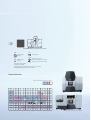
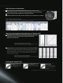
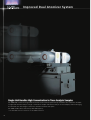
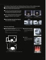
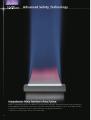
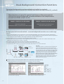
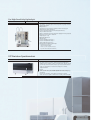
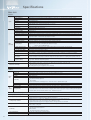
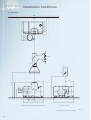
C122-E058G
Atomic Absorption Spectrophotometers
AA- 7000 Series
A A - 7000 Series
Atomic Absorption Spectrophotometers
Reaching Even Greater Heights
Enhanced Flame Analysis
World-Class High-Sensitivity Furnace
Improved Dual Atomizer System
Advanced Safety Technology
System Configuration can Evolve
with Your Needs
The AA-7000 Series can be upgraded by adding units to allow the system to handle the analysis targets.
ASC
*1
AA-7000F Manual Burner System
AA-7000F
AAC
AAC
*3
ASC
GFA
*1
*2
AA-7000F/AAC Auto Burner System
AA-7000F/AAC
ASC
*2
AA-7000G
AA-7000G
GFA-7000A
Major Fields of Application
GFA-7000A Auto Sampler System
Analysis Sensitivities
AA-7000 Series supports a wide range of
analysis applications.
Concentration limit of detection
Environment
Seawater, river water, effluent,
sludge, air-borne dust
Furnace
Flame
(ppm)
(ppb)
H
He
Li Be
B
C
N
O
F Ne
Metals, minerals, glass,
ceramics, IC chips
Na Mg
Al Si
P
S
Cl Ar
Petroleum, Chemicals, Polymers
Rb Sr
Petroleum, oil, catalysts,
chemical products, biodiesel
Cs Ba La Hf Ta W Re Os Ir Pt Au Hg Tl Pb Bi Po At Rn
Metals, Semiconductors, Ceramics
K Ca Sc Ti
Y
V Cr Mn Fe Co Ni Cu Zn Ga
a Ge As Se Br Kr
Zr Nb Mo Tc Ru Rh Pd Ag Cd In Sn Sb Te
I
Xe
Fr Ra Ac
Medical, Biology, Pharmaceuticals
Blood, animals, plants,
drugs, food products
Ce Pr Nd Pm Sm Eu Gd Tb Dy Ho Er Tm Yb Lu
Th Pa U Np Pu Am Cm Bk Cf Es Fm Md No Lr
* May differ according to coexisting substances in the sample.
4
AUTO
AA-7000F/AAC Dual Atomizer System
ASC
AAC
Auto Atomizer
Changer
Autosampler
AUTO
GFA
Graphite Furnace
Atomizer
Dual Atomizer System
Automatic adjustment of atomizer
Automatic serach of burner height
*1 Requires ASC stand kit.
*2 Requires ASK-7000.
*3 Automatic burner height search function can be used.
AA-7000F/AAC equips with AAC as standard.
Flame Selection
Flame and Measurement Procedures
Air-C2H2 N2O-C2H2 HVG MVU
H
He
Li Be
B
C
N
O
F Ne
Na Mg
Al Si
P
S
Cl Ar
K Ca Sc Ti
Rb Sr
Y
AA-7000F Flame Model
V Cr Mn Fe Co Ni Cu Zn Ga Ge As Se Br Kr
Zr Nb Mo Tc Ru Rh Pd Ag Cd In Sn Sb Te
I
Xe
u Hg Tl Pb Bi Po At Rn
Cs Ba La Hf Ta W Re Os Ir Pt Au
Fr Ra Ac
Ce Pr Nd Pm Sm Eu Gd Tb Dy Ho Er Tm Yb Lu
Th Pa U Np Pu Am Cm Bk Cf Es Fm Md No Lr
AA-7000G Furnace Model (with options attached)
5
Enhanced Flame Analysis
Monochromator
Detector
Chopper mirror
Reference beam
D2 lamp
Sample beam
Beam splitter
Burner head (or graphite tube)
Hollow cathode lamp
Double-Beam Optics and Stable Hardware Achieve Superior Stability
The AA-7000 Series incorporates newly developed 3D double-beam optics.
The optical system has been designed to produce its maximum performance for each measurement method through
optimal adjustment of the light beam and light beam digital filter, and by using optical components that restrict light
losses.
6
Advantages of the Double-Beam System
High sensitivity
The graph shows the results of
measurements on 2 ppm copper (Cu)
conducted over at least one hour.
(The plot shows mean values for 11
repeated measurements.) Over the
course of more than 600
measurements, the instrument
achieved a relative standard
deviation within 1%.
The graph shows the direct
measurement results for 0.1
ppm lead (Pb).
Absorbance
Long-term stability
A
b
s
Measurement time
Conc(ppm)
Data Showing Long-Term Stability for
Flame Cu Measurements
0.1 ppm to 0.4 ppm Calibration Curve for Lead (Pb)
Support for Developing Analytical Conditions
Automatic gas flow rate optimization
Automatic searching for optimal fuel gas flow rate (Japanese Patent 2099886). It is important
to determine the optimal gas flow rate for the flame when using an organic solvent or after
changing the burner height. The AA-7000F Series automatically optimizes the gas flow rate
by measuring the changes in absorbance between a blank and a standard sample. The
difference between the two is displayed on the screen. The gas flow rate achieving the
highest sensitivity is detected and this value is automatically set as the gas flow rate value.
Automatic burner height optimization (AA-7000F/AAC)
The absorption sensitivity for flame analysis is also affected by the burner height. This results
from variations in the flame temperature due to the burner height. The flame temperature is
also affected by the matrix components. AA-7000F/AAC adjusts the burner height in 0.5 mm
steps to automatically search for the optimal conditions.
AA-7000F enables above function by AAC-7000 (option).
Optional Autosampler Reduces Analysis Workload
Low carryover
Great care must be taken to avoid carryover during flame analysis. The new ASC-7000
autosampler rinses the nozzle at the rinsing port on the overflow mechanism after each
sample measurement is complete. This ensures 10-4 max. carryover during the
measurements of multiple samples. The graph shows the results of consecutive analyses
of 10 ppm, 20 ppm, and 50 ppm sodium (Na) standard solutions in the EMISSION mode.
No carryover could be detected when measuring the 10 ppm standard sample
immediately after the measuring the 50 ppm Na standard sample.
Discharge
Conventional method Overflow method
Data showing low carryover
Trace Sample Analysis Using Micro Sampling
Micro sampling
At least 1 mL (1000 µL) volume of a liquid sample is required for the continuous intake of
sample during normal flame analysis. With micro sampling, however, approximately 50 to 90
µL of sample is injected in one shot into the flame and quantitation is based on the height
and area of the peak signal obtained. This method offers the advantages below.
Advantages
. Permits analysis of small sample volumes
. Multi-element analysis of small sample volumes
. No blockage of burner slot with samples having a high salt concentration
. Synchronized with the autosampler for auto-dilution measurements
Sampling port
Sampling port
Solenoid
valve
(closed)
Solenoid
valve
(opened)
1. Sample injected into
micro sampling port.
2. Solenoid valve opens to inject sample
in one shot into the flame.
* Synchronization with the autosampler requires the optional micro sampling kit.
Example of micro sampling analysis
Examples of the measured waveforms (overlaid) and calibration curve for micro
sampling analysis are shown to the right.
A 2-ppm Cu standard solution was prepared by auto-dilution using the autosampler.
The autosampler can also be used to conduct dilution measurements of the sample.
(Injection volume: 90 µL)
7
World-Class High-Sensitivity Furnace
Achieves World-Class Lower Limits of Detection
Advances in optics and a new graphite furnace design achieve improved
lower limits of detection for furnace analysis (comparison with previous
Shimadzu models).
This superb analysis performance is possible in all fields.
8
Enhanced Sensitivity due to Graphite Furnace
Previous
New
Pb 0.08ppb
0 . 0 5 ppb
Mn 0 . 0 2 p p b
0 . 0 1 ppb
High-Performance Autosampler
Mix and inject up to four sample types (diluted solution, standard solution,
sample, matrix modifier, etc.). (Of course, unmixed samples can also be injected.)
Select a fluororesin tube or pipette tip as the injection nozzle.
Automatic dilution and re-analysis if the calibration curve concentration is exceeded.
Example of Automatic Dilution and Re-Analysis
Analysis of cadmium (Cd): The maximum concentration of the calibration curve has been set to 1ppb. At 1.8ppb, the sample of [003] has exceeded the
maximum concentration. As a resultit has been automatically diluted by 4 times and re-measured.
High-Sensitivity Application Data (Analysis of Selenium (Se))
Independent control of the gas flow through the graphite tube during
atomization achieves extremely high-sensitivity measurements.
(Japanese Patent 2067563)
Measurement Example Showing High Sensitivity
Analysis of 0 to 5 ppb selenium (Se): Sensitivity is adequate for 1 ppb measurements.
(20 µL injected volume, Pd modifier, pyro-coated graphite tube)
Digital temperature control and electronic gas flow control enhance stability
Combination of a high-sensitivity optical sensor and unique digital temperature control
technology achieves highly accurate temperature control in all temperature regions from
drying to atomization. An electronic flow controller can precisely control the inner gas
flow rate in 0.01 L/min units. These control techniques significantly enhance both the
sensitivity and the data stability.
Measurement Example Showing High Stability
Analysis of 0.5 ppb lead (Pb): Approx. 5% relative standard deviation after 5 repeated
measurements is adequate for quantitative analysis.
Selecting the Graphite Tube
High-density graphite tube
(P/N 206-50587)
Can be used for all elements. Especially
effective for low-boiling point elements
(Cd, Pb, Na, K, Zn, Mg, etc.).
Pyro-coated graphite tube
(P/N 206-50588)
Effective for elements that readily form
carbides (Ni, Fe, Cu, Ca, Ti, Si, V, Mo, etc.).
Platform tube
(P/N 206-50887-02)
Restricts chemical interference due to
coexisting substances. Effective for the
analysis of environmental samples and
biosamples, such as sea water and
industrial waste.
* Depending on the state of the sample, some other combinations may be appropriate.
9
Improved Dual Atomizer System
Single Unit Handles High Concentration to Trace Analysis Samples
AA-7000F/AAC creates an integral burner and furnace that remains permanently installed in the combustion chamber.
It supports both flame analysis of high concentration samples and furnace analysis of trace samples, without changing
the atomizer unit. The integral construction with the atomizer saves space.
AA-7000F enables above function by AAC-7000 (option).
* The AAC-7000 cannot be attached to an AA-7000G instrument.
10
New Atomizer Design Permits Easy Switching Between Flame and Furnace Measurements
The new drive mechanism halves the switching time between flame and furnace measurements
(comparison with previous Shimadzu models).
The atomizer unit is switched automatically by software
operation. No troublesome replacement of the atomizer
unit is required. No need to disconnect pipes or wires.
In case of the flame measurement of high-concentration
sample, offsetting the burner head from the light axis,
instead of angle adjustment, allows to adjust the
sensitivity.
Flame measurement: Burner head
intersects the light axis (red line).
Furnace measurement: Furnace
intersects the light axis (red line).
A single autosampler can be used for both flame and
furnace measurements. Simply slide it left or right. No
need to purchase two autosamplers.
Flame measurement
Furnace measurement
Slim, Easy-to-Use Design
Smallest footprint for a full system
Easily attach an autosampler
The system with a dual atomizer fits into a 960 mm width
(including power supply for the graphite furnace atomizer),
achieving the world's smallest installation footprint* for a full
system.
Direct connection of the autosampler
to the AA instrument minimizes the
installation footprint and simplifies
maintenance.
* Shimadzu in-house investigation. Current as of November 2008.
Lamp house
Just slide the cover to the side for
easy replacement of the hollow
cathode lamps through the large
opening.
AA-6300
AA-7000F/AAC Dual Atomizer System
* Dimensions do not include ASC-7000. Height (H) does not include protrusions.
11
Advanced Safety Technology
Comprehensive Safety Functions in Every System
Safety is an extremely important consideration for flame atomic absorption spectrophotometers using acetylene gas.
The AA-7000 Series instruments are the first* ones in the world fitted with a vibration sensor as standard. They also
incorporate a comprehensive range of safety mechanisms, including gas leak detectors.
* Shimadzu in-house investigation. Current as of November 2008.
12
Safety Functions for Flame-Specification Instruments
World first! –– flame extinguished automatically by vibration sensor
The flame is automatically extinguished when the new built-in sensor detects vibrations.
Instruments are completely safe during severe shaking caused by earthquakes.
Multimode automatic gas leak check
The fuel gas pipes inside the instrument gas controller are automatically
checked for gas leaks when the power is turned on and when the flame is
extinguished. Should a gas leak be detected, a warning buzzer sounds and a
warning is displayed on the screen.
Automatic flame ignition and extinguishing
Flame ignition and extinguishing operations are extremely simple. The
Air-C2H2 flame priority ignition mechanism prevents flashback.
Automatic Air-N2O switching system with acetylene flow-rate monitor
After the ignition of an Air-C2H2 flame, the flame automatically switches to
an N2O-C2H2 flame.
If the C2H2 flow rate does not increase due to solenoid valve trouble, for
example, switching to the support gas is disabled to prevent flashback.
Pressure monitor prevents flashback
The connected options and operation of safety mechanisms are
checked during instrument initialization.
Automatic gas shut-off by flame monitor
Sudden power interruption detection and re-ignition safety measures
Mechanism to prevent misuse of the burner
Drain tank level monitor
Safety Functions for Furnace-Specification Instruments
Cooling water flow rate monitor
Argon gas pressure monitor
Furnace cooling check
Overcurrent protection unit (double-checked by circuit protector and optical sensor)
Safety-Conscious Design
Flame-retardant materials
Safe ignition switches
UL 94V-0-rated flame-retardant materials
are used for the instrument external
covers and atomizer unit. This superior
design pays due consideration to safety.
The switches perfectly fit finger contours and are positioned
near the window.
To prevent inadvertent operation, both switches must be
pressed simultaneously to start ignition.
Durable pipes and reliable couplings
Clear window
All pipes are selected for durability and
used with highly reliable couplings.
The large window permits observation of the flame, and the
burner can be easily accessed through the large opening.
The window closes when released to eliminate the chance
of it being left open.
13
Dual-Background Correction Functions
The optimal background correction methods are installed as standard:
high-speed self-reversal method (SR method) and deuterium lamp method (D2 method).
These functions can correct for spectral interference in flame measurement.
Selecting the optimal background correction method for each sample ensures
accurate and reliable analysis results.
Samples suitable for the SR method
Samples suitable for the D 2 method
Samples with a complex matrix
Purified water, tap water, environmental water, etc.
(Containing a large quantity of a specific element as the main component)
Samples with a relatively simple matrix
SR (high-speed self-reversal) method –– accurate background correction over a wide range
Features
1. High-speed self-reversal (SR) correction is generally more accurate than deuterium lamp (D2) correction. As both atomic absorption and background
absorption can be measured using a single lamp, the correction errors due to light-axis misalignment are extremely small. This is ideal for the quantitation
of trace components in a matrix exhibiting complex background absorption, such as bio-samples and metals.
2. Permits background correction over the entire wavelength range from 185 nm to 900 nm.
3. This method can correct for spectral interference due to neighboring lines that can occur when a resonance line for another element exists near the
analytical line for the target element. (See table on next page.)
4. As no polarizer is used, measurements are possible with low light losses and a high S/N ratio.
5. The rapid lamp lighting permits accurate measurement unaffected by emission noise in the atomizer.
* Hollow cathode lamp L-2433 is required to use the SR method. Hollow cathode lamp L-2433 can also be used for the D2 method.
IH spectrum
Principle
Background absorption
Background
Lamp current
Atomic absorption
Atomic
absorption
IH
Wavelength
IL
Wavelength
Atomic
Absorption absorption
layer
IL spectrum
Background
Time
Atomic absorption
(Lamp energy)
(Sample measurement)
(Energy component ratio)
A small current IL (approx. 10 mA) and a large current IH (approx. 500
mA) are alternately passed through the hollow cathode lamp. The
lamp emission spectrum when the large current flows has a depression
in the center (self-reverse), due to self-absorption of the large number
of sputtered atoms in the atom cloud, as shown in the diagram to the
left. No significant atomic absorption is apparent and background
absorption mainly occurs. Conversely, the lamp emission spectrum
when the small current flows comprises a single narrow peak resulting
from both atomic absorption and background absorption. By
determining the difference between the two types of absorption, it is
possible to accurately correct for the background absorption and
measure the true atomic absorption.
Examples suitable for SR method (where differences result between SR and D2 methods)
Example: Measurement of trace levels of zinc in iron (analysis of Zn in Fe solution)
BGC-SR method
Atomic absorption signal
Background signal
BGC-D 2 method
Zn 0.25ppm
Atomic absorption signal
Background signal
Zn 0.50ppm
Fe 0.1%
Fe 0.5%
Fe 0.5%
Zn 0.25ppm
Fe 0.5%
Zn 0.5ppm
Fe 0.75%
The identical 0.5 ppm Zn solution is accurately corrected to
the same absorbance at (2) and (6).
14
Due to inadequate correction, the absorbance is higher at
(6) than at (2) for the identical 0.5 ppm Zn solution.
Zn 0.3ppm
Examples of elements and wavelengths causing spectral
interference problems due to neighboring lines
Measured Element Analytical Line (nm) Coexisting Element Absorption Line (nm)
Al
309. 28
Mg
3 0 9 .3 0
As
193. 76
Fe
1 9 3 .7 3
Ca
422. 67
Fe
4 2 2 .6 4
Cd
228. 80
Ni
2 2 8 .8 4
Cu
324. 75
Fe
3 2 4 .7 3
Ga
294. 36
Ni
2 9 4 .3 9
Mg
285. 21
Fe
2 8 5 .1 8
Ni
232. 00
Fe
2 3 2 .0 4
Pb
217. 00
Fe
2 1 6 .9 5
Sb
217. 58
Fe
2 1 7 .5 5
Se
196. 03
Fe
1 9 6 .0 5
Si
251. 61
Fe
2 5 1 .6 9
Zn
213. 856
Fe
2 1 3 .8 5 8 9
The SR method is suitable for samples containing elements that cause
problems with spectral interference, as shown in the table to the left.
D2 (deuterium lamp) method –– highly sensitive background correction
Fe
Features
1. Detection sensitivity is superior to the SR method. Therefore, this method is suitable for the analysis of samples with a simple matrix requiring high
sensitivity, such as the measurement of trace levels of impurities in ultrapure water or environmental analyses.
2. As the lighting frequency is higher than with the SR method, it can eliminate noise due to emission components of the flame or graphite tube to permit
accurate atomic absorption measurements.
3. The original hollow cathode lamp can be used.
D2 lamp spectrum
Principle
Background absorption
Atomic absorption
Hollow cathode lamp spectrum
The deuterium lamp method involves lighting the hollow cathode lamp and the
deuterium lamp alternately at high speed. After separation by the monochromator,
the light from the deuterium lamp has a bandwidth from 0.1 to 5 nm. Therefore, an
atomic absorption with a line width of only about 1/1000 nm is almost unobservable
compared to the background absorption due to wide-bandwidth molecular
absorption. However, as the light from the hollow cathode lamp has approximately
the same bandwidth as the atomic absorption band, the total of the atomic
absorption and the background absorption can be observed. With the deuterium
lamp (D2) method, light from both sources passes through the atomizer. The
difference in absorbance is determined to conduct background correction.
Atomic absorption + background absorption
Examples suitable for D2 method (where no difference results between SR and D2 methods)
Example: Measurement of trace levels of lead in 2% NaCl solution by molecular absorption (analysis of Pb in 2% NaCl solution)
BGC-D 2 method
BGC-SR method
Background signal
Atomic absorption signal
Spike
0ppb
2ppb
4ppb
Spike
0ppb
2ppb
4ppb
It can be seen that the sensitivity is higher with the BGC-D2 method.
15
Clear, Easy-to-Use Software
Features of the WizAArd Software
The WizAArd software used with the AA-7000
AA 7000 runs under Windows 7/ Vista/XP
Vista/XP.
p That
Tha Even a Novice Can Do It.
Wizard Functions Make Setting the Conditions So Simple
Just set the measurement conditions using WizAArd to
complete the general settings.
The initial settings can also be completed simply
by following the Wizard procedures.
Start Wizard.
Select element.
Set calibration curve and sample parameters.
Set monochromator parameters.
Connect to instrument.
Measurement Screen Layout Shows Measurement Status at a Glance
Measured element
Real-time signal monitor
MRT (Measured Results Table)
The worksheet shows sample names,
absorbance, concentrations,
and correction calibration results.
L
Lamp
Hi t
History
Function
F
ti Assists
A i t with
ith Lamp
L
Management
M
t
The accumulated operation time for each lamp displayed on the lamp
registration screen assists with lamp service life management. Multiple
lamps for the same element are differentiated using lamp IDs.
16
Signal profile display
Calibration curve display
Software
Sof
ftware Provides Comprehensive Information Displays and Flexible Settings
Identical software operation for flame and furnace measurem
measurements
Even if the
h calibration
lib i curve is
i created
d after
f sample
l measurements,
concentration calculations can be conducted on past data. This
allows trial measurements to be directly used as actual
measurements.
Extrapolation of calibration curve range. If the sample concentration
exceeds the calibration curve range, additional measurements can be
performed on standard solutions to re-calculate the concentration.
Use existing calibration curves for measurements. Useful for sample
concentration order checks and for checking the instrument
sensitivity.
One-touch re-measurement operation. No need to repeat the
measurement from the beginning.
Create and save multiple calibration curves on a single worksheet.
Select the appropriate calibration curve for the sample concentration
and composition.
Combining a high-performance autosampler simplifies
p
advanced settings
advan
g
Real-time drying and ashing progress display for furnace
measurement
A higher temperature cleaning operation than the cleaning stage
can be added for each measurement. This reduces the graphite tube
memory effect. Tube deterioration is reduced by minimizing the
cleaning operations.
Add optional autosampler rinsing operations to ensure adequate
rinsing of the autosampler after completing the measurement of
high-concentration samples.
Set up sample dilution and spike-and-recovery tests on the same
screen.
Overlay function allows size and shape comparison of peak profiles.
Large-volume injection permits high-sensitivity measurements.
Precision control of drying and ashing temperatures reduces analysis
time.
1
17
Supports System Management andAccuracy
FDA 21 CFR Part 11 Compliance
A combination of enhanced WizAArd software with Shimadzu's network-compatible CLASS-Agent data
management software supports FDA 21 CFR Part 11 Compliance.
WizAArd used alone provides comprehensive system policy setting, user management, log browser, audit trail,
and electronic signature system management functions.
Hardware validation software installed as standard.
Comprehensive
Comp
prehensive Data Manag
Management
gement Functions
System Policy
CLASS-Agent (Option)
The system policy settings allow advanced
password and lockout settings. The levels
can be set in stages from "unrestricted"
to "Part 11 compatible".
Connection to CLASS-Agent permits
efficient, long-term database
management of large amounts of analysis
data.
data
Userr Management
Use
Mana
Managem
gement
ent
User management restricts the users of
the system. It registers each user to
determine how each one uses the
software.
18
Log Br
Brows
Browser
owser
er
The log browser easily displays a variety of logs to check the
system modification history and other log information.
Management
Accuracyy Management
Managgement (Q
((QA/QC)
A/QC) Functions Permit User Level Management, Audit Trail, and Electronic Signatures
QA/QC compatibility
The QA/QC functions permit accuracy
management.
Hardware validation software installed ass standard
stand
dard
d
The hardware validation software makes it simple to evaluate the instrument
performance. When combined with the autosampler, it automatically determines
the wavelength accuracy, noise level, baseline drift, absorbance and repeatability,
and prints out the results of comparison with the pass criteria.
* Data from all Shimadzu analytical instruments can be centrally managed by CLASS-Agent.
19
Standard Parts / PC / Software
Common to All AA-7000 Series Models
Part Name
Quantity
P/N
Cable set
1
071-60821-08 (120 V), 071-60825-51 (230 V)
Cards (set of 10)
1
206-52046-91
Instruction manual
1
206-97176
Safety inspection sheet (safety instruction)
1
206-97225
Declaration of conformity, explanatory notes (ISO-9001)
1
228-30164
Warranty label
1
037-70238-01
Registration form
1
221-40500
Serial number label
3
206-57770
* The PC, monitor, printer, hollow cathode lamps, high-temperature burner head, pressure regulator and compressor are not included in the standard configuration.
AA-7000F, AA-7000F/AAC Standard Parts List
Part Name
Quantity
P/N
Hose ASSY (for air supply)
1
206-50389-91
Hose ASSY (for C2H2 gas supply)
1
206-50389-92
Hose clamp (16 mm)
2
037-61019
Cleaning wire
1
201-79229-01
Sampling tube (PTFE)
2
204-05899-01
Sampling tube (for organic solvent samples)
1
206-50772-91
Polyethylene tubing, No. 3
1 (0.3 m)
200-31328-01
Polyethylene tubing, 8 × 1 (drain tubing)
1 (2.4 m)
016-43201-02
Drain ASSY
1
206-77413-41
Grease (in cup)
1
206-50442-91
Funnel
1
206-77243-92
Declaration of conformity, English version (ISO-9001)
1
206-84934-66/-68
Inspection report
1
206-77551-02/-22
AA-7000G Standard Parts List
Part Name
Quantity
P/N
Declaration of conformity, English version (ISO-9001)
1
206-84934-67
Furnace mounting plate
1
206-77704
Inspection report
1
206-77551-12
* GFA-7000A is not included in the standard configuration.
Personal Computer / Monitor
Operating system
Microsoft Windows 7 Professional (32 bit) Vista Business or XP Professional
CPU
Intel ® Celeron 420 (1.60 GHz) or higher
RAM
1 GB or higher (Vista) or 512 MB or higher (XP)
Monitor
XGA (1024 × 768 dots) or higher
Storage device
One CD-ROM drive (for installing software) Requires 60 MB min. hard disk space for installation
I/O port
One serial port (for AA control)
* Windows is a registered trademark of Microsoft Corp., U.S.A.
20
Optional Accessories
For Flame Analysis
Part Name
High-temperature burner head
P/N
206-77530-91
Remarks
Made of pure titanium. Air-cooled. 5 cm slot for N2O-C2H2 flame
. Extremely corrosion-resistant
. Can also be used for Air-C H flame.
2
Flow meter kit
206-77617-41
2
Float-type flow meter for support gas
Dimensions: 250 W × 130 D × 170 H mm
Sample platform
206-77655-91
Vial mounting platform: 220 W × 95 D mm
Vial positions: 5-step switching
Air compressor
208-91753-91
100 VAC, 50/60 Hz, with mist separator
Low-noise air compressor
208-91750-36
100 VAC, 50/60 Hz, with mist separator
Mist separator kit
206-52458-91
Required if using an air compressor other than above.
YR-71 compressed gas regulator
040-72020-01
For C2H2
MAF-85S compressed gas regulator
040-72019-11
For dinitrogen oxide gas
Micro sampling kit
206-77540-91
Required to use the flame micro sampling method. ASC-7000 and
ASK-7000 (or ASC stand kit) are also required.
O-ring set
206-77620-92
O-ring set for organic solvents
For Furnace Analysis
Part Name
GFA-7000A graphite furnace atomizer
P/N
206-77777-XX
Remarks
ISpecifications
Heating control system: Drying: Digital current control
(with automatic temperature calibration function)
Ashing, atomization: Digital temperature control via
optical sensor
Heating temperature range: Ambient to 3000 °C
Inner gas type: Dual automatic switching type
Inner gas flow rate: 0 to 1.50 L/min, 0.01 L/min increments
Ar gas: 3.5 L/min max.
Cooling water: Cooling water circulation unit or tap for process water
Water temperature: 10 to 30 °C, flow rate: 0.6 to 1.5 L/min
* Separately order the parts below.
Provides viewing inside the graphite tube.
Including Video View Software (CD-ROM)
Graphite Furnace Camera GFA-TV
206-52950-41
High-density graphite tube
206-50587-11
Pyro-coated graphite tube
206-50588-11
Platform tube
206-50887-02
MAF-106S compressed gas regulator
040-72019-21
For Argon gas
CA-1115A-1 cooling water circulation unit
044-01813-01
For cooling GFA, 100 VAC, 1100VA, 50/60 Hz
Select one of the three types of graphite tubes according to the aim of the analysis.
Parts for cooling water connections
Cooler connection kit
206-84373-41
For connecting GFA and CA-1115A-1
Cooling water tube ASSY
206-51028-41
Connecting tubes when using tap water to cool GFA
Regulator ASSY
206-86147-41
Decompression valve when using tap water to cool GFA
Autosampler
Part Name
ASC-7000 autosampler
P/N
206-77600-XX
Remarks
ISpecifications
System: Flame / furnace
Function: Zero-point detection, auto rinse, auto diagnosis, random access
Maximum reagent / sample positions: Reagents: 8 positions, samples: 60 positions
* Separately order the parts below.
For flame analysis
For furnace analysis
ASC stand kit
206-77650-41
Required to mount ASC-7000 to conduct flame analysis only.
ASK-7000 extension unit for furnace analysis
206-77550-41
Permits both flame and furnace analysis.
Nozzle ASSY, HVG
206-67563
Required to use ASC-7000 and HVG-1.
21
Optional Accessories / Related Products
Dual Atomizer System
Part Name
P/N
AAC-7000 auto atomizer changer
Remarks
206-77701-41
Required to add GFA-7000A to AA-7000F to conduct furnace analysis.
Permits automatic burner position setting for flame analysis with AA-7000F.
Hollow Cathode Lamps
Part Name
P/N
Remarks
L-233 series
200-38422-XX
L-2433 series
200-38456-XX
For SR method
Other Accessories
Part Name
P/N
Analog output cable
Remarks
206-77707-91
Used for analog output to a pen recorder, etc.
One cable required per channel (atomic absorption/energy signal, background signal).
For High-Sensitivity As, Se, Sb Analysis
Part Name
P/N
HVG-1 hydride vapor generator
Remarks
206-17143-XX
Environmental standards prescribe the hydride generation method as one
method of As, Se, and Sb analysis.
1. Used with the AA-7000 Series, HVG-1 permits the rapid and accurate
quantitation of elements such as As, Se, Sb and Hg at several-ppb levels.
2. Used with an ASC-7000 autosampler, it permits the automated serial
analysis of up to 60 samples.
* Nozzle ASSY, HVG (P/N: 206-67563) is required to use HVG-1 with an ASC-7000 Series
instrument. Order separately.
ISpecifications
Measurement method: continuous flow
Sample consumption: 0 to 7 mL/min, variable
Reagent consumption: 0 to 2.5 mL/min, variable
Atomizer: Heated absorption cell (heated by Air-C2H2 flame in standard system)
Carrier gas: Ar pressure: 0.32 MPa, consumption: 70 mL/min
Power requirements: 100, 120, 220, 230, 240 VAC, 35 VA, 50/60 Hz
Dimensions: 340 W × 220 D × 200 H mm
Weight: Approx. 9 kg
IStandard Major Items
Hydride vapor generator, absorption cell (P/N: 206-77607)
Reagent bottles (P/N: 206-58792-40/-42), gas hose, drain tube, etc.
For Higher Sensitivity with the Hydride Generation Method
Part Name
P/N
SARF-16C atomic muffle furnace
(Electronic Cell Heater)
Remarks
208-97249
1. This dedicated furnace permits higher sensitivity measurements using the
hydride vapor generator than the flame heating method.
2. The temperature controller provides optimal control of the quartz cell
temperature.
3. Good temperature reproducibility. Extends cell life by preventing
damage due to overheating.
* The atomic muffler cannot be used when an AAC-7000 is installed on an AA-7000F/AAC
or AA-7000F.
Temperature
sensor
Te
Cell heater
he
HVG-1 hydride vapor generator
Controller
Atomic absorption
spectrophotometer
ISpecifications
Furnace
Dimensions: 170 W × 110 D × 110 H mm
I.D.: ø25 × 170 mm
Heater: PYROMAX DS
Controller
Operational temperature range: Ambient to 1100 °C
Temperature regulation range: ±2.5 °C
Load capacity: 1000 W max.
Power requirements: 100 VAC, 400 VA, 50/60 Hz
Computer
* Use a stepdown transformer in regions that do not have a 100 V power supply.
Mounting adaptor
22
206-52135-91
For AA-7000F
206-83755-91
For AA-7000G
For High-Sensitivity Hg Analysis
Part Name
P/N
MVU-1A mercury vaporizer unit
206-58780-XX
Remarks
This mercury vaporizer unit permits analysis using the reduction
vaporization –– atomic absorption method. It permits easy, high-sensitivity
water quality analysis.
ISpecifications
Vaporization method: reduction vaporization with a reducing agent
Measurement method: recirculation
Flow cell: optical path length 100 mm (with quartz window)
Sample volume: 250 mL max.
Exhaust contamination prevention: adsorption trapping in mercury trap bottle
Dimensions: 310 W × 357 D × 288 H mm
Weight: Approx. 10 kg
IStandard Major Items
MVU-1A unit: 1
Reaction vial (P/N: 200-93018-01): 5
Reaction vial lid (P/N: 204-21989): 2
Stirrer tip (P/N: 046-00617-06): 10
Mercury trap bottle (P/N: 206-58777-42): 1
* Separately order the parts below.
s'ASFLOWCELL0.
s(OLDERFORGASFLOWCELL0.
s(GHOLLOWCATHODELAMP0. ICP Emission Spectrometers
ICPE-9800 Series
Remarks
ICPE-9800 Series of simultaneous ICP atomic emission spectrometers offer
the superior accuracy necessary to simultaneously and quickly analyze
multiple elements regardless of their concentration levels. They also feature
user-friendly software that makes analysis easy. Various assistant functions
enable easy optimization of methods and a simpler, more efficient
analytical workflow.
Features
Eco mode, Mini-torch system, Vacuum spectrometer: reduce the argon gas
consumption
Vertical torch orientation: ensure stable low-maintenance analyses
1-inch CCD detector: capable of simultaneous recording of all wavelengths
23
Specifications
Main Unit
Basics
Optics
Wavelength range
185.0 to 900.0 nm
Monochromator
Aberration-corrected Czerny-Turner mounting, Number of grating grooves: 1800 lines / mm, Focal length: 300 mm
Bandwidth
0.2, 0.7, 1.3, 2.0L nm (4-step automatic switching)
Detector
Photomultiplier tube
Optics
Optical double-beam
Background correction method
BGC-SR (high-speed self-reversal method) (185.0 to 900.0 nm)
BGC-D2 (D2 lamp method) (185.0 to 430.0 nm)
Number of HC lamps
6-lamp turret, 2 lamps simultaneously lit (1 for measurement, 1 warming up for next measurement)
Lamp mode
EMISSION, NON-BGC, BGC-D2, BGC-SR
Software requirements
Microsoft Windows 7 Professional / Vista Business / XP Professional
Parameter setting
Wizard method
Measurement mode
Data
processing
..
Flame continuous method, flame micro sampling method, furnace method, flame emission method
Concentration computation mode
. Calibration curve method (select primary, secondary, tertiary) . Standard addition method, simple standard addition method (primary expression)
Repeat analysis
Up to 20 repetitions. Mean value, standard deviation (SD) and coefficient of variation (RSD) display
Automatic exclusion of deviant values by setting SD and %RSD
Baseline correction
Automatic correction of baseline drift by offset correction in peak height / peak area modes.
Signal processing segment setting
Signal processing segments can be changed in peak height / peak area modes.
Sensitivity correction
Automatic calibration curve correction function using sensitivity monitoring
Analog output
2 channels (atomic absorption/energy signal, background signal)
Output range: 5.0, 2.5, 1.25, 0.625 Abs./V (each settable in 4 stages)
Fixed at 1 V F.S. in EMISSION mode.
Tabular data processing
Final concentration calculations based on sampled volume, dilution rate, fixed volume, and factor inputs
Recall of parameters
Template functions available
Procedure/result display
MRT (Measurement Results Table) worksheet
Report generation
Summary report
QA/QC
Select whether to continue or discontinue measurements based on results of evaluation on coefficient of correlation,
%RSD, ICV . ICB, CCV . CCB, PB, LCS, SPK, PDS, and DUP.
Re-analysis
Digital recording
. Select whether on not to conduct re-analysis.
. Automatic dilution and re-analysis of unknown samples via autosampler (flame micro sampling method, furnace method)
. Management by login ID and password . Control user access authority by user level
. Log record . Audit trail . Electronic signatures
..
.
Power requirements
Choose from 100, 120, 220, or 230 VAC, 50/60 Hz (Power is required separately for the personal computer.)
Dimensions and weight
AA-7000F/AAC: 700 W × 588 D × 714 H mm, 76 kg AA-7000F: 700 W × 588 D × 714 H mm, 73 kg
AA-7000G: 700 W × 580 D × 538 H mm, 66 kg
(Protruding parts and optional equipment are not included.)
Ambient temperature / humidity
10 to 35 °C, 20 to 80% (less than 70% when temperature is higher than 30 °C)
Flame
.
Titanium 10 cm slot (5 cm titanium slot for N2O-C2H2 flame available as an option)
Chamber
Burner
unit
Pt-lr capillary
PTFE orifice
Engineering plastics
ceramic impact bead (capable of handling hydrofluoric acid)
AA-7000F
Positioning
Lateral/vertical manual adjustment
AA-7000F/AAC
Automatic flame/furnace switching by motor . Automatic search of optimum burner height
Angle adjustment
0 to 90° (Angle adjustment is not possible if the optional GFA-7000A is installed on the AA-7000F/AAC.)
Type
Air-C2H2 flame, N2O-C2H2 flame (Hydrogen flame is not applicable)
Flow rate control
. Automatic fuel gas flow rate setting (0.1 L/min step) . Automatic search of optimum gas flow rate
. Automatic gas leak check . Automatic Air-N O switching as C H flow rate increases . Flame monitor . Prevention of wrong burner head use
. Gas pressure monitor . Drain tank level monitor . Automatic flame extinction upon power outage or sudden power interruption
. Automatic flame extinction via flame vibration sensor . Internal fan stop sensor
2
Safety measures
Furnace (GFA-7000A)
Heating temperature range
Heating control system
Setting heating conditions
Safety measures
Positioning
24
.
Air-cooled pre-mix type
Burner head
Nebulizer
Gas
control
.
..
..
Type
2
2
. Ambient to 3,000 °C
. Drying: Digital current control with automatic temperature calibration function
. Ashing, Atomization: Digital temperature control via optical sensor
. Maximum 20 stages . Heating mode: RAMP/STEP . Inner gas type: Dual automatic switching type
. High-sensitivity mode setting . Enrichment in furnace: Maximum 20 times
. Optimum temperature program search support function . Inner gas flow rate: 0 to 1.50 L/min
. Cooling water flow rate monitor . Gas pressure monitor . Overcurrent protection unit (double check by circuit protector and optical sensor)
. Furnace block cooling check
..
..
AA-7000G
Lateral/vertical manual adjustment
AA-7000F/AAC
Automatic flame/furnace switching by motor
Power requirements
200, 220, 230, or 240 VAC ±5%, 7400 VA, 50/60 Hz
Dimensions and weight
260 W × 560 D × 510 H mm, 47 kg
Autosampler
Common Specifications
Control
RS-232C communication control from AA unit
Maximum reagent / sample positions
Reagents: 8 positions
Rinse water bottle
2L
Power requirements
Choose from 100, 120, 220, or 230 VAC, 50 VA, 50/60 Hz
Samples: 60 positions
(random access available with reagents or samples)
Flame Continuous Method
Functions
Zero-point detection, auto diagnosis, auto rinse, random access
Sample volume
Sample vials: 15 mL, reagent vials: 53 mL
Nozzle rinse
Solvent rinse aspiration method
Dimensions and weight
Sampler: 340 W × 280 D × 270 H mm, 8 kg
Controller (including stand): 260 W × 200 D × 320 H mm, 7 kg
Furnace Method / Flame Micro Sampling Method
Functions
Zero-point detection, auto diagnosis, auto rinse, auto mixing, random access
Sample volume
Sample vials: 2 mL, reagent vials: 20 mL
Nozzle rinse
Solvent rinse discharge method
Sampling functions
Dilution function, reagent addition function
Syringe
250 μL
Injection volume
2 to 90 μL
Repeatability
1%RSD (20 μL)
Carryover
Rinse port: Less than 0.0001
Mixing port: Less than 0.00001
Mixing port rinse
Solvent rinse discharge method, solvent discharge and rinse with next sample
Mixing function
Performed in mixing port. Maximum mixture volume: 0.6 mL
Maximum number of
mixing reagents added
Up to 4 solutions
Number of solutions possible for mixing
. Calibration curve method: 5 solutions max. (sample + 4 types of reagents)
. Standard addition method: 6 solutions max. (sample + standard solution + 4 types of reagents)
Auto dilution / re-analysis
For measurement result on unknown samples:
. If extrapolation of calibration curve is possible: automatic calculation of dilution rate and dilution to bring concentration within calibration curve range
. If extrapolation of calibration curve is not possible: dilution rate fixed at 10x
Dimensions and weight
Sampler (including sliding parts): 340 W × 280 D × 400 H mm, 11 kg
Controller: 235 W × 110 D × 240 H mm (built into GFA-7000A), 6 kg
Required Software Operation Environment
Shimadzu recommends the PC and monitor in the PC Set for AA-7000 Series with WizAArd Software Pre-Installed.
Purchase a printer separately. The personal computer and monitor specifications are as follows.
Operating system
Microsoft Windows 7 Professional (32bit) / Vista Business / XP Professional
CPU
Intel® Celeron 420 (1.60 GHz or higher)
To use GFA-TV, Intel® Pentium DualCore E2180 (2 GHz) or higher is required.
RAM
1 GB or higher (Vista) or 512 MB or higher (XP)
To use GFA-TV, 1 GB or higher (GFA-TV)
Monitor
XGA (1024 × 768 dots) or higher
Storage device
One CD-ROM drive (for installing a software)
Requires 60 MB min. hard disk space for AA installation.
I/O port
Peripheral device
One serial port (for AA control)
USB 2.0 port (for GFA-TV)
Monitor, keyboard, mouse, printer
* Notes
. The PC, monitor and printer are not included in the standard configuration. Prepare them separately.
. The ASC-7000, ASK-7000 and GFA-7000A are optional accessories.
. The separately available micro sampling kit is required for the flame micro sampling method.
. Microsoft Windows 7 Professional / Vista Business and XP Professional are registered trademarks of Microsoft Corp., U.S.A.
. The AA-7000 Series does not conform to IEC60601 –– Medical Electrical Equipment.
25
Installation Conditions
Dimensions
Wall
465
280
200 max.
870
588
150
200
Table
ø150 to
o ø200
Exhaust fan
Damper
ø150 to ø200
Damper
Approx. 500
5 × 500
415
4
15
390
714
900 to 1000
1100 to 1200
415
340
700
960
Both for flame analysis and furnace analysis
960
For furnace analysis
Above dimensions do not include PC or printer.
26
Unit: mm
S=1: 2 0
Make sure all required equipment is available before starting instrument installation. See the installation guidelines for details.
Example of recommended piping for the atomic absorption system
Stainless steel piping
(inner diameter greater than 7 mm)
Stop cock
Temperature range 10 to 35 °C
Operating
environment Humidity range
20 to 80% (less than 70% when temperature is higher than 30 °C)
Setting pressure 0.11 MPa
Stop cock
1500 mm min. (W) × 700 mm min. (D)
Testing bench
Gas tube
Withstand load: 200 kg *1, 2
Material
Stainless *3
Dimensions
7 mm min. I.D. × 80 mm min. (L)
Acetylene
Pressure regulator
Gas supply
Air
pressure
(set secondary
Dinitrogen oxide
pressure)
Acetylene gas
Pressure range 0.3 MPa
Setting pressure 0.09 MPa
Setting pressure 0.4 MPa
Dinitrogen
g
oxide gas
Dimensions
Intake capacity
Argon gas
Pressure range 1 MPa
Setting pressure 0.35 MPa
Mist separator
Pressure range 1 MPa
Setting pressure 0.35 MPa
Lab
Setting pressure 0.4 MPa
Outdoor
80 mm max.
Air compressor
Compressor: 0.4 MPa
Lab: 0.35 MPa
Cylinder: 0.4 MPa
Lab: 0.35 MPa
Lab: 0.35 MPa
Material
Exhaust duct
Lab: 0.09 MPa
Cylinder: 0.4 MPa
Argon
Setting pressure 0.4 MPa
Cylinder: 0.11 MPa
Cooling water (GFA-7000A)
Stainless
For flame: Approx. 500 mm W × 500 mm D
For furnace: ø150 mm to ø200 mm
For flame: 600 to 1200 m3/hr
For furnace: 10 to 180 m3/hr
Cooling water circulation unit or tap-water equipment *4
*1 Atomic absorption spectrophotometer stand recommended
*2 Maintain a free maintenance space of 150 to 200 mm to the sides and rear of the instrument.
*3 Do not use pipes containing copper, silver, gold, mercury (or alloys containing these metals) as
pipes for acetylene.
*4 If tap-water equipment is used, ensure that it meets the specifications below.
Compatible faucet
Faucet 13 or 12 to 15 mm O.D. rimmed faucet
Water temperature
10 to 30 °C
Water flow rate
0.6 to 1.5 L/min
Supply pressure
0.08 to 0.15 MPa *5
Supply port
7 mm min.
*5 If the supply pressure exceeds 0.17 MPa, use the optional Regulator ASSY.
2
27
AA-7000 Series
Company names, product/service names and logos used in this publication are trademarks and trade names of Shimadzu Corporation or its
affiliates, whether or not they are used with trademark symbol “TM” or “®”.
Third-party trademarks and trade names may be used in this publication to refer to either the entities or their products/services. Shimadzu
disclaims any proprietary interest in trademarks and trade names other than its own.
For Research Use Only. Not for use in diagnostic procedures.
The contents of this publication are provided to you “as is” without warranty of any kind, and are subject to change without notice. Shimadzu
does not assume any responsibility or liability for any damage, whether direct or indirect, relating to the use of this publication.
www.shimadzu.com/an/
© Shimadzu Corporation, 2014
Printed in Japan 3655-09416-30ANS