1
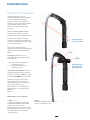
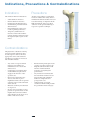
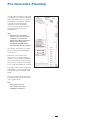
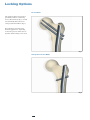
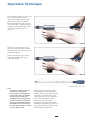
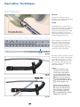
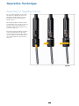
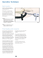
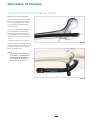
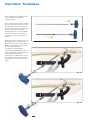
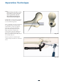
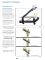
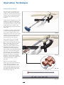
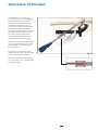
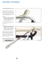
Hip T2 KnifeLight Recon Nailing System R2.0 Carpal Tunnel Ligament Release Femur Operative Technique Hip & Femur Fractures Operative Technique T2 Recon Nailing System Contributing Surgeons We greatly acknowledge and appreciate the contributions to this operative technique made by: Kevin W. Luke, M.D. Parkview Orthopaedic Group Assistant Clinical Professor Department of Orthopaedic Surgery University of Illinois Illinois, Chicago USA Anthony T. Sorkin, M.D. Rockford Orthopaedic Associates, LLP Clinical Instructor Dep. of Surgery University of Illinois College of Medicine Director Orthopaedic Traumatology Rockford Memorial Hospital Rockford, Illinois USA Ariaan D.P. van Walsum, MD Trauma surgeon Medical Spectrum Twente Enschede Netherlands Don Weber, MD, FRCSC Associate Clinical Professor of Orthopaedics Chief of Orthopaedics University of Alberta Hospital Edmonton, Alberta Canada 2 This publication sets forth detailed recommended procedures for using Stryker Osteosynthesis devices and instruments. It offers guidance that you should heed, but, as with any such technical guide, each surgeon must consider the particular needs of each patient and make appropriate adjustments when and as required. A workshop training is required prior to first surgery. All non-sterile devices must be cleaned and sterilized before use. Follow the instructions provided in our reprocessing guide (L24002000). Multi-component instruments must be disassembled for cleaning. Please refer to the corresponding assembly/ disassembly instructions. See package insert (L22000007) for a complete list of potential adverse effects, contraindications, warnings and precautions. The surgeon must discuss all relevant risks, including the finite lifetime of the device, with the patient, when necessary. Warning: Fixation Screws: Stryker Osteosynthesis bone screws are not approved or intended for screw attachment or fixation to the posterior elements (pedicles) of the cervical, thoracic or lumbar spine. 3 Contents Page 1. Introduction & Features 5 Implant Features 5 Technical Specifications 6 Instrument Features7 2. Indications, Precautions & Contraindications 8 3. Pre-operative Planning 9 4. Locking Options 10 5. Operative Technique 11 Patient Positioning and Fracture Reduction 11 Incision Entry Point Reaming Nail Selection Assembly of the Targeting Device and the Nail Nail Insertion Final Seating with Impactor Guided Locking for the Recon Mode Guided Locking for Antegrade Femoral Mode Freehand Distal Locking Set Screw or End Cap Insertion Nail Removal 11 12 14 16 17 18 18 19 29 32 34 34 Ordering Information – Implants Ordering Information – Instruments 35 37 4 Introduction Introduction Implant Features Over the past decades antegrade and retrograde femoral nailing have become widely accepted choices for the treatment of femoral fractures. The T2 Recon Nail is the realization of excellent biomechanical intramedullary stabilization for internal femoral fixation with several locking options to address fracture variability. The T2 Recon nail is one of the first femoral nailing systems to offer a greater trochanter entry point with both recon and antegrade locking options. Through the development of a common, streamlined instrument system and intuitive surgical approach, both in principle and in detail, the T2 Recon Nail offers the potential for more efficient treatment of fractures as well as simplifying the training requirements for all personnel involved. Furthermore, the T2 Recon Nail offers the following competitive advantages: • Versatility - offers the ability to switch from antegrade to a recon option without changing either the nail or targeting arm. • Recon Set Screw - this optional screw sets the most proximal Lag Screw thus minimizing the potential for screw sliding (Z-effect). • Locking Options - distal options include dynamic as well as static. As with all other T2 Nails, the T2 Recon Nail is made of Type II anodized Titanium Alloy (Ti6Al4V) for enhanced biomechanical and biomedical performance*. The T2 Recon Nail features a 125° CCD angle with a 10° anteversion angle. The 2 proximal holes, each utilize 6.5mm cannulated Lag Screws. This CCD angle allows easy insertion of the 2 lag screws into the femoral head. Alternatively a proximal 70° Oblique hole with 7° retroversion provides a 5mm Fully Threaded Screw for targeting the lesser trochanter in the Femoral Antegrade mode. The 6.5 mm Cannulated Lag Screws have a unique thread design that provide an excellent grip. Improved front cutting flutes allow for lesser insertion torque and thinner flanks for less bone removal. Secure placement of the Lag Screws within small neck diameters can be achieved due to 10mm separating the two 6.5mm lag screws or 17mm outer distance between the 6.5mm Lag screws. Two Set Screws are available: - Recon Set Screw: Tightens the 6.5mm proximal Lag Screw (Recon Mode) and - A ntegrade Set Screw: Tightens the oblique 5mm Fully Threaded Screw (Femoral Antegrade Mode). Available as left and right versions, the T2 Recon Nail incorporates an antecurvature radius of 2.0M, as well as a 4° medial lateral bend for trochanteric insertion. The distal locking configuration features a round and an oblong hole to allow for static and / or dynamic distal locking. Low profile 5mm cortical screws, common to the T2 Nailing System, are designed to simplify the surgical procedure and promote a minimally invasive approach. 5mm Fully Threaded Locking Screws are available for distal locking (Recon or Femoral Antegrade Mode) and for the proximal locking in Femoral Antegrade Mode. End Caps are available in various lengths to provide a better fit. See the detailed chart on the next page for the design specifications and size offerings. • Distal Targeting - eliminates the need for freehand locking of either the static or dynamic modes. Requires optional Gamma3/T2 Recon DTS R2.0 * A xel Baumann, Nils Zander, Ti6Al4V with Anodization Type II: Biological Behaviour and Biomechanical Effects, White Paper, March 2005. 5 Introduction Technical Specifications Recon Set Screw NailDiameter 9, 11, 13 and 15mm (Left and Right) Sizes 280−480mm, in 20mm increments Antegrade Set Screw 0mm Note: • Proximal diameter is 13mm for the 9 and 11mm Nails and 15mm for the 13 and 15mm Nails. 0mm 26mm 70° 125°Nail angle 44mm • Check with your local representative regarding availability of nail sizes. 10.5mm 4° Medial Lateral bend 17.0mm 5.0mm Fully Threaded Locking Screws L = 25–120mm Antecurvature radius 2.0M 6.5mm Cannulated Lag Screws L = 65–130mm 40mm Note: Screw length is measured from top of head to tip. 20mm 15mm 0mm end Caps Standard +5mm 6 +10mm +15mm Introduction Instrument Features A major advantage of the T2 instrument platform is the integration of core instruments that can be used not only for the complete T2 Nailing System, but for future Stryker Osteosynthesis nailing systems, thereby, reducing complexity and inventory. The T2 instrument platform offers precision and usability, as well as ergonomically styled targeting devices. B Except for the addition of a small number of dedicated instruments, the T2 Femur instrument platform is used for the T2 Recon Nail. A The T2 Recon targeting device is designed to provide two proximal locking options: Recon or Antegrade Femoral Modes. Left Reconmode: Provides two (2) proximal holes targeting the femoral neck and head: Right • B Targets the Proximal Recon 6.5 mm Lag Screw • A Targets the Distal Recon 6.5 mm Lag Screw Targeting holes for Antegrade Femoral Mode Antegrade Femoral Mode: Provides a single 5mm Oblique Screw targeting the lesser trochanter. LEFT is used for a left nail and RIGHT for a right nail. With the exception of the carbon fiber targeting device, dedicated instruments for the recon mode are color coded with “bronze”. This makes it easy to differentiate them from the core T2 instrument platform. Drills Drillsfeaturecolorcodedrings: 4.2mm = Green (Consistent with the Gamma3 and T2 Instrument Platform, this drill features a green color ring.) The 4.2mm drills are used for 5.0mm Fully Threaded Locking Screws (either for distal locking or for proximal oblique locking). Targeting holes for Recon Mode 6.5mm The Solid Stepdrill for the Lag Screw is color coded with “bronze”. 7 Precautions The T2 Recon Nail is indicated for: Stryker Osteosynthesis systems have not been evaluated for safety and use in MR environment and have not been tested for heating or migration in the MR environment, unless specified otherwise in the product labeling or respective operative technique. • • • • • • Subtrochanteric fractures Intertrochanteric fractures Ipsilateral neck/shaft fractures Comminuted proximal femoral shaft fractures Femoral fi xation required as a result of pathological disease Temporary stabilization of fractures of the femoral shaft ranging from the femoral neck to the supracondylar regions of the femur. Antegrade Mode Indications Contraindications The physician’s education, training and professional judgement must be relied upon to choose the most appropriate device and treatment. Conditions presenting an increased risk of failure include: • • • • • Any active or suspected latent infection or marked local inflammation in or about the affected area. Compromised vascularity that would inhibit adequate blood supply to the fracture or the operative site. Bone stock compromised by disease, infection or prior implantation that can not provide adequate support and/or fi xation of the devices. Material sensitivity, documented or suspected. Obesity. An overweight or obese patient can produce loads on the implant that can lead to failure of the fi xation of the device or to failure of the device itself. • • • • 8 Patients having inadequate tissue coverage over the operative site. Implant utilization that would interfere with anatomical structures or physiological performance. Any mental or neuromuscular disorder which would create an unacceptable risk of fi xation failure or complications in postoperative care. Other medical or surgical conditions which would preclude the potential benefit of surgery. Recon Mode Indications, Precautions & Contraindications Pre-Operative Planning An X-Ray Recon Template (1806-3080) is available for pre-operative planning. Thorough evaluation of pre-operative radiographs of the affected extremity is critical. Careful radiographic examination of the trochanteric region and neck regions can reduce the potential of intra-operative complications. Note: The X-Ray Recon Template features a scale of 1.15:1 which is adapted to conventional analoguous X-Rays. For digital X-Rays, attention has to be paid that the magnification is corresponding with the template. According to the fracture type either Recon or Antegrade Femoral Mode can be chosen. Evaluation of the femoral neck angle on the pre-operative X-Rays is mandatory as the T2 Recon Nail has a fixed 125° neck angle for the two Lag Screws. Proper placement of both Lag Screws in the femoral head is essential. If possible, X-Rays of the contralateral side should be used to determine the normal neck angle and length of the femur. The proper nail length should extend from the tip of the greater trochanter to the epiphyseal scar. Note: Check with your local representative regarding availability of nail sizes. 9 Locking Options Recon Mode The T2 Recon Nail can be locked proximally with two 6.5mm Lag Screws (Recon Mode, Fig. 1) or with one 5mm Fully Threaded Screw (Antegrade Femoral Mode, Fig. 2). For both Recon and Antegrade Femoral applications, depending on fracture pattern, either static or dynamic distal locking can be used. Fig. 1 Antegrade Femoral Mode Fig. 2 10 Operative Technique Patient Positioning and Fracture Reduction Patient positioning for T2 Recon Nail insertion is surgeon dependent. However, it is recommended that patients are positioned in either the supine or lateral position on a fracture table to allow closed reduction of the fracture (Fig. 3). Manipulate and reduce the fracture in the usual fashion, according to the fracture type. Reduction should be achieved as anatomically as possible. If this is not possible, reduction in one plane should be complete, leaving reduction in the other plane to be achieved prior to reaming and nail insertion. The unaffected leg is abducted as far as possible to ease image intensifier positioning. This will also allow easier access to entry point. Fig. 3 Incision The design of the T2 Recon Nail, with a 4° medial lateral bend, will only allow for insertion through the tip of the greater trochanter. With experience, the tip of the greater trochanter can be identified by palpation (Fig. 4). A longitudinal skin incision of approximately 3−5cm is made starting just above the greater trochanter to the iliac crest (Fig. 5). The incision is then deepened to expose the tip of greater trochanter. Fig. 4 Smaller or larger incisions may be used based on individual patients anatomy and at the surgeon’s discretion. Note: The targeting instruments of the T2ReconNailhavebeendesigned to allow for a more percutaneous approach. Fig. 5 11 Operative Technique Entry Point • The Tip of the greater Trochanter The entry point is located at the junction of the anterior third and posterior two-thirds of the greater trochanter on the medial edge of the tip itself (Fig. 6). Note: Before opening the tip of greater trochanter, image intensifier views(A/PandM/L)should be used to confirm correct identification of the entry point. 1 anterior /3 2 Fig. 6 /3 posterior The medullary canal can be opened with the • CurvedAwl/CurvedAwl,90° Handle or • OneStepConicalReamer. Note: Densecorticalbonemayblock the tip of the Awl during opening of the entry portal. Inserting first the optional Awl Plug into the Awl will avoid penetration of bone debris into the cannulated Awl shaft. The Awl Plug is thenremovedforGuideWire insertion. Fig. 7a • Entry point with Curved Awl Once the tip of the greater trochanter has been opened (Fig. 7a), the Ø3 × 1000mm Ball Tip Guide Wire may be advanced through the cannulation of the Curved Awl with the Guide Wire Handle and Chuck (Fig. 7b). The proximal femur may then be prepared with the One Step Conical Reamer. Fig. 7b 12 Operative Technique • Entry point with One Step Conical Reamer Alternatively, the 13mm diameter One Step Conical Reamer for the 9 and 11mm nails or the 15mm diameter Reamer for the 13 and 15mm nails may be used for opening the medullary canal and reaming of the trochanteric region. K-Wire Under image intensification control, the entry point is made with a Ø3.2 × 400mm Recon K-Wire which is attached to the Guide Wire Handle and advanced into the medullary canal. Confirm its placement within the center of the medullary canal on A/P and lateral image intensifier views. Fig. 8a Note: TheReconK-Wireusedforthe entry point should not be used again for the Lag Screw insertion. It is recommended that a new K-Wirebeutilized. Fig. 8 The Recon Protection Sleeve and Multi-hole Trocar are positioned with the central hole over the K-Wire. Note: The Multi-hole Trocar has a special design for more precise insertionoftheØ3.2mmRecon K-Wire(Fig.8).Besidethecentral hole, 4 other holes are located eccentrically at different distances from the center (Fig. 8a) to easily revise insertion of the guiding K-Wireintheproperposition (entry point). When correct placement of the guiding Recon K-Wire is confirmed on image intensifier views (A/P and lateral), keep the Tissue Protection Sleeve in place and remove the Multi-hole Trocar. The T-Handle is attached to the One Step Conical Reamer and hand reaming is performed over the Recon K-Wire through the Tissue Protection Sleeve (Fig. 9). The Recon K-Wire is then removed and replaced with the Ø3 × 1000mm Ball Tip Guide Wire. Fig. 9 13 Operative Technique Reaming The Ø 3 × 1000mm Ball Tip Guide Wire is inserted with the Guide Wire Handle through the fracture site to the level of the epiphyseal scar. The Ø 9mm Universal Rod with Reduction Spoon may be used as a fracture reduction tool to facilitate Guide Wire insertion through the fracture site (Fig. 10). Note: The Ball Tip at the end of the GuideWirewillstoptheBixcut reamer* head (Fig. 11). Fig. 10 Caution: Prior to reaming, it is important to check the centered intramedullary position of the GuideWirewiththeimageintensifier. Lateral displacement oftheGuideWirecouldleadto resection of more bone on the lateral side of the wire, which in turn will lead to an offset position of the nail and increase the risk of a shaft fracture. Fig. 11 Note: Make sure that the reduction is maintained throughout the reaming process. Reaming is commenced in 0.5mm increments until cortical contact occurs (Fig. 12). For easier nail insertion, the medullary canal should be reamed at least 2mm more than the diameter of selected nail (Fig. 13). Fig. 12 + 2mm more than the selected nail diameter Fig. 13 * see pages 36-37 for additional Bixcut Reamer system details 14 Operative Technique The Guide Wire Pusher can be used to keep the Guide Wire in position during reamer shaft extraction. The metal cavity at the end of the blue Elastosil handle may be placed on the end of Guide Wire. Applying pressure to hold the Guide Wire in place while removing the drill under power. (Fig. 14). Fig. 14 When close to the Guide Wire end, place the Guide Wire Pusher with its funnel tip at the end of the power tool cannulation (Fig. 15). While removing the power tool the Guide Wire Pusher will keep the Guide Wire in place. Fig. 15 Guide Wire Pusher (1806-0271) Note: TheT2ReconNailmaybeinserted without reaming of the subtrochanteric and diaphyseal region of the femur, particularly in eldery patients with wide medullary canals. If appropriate, after the trochanteric region has been prepared with the One Step ConicalReamer,thenailcanbe inserted without further reaming of the medullary canal. Reaming of the trochanteric region is needed (Fig. 13) as the proximal nail diameter (driving end) is larger than the nail diameter (13mm for the 9 and 11mm diameter nails and 15mm for the 13 and 15mm diameter nails). For both reamed or unreamed applications, the proximal 5cm of the trochanteric region must be opened to at least 13mm or 15mm, depending on the proximal diameter of the nail. 15 Operative Technique Nail Selection Diameter The diameter of the selected nail should be at least 2.0mm smaller than that of the last reamer used. Length end of guide Wire Ruler is measurement reference Fig. 16a Nail length may be determined by measuring the remaining length of the Guide Wire. The Guide Wire Ruler may be used by placing it on the Guide Wire and reading the correct nail length at the end of the Guide Wire on the Guide Wire Ruler (Fig. 16a, b). Upon completion of reaming, the appropriate size nail is ready for insertion. A unique design feature of the T2 Recon Nail is that the Ø3 × 1000mm Ball Tip Guide Wire does not need to be exchanged. Fig. 16b The selected nail is assembled onto the Targeting Arm with the Nail Holding Screw (Fig. 17a). Be sure to securely tighten the Nail Holding Screw with the Screwdriver Shaft, Ball Tip and T-Handle so that it does not loosen during nail insertion. Fig. 17a Caution: Prior to the nail insertion, check the correct assembly by passing the Stepdrill for LagScrewthroughtheRecon Tissue Protection Sleeve and DrillSleeve,Recon(placedin the corresponding hole of the Targeting Arm) and through the holes of the nail (Fig. 17b). For the Antegrade Femoral Mode, use the targeting hole for Antegrade with the Tissue ProtectionSleeveandDrill Sleeve assembly to pass the Ø4.2×340mmDrillthroughthe oblique hole of the nail. Fig. 17b 16 Operative Technique Assembly of Targeting Device First, assemble the Knob to the Targeting Device by aligning the arrow on the Knob with the white line on the Target Sleeve, (Fig. 18a) then push hard to click it. By turning the Knob clockwise to the position labeled (A), the sleeve inserted in target (A) position, which is the distal Recon Mode targeting hole, can be locked. (Fig. 18b) By further turning the Knob clockwise to the position labeled (A+B), both sleeves inserted in (A) and (B), which are the both proximal and distal recon mode targeting holes, can be locked. (Fig. 18c) Fig. 18a Fig. 18b 17 Fig. 18c Operative Technique Nail Insertion The nail is advanced through the entry point passing the fracture site to the appropriate level. If dense bone is encountered, first re-evaluate that sufficient reaming has been achieved, then, if necessary, the Strike Plate can be attached to the Targeting Arm and the Slotted Hammer may be used to further insert the nail (Fig. 19). Caution: The nail must progress smoothly, without excessive force. If too much resistance is encountered, removal of the nail and additional reaming is recommended. Fig. 19 Note: RemovetheGuideWirepriorto drillingorK-Wireinsertion. Final Seating with Impactor The carbon fiber guide should never be struck as it may break or become deformed. The impactor that is provided can be utilized to assist with final seating of the nail. Gentle tapping will produce small adjustments (in the nail position) that can help to optimize the ultimate position of the lag screw in the femoral head. The nail holding screw should be re-tightened following any use of the impactor. The impactor should not be utilized to force the nail down the canal. If the nail cannot be seated manually or if there is no advancement each time the impactor is tapped, A/P and Lateral fluoroscopic X-Rays should be reviewed to determine the cause of the impingement - there may be a mismatch between the nail geometry and the medullary canal. The starting position, the femoral bow and the canal diameter should all be examined to ensure that the leading end of the nail is not impinging on the medial or anterior cortex and that the canal itself has been sufficiently reamed. Periodically, nail removal and further reaming of the diaphysis may be required. The proximal metaphyseal flair may be undersized (particularly in young patients or those of short stature) and serve to prevent nail advancement. If this situation is encountered, a flexible reamer may be used to further widen this area to the level of the lesser trochanter. To facilitate manual passage, the nail internally rotated 90° until the fracture has been passed. 18 Operative Technique Guided Locking for the Recon Mode Nail / Lag Screws Positioning Drive the T2 Recon Nail to the depth that correctly aligns the proximal screw holes parallel with the femoral head and neck under fluoroscopic control (Fig. 20). Two aspects regarding the Nail/Lag Screws position must be carefully checked with the image intensifier before drilling into the femoral head: - Alignment of the anteversion (M//L view) - Depth of nail insertion (A/P view). Fig. 20 The distal Lag Screw should run along the calcar region (on the A/P view) and centered into the femoral neck and head (on the M/L view). Note: TheuseoftheOneShotDevice (1213-3010) is recommended to predetermine the optimal Lag Screwplacement.Detailsare described on Page 20 to 21. Fig. 20a 19 Operative Technique Now attach the Recon Paddle Trocar to the T-Handle, AO Medium Coupling (Fig. 21). Then, advance them together with the Recon Tissue Protection Sleeve to the skin through the hole on the Target Device labeled (A). Make a small skin incision and push the assembly through until it is in contact with the lateral cortex. Then turn the Knob clockwise to the position labeled (A) (Fig. 22). Remove the Trocar and then insert the Recon K-Wire Sleeve through the Tissue Protection Sleeve. Place a Recon K-Wire into the K-Wire Inserter and attach it to the T-Handle. The K-Wire is then manually advanced through the K-Wire Sleeve until it reaches the subchondral bone of the femoral head (Fig. 23). Alternatively, the K-Wire Inserter can be attached to a Power Tool and the Recon K-Wire is inserted to the same depth. Fig. 21 Fig. 22 Fig. 23 20 Operative Technique Note: With the image intensifier, verify iftheK-Wireisplacedalongthe calcarregionintheA/Pview and central on the lateral view (correct anteversion) (Fig. 24). If the K-Wire is incorrectly positioned, the first step is to remove it and then to correct the nail position. More commonly, the nail is positioned too proximal and correction of the nail should be carried out either by hand or by using the Strike Plate placed into the Target Device. If a higher position is required, the Universal Rod and Slotted Hammer may then be attached to the Strike Plate to carefully and smoothly extract the assembly (Fig. 25). Fig. 24 The new position is checked again with the image intensifier as described above. Fig. 25 21 Operative Technique Nail/Lag Screws Positioning with the One Shot Device The use of the One Shot device (1213-3010) is recommended to predetermine the optimal Lag Screw placement* (Fig. 26). The One Shot Device is made of carbon fiber and works by providing a target to indicate the position of the K-Wire on the fluoroscope screen. The target contains 3 radio-opaque wires embedded in the arm – a dashed inner wire and two solid outer wires. These wires work like a gun sight to indicate the position of the K-Wire. The One Shot Device is attached by slightly pressing the grip and releasing it when positioned onto the Tissue Protection Sleeve. To correct the position or remove the device, the grip must be pressed. Note: TheuseoftheOneShotDevice should not replace any steps in the T2ReconOperativeTechnique. Fig. 26 While pressing the attachment grip, the device is positioned between the anterior aspect of the patient’s hip and the fluoroscope screen positioned for an A/P view of the hip (Fig. 26, 27). Note: It is important to drape the patient so that the OneShotDevicedoes not interfere with any drapes anterior to the patient’s hip. too cranial nail position When positioned correctly, the target will appear in the fluoroscopic image (A/P view) with the dashed inner wire in the middle of the two solid outer wires (Fig. 27). If it does not, the One Shot Device should be moved towards or away from the patient by pressing the grip slightly until the target is seen as described above. optimal nail position * Tokunaga et al, Correct lag screw positioning for the Gamma Nail: Development for the targeting device for insertion, Osteo Trauma Care 2005; 13:14-17 too caudal nail position A/Pview 22 Fig. 27 Operative Technique To identify the accurate position, the dashed wire of the target must appear between the two solid wires at the desired position. If the position is incorrect the T2 Recon Nail position may be corrected by either pulling backwards or pushing forwards (Fig. 28). The K-Wire can then be placed into the femur and the targeting arm is held in place until the K-Wire’s position in the lateral view has been determined. When positioned correctly, the target will appear in the fluoroscopic lateral view (Fig. 29). If the dashed wire of the target appears between the two solid wires, then advance the Recon Tissue Protection Sleeve and Trocar as shown in Fig. 21. Fig. 28 Warning: PriortoadvancingtheK-Wire, check the correct guidance throughtheK-WireSleeve.Do notusebentK-Wires. Note: TheK-Wireinsertedintothemost distal Lag Screw hole of the nail helps in achieving the correct positioning of the nail (depth and rotation) with minimal resection of bone in case correction of the position is needed. Lateral view 23 Fig. 29 Operative Technique Solid Stepdrill Technique For the insertion of proximal screws in Recon Mode, the Solid Stepdrill Technique, which is mentioned in this chapter, is the recommended method to optimize the proximal targeting accuracy. Attach the Recon Paddle Trocar to the T-Handle, AO Medium Coupling as demonstrated in Fig. 21. Then slide the Tissue Protection Sleeve together with the Paddle Trocar assembly to the skin through the proximal target hole labeled (B). A small skin incision is made and the assembly is pushed through until it is in contact with the lateral cortex. When the tip of the sleeve is in contact with the lateral cortex, lock the sleeve by turning the knob further to the position labeled (A+B) (Fig. 30). Fig. 30 Then remove the Trocar assembly and insert the Drill Sleeve for the Recon Solid Stepdrill while the distal K-Wire and K-Wire Sleeve are still left in place. The Drill Sleeve for the Recon Solid Stepdrill is inserted through the proximal target hole labeled (B) of the Targeting Device. The Ø6.5mm Solid Stepdrill for Recon Lag Screw is forwarded through the Tissue Protection Sleeve and Drill Sleeve assembly and pushed onto the lateral cortex. There is a dedicated Drill Sleeve for the Solid Stepdrill Technique. This Sleeve is marked “Use with Solid Step Drill“ as shown (Fig. 31b). Fig. 31 Reaming is performed under fluoroscopic control just until the tip of the Solid Stepdrill for Lag Screw reaches the subchondral bone. The required length of the Lag Screw can be read directly off the Recon Solid Stepdrill for Lag Screw at the end of the Drill Sleeve (Fig. 31a). Fig. 31a Fig. 31b 24 Operative Technique Using the Recon Screwdriver the correct Lag Screw is inserted through the Tissue Protection Sleeve and threaded up to the subcondral part of the femoral head. The screw is near its proper seating position when the groove around the shaft of the screwdriver is approaching the end of the Tissue Protection Sleeve (Fig. 32, 32a). The required length of the second Lag Screw can be measured using the Recon Lag Screw Gauge. Remove the Distal K-Wire and K-Wire Sleeve. Then insert the Sleeve for the solid Stepdrill into the distal Tissue Protection Sleeve. Repeat the same surgical steps for drilling and insertion of the distal Lag Screw without K-Wire guidance. Fig. 32 After the completion of the distal Lag Screw insertion, move on to the distal locking procedure. Fig. 32a 25 Operative Technique Alternatively, the K-Wire can be used prior to drilling with the Solid Drill. Place a second Recon K-Wire into the K-Wire Inserter and attach it to the T-Handle or power tool. The K-Wire is then advanced through the K-Wire Sleeve until it reaches the subchondral bone of the femoral head. Warning: CorrectplacementoftheK-Wire tip in subchondral bone must be checked with image intensifier in bothA/PandM/Lviews. The required length of the Lag Screw is measured using the Recon Lag Screw Gauge. Fig. 32b Note: Before starting to measure, ensure that the Tissue Protection Sleeve andK-WireSleeveassemblyis firmly pressed against the lateral cortex of the femur (Fig. 32b). Take the Recon Lag Screw Gauge and place it directly under the K-Wire and against the K-Wire Sleeve (Fig. 32c). The correct Lag Screw length corresponds to the measurement indicated at the end of the K-Wire on the Lag Screw Gauge. After the measurement, remove the K-Wire and drill the channel with the Solid Stepdrill according to the Solid Stepdrill technique described on page 22. Fig. 32c 26 Operative Technique Cannulated Stepdrill Technique As the Cannulated Stepdrill technique was also discussed in a previous version of the operative technique, the insertion of the proximal screws in Recon Mode using this method will also be mentioned as a potential option. After achieving a satisfactory position of the first Recon K-Wire slide the second Recon Tissue Protection Sleeve together with the Recon K-Wire Sleeve into the proximal target hole on the Targeting Arm, labeled (B). A small skin incision is made and the assembly is pushed through until it is in contact with the lateral cortex (Fig. 33). Fig. 33 Place a second Recon K-Wire into the K-Wire Inserter and attach it to the T-Handle or power tool. The K-Wire is then advanced through the K-Wire Sleeve until it penetrates the subchondral bone of the femoral head. Caution: CorrectplacementoftheK-Wire tip in subchondral bone must be checked with image intensifier in bothA/PandM/Lviews. The required length of the Lag Screw is measured using the Recon Lag Screw Gauge (1806-3035). Before starting to measure, ensure that the Tissue Protection Sleeve and K-Wire Sleeve assembly is firmly pressed against the lateral cortex of the femur. Take the Recon Lag Screw Gauge and place it directly under the distal K-Wire and against the K-Wire Sleeve (Fig. 34). Fig. 34 The correct Lag Screw length corresponds to the measurement indicated at the end of the K-Wire on the Lag Screw Gauge. This length will then be set on the cannulated Recon Stepdrill for Lag Screw (Fig. 35). Fig. 35 27 Operative Technique Caution: Before proceeding with drilling for the selected Lag Screw, check theA/Pfluoroscopicviewsto seeifthetwoReconK-Wiresare parallel. The distal K-Wire Sleeve is removed while the Tissue Protection Sleeve remains in position (Fig. 36a). The cannulated Ø6.5mm Recon Stepdrill for Lag Screw (REF 1806-3025) is forwarded through the Tissue Protection Sleeve and pushed onto the lateral cortex. The stop on the drill will only allow drilling up to 5mm before the K-Wire ends (Fig. 36b). Fig. 36a Warning: Donotusethecannulated ReconStepdrillforLagScrew overadeflectedK-Wire. Fig. 36b Using the Recon Screwdriver, the selected Lag Screw is inserted through the Tissue Protection Sleeve and threaded up to the subchondral bone of the femoral head. The screw is near its proper seating position when the groove around the shaft of the screwdriver is approaching the end of the Tissue Protection Sleeve (Fig. 37). Alternatively, the Recon Screwdriver Shaft may be assembled into the T-Handle and used for the Lag Screw insertion. Fig. 37 The required length of the second Lag Screw is measured using the Recon Lag Screw Gauge. Repeat the same surgical steps for drilling and insertion of the proximal Lag Screw (Fig. 38). After the completion of the distal Lag Screw insertion, move on to the proximal locking procedure. Fig. 38 28 Operative Technique Guided Locking for Antegrade Femoral Mode Now attach the Paddle Trocar, Antegrade and the AO T-Handle Medium Coupling (Fig. 39). Then, advance them together with the Long Tissue Protection Sleeve through the targeting hole for the Antegrade Femoral Mode (left or right) by pressing the safety clip (Fig. 40). The mechanism will keep the sleeve in place and prevent it from falling out. It will also prevent the sleeve from sliding during screw measurement. To release the Tissue Protection Sleeve, the safety clip must be pressed again. Fig. 39 A small skin incision is made and the assembly is pushed through by manipulating the T-Handle until the Tissue Protection Sleeve is in contact with the lateral cortex (Fig. 41). Fig. 40 Fig. 41 29 Operative Technique Pre-drilling the lateral cortex Pre-drilling opens the lateral cortex for the drill entry. Pre-drilling helps to prevent a possible slipping of the drill on the cortex and may avoid deflection within the cancellous bone. The Paddle Trocar Assembly is then removed and the Drill Sleeve is inserted through the Long Tissue Protection Sleeve (Fig. 42). With the Long Tissue Protection Sleeve firmly engaged in the cortex, the lateral cortex should be opened using the centered tip green coded 4.2mm Drill. Fig. 42 The Drill can be connected with the AO Teardrop Handle Coupling allowing pre-drilling by hand (Fig. 43). It also can be done using power. Note: For optimal stability, the tip of the oblique screw should be positioned at the level of the lesser trochanter (Fig. 44). Then use the center-tipped, calibrated Ø4.2 × 340mm Drill and drill through both cortices (Fig. 45). Fig. 43 The screw length may be read directly from the Calibrated Drill at the end of the Drill Sleeve (Fig. 45a). Caution: Start the drill before touching the bone and then keep a gentle pressure on the pre-drilled cortex to ensure accurate drilling. Fig. 44 Note: The position of the drill end, as it relates to the far cortex, is the same position where the screw will end. 65mm Fig. 45a Fig. 45 30 Operative Technique Therefore, if the end of the Drill is 3mm beyond the far cortex, the end of the screw will also be 3mm beyond (Fig. 46). Check the position oftheendoftheDrillwithimage intensification before measuring the screw length. If the screw measurement using the Long Screw Gauge is preferred, first remove the Long Drill Sleeve and read the screw length directly at the end of the Long Tissue Protection Sleeve. 6 5m m Note: • Before starting to measure, ensure that the Tissue Protection Sleeve/DrillSleeveAssemblyand K-WireSleeveassemblyisfirmly pressed against the lateral cortex of the femur (Fig. 46, 47). • TheLongScrewGaugeis calibrated so that with the bend at the end pulled back flush with the far cortex, the screw tip will end 3mm beyond the far cortex (Fig. 47). Fig. 46 When the Drill Sleeve is removed, the correct Locking Screw is inserted through the Tissue Protection Sleeve using the Long Screwdriver Shaft with Teardrop Handle (Fig. 48). The screw is advanced through both cortices. The screw is near its proper seating position when the groove around the shaft of the screwdriver is approaching the end of the Tissue Protection Sleeve (Fig. 48a). Fig. 47 Fig. 48 Fig. 48a 31 Operative Technique Freehand Distal Locking The freehand technique is used to insert Fully Threaded Locking Screws into both distal transverse holes in the nail. Rotational alignment must be checked prior to locking the nail. This is performed by checking a lateral view at the hip and a lateral view at the knee. The anteversion should be the same as on the contralateral side. Multiple locking techniques and radiolucent drill devices are available for freehand locking. The critical step with any freehand locking technique, proximal or distal, is to visualize a perfectly round locking hole with the C-Arm. Fig. 49 The center-tipped ø4.2 × 180mm Drill is held at an oblique angle to the center of the locking hole (Fig. 49). Upon X-Ray verification, the Drill is placed perpendicular to the nail and drilled through the lateral and medial cortices (Fig. 50). Confirm in both the A/P and lateral views by X-Ray that the Drill passes through the hole in the nail. Fig. 50 After drilling both cortices, the screw length may be read directly off of the Long Screw Scale at the green ring on the center-tipped ø4.2 × 180mm Drill (Fig. 51). green Ring Alternatively, the Screw Gauge for freehand technique can be used insted of the Long Screw Scale to determine the screw length. Fig. 51 Routine Locking Screw insertion is employed with the assembled Long Screwdriver Shaft and Teardrop Handle. Note: The Screwdriver Shaft can be used in conjunction with the Long Screw Capture Sleeve. 32 Operative Technique Repeat the locking procedure for the insertion of the second 5mm Fully Threaded Locking Screw into the oblong hole in a static position (Fig. 52). The T2ReconNail may be used in the dynamic locking mode. When the fracture pattern permits, dynamic lock ing may be utilized for transverse, rotationally stable fractures. While dynamic locking can only be performed at the end of the nail, this will require a freehand distal targeting of the oblong hole in a dynamic position. This al lows the nail to move and the fracture to settle while torsional stability is maintained. Fig. 52 Note: As an alternative for distal locking, the guided distal targeting system can be used. For details, please refer to the separate operativetechniques(Distal TargetingSystemGamma3Long NailR2.0,T2ReconnailR2.0)or askStrykerRepresentativefor further assistance. Release the Nail Holding Screw using the Screwdriver Shaft, Ball Tip and T-Handle. Then remove the Targeting Arm to complete surgery. 33 Operative Technique Set Screw or End Cap Insertion After removal of the Target Device, a Set Screw or End Cap can be used. Set Screw, Recon Two different Set Srews are available (Fig. 53a): - a ReconSetScrewto tighten down on the Proximal Lag Screw for the Recon Mode - an Antegrade Set Screw to tighten down on the oblique Fully Threaded Screw for the Femoral Antegrade Mode Set Screw, Antegrade End Caps Standard Fig. 53a +5mm +10mm +15mm Fig. 53b Note: If a Set Screw is used, an End Cap can no longer be inserted. Four different sizes of End Caps are available to adjust nail length and to reduce the potential for bony ingrowth into the proximal thread of the nail (Fig. 53b). Fig. 54 The Set Screw or End Cap is inserted with the Long Screwdriver Shaft and Teardrop Handle after intra-operative radiographs confirm satisfactory reduction and hardware implantation (Fig. 54). Be sure to fully seat the End Cap or Set Screw to minimize the potential risk for loosening. Nail Removal Fig. 55 The Set Screw or End Cap is removed with the Long Screwdriver Shaft and Teardrop Handle (Fig. 55). The Universal Rod is inserted into the driving end of the nail. Alternatively, the Conical Extraction Rod, can be attached to the Universal Rod to facilitate extraction of the nail. All 5mm Fully Threaded Locking Screws are removed with the Screwdriver, Selfholding. The optional Long Screw Capture Sleeve may be used on the Screwdriver Shaft. For removal of the Lag Screws, the Recon Screwdriver or the Recon Screwdriver Shaft and T-Handle are to be used. Fig. 56 The Slotted Hammer is used to extract the nail in a controlled manner (Fig. 56). 34 Ordering Information – Implants T2 Recon Nail, Left T2 Recon Nail, Right Titanium REF Diameter mm Length mm Titanium REF Diameter mm Length mm 1846-0928S 1846-0930S 1846-0932S 1846-0934S 1846-0936S 1846-0938S 1846-0940S 1846-0942S 1846-0944S 1846-0946S 1846-0948S 9.0 9.0 9.0 9.0 9.0 9.0 9.0 9.0 9.0 9.0 9.0 280 300 320 340 360 380 400 420 440 460 480 1847-0928S 1847-0930S 1847-0932S 1847-0934S 1847-0936S 1847-0938S 1847-0940S 1847-0942S 1847-0944S 1847-0946S 1847-0948S 9.0 9.0 9.0 9.0 9.0 9.0 9.0 9.0 9.0 9.0 9.0 280 300 320 340 360 380 400 420 440 460 480 1846-1128S 1846-1130S 1846-1132S 1846-1134S 1846-1136S 1846-1138S 1846-1140S 1846-1142S 1846-1144S 1846-1146S 1846-1148S 11.0 11.0 11.0 11.0 11.0 11.0 11.0 11.0 11.0 11.0 11.0 280 300 320 340 360 380 400 420 440 460 480 1847-1128S 1847-1130S 1847-1132S 1847-1134S 1847-1136S 1847-1138S 1847-1140S 1847-1142S 1847-1144S 1847-1146S 1847-1148S 11.0 11.0 11.0 11.0 11.0 11.0 11.0 11.0 11.0 11.0 11.0 280 300 320 340 360 380 400 420 440 460 480 1846-1328S 1846-1330S 1846-1332S 1846-1334S 1846-1336S 1846-1338S 1846-1340S 1846-1342S 1846-1344S 1846-1346S 1846-1348S 13.0 13.0 13.0 13.0 13.0 13.0 13.0 13.0 13.0 13.0 13.0 280 300 320 340 360 380 400 420 440 460 480 1847-1328S 1847-1330S 1847-1332S 1847-1334S 1847-1336S 1847-1338S 1847-1340S 1847-1342S 1847-1344S 1847-1346S 1847-1348S 13.0 13.0 13.0 13.0 13.0 13.0 13.0 13.0 13.0 13.0 13.0 280 300 320 340 360 380 400 420 440 460 480 1846-1528S 1846-1530S 1846-1532S 1846-1534S 1846-1536S 1846-1538S 1846-1540S 1846-1542S 1846-1544S 1846-1546S 1846-1548S 15.0 15.0 15.0 15.0 15.0 15.0 15.0 15.0 15.0 15.0 15.0 280 300 320 340 360 380 400 420 440 460 480 1847-1528S 1847-1530S 1847-1532S 1847-1534S 1847-1536S 1847-1538S 1847-1540S 1847-1542S 1847-1544S 1847-1546S 1847-1548S 15.0 15.0 15.0 15.0 15.0 15.0 15.0 15.0 15.0 15.0 15.0 280 300 320 340 360 380 400 420 440 460 480 Note: Check with your local representative regarding availability of nail sizes. 35 Ordering Information – Implants 6.5mm Lag Screws 5mm Fully Threaded Locking Screws Titanium REF Diameter mm Length mm Titanium REF 1897-6065S 1897-6070S 1897-6075S 1897-6080S 1897-6085S 1897-6090S 1897-6095S 1897-6100S 1897-6105S 1897-6110S 1897-6115S 1897-6120S 1897-6125S 1897-6130S 6.5 6.5 6.5 6.5 6.5 6.5 6.5 6.5 6.5 6.5 6.5 6.5 6.5 6.5 65 70 75 80 85 90 95 100 105 110 115 120 125 130 1896-5025S 1896-5030S 1896-5035S 1896-5040S 1896-5045S 1896-5050S 1896-5055S 1896-5060S 1896-5065S 1896-5070S 1896-5075S 1896-5080S 1896-5085S 1896-5090S 1896-5095S 1896-5100S 1896-5105S 1896-5110S 1896-5115S 1896-5120S 5.0 5.0 5.0 5.0 5.0 5.0 5.0 5.0 5.0 5.0 5.0 5.0 5.0 5.0 5.0 5.0 5.0 5.0 5.0 5.0 Titanium REF Diameter mm Length mm Titanium REF Diameter mm Length mm 1822-0003S 1847-0005S 1847-0010S 1847-0015S 8.0 13.0 13.0 13.0 Standard + 5mm +10mm +15mm 1847-0001S 1847-0003S 8.0 8.0 Set Screw, Recon Set Screw, Antegrade end Caps DiameterLength mm mm 25.0 30.0 35.0 40.0 45.0 50.0 55.0 60.0 65.0 70.0 75.0 80.0 85.0 90.0 95.0 100.0 105.0 110.0 115.0 120.0 Set Screws Note: Check with your local representative regarding availability of nail sizes. Implants are in sterile packaging. Outside of the U. S., Locking Screws may be ordered non-sterile without the “S” at the end of the corresponding catalog number. 36 Ordering Information – Instruments REF Description T2 Basic Long 702429 Teardrop Handle, AO Coupling** 703165 Protection Sleeve, Retrograde*** 1806-0022 Guide Wire Ruler 1806-0032 Awl Plug 1806-0041 Awl 1806-0110 Universal Rod 1806-0125 Reduction Spoon 1806-0130 Wrench 8mm/10mm 1806-0135 Insertion Wrench, 10mm*** 1806-0150 Strike Plate 1806-0170 Slotted Hammer 1806-0185 Tissue Protection Sleeve, Long 1806-0203 Screwdriver, Self-Holding, Extra Short (3.5) 1806-0215 Drill Sleeve, Long 1806-0227 Screwdriver Shaft AO, Long 1806-0233 Screwdriver, Self-Holding, Long (3.5) 1806-0268 Screwdriver Shaft, Compression (hex3.5)*** 1806-0271 Guide Wire Pusher 1806-0315 Trocar, Long*** 1806-0325 Screw Gauge, Long 1806-0331 Screw Gauge (20-120mm) 1806-0350 Extraction Rod, Conical (Ø8mm) 1806-0365 Screw Scale, Long 1806-1095 Guide Wire Handle 1806-1096 Guide Wire Handle Chuck 1806-2014 Rigid Reamer Ø12mm*** 1806-9900 T2 Basic Long Instrument Tray 1806-9901 T2 Basic Long Instrument Set, Completely filled **Caution: The coupling of Elastosil handles contains a mechanism with one or multiple ball bearings. In case of applied axial stress on the Elastosil handle, those components are pressed into the surrounding cylinder resulting in a complete blockage of the device and possible bending. To help avoid intra-operative complications and promote long-term functionality, we mandate that Elastosil handles be usedonlyfortheirintendeduse.DONOT HITthem. *** items are part of T2 Basic Long Instrument set (1806-9901); however, not used for T2ReconNailingsurgery 37 Ordering Information – Instruments REF Description T2ReconInstruments 1806-3100 Target Device 1806-3101 Knob for Target Device 1806-3005 Nail Holding Screw, Recon 1806-3010 One Step Conical Reamer Ø13, Recon 1806-3015 One Step Conical Reamer Ø15, Recon 1806-3026S Solid Stepdrill for Lag Screw* 1806-3030S Recon K-Wire, Recon* 1806-3031S K-Wire, Recon, CoCr 1806-3035 Lag Screw Gauge, Recon 1806-3040 K-Wire Sleeve, Recon 1806-3041 Drill Sleeve for Solid Stepdrill 1806-3045 Tissue Protection Sleeve, Recon 1806-3050 Screwdriver Shaft, Recon 1806-3055 Multihole Trocar 1806-3057 Protection Sleeve, Antegrade 1806-3060 Screwdriver, Recon 1806-3070 K-Wire Inserter 1806-3090 Screwdriver Shaft, AO, Ball Tip 1806-0294 Screwdriver Shaft, Selfholding, 3.5 × 85mm 1806-4290S Drill Ø4.2 × 230mm, AO* 1806-4260S Drill Ø4.2 × 340mm, AO* 1806-4270S Drill Ø4.2 × 180mm, AO* 1806-8018S Drill Ø4.2 × 250mm, oblique AO* * For non-sterile, leave “S” off the REF number when ordering. 38 Ordering Information – Instruments REF Description T2ReconInstruments 1213-3010 One Shot Device 702628 T-Handle, AO Medium Coupling** 1806-3065 Extraction Screwdriver 1806-0085S Guide Wire, Ball Tip, Ø3 × 1000mm, sterile* 1806-3047 T2 Paddle Trocar Recon Mode 1806-3048 T2 Paddle Trocar Antegrade Mode 1806-3080 X-Ray Template, Recon 1806-9990 T2 Recon Instrument Tray 1806-9991 T2 Recon Instrument Set, completely filled REF Description Optional Instruments 1806-0040 Awl, Curved 1806-3025 Stepdrill for Lag Screw, Recon 1806-0240 Screw Capture Sleeve, Long 1806-0292 Screwdriver Shaft, 3.5 x 85mm 1806-0480 Screw Gauge, Femur REF Description Spare Parts * For non-sterile, leave “S” off the REF number when ordering. **Caution: The coupling of Elastosil handles contains a mechanism with one or multiple ball bearings. In case of applied axial stress on the Elastosil handle, those components are pressed into the surrounding cylinder resulting in a complete blockage of the device and possible bending. 1806-9993 T2 Recon Instrument Tray Insert 1806-9992 T2 Recon Silicone Mat Free Space 1806-9995 T2 Recon Drill Rack 1806-9996 T2 Recon Insert for Reamer Heads**** 1320-5375 DTS Tray Calibration Stand To help avoid intra-operative complications and promote long-term functionality, we mandate that Elastosil handles be usedonlyfortheirintendeduse.DONOT HITthem. **** Bixcut Modular Head 9, 10, 11, 12, 13, 14, 15, 16, 17 and 2 additional Modular Heads can be stored. See page 37 for details. 39 Ordering Information – Instruments Bixcut Complete range of modular and fixed-head reamers to match surgeon preference and optimize O.R.efficiency,presentedinfully sterilizable cases. Large clearance rate resulting from reduced number of reamer blades coupled with reduced length of reamer head to allow for effective relief of pressure and efficient removal of material 3. Cutting flute geometry optimized to lower pressure generation3. Forward- and side-cutting face combination produces efficient material removal and rapid clearance3. Double-wound shaft transmits torque effectively and with high reliability. Low-friction surface fi nish aids rapid debris clearance3. Typical Standard Bixcut ReamerØ14mm ReamerØ14mm Clearance area : 32% of cross section Clearance area : 59% of cross section Smaller, 6 and 8mm shaft diameters are designed to reduce IM pressure. Studies1 have demonstrated that the pressures developed within the medullary cavity through the introduction of unreamed IMnails can be far greater than those developed during reaming − but this depends very much upon the design of the reamer. After a three year development study2 involving several universities, the factors that determine the pressures and temperatures developed during reaming were clearly established. These factors were applied to the development of advanced reamers that demonstrate significantly better performance than the best of previous designs 3 . 1 Jan Paul M. Frolke, et al. ; Intramedullary Pressure in Reamed Femoral Nailing with Two Different Reamer Designs., Eur. J. of Trauma, 2001 #5 2 Medhi Moussavi, et al.; Pressure Changes During Reaming with Different Parameters and Reamer Designs, Clinical Orthopaedics and Related Research Number 373, pp. 295-303, 2000 Bixcut 3 Andreas Speitling; Intramedullary Reamers, commented slides of internal test report, Sep 1999 40 Ordering Information – Instruments Bixcut Fixed Head − AO Fitting** Bixcut Modular Head REF Description 0226-3090 0226-3095 0226-3100 0226-3105 0226-3110 0226-3115 0226-3120 0226-3125 0226-3130 0226-3135 0226-3140 0226-3145 0226-3150 0226-3155 0226-3160 0226-3165 0226-3170 0226-3175 0226-3180 0226-4185 0226-4190 0226-4195 0226-4200 0226-4205 0226-4210 0226-4215 0226-4220 0226-4225 0226-4230 0226-4235 0226-4240 0226-4245 0226-4250 0226-4255 0226-4260 0226-4265 0226-4270 0226-4275 0226-4280 Bixcut Head Bixcut Head Bixcut Head Bixcut Head Bixcut Head Bixcut Head Bixcut Head Bixcut Head Bixcut Head Bixcut Head Bixcut Head Bixcut Head Bixcut Head Bixcut Head Bixcut Head Bixcut Head Bixcut Head Bixcut Head Bixcut Head Bixcut Head Bixcut Head Bixcut Head Bixcut Head Bixcut Head Bixcut Head Bixcut Head Bixcut Head Bixcut Head Bixcut Head Bixcut Head Bixcut Head Bixcut Head Bixcut Head Bixcut Head Bixcut Head Bixcut Head Bixcut Head Bixcut Head Bixcut Head Diameter mm REF 9.0 9.5 10.0 10.5 11.0 11.5 12.0 12.5 13.0 13.5 14.0 14.5 15.0 15.5 16.0 16.5 17.0 17.5 18.0 18.5 19.0 19.5 20.0 20.5 21.0 21.5 22.0 22.5 23.0 23.5 24.0 24.5 25.0 25.5 26.0 26.5 27.0 27.5 28.0 0225-5060 0225-5065 0225-5070 0225-6075 0225-6080 0225-6085 0225-6090 0225-6095 0225-6100 0225-6105 0225-6110 0225-8115 0225-8120 0225-8125 0225-8130 0225-8135 0225-8140 0225-8145 0225-8150 0225-8155 0225-8160 0225-8165 0225-8170 0225-8175 0225-8180 0227-8240S 0227-3000S 0227-8510S 0227-8885S 0226-8240S 0226-3000S Mod. Trinkle Mod. Trinkle Mod. Trinkle Mod. Trinkle AO AO REF REF 0227-0060 0227-0070 0227-0080 0227-0090 1806-6520 1806-6500 6.0* 6.5* 7.0* 7.5 8.0 8.5 9.0 9.5 10.0 10.5 11.0 11.5 12.0 12.5 13.0 13.5 14.0 14.5 15.0 15.5 16.0 16.5 17.0 17.5 18.0 284 448 510 885 284 448 400 400 400 480 480 480 480 480 480 480 480 480 480 480 480 480 480 480 480 480 480 480 480 480 480 Description Hand Reamer 6 mm w/Mod Trinkle connection Hand Reamer 7 mm w/Mod Trinkle connection Hand Reamer 8 mm w/Mod Trinkle connection Hand Reamer 9 mm w/Mod Trinkle connection Curved Reduction Rod 8.5 mm w/Mod Trinkle connection T-Handle w/Mod Trinkle connection Length mm Bixcut Trays empty Shaft Accessories 3212-0-210 3212-0-220 0225-6010 Length mm Optional Instruments Bixcut Shafts (Sterile)1,2,3, 4 REF Description Diameter mm Description Grommet (pack of 25) Grommet inserter/extractor Grommet Case Note: Bixcut Fixed Head − Modified Trinkle fitting available in same diameters and length as the AO Fitting (REF No: 0227-xxxx) * Use with 2.2mm × 800mm Smooth Tip and 2.5mm × 800mm Ball Tip Guide Wires only. ** Use with Stryker power equipment. 1. Non-Sterile shafts supplied without Grommet. Use new Grommet for each surgery. See shaft accessories. 2. Sterile shafts supplied with grommet pre-assembled. 3. For non-sterile leave “S” off the REF Number when ordering (510 and 885mm available only sterile Modified Trinkle Fitting). 4. non-sterile, AO Fitting Shafts in 510 and 885mm are available as build to order items: • CM810921 AO Fitting Shaft, length 510mm • CM810923 AO Fitting Shaft, length 885mm. 41 REF 0225-6000 0225-6001 0225-8000 0225-6040 0225-6050 Description Tray, Modular Head (up to size 22.0mm) Tray, Modular Head (up to size 28.0mm) Tray, Fixed Head (up to size 18.0mm) Mini Trauma Tray (for modular heads 9-18) Mini Revision Tray (for modular heads 9-28) Notes 42 Notes 43 Manufactured by: Stryker Trauma GmbH Prof.-Küntscher-Strasse 1-5 D-24232 Schönkirchen Germany www.osteosynthesis.stryker.com This document is intended solely for the use of healthcare professionals. A surgeon must always rely on his or her own professional clinical judgment when deciding whether to use a particular product when treating a particular patient. Stryker does not dispense medical advice and recommends that surgeon‘s be trained in the use of any particular product before using it in surgery. The information presented in this brochure is intended to demonstrate a Stryker product. Always refer to the package insert, product label and/or user instructions including the instructions for Cleaning and Sterilization (if applicable) before using any Stryker products. Products may not be available in all markets. Product availability is subject to the regulatory or medical practices that govern individual markets. Please contact your Stryker representative if you have questions about the availability of Stryker products in your area. Stryker Corporation or its divisions or other corporate affiliated entities own, use or have applied for the following trademarks or service marks: Bixcut, Gamma, Gamma3, Stryker, T2. All other trademarks are trademarks of their respective owners or holders. The products listed above are CE marked. Literature Number : B1000084 Rev 1 1/11 Copyright © 2011 Stryker